LG Electronics USA DU62SX40D 62" DLP PROJECTION TV User Manual User s Manual H
LG Electronics USA 62" DLP PROJECTION TV User s Manual H
USERS MANUAL

EUT Type: 62” DLP Projection TV
FCC ID: BEJDU62SX40D
Test Report No.: GETEC-E3-05-023
FCC Class B Certification
APPENDIX H
: USER’S MANUAL

DLP Projection TV
OWNER’S MANUAL
MODEL: DU-52SX40D/52SX4D-UB
DU-62SX40D/62SX4D-UB
LG Electronics U.S.A., Inc.
TM
R
TruSurround XT
Please read this manual carefully and completely before
operating your TV.
Retain this manual for future reference.
Record model number and serial number of the TV in the
spaces provided below.
See the label attached on the back cover and relate this
information to your dealer if you require service.
Model Number :
Serial Number :
DLP Projection TV
WARNING/CAUTION:
TO REDUCE THE RISK OF ELECTRIC SHOCK DO NOT REMOVE COVER (OR BACK). NO USER
SERVICEABLE PARTS INSIDE. REFER TO QUALIFIED SERVICE PERSONNEL.
The lightning flash with arrowhead symbol, within an equilateral triangle, is intended to alert the user to
the presence of uninsulated “dangerous voltage” within the product’s enclosure that may be of suffi-
cient magnitude to constitute a risk of electric shock to persons.
The exclamation point within an equilateral triangle is intended to alert the user to the presence of
important operating and maintenance (servicing) instructions in the literature accompanying the appli-
ance.
WARNING/CAUTION:
TO PREVENT FIRE OR SHOCK HAZARDS, DO NOT EXPOSE THIS PRODUCT TO RAIN OR MOISTURE.
POWER CORD POLARIZATION:
CAUTION: TO PREVENT ELECTRIC SHOCK, MATCH WIDE BLADE OF PLUG TO WIDE SLOT, FULLY
INSERT.
ATTENTION: POUR ÉVITER LES CHOCS ÉLECTRIQUES, INTRODUIRE LA LAME LA PLUS LARGE
DE LA FICHE DANS LA BORNE CORRESPONDANTE DE LA PRISE ET POUSSER JUSQU’AU FOND.
NOTE TO CABLE/TV INSTALLER:
This reminder is provided to call the CATV system installer’s attention to Article 820-40 of the National
Electric Code (U.S.A.). The code provides guidelines for proper grounding and, in particular, specifies that
the cable ground shall be connected to the grounding system of the building, as close to the point of the
cable entry as practical.
REGULATORY INFORMATION:
This equipment has been tested and found to comply with the limits for a Class B digital device, pursuant to Part
15 of the FCC Rules. These limits are designed to provide reasonable protection against harmful interference in
a residential installation. This equipment generates, uses and can radiate radio frequency energy and, if not
installed and used in accordance with the instructions, may cause harmful interference to radio communications.
However, there is no guarantee that interference will not occur in a particular installation. If this equipment does
cause harmful interference to radio or television reception, which can be determined by turning the equipment off
and on, the user is encouraged to try to correct the interference by one or more of the following measures:
- Reorient or relocate the receiving antenna.
- Increase the separation between the equipment and receiver.
- Connect the equipment into an outlet on a circuit different from that to which the receiver is connected.
- Consult the dealer or an experienced radio/TV technician for help.
Any changes or modifications not expressly approved by the party responsible for compliance could void the
user’s authority to operate the equipment.
CAUTION:
Do not attempt to modify this product in any way without written authorization from LG Electronics. Unauthorized mod-
ification could void the user’s authority to operate this product.
COMPLIANCE:
The responsible party for this product’s compliance is:
LG Electronics U.S.A., Inc
1000 Sylvan Avenue, Englewood Cliffs, NJ 07632
1-201-816-2000
http://www.lgusa.com
WARNING
RISK OF ELECTRIC SHOCK
DO NOT OPEN
/CAUTION
W
Warning/Caution
arning/Caution
Warning/Caution

Owner’s Manual
Warning
TV Guide On Screen Notices for U.S.A.
TV Guide On Screen Notices for U.S.A.
In the United States, the TV GUIDE and other related marks are registered marks of Gemstar-TV Guide International, Inc.
and/or one of its affiliates. In Canada, TV GUIDE is a registered mark of Transcontinental Inc., and is used under license by
Gemstar-TV Guide International, Inc.
The TV Guide On Screen system is protected by one or more of the following issued United States patents 6,498,895,
6,418,556, 6,331,877; 6,239,794; 6,154,203; 5,940,073; 4,908,713; 4,751,578; 4,706,121.
The TV Guide On Screen system is manufactured under license from Gemstar-TV Guide International, Inc. and/or one of its
affiliates.
Digital Cable Compatibility
Digital Cable Compatibility
This digital television is capable of receiving basic analog, digital basic and digital premium cable television programming by
direct connection to a cable system providing such programming. A security card provided by your cable operator is required
to view encrypted digital programming. Certain advanced interactive digital cable services such as video-on-demand, cable
operator enhanced program guide, and data enhanced television service may require the use of a set top box. For more
information contact your local cable operator.
Use of the CableCARDTM TradeMark.
“CableCARDTM is a trademark of Cable Television Laboratories, Inc.”
DLP Projection TV
Safety Instructions
IMPORTANT SAFETY INSTRUCTIONS
Important safety instructions shall be provided with each apparatus. This information shall be given in a separate booklet or
sheet, or be located before any operating instructions in an instruction for installation for use and supplied with the appara-
tus. This information shall be given in a language acceptable to the country where the apparatus is intended to be used. The
important safety instructions shall be entitled “Important Safety Instructions”. The following safety instructions shall be includ-
ed where applicable, and, when used, shall be verbatim as follows. Additional safety information may be included by adding
statements after the end of the following safety instruction list. At the manufacturer’s option, a picture or drawing that illus-
trates the intent of a specific safety instruction may be placed immediately adjacent to that safety instruction :
1. Read these instructions.
2. Keep these instructions.
3. Heed all warnings.
4. Follow all instructions.
5. Do not use this apparatus near water.
6. Clean only with dry cloth.
7. Do not block any ventilation openings. Install in accordance with the manufacturer’s instructions.
8. Do not install near any heat sources such as radiators, heat registers, stoves, or other apparatus (including ampli-
fiers)that produce heat.
9. Do not defeat the safety purpose of the polarized or grounding-type plug. A polarized plug has two blades with
one wider than the other. A grounding type plug has two blades and a third grounding prong, The wide blade or the
third prong are provided for your safety. If the provided plug does not fit into your outlet, consult an electrician for
replacement of the obsolete outlet.
10. Protect the power cord from being walked on or pinched particularly at plugs, convenience receptacles, and the
point where they exit from the apparatus.
11. Only use attachments/accessories specified by the manufacturer.
12. Use only with the cart, stand, tripod, bracket, or table specified by the manufacturer, or sold with the apparatus.
When a cart is used, use caution when moving the cart/apparatus combination to avoid injury from tip-over.
Safety Instructions
Safety Instructions
PORTABLE CART WARNING

Owner’s Manual
Safety Instructions
13. Unplug this apparatus during lightning storms or when unused for long periods of time.
14. Refer all servicing to qualified service personnel. Servicing is required when the apparatus has been damaged
in any way, such as power-supply cord or plug is damaged, liquid has been spilled or objects have fallen into
the apparatus, the apparatus has exposed to rain or moisture, does not operate normally, or has been dropped.
15. CAUTION concerning the Power Cord :
Most appliances recommend they be placed upon a dedicated circuit; that
is, a single outlet circuit which powers only that appliance and has no
additional outlets or branch circuits. Check the specification page of
this owner's manual to be certain.
Do not overload wall outlets. Overloaded wall outlets, loose or damaged
wall outlets, extension cords, frayed power cords, or damaged or
cracked wire insulation are dangerous. Any of these conditions could
result in electric shock or fire. Periodically examine the cord of your
appliance, and if its appearance indicates damage or deterioration,
unplug it, discontinue use of the appliance, and have the cord replaced
with an exact replacement part by an authorized servicer.
Protect the power cord from physical or mechanical abuse, such as being
twisted, kinked, pinched, closed in a door, or walked upon. Pay
particular attention to plugs, wall outlets, and the point where the
cord exits the appliance.
16. Outdoor Use Marking :
WARNING - To Reduce The Risk Of Fire Or Electric Shock, Do Not Expose This Appliance To Rain Or Moisture.
17. Wet Location Marking :
Apparatus shall not be exposed to dripping or splashing and no objects filled with liquids, such as vases, shall
be placed on the apparatus.
Safety Instructions continued
Safety Instructions continued
Owner’s Manual
Introduction
Introduction
Introduction
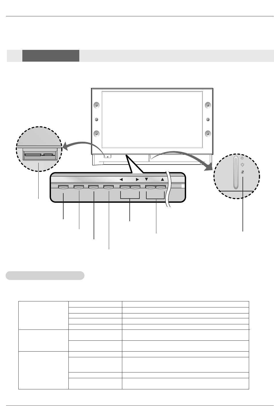
POWER TV GUIDE VOL CH
ENTER
MENU
POWER Button VOLUME (F,G)
Buttons
CHANNEL (E, D) Buttons Operation Indicator/
Lamp Indicator/
Temperature Indicator
ENTER Button
TV GUIDE Button
Off Power Cord is not connected.
Red Power Cord is connected, TV is in standby mode.
Green TV turns on.
Red (flashing) Power Cord is connected, TV is in booting sequence.
Orange (flashing) Preparing operation in standby mode.
Orange Projection lamp is reaching the end of its life and needs to
be replaced with a new lamp. Contact your service center.
Red (flashing) There is a problem with the lamp or around it. Contact an
authorized service center.
Green (flashing) The lamp cover is not closed.
Orange The projection TV is overheating. Check the blocked vents
of the Projection TV and the accumulated dust in the dust
filter.
Red The projection TV shuts down due to overheating.
Red (flashing) The projection TV shuts down, check the cooling fan.
Contact your service center.
Operation Indicator
Lamp Indicator
Temperature Indicator
- Lamp indicator, operation indicator, and temperature indicator located below the front panel controls, reveal the
operating status of the DLP projection TV.
Function Status Indicators
Function Status Indicators
Memory Card
Slots
MENU Button
Controls
Controls
Front Panel Controls
Front Panel Controls
DLP Projection TV
Introduction
PC/DTV
(XGA/
480p/
720p
1080i)
DVI
RGB/DVI
UPGRADE PORT
/
P
R
P
B
Y
DTV/DVD
RGB
PC/DTV
(XGA/
480p/
720p
1080i)
PC/DTV
(XGA
/480p
/720p
/1080i)
S-VIDEO
PR
PB
Y
MONO
CABLE
RGB INPUT
COMPONENT
INPUT2 INPUT1
DTV/DVD INPUT
RGB/DVI INPUT
(L)
(R)
AUDIO
(L)
(R)
AUDIO
VIDEO
(L)
(R)
AUDIO
(L)
(R)
AUDIO
AUDIO
CENTER
MODE IN
MONITOR
OUTPUT
VIDEO
INPUT2
VIDEO
INPUT1
DIGITAL AUDIO
OPTICAL INPUT1
(COMPONENT2)
DIGITAL AUDIO
OPTICAL INPUT2
(DVI)
IEEE1394
DIGITAL AUDIO
OPTICAL OUTPUT
ANTENNA
C
A
B
L
E
C
A
R
D
HDMI1/DVI
VARIABLE
AUDIO OUT
G-LINK
HDMI2
UPGRADE
PORT
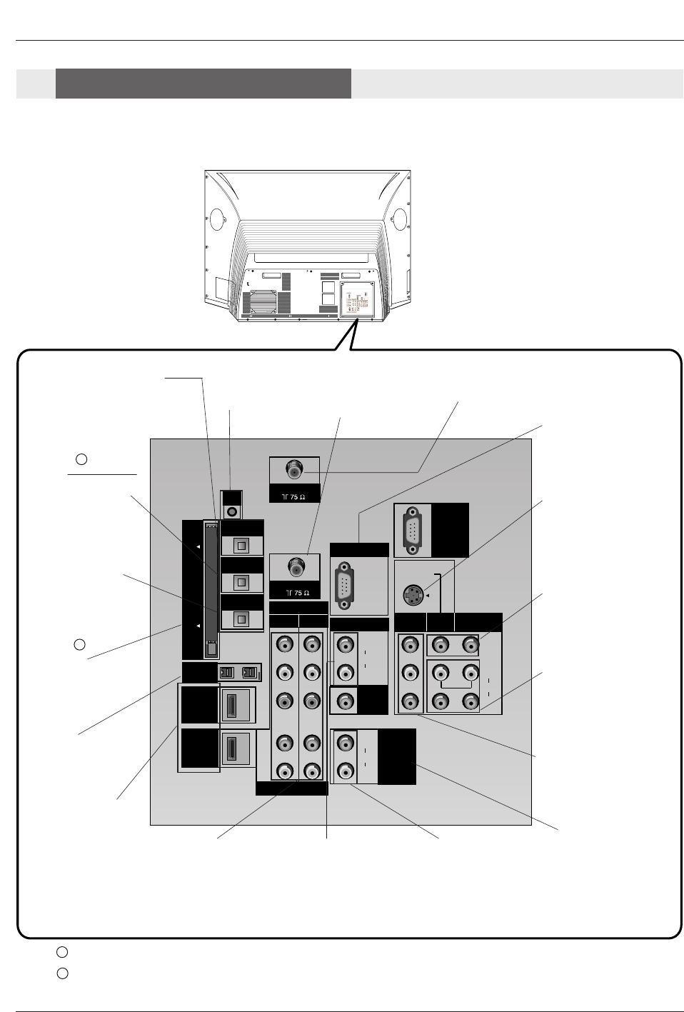
ANTENNA Inputs
Connect antenna sig-
nals to the TV directly.
DIGITAL AUDIO OPTICAL
OUTPUT
Used to connect either an exter-
nal amplifier, or add a sub-
woofer to your surround sound
system if it has a digital
audio optical input.
(Refer to )
MONITOR OUTPUT
Connect a second TV or
Monitor.
S-VIDEO In
A connection available
with some high-end
equipment that provides
even better picture qual-
ity for Video 2.
RGB/DVI INPUT
Connect the monitor
output connector from
a PC to the appropri-
ate input port.
RGB Input
Connect the TV output
connector from a PC/DTV
to the appropriate input
port.
AUDIO CENTER
MODE IN
Connect to external
Dolby Digital Center
“preamp output.”
VARIABLE AUDIO OUT
Used to connect either
an external amplifier,
or add a sub-woofer to
your surround sound
system.
COMPONENT INPUT 1-2
Connect a component
video/audio device to
these jacks. Refer to your
DVD manual for further
information.
VIDEO 1 or 2
Connects the video sig-
nals from various types
of equipment.
Left/Right AUDIO
Used for stereo sound
from various types of
equipment.
IEEE1394
Connect DVHS or
MicroMV to IEEE1394
Connector.
CableCARD™
Used for CableCARD™
received Cable Service
Provider.
CABLE Inputs
Connect cable signals to
the TV, either directly or
through your cable box.
G-LINK
Connect a G-
LINK Cable to
this jack.
DIGITAL AUDIO OPTI-
CAL INPUT1(COMPO-
NENT2)
Connect digital audio
from the equipment
whose video is connect-
ed to COMPONENT 2.
DIGITAL AUDIO OPTI-
CAL INPUT2(DVI)
Connect digital audio
from the equipment
whose video is connect-
ed to
HDMI/DVI(VIDEO).
(Refer to )
Notes: In standby mode, these port will not work.
If the video is connected through HDMI-TO-HDMI cable, you don’t need to connect digital audio. This port
is used only when the video connected through DVI-TO-HDMI cable.
1
2
1
2
HDMI1/DVI, HDMI 2
Connect a HDMI signal
to HDMI1/DVI or
HDMI2. Or connect a
DVI(Video) signal to
HDMI1/DVI.
Back Connection Panel
Back Connection Panel
Connection Options
Connection Options

Owner’s Manual
Introduction
LEFT/RIGHT
AUDIO
Used for stereo
sound from vari-
ous types of
equipment.
S-VIDEO
A connection
available on some
very high-end
equipment that
provides better
picture quality
than video input.
VIDEO
Connects the
video signals
from any piece of
equipment.
Front A/V Panel
S-VIDEO
VIDEO
FRONT A/V
AUDIO
(R)
(L)/
MONO
There are four jacks on the left side on your projection TV
that make connecting Audio/Video devices like video games
and camcorders very simple.
The jacks are like those found on the back jack connection
panel. This means that most equipment that connects to
those types of jacks on the rear jackpack, may be connect-
ed to the front connection panel.
To use the side jacks as the signal source, select them
using Main Input menu as described on page 58. They will
be named “Front Video” in the Main Input menu.
If you input both Front Video and
S-Video, only the S-Video will
work.
If you’re connecting a video game
device, make sure to change the
picture settings with the EZ
Picture option in the Video menu
(see page 59).
Mini glossary
A/V CABLESAudio/Video cables. Three cable connector—Right audio (red), Left audio (white), and Video (yellow). A/V cables are
used for stereo playback of videocassettes and for higher quality picture and sound from other A/V devices.
A/V DEVICE Any device that produces video or sound (VCR, DVD, cable box, or television).
Front Connection Panel
Front Connection Panel
DLP Projection TV
Installation
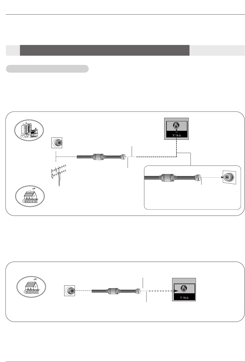
- Wall Antenna Socket or Outdoor Antenna without a Cable Box Connections
- For optimum picture quality, adjust antenna direction if needed.
Antenna or Cable Connection
Antenna or Cable Connection
1. Analog and Digital TV signals provided on antenna
2. Analog and Digital TV signals provided on cable
ANTENNA
Multi-family Dwellings/Apartments
(Connect to wall antenna socket)
Single-family Dwellings /Houses
(Connect to wall jack for outdoor antenna)
Outdoor
Antenna
Wall Antenna
Socket
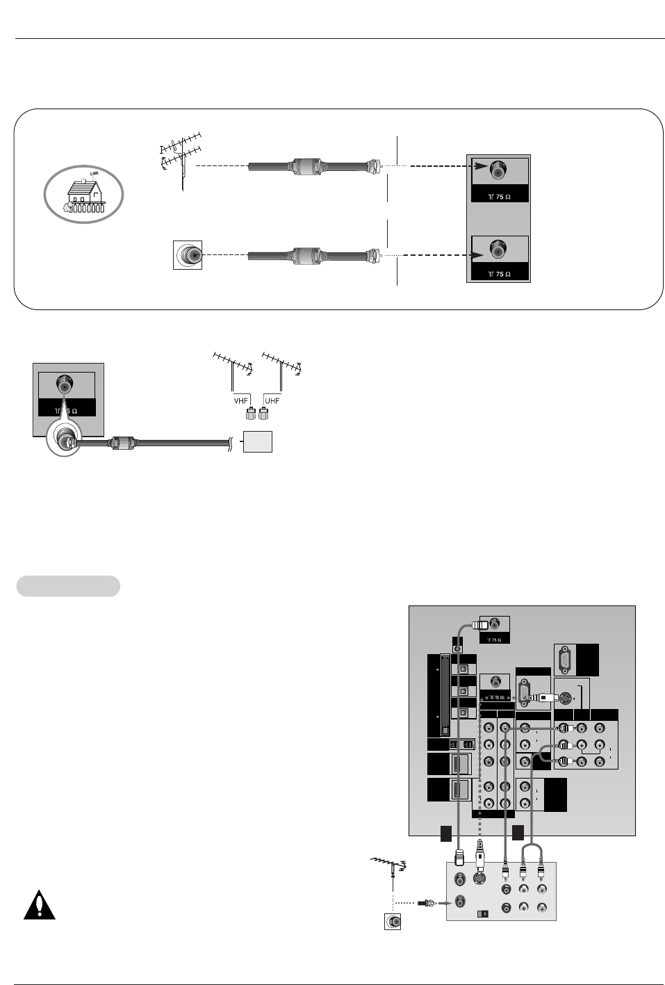
VHF Antenna
UHF Antenna
RF Coaxial Wire (75 ohm)
Bronze Wire
Turn clockwise to tighten.
Bronze Wire
Be careful not to bend the bronze wire when
connecting the antenna.
Bronze Wire
Cable TV Wall
Jack RF Coaxial Wire (75 ohm)
CABLE
Installation
Installation
External Equipment Connections
External Equipment Connections
Turn clockwise to tighten.
Owner’s Manual
Note: The TV will let you know when the TV(analog antenna), DTV(digital antenna), CATV(analog cable) and CADTV(digital
cable) channel scans are complete.
•In a poor signal area to improve picture quality, purchase
and install a signal amplifier.
•If the antenna or cable needs to be split for two TV’s,
install a “2-Way Signal Splitter” in the connections.
•If the antenna or cable is not installed properly, contact
your dealer for assistance.
ANTENNA
Signal
Amplifier
3. Analog and Digital TV signals provided on cable and antenna
Antenna
RF Coaxial Wire (75 ohm)
Bronze Wire
Turn clockwise to tighten.
Cable TV Wall
Jack RF Coaxial Wire (75 ohm)
CABLE
ANTENNA
Connection Option 1
Set VCR output switch to channel 3 or 4 and then tune the
TV to the same channel number.
Connection Option 2
1. Connect the audio and video cables from the VCR's output
jacks to the TV input jacks, as shown in the figure.
When connecting the TV to VCR, match the jack colors
(Video = yellow, Audio Left = white, and Audio Right = red).
If you connect an S-VIDEO output from VCR to the S-VIDEO
input, the picture quality is improved; compared to connecting
a regular VCR to the Video input.
2. Insert a video tape into the VCR and press PLAY on the
VCR. (Refer to the VCR owner’s manual.)
3. Select the input source with using the TV/VIDEO button on
the remote control. Note that this TV finds the connected
input sources automatically for Video, Front Video and
Component 1-2. It is presumed that RGB, HDMI1/DVI and
HDMI2 sources are connected.
Do not connect to both Video and S-Video at the
same time. In the event that you connect both Video
and the S-Video cables, only the S-Video will work.)
VCR Setup
VCR Setup
PC/DTV
(XGA
/480p
/720p
/1080i)
S-VIDEO
PR
PB
Y
MONO
CABLE
RGB INPUT
COMPONENT
INPUT2 INPUT1
DTV/DVD INPUT
RGB/DVI INPUT
(L)
(R)
AUDIO
(L)
(R)
AUDIO
VIDEO
(L)
(R)
AUDIO
(L)
(R)
AUDIO
AUDIO
CENTER
MODE IN
MONITOR
OUTPUT
VIDEO
INPUT2
VIDEO
INPUT1
DIGITAL AUDIO
OPTICAL INPUT1
(COMPONENT2)
DIGITAL AUDIO
OPTICAL INPUT2
(DVI)
IEEE1394
DIGITAL AUDIO
OPTICAL OUTPUT
ANTENNA
C
A
B
L
E
C
A
R
D
DVI
VARIABLE
AUDIO OUT
G-LINK
HDMI
UPGRADE
PORT
S-VIDEO OUT
IN
(R) AUDIO (L)VIDEO
34
OUTPUT
SWITCH
ANT OUT
ANT IN
VCR Rear
12
Installation
Bronze Wire
DLP Projection TV
Installation
•Component Input ports
To get better picture quality, connect a DVD player to the
component input ports as shown below.
Component ports
on the TV Y PBPR
Video output ports
on DVD player
Y
Y
Y
Y
Pb
B-Y
Cb
PB
Pr
R-Y
Cr
PR
How to connect
1. Connect the DVD video outputs (Y, PB, PR) to the COMPO-
NENT (Y, PB, PR) INPUT jacks on the TV and connect the
DVD audio outputs to the AUDIO INPUT jacks on the TV, as
shown in the figure.
2. If your DVD only has an S-Video output jack, connect this to
the S-VIDEO input on the TV and connect the DVD audio out-
puts to the AUDIO INPUT jacks on the TV, as shown in the fig-
ure.
Note: If your DVD player does not have component video output,
use S-Video.
How to use
1. Turn on the DVD player, insert a DVD.
2. Use the TV/VIDEO button on the remote control to select
Component 1 or Component 2. (If connected to S-VIDEO,
select the Video or Front Video external input source.)
3. Refer to the DVD player's manual for operating instructions.
DVD Setup
DVD Setup
PC/DTV
(XGA
/480p
/720p
/1080i)
S-VIDEO
PR
PB
Y
MONO
CABLE
RGB INPUT
COMPONENT
INPUT2 INPUT1
DTV/DVD INPUT
RGB/DVI INPUT
(L)
(R)
AUDIO
(L)
(R)
AUDIO
VIDEO
(L)
(R)
AUDIO
(L)
(R)
AUDIO
AUDIO
CENTER
MODE IN
MONITOR
OUTPUT
VIDEO
INPUT2
VIDEO
INPUT1
DIGITAL AUDIO
OPTICAL INPUT1
(COMPONENT2)
DIGITAL AUDIO
OPTICAL INPUT2
(DVI)
IEEE1394
DIGITAL AUDIO
OPTICAL OUTPUT
ANTENNA
C
A
B
L
E
C
A
R
D
DVI
VARIABLE
AUDIO OUT
G-LINK
HDMI
UPGRADE
PORT
(R) AUDIO (L)
S-VIDEO
BR
(R) AUDIO (L) DIGITAL AUDIO
OPTICAL
DVD
Notes:
• Digital Audio will not work for Component 1 input source.
• Digital Audio operation has priority if Digital Audio and AUDIO L/R
are connected at the same time.
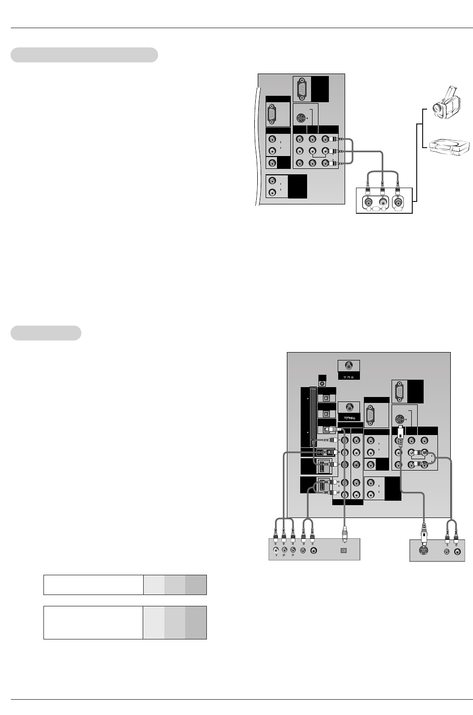
or
How to connect
Connect the audio and video cables from the external equip-
ment's output jacks to the TV input jacks, as shown in the
figure.
When connecting the TV to external equipment, match the
jack colors (Video = yellow, Audio Left = white, and Audio
Right = red).
How to use
1. Select the input source with using the TV/VIDEO button on
the remote control. Note that this TV finds the connected
input sources automatically for Video 1-2 and Component 1-
2. It is presumed that RGB, HDMI1/DVI and HDMI2 sources
are connected.
2. Operate the corresponding external equipment. For connec-
tion instructions for operating the TV Guide On Screen sys-
tem, see page 21.
External
External A/V Source Setup
A/V Source Setup
PC/DTV
(XGA
/480p
/720p
/1080i)
S-VIDEO
MONO
RGB INPUT
RGB/DVI INPUT
(L)
(R)
AUDIO
(L)
(R)
AUDIO
VIDEO
(L)
(R)
AUDIO
AUDIO
CENTER
MODE IN
MONITOR
OUTPUT
VIDEO
INPUT2
VIDEO
INPUT1
RL
AUDIO VIDEO
VARIABLE
AUDIO OUT
UPGRADE
PORT
Camcorder
Video Game
Set
Owner’s Manual
Installation
The TV has a special signal output capability which allows you to
hook up a second TV or monitor.
Connect the second TV or monitor to the TV’s MONITOR OUTPUT.
See the Operating Manual of the second TV or monitor for further
details regarding that device’s input settings.
Note
• Component, RGB-PC/RGB-DTV, HDMI1/DVI,HDMI2, DTV input
sources cannot be used for Monitor out.
Monitor Out Setup
Monitor Out Setup
S-VIDEO IN
(R) AUDIO (L) VIDEO
PC/DTV
(XGA
/480p
/720p
/1080i)
S-VIDEO
MONO
RGB INPUT
RGB/DVI INPUT
(L)
(R)
AUDIO
(L)
(R)
AUDIO
VIDEO
(L)
(R)
AUDIO
AUDIO
CENTER
MODE IN
MONITOR
OUTPUT
VIDEO
INPUT2
VIDEO
INPUT1
VARIABLE
AUDIO OUT
UPGRADE
How to connect
Use the TV’s COMPONENT (Y, PB, PR) INPUT, RGB, HDMI1/DVI or HDMI2
jack for video connections, depending on your set-top box connector. Then,
make the corresponding audio connections.
Note: HDMI(High Definition Multimedia Interface): Input that accepts uncom-
pressed digital signal and multi channel digital audio signal.
How to use
1. Turn on the digital set-top box. (Refer to the owner’s manual for the digital
set-top box.)
2. Use TV/VIDEO on the remote control to select Component 1, Component
2, RGB-DTV, or HDMI/DVI source.
HDSTB Setup
HDSTB Setup
- This TV can receive Digital Over-the-air/Cable signals without an external digital set-top box. However, if you do receive Digital
signals from a digital set-top box or other digital external device, refer to the figure as shown below.
- This TV supports HDCP (High-bandwidth Digital Contents Protection) protocol for Digital Contents (480p,720p,1080i).
Signal
480i
480p
720p
1080i
Component 1/2
Yes
Yes
Yes
Yes
RGB-DTV,HDMI/DVI
No
Yes
Yes
Yes
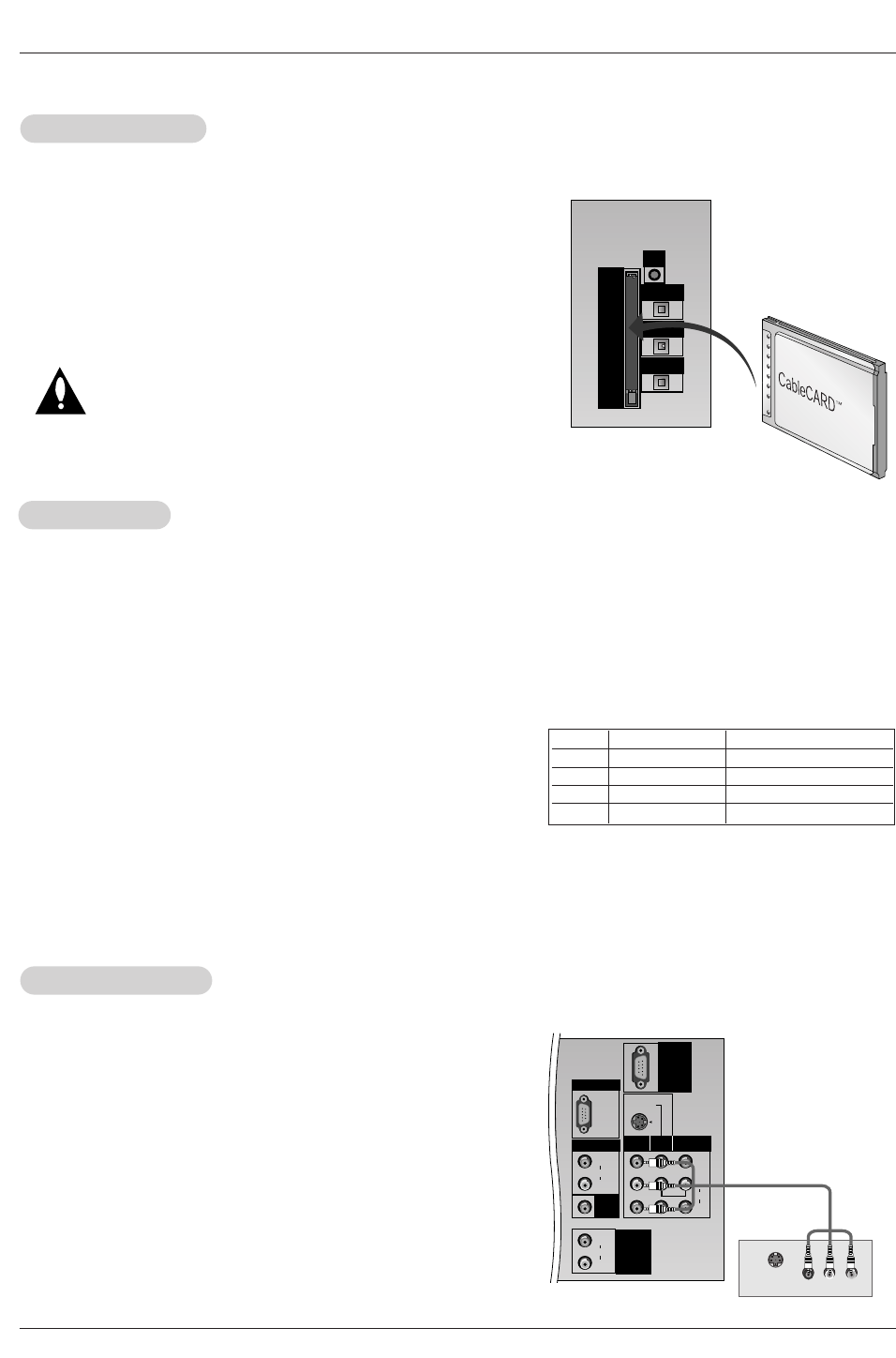
CableCARD
CableCARDTM
TM Setup
Setup
DIGITAL AUDIO
OPTICAL INPUT1
(COMPONENT2)
DIGITAL AUDIO
OPTICAL INPUT2
(DVI)
DIGITAL AUDIO
OPTICAL OUTPUT
Cable
CARD
G-LINK
How to use
Insert the CableCARDTM
TM received from the cable service provider to the
CableCARDTM
TM slot of TV back panel.
If the pairing information about this TV and the CableCARD is automatically
displayed on the screen, contact with the cable service provider by phone.
Note :
• CableCARDTM
TM have the types of Motorola, Scientific Atlanta, SCM etc..
These 3 types of CableCARDTM
TM can be used for this PLASMA TV.
Caution: When removing the CableCARDTM
TM, do not
drop it as this may cause impact to the
CableCARDTM
TM.
DLP Projection TV
Installation
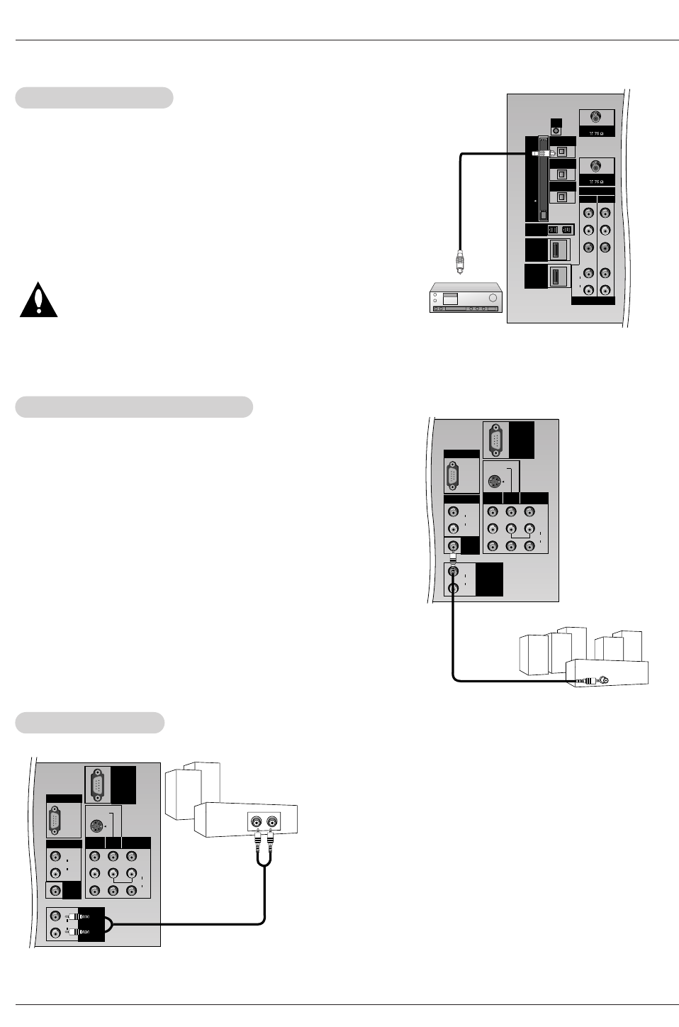
Send the TV’s audio to external audio equipment (stereo system) via
the Digital Audio Output (Optical) port.
How to connect
1. Connect one end of an optical cable to the TV Digital Audio
(Optical) Output port.
2. Connect the other end of the optical cable to the digital audio (opti-
cal) input on the audio equipment.
3. Set the “ TV Speaker option - Off”in the AUDIO menu. Refer to
page 65.
See the external audio equipment instruction manual for operation.
Caution: Do not look into the optical output port. Looking
at the laser beam may damage your vision.
Digital
Digital Audio Output
Audio Output
PR
PB
Y
CABLE
COMPONENT
INPUT2 INPUT1
DTV/DVD INPUT
(L)
(R)
AUDIO
ANTENNA
DIGITAL AUDIO
OPTICAL INPUT1
(COMPONENT2)
DIGITAL AUDIO
OPTICAL INPUT2
(DVI)
IEEE1394
DIGITAL AUDIO
OPTICAL OUTPUT
C
A
B
L
E
C
A
R
D
DVI
G-LINK
HDMI
How to connect
1. Connect the Dolby Digital Output jacks from the TV to the input jacks
on the Dolby Digital Receiver.
2. Set up your Dolby Digital Receiver according to the directions provid-
ed with that device.
3. If you wish to use your TV as the “Center channel” for your home
theater, re-direct the center channel to Center speaker mode input
jack on the TV.
Set the TV Speaker option to - “Center ” on the AUDIO menu. Refer to
page 60.
Dolby Digital
Dolby Digital Audio Connection
Audio Connection
Dolby Digital A/V Receiver
Center Channel
Preamp
Out
Front Left
Front Right
Rear Left
Surround
Rear Right
Surround
Powered
Subwoofer
PC/DTV
(XGA
/480p
/720p
/1080i)
S-VIDEO
MONO
RGB INPUT
RGB/DVI INPUT
(L)
(R)
AUDIO
(L)
(R)
AUDIO
VIDEO
(L)
(R)
AUDIO
AUDIO
CENTER
MODE IN
MONITOR
OUTPUT
VIDEO
INPUT2
VIDEO
INPUT1
VARIABLE
AUDIO OUT
UPGRADE
Hook up Variable Audio Output, L-Audio-R to Amplifier system for
Left/Right front speaker sound.
How to connect
1. Locate the Variable Audio Out jacks on the back of your TV and the
Input jacks on the back of your stereo's amplifier.
2. Connect the two jacks, making sure that the right and left channels
are connected correctly.
3. Set up your speakers through your analog stereo amplifier, accord-
ing to the instructions provided with the amplifier.
External Stereo
External Stereo
PC/DTV
(XGA
/480p
/720p
/1080i)
S-VIDEO
MONO
RGB INPUT
RGB/DVI INPUT
(L)
(R)
AUDIO
(L)
(R)
AUDIO
VIDEO
(L)
(R)
AUDIO
AUDIO
CENTER
MODE IN
MONITOR
OUTPUT
VIDEO
INPUT2
VIDEO
INPUT1
VARIABLE
AUDIO OUT
UPGRADE
Owner’s Manual
Installation
<When the PC supports DVI>
How to connect
1. Connect the PC to HDMI1/DVI port of this TV with an HDMI-to-DVI cable(not supplied with this product).
If you do not need to connect audio, HDMI2 port is also available for the DVI video connection.
2. If the PC(or the sound card of the PC) has a fiber optic digital audio output connector, connect the PC's audio output to DIGI-
TAL AUDIO(OPTICAL) port for DVI INPUT.
3. If the PC(or the sound card of the PC) has an analog audio output connector, connect the PC's audio output to AUDIO INPUT
port located on the right side of RGB INPUT port.
How To Use
1. To get the best picture quality, adjust the PC graphics card to 1024x768, 60Hz.
2. Select HDMI1/DVI input source in main input option of SETUP menu.(Refer to P.58)
TV/VIDEO button is also available for this purpose.
3. Check the image on your TV. There may be noise associated with the resolution, vertical pattern, contrast or brightness in PC
mode. If noise is present, change the PC output to another resolution, change the refresh rate to another rate or adjust the
brightness and contrast on the VIDEO menu until the picture is clear. If the refresh rate of the PC graphic card can not be
changed, change the PC graphic card or consult the manufacturer of the PC graphic card.
<When the PC supports RGB>
How to connect
1. Connect the PC to RGB INPUT port of this TV with a RGB cable(not supplied with this product).
2. If the PC(or the sound card of the PC) has an analog audio output connector, connect the PC's audio output to AUDIO INPUT
port located on the right side of RGB INPUT port.
How To Use
1. To get the best picture quality, adjust the PC graphics card to 1024x768, 60 Hz.
2. Select RGB-PC input source in main input option of SETUP menu.(Refer to P.58)
Once you select RGB-PC in main input option of SETUP menu, TV/VIDEO button is also available for this purpose.
3. Check the image on your TV. There may be noise associated with the resolution, vertical pattern, contrast or brightness in PC
mode. If noise is present, change the PC output to another resolution, change the refresh rate to another rate or adjust the
brightness and contrast on the VIDEO menu until the picture is clear. If the refresh rate of the PC graphic card can not be
changed, change the PC graphic card or consult the manufacturer of the PC graphic card.
PC Setup
PC Setup
- This TV provides Plug and Play capability, meaning that the PC adjusts automatically to the TV's settings.
- The TV perceives 640x480, 60Hz as DTV 480p based on the PC graphic card, change the screen scanning rate for the graphic
card accordingly.
720x400
800x600
70.08
85.03
59.94
72.80
75.00
85.00
35.156
37.879
48.077
46.875
53.674
48.363
56.476
60.023
56.25
60.31
72.18
75.00
85.06
60.00
70.06
75.02
Vertical
Frequency(Hz) Resolution Horizontal
Frequency(KHz)
Vertical
Frequency(Hz)
1024x768
Resolution
640x480
Horizontal
Frequency(KHz)
31.469
37.927
31.469
37.861
37.500
43.269
Monitor Display Specifications (RGB-PC )
Resolution
640x480
800x600
Horizontal
Frequency(KHz)
31.469
37.861
37.500
35.156
37.879
48.077
46.875
59.94
72.80
75.00
56.25
60.31
72.18
75.00
48.363
56.476
60.023
60.00
70.06
75.02
Vertical
Frequency(Hz) Resolution Horizontal
Frequency(KHz)
Vertical
Frequency(Hz)
1024x768
Monitor Display Specifications (HDMI/DVI Mode)

DLP Projection TV
Installation
- HDMITM, the HDMI logo and High-Definition Multimedia Interface are trademarks or registered trademarks of HDMI Licensing LLC."
- This TV can receive the High-Definition Multimedia Interface(HDMI) or the Digital Visual Interface(DVI).
- This TV supports HDCP(High-bandwidth Digital Contents Protection) Protocol for 720x480p, 1280x720p, and 1920x1080i resolu-
tion.
- When you connect this TV with a source device(DVD player, Set Top Box or PC) supporting Auto HDMI/DVI function, the output
resolution of the source device will be automatically set to 1280x720p.
- If the source device does not support Auto HDMI/DVI, you need to set the output resolution appropriately.
To get the best picture quality, adjust the DVD Player or Set Top Box's output resolution to 1280x720p, and the PC graphics card's
output resolution to 1024x768, 60Hz.
- If the source device has an HDMI output, no other audio connection is necessary because HDMI-to-HDMI connection includes
both video and audio.
- If the source device has a DVI output and no HDMI output, a separated audio connection is necessary.
<When the source device(DVD player or Set Top Box) supports HDMI>
How To Connect
1. Connect the source device to HDMI1/DVI or HDMI2 port of this TV with an HDMI cable(not supplied with this product).
2. No separated audio connection is necessary.
How To Use
- If the source device supports Auto HDMI function, the output resolution of the source device will be automatically set to 1280x720p.
- If the source device does not support Auto HDMI, you need to set the output resolution appropriately.
To get the best picture quality, adjust the output resolution of the source device to 1280x720p.
- Select HDMI1/DVI or HDMI2 input source in main input option of SETUP menu.(Refer to P.58)
TV/VIDEO button is also available for this purpose.
<When the source device(DVD player or Set Top Box) supports DVI>
How To Connect
1. Connect the source device to HDMI1/DVI port of this TV with a HDMI-to-DVI cable(not supplied with this product).
Do not use HDMI2 port for DVI connection if you want to connect audio.
2. A separated audio connection is necessary.
3. If the source device has a fiber optic digital audio output, connect the audio output to DIGITAL AUDIO(OPTICAL) port for DVI
INPUT.
4. If the source device has an analog audio output connector, connect the PC's audio output to AUDIO INPUT port located on the
right side of RGB INPUT port.
How To Use
- If the source device supports Auto DVI function, the output resolution of the source device will be automatically set to 1280x720p.
- If the source device does not support Auto DVI, you need to set the output resolution appropriately.
To get the best picture quality, adjust the output resolution of the source device to 1280x720p.
- Select HDMI1/DVI input source in main input option of SETUP menu.(Refer to P.58)
TV/VIDEO button is also available for this purpose.
HDMI
HDMI
Owner’s Manual
Installation
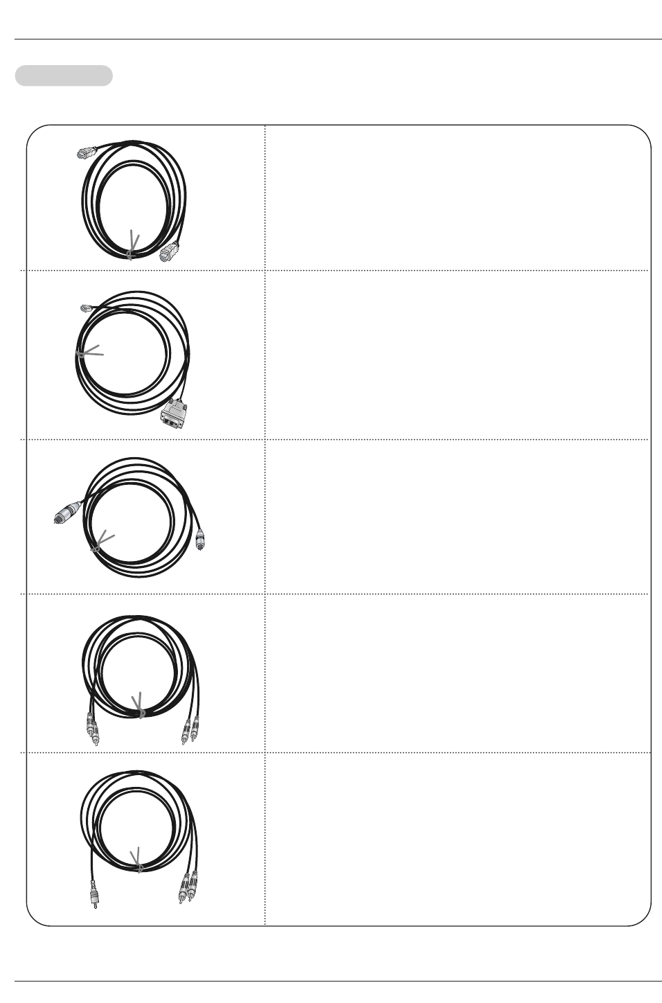
Cable sample
HDMI Cable
(not supplied with the product)
HDMI to DVI Cable
(not supplied with the product)
Fiber Optic Digital Audio Cable
(not supplied with the product)
Analog Audio Cable(RCA type)
(not supplied with the product)
Analog Audio Cable(Stereo to RCA type)
(not supplied with the product)
Reference
Reference
DLP Projection TV
HDMI
How to use
1. Connect the HDMI1/DVI Source Devices(DVD Player or Set Top Box or PC) and the TV SET.
2. Turn on the display by pressing the POWER button on the TV SET and HDMI1/DVI Source Devices remote control.
3. Select HDM1/DVI Input source in Main Input option of SETUP menu.(Refer to P.58)
4. Check the image on your TV SET. There may be noise associated with the resolution, vertical pattern, contrast or brightness in
HDMI1/DVI Source Devices. If noise is present, change the HDMI1/DVI Source Devices to another resolution, change the
refresh rate or adjust the brightness and contrast on the menu until the picture is clear. If the refresh rate of the PC graphics
card can not changed, change the PC graphics card or consult the manufacturer of the PC graphics card.
Notes:
- Depending on the graphics card, DOS mode may not work if you use a HDMI1 to DVI Cable.
- Avoid keeping a fixed image on the TV SET screen for a long period of time. The fixed image may become permanently imprint-
ed on the screen. Use the Orbiter screen saver when possible.
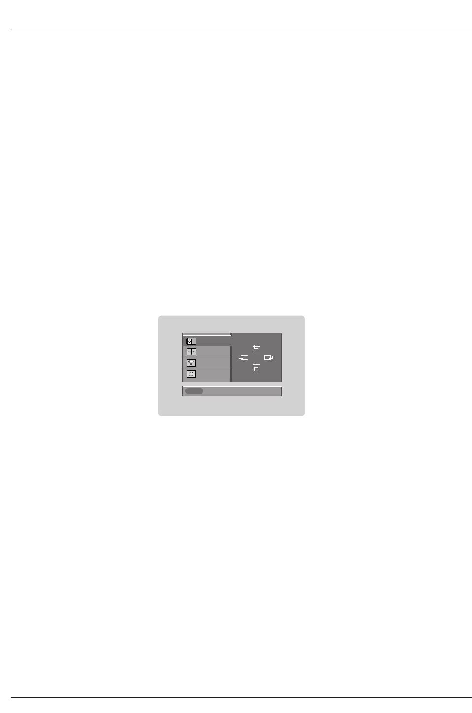
- When Source Devices connected HDMI/DVI Input, output PC Resolution(VGA, SVGA, XGA), Position, Size may not fit to
Screen. As shown the lower picture, press the ADJUST button to adjust the screen Position of TV SET and contact an PC
graphics card service center.
- When Source Devices connected HDMI1/DVI Input output TV SET Resolution(480p, 720p, 1080i), TV SET Display fit EIA/CEA-
861-B Specification to Screen. If not, refer to the Manual of HDMI1/DVI Source Devices or contact your service center.
- In case HDMI1/DVI Source Devices is not connected Cable or poor cable connection, "NO SIGNAL" OSD display in HDMI1/DVI
Input. And In case of, Video Resolution not supported TV SET output in HDMI1/DVI Source Devices, "INVALID FORMAT" OSD
display. Refer to the Manual of HDMI1/DVI Source Devices or contact your service center.
In This Mode, the Supported TV Set Resolution Specification
- 1920 x 1080 I @ 59.94Hz / 60Hz, 16:9
- 1280 x 720 P @ 59.94Hz / 60Hz, 16:9(preferred format)
- 720 x 480 P @ 59.94Hz / 60Hz, 16:9
- 720 x 480 P @ 59.94Hz / 60Hz, 4:3
In This Mode, the Supported PC Resolution Specification
- 640 x 350 @ 70Hz
- 640 x 480 @ 60Hz
- 640 x 480 @ 72Hz
- 640 x 480 @ 75Hz
- 800 x 600 @ 56Hz
- 800 x 600 @ 60Hz
- 800 x 600 @ 72Hz
- 800 x 600 @ 75Hz
- 1024 x 768 @ 60Hz(preferred format)
- 1024 x 768 @ 70Hz
- 1024 x 768 @ 75Hz
Close
POSITION G
SIZE
PHASE
RESET
Adjust
D
FG
E
Owner’s Manual
Installation
PC/DTV
(XGA
/480p
/720p
/1080i)
S-VIDEO
P
R
P
B
Y
MONO
CABLE
RGB INPUT
COMPONENT
INPUT2 INPUT1
DTV/DVD INPUT
RGB/DVI INPUT
(L)
(R)
AUDIO
(L)
(R)
AUDIO
VIDEO
(L)
(R)
AUDIO
(L)
(R)
AUDIO
AUDIO
CENTER
MODE IN
MONITOR
OUTPUT
VIDEO
INPUT2
VIDEO
INPUT1
DIGITAL AUDIO
OPTICAL INPUT1
(COMPONENT2)
DIGITAL AUDIO
OPTICAL INPUT2
(DVI)
IEEE1394
DIGITAL AUDIO
OPTICAL OUTPUT
ANTENNA
C
A
B
L
E
C
A
R
D
DVI
VARIABLE
AUDIO OUT
G-LINK
HDMI
UPGRADE
PORT
S-VIDEO
OUT
IN
(R) AUDIO (L) VIDEO
34
OUTPUT
SWITCH
ANT IN
ANT OUT
VCR Rear
VCR Front
VCR Rear
VCR Front
TV Guide On Screen Setup
TV Guide On Screen Setup
- The TV Guide On Screen system uses Setup information to provide you with show listings and lineups in your area—which are
updated several times a day.
- Once you set up the TV according to manufacturer’s instructions, you are ready to set up the TV Guide On Screen system.
Note:The TV Guide On Screen system interactive program guide provides listings for cable-ready, cable box, and digital cable
services as well as over-the-air broadcast. It does not provide listings for satellite services.
How to connect VCR and Cable Box
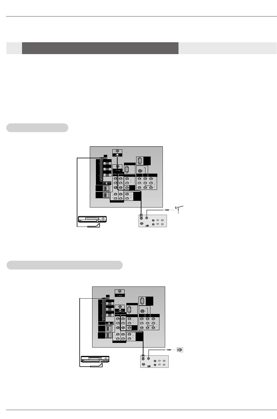
1.Antenna Service
1.Antenna Service
2. Cable Service without a Cable Box
2. Cable Service without a Cable Box
DLP Projection TV
Installation
PC/DTV
(XGA
/480p
/720p
/1080i)
S-VIDEO
P
R
P
B
Y
MONO
CABLE
RGB INPUT
COMPONENT
INPUT2 INPUT1
DTV/DVD INPUT
RGB/DVI INPUT
(L)
(R)
AUDIO
(L)
(R)
AUDIO
VIDEO
(L)
(R)
AUDIO
(L)
(R)
AUDIO
AUDIO
CENTER
MODE IN
MONITOR
OUTPUT
VIDEO
INPUT2
VIDEO
INPUT1
DIGITAL AUDIO
OPTICAL INPUT1
(COMPONENT2)
DIGITAL AUDIO
OPTICAL INPUT2
(DVI)
IEEE1394
DIGITAL AUDIO
OPTICAL OUTPUT
ANTENNA
C
A
B
L
E
C
A
R
D
DVI
VARIABLE
AUDIO OUT
G-LINK
HDMI
UPGRADE
PORT
S-VIDEO
OUT
IN
(R) AUDIO (L) VIDEO
RF
TV
VCR
Cable
(R) AUDIO (L) VIDEO
34
OUTPUT
SWITCH
34
OUTPUT
SWITCH
ANT IN
ANT OUT
PC/DTV
(XGA
/480p
/720p
/1080i)
S-VIDEO
P
R
P
B
Y
MONO
CABLE
RGB INPUT
COMPONENT
INPUT2 INPUT1
DTV/DVD INPUT
RGB/DVI INPUT
(L)
(R)
AUDIO
(L)
(R)
AUDIO
VIDEO
(L)
(R)
AUDIO
(L)
(R)
AUDIO
AUDIO
CENTER
MODE IN
MONITOR
OUTPUT
VIDEO
INPUT2
VIDEO
INPUT1
DIGITAL AUDIO
OPTICAL INPUT1
(COMPONENT2)
DIGITAL AUDIO
OPTICAL INPUT2
(DVI)
IEEE1394
DIGITAL AUDIO
OPTICAL OUTPUT
ANTENNA
C
A
B
L
E
C
A
R
D
DVI
VARIABLE
AUDIO OUT
G-LINK
HDMI
UPGRADE
PORT
S-VIDEO
OUT
IN
(R) AUDIO (L) VIDEO
RF
TV
VCR
Cable
(R) AUDIO (L) VIDEO
34
OUTPUT
SWITCH
34
OUTPUT
SWITCH
ANT IN
ANT OUT
Cable Box Rear
or
VCR Rear
VCR Front
Cable Box Front
VCR RearVCR Front
Cable Box Rear
VCR Rear
VCR Front
Cable Box Front
or
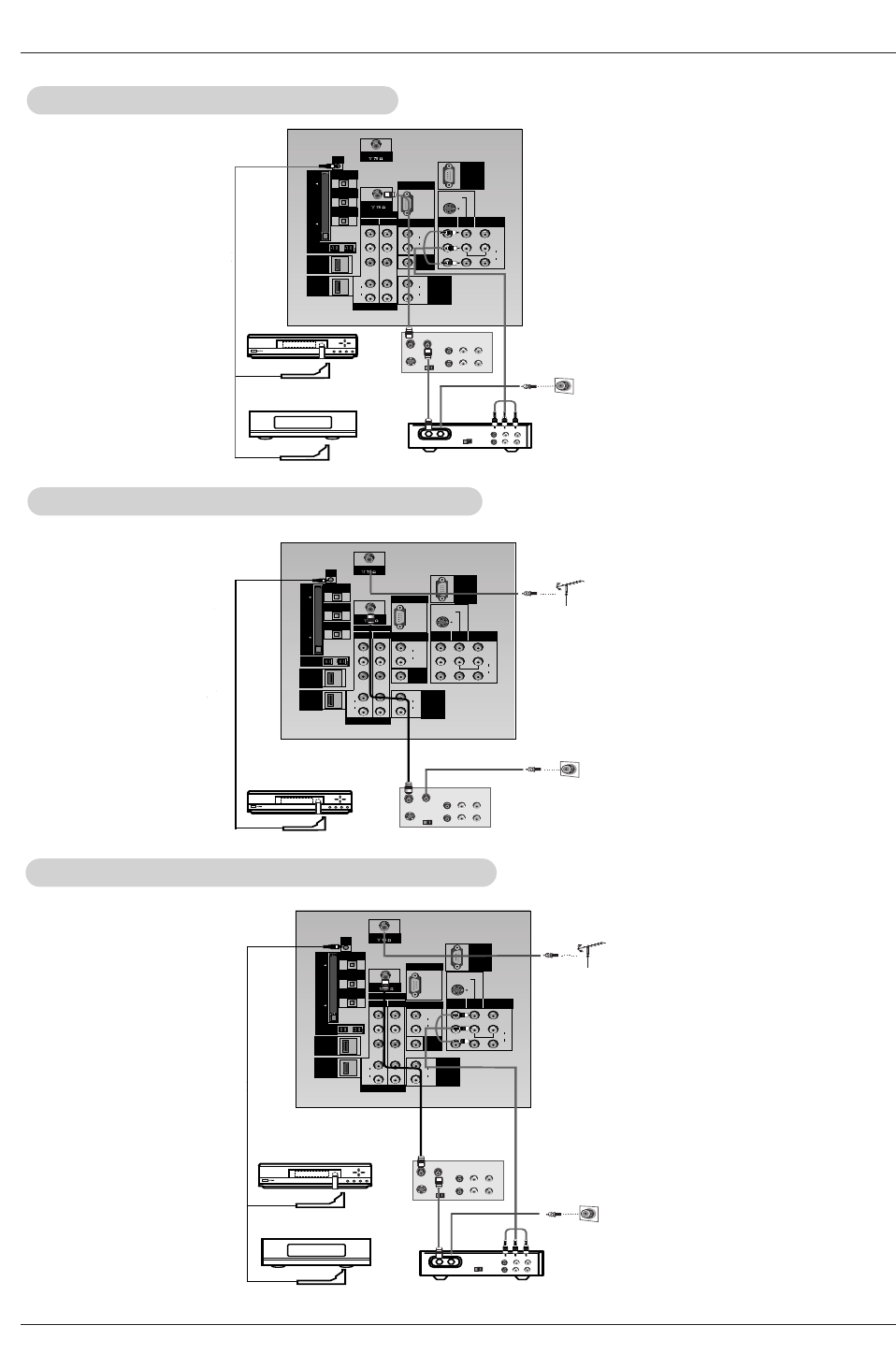
3.Cable Service without a Cable Box
3.Cable Service without a Cable Box
4. Antenna and Cable Service without a Cable Box
5.
5. Antenna and Cable Service with a Cable Box
Antenna and Cable Service with a Cable Box
Owner’s Manual
Installation
Note: The G-LINK cable is necessary for the TV Guide On Screen system to work with your Cable Box and VCR. See Page
20~21 for G-LINK connection instructions.
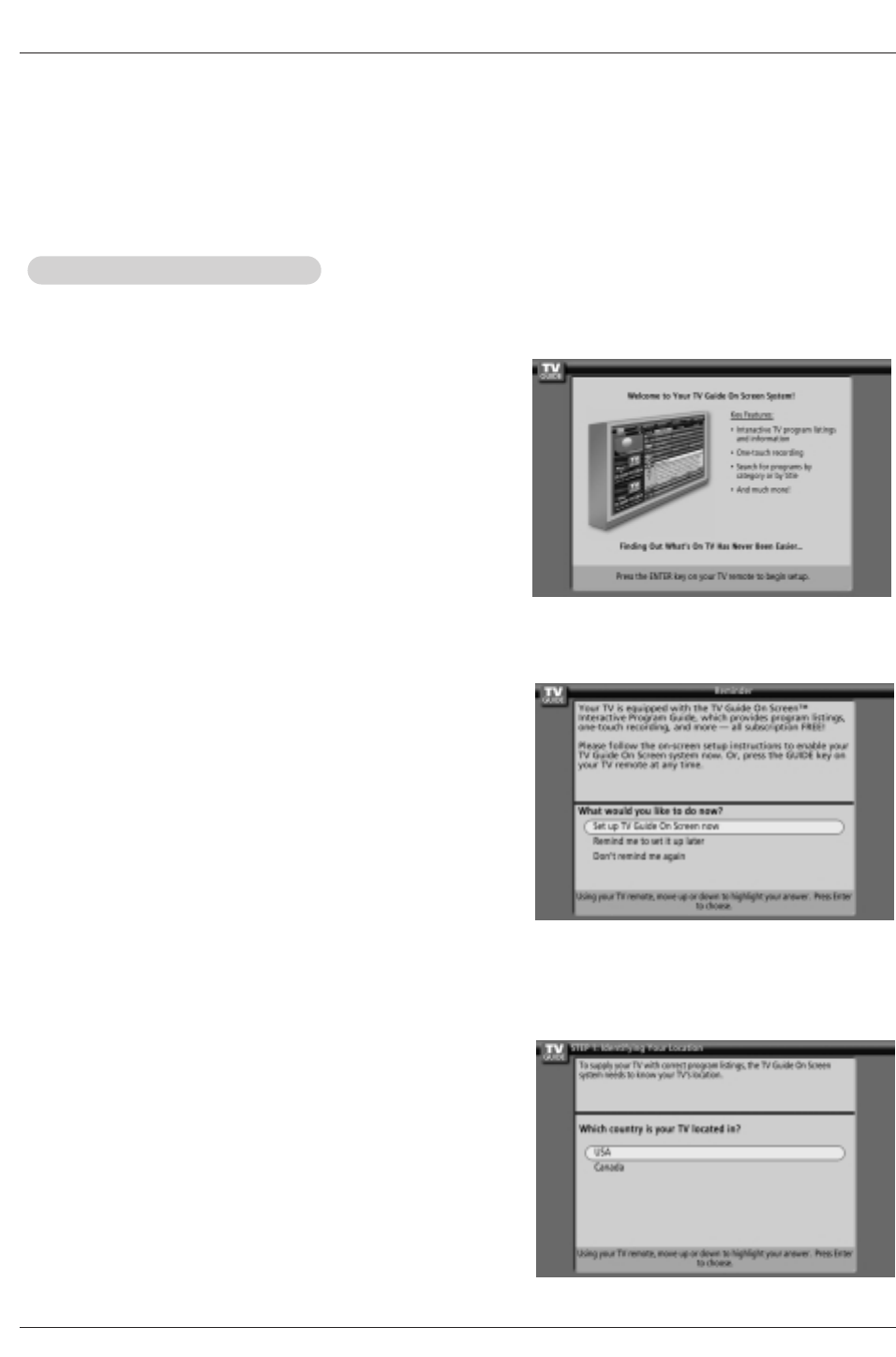
The TV Guide On Screen system's Reminder Screen appears:
-- after initial TV set up
-- if you power Off the TV and then power it back On
To make a selection, use the D/ Ebutton to highlight to an option,
and press ENTER.
• "Set up TV Guide On Screen now," displays the Welcome Screen.
Press ENTER to begin Setup.
• "Remind me to set up later" returns you to watching TV.
• "Don't remind me again" returns you to watching TV and stops the
reminder screen from appearing upon power On.
How to use
1. Screen 1: Country
• This screen asks you the location of your TV.
• Use the D/ Ebutton to highlight a country.
• Press ENTER to display Screen 2.
The TV Guide On Screen system's Welcome Screen appears:
-- by pressing the TV Guide key
-- when you power On your TV if you previously skipped "Set up TV
Guide On Screen now" on the Reminder Screen.
The Welcome Screen highlights features of the TV Guide On Screen
system.
Press ENTER to begin Setup.
2.Reminder Screen
1.Welcome Screen
TV Guide On Screen Setup
TV Guide On Screen Setup
DLP Projection TV
Installation
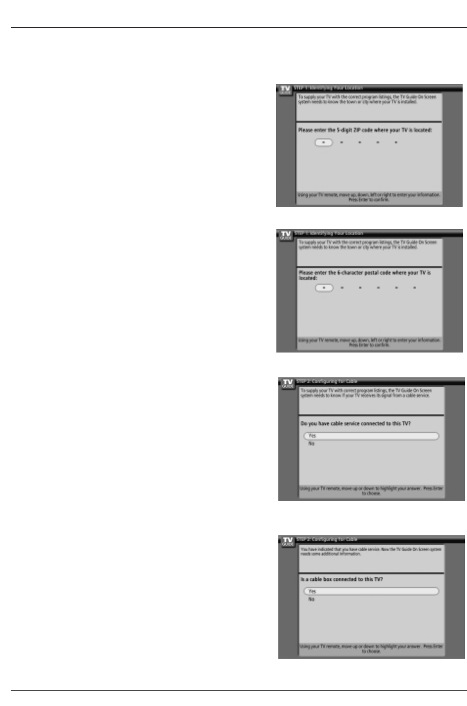
4. Screen 2: Enter Zip or Postal Code
Option 1
•If you selected USA in Screen 1, you see the ZIP Code screen.
•You input numbers by either pressing the number keys on the remote
or using the D/ Ebuttons to display a number, and then the F / G but-
tons to move to another field.
•Press ENTER to display Screen 3.
Option 2
•If you selected Canada in Screen 1, you see the Postal Code screen.
•You input characters by using the D/ Ebuttons, and then the F / G
buttons to move to another field.
•Press ENTER to display Screen 3.
5. Screen 3: Do you have Cable?
•If you select Yes, you see Screen 4.
•If you select No, you see Screen 12.
6. Screen 4: Do you have a Cable Box?
•If you select Yes, you see Screen 5.
•If you select No, you see Screen 12.

Owner’s Manual
Installation
8. Screen 6: Cable Box Tuning Channel
•Select the channel used for the cable box.
•Press ENTER to display Screen 7.
9. Screen 7: Cable Box Configuration Diagram
•The diagram shows the correct way to install the G-LINK Cable from
the back of the device to the cable box.
Make sure the G-LINK Cable is properly installed.
•Press ENTER to display Screen 8.
7. Screen 5: Which TV input is the cable box plugged into?
•If you select Cable, you see Screen 6.
•If you make any other choice, you see Screen 7 .
DLP Projection TV
Installation
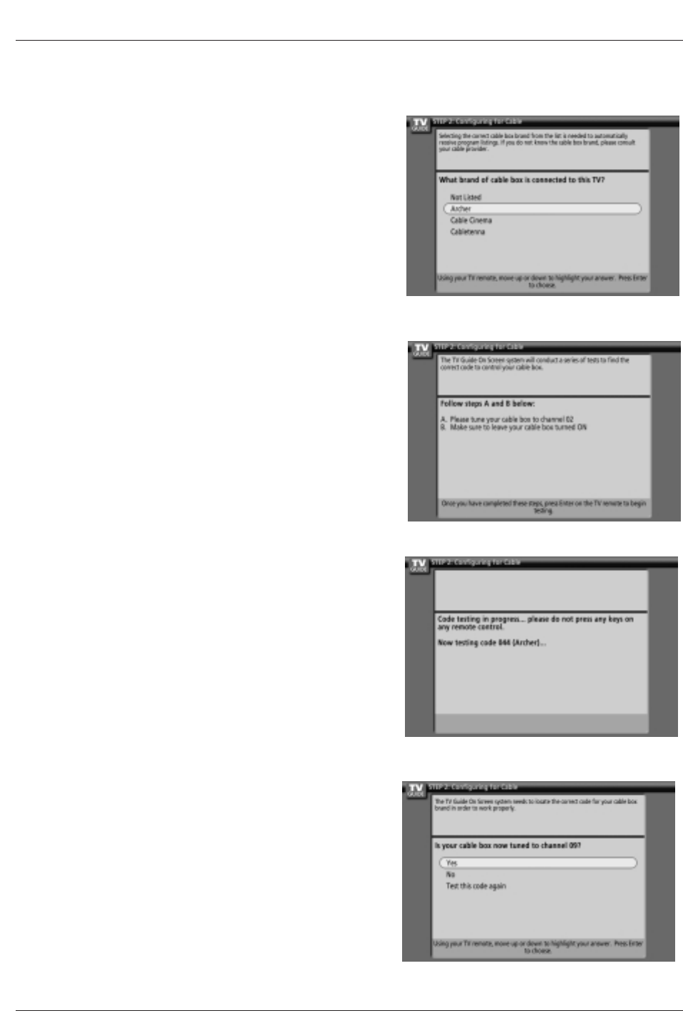
10. Screen 8: Cable Box Brand Name
•Use the D/ Ebuttons to select a cable box brand.
•Press ENTER to display Screen 9.
11. Screen 9: Cable Box Preparation
Follow the on-screen instructions, and press ENTER to display
Screen 10.
12. Screen 10: Cable Box Code Testing
When testing is done, Screen 11 displays automatically.
13. Screen 11: Cable Box Tuned to Channel 9?
If you select Yes, you see Screen 12.
If you select No, a different code is tested in Screen 10.
Notes: Many Cable Boxes require testing more than one code.
If you select Test this code again, the same code is tested again
in Screen 10.
Owner’s Manual
Installation
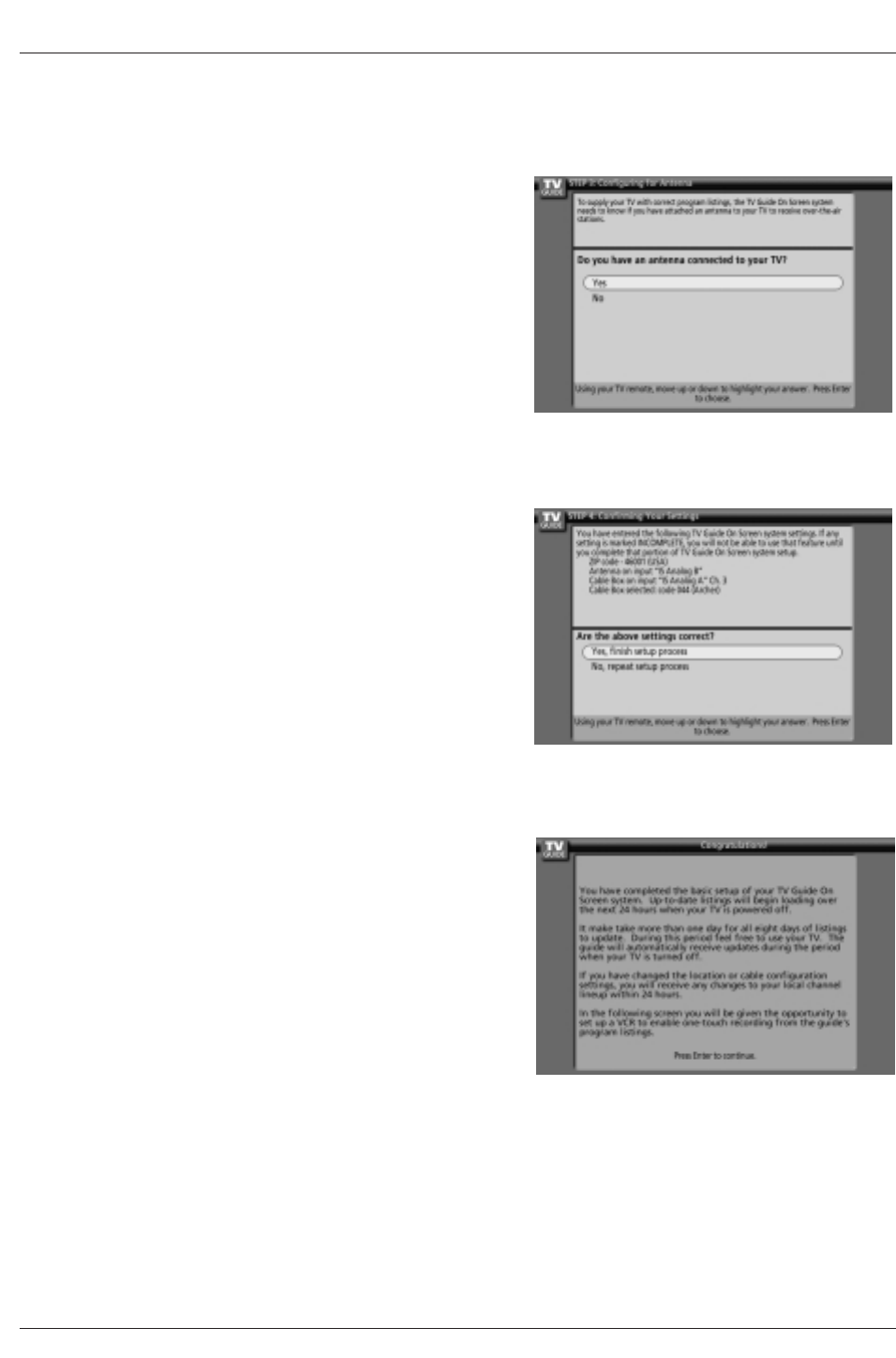
16. Screen 14: Congratulations
•Press ENTER to display Screen 15.
15. Screen 13: Are your basic settings correct?
•If you select Yes, you see Screen 14.
•If you select No, you see Screen 1.
14. Screen 12: Do you have an antenna connected?
•If you select Yes, you see Screen 13.
Note: If you selected No in Screen 3 then you must
select Yes in this screen to receive a channel
lineup and listings.
•If you select No, you see Screen 13.
DLP Projection TV
Installation
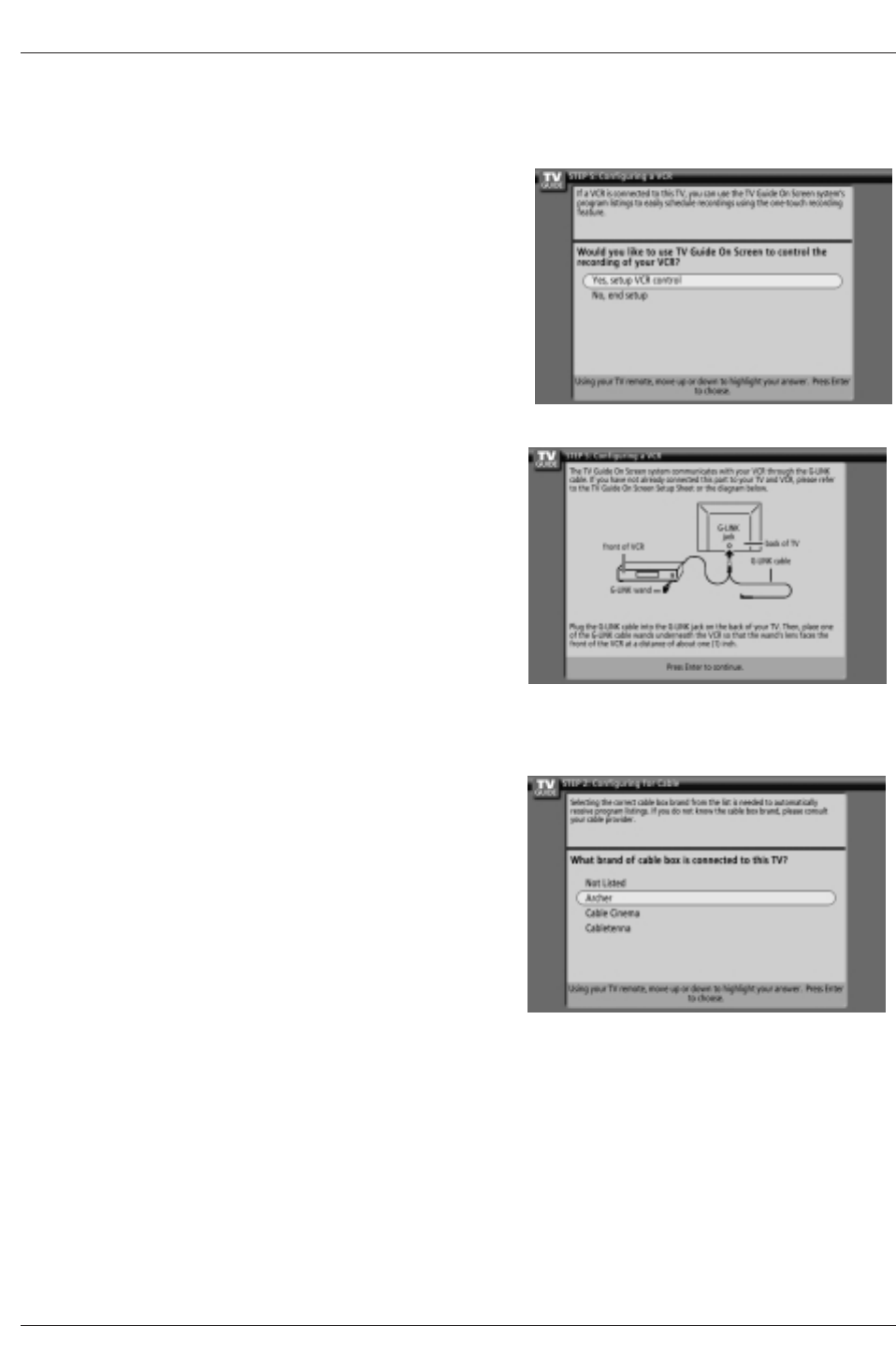
19. Screen 17: VCR Brand Name
•Use the D/ Ebuttons to select the brand of the recording device.
•Press ENTER, and you see Screen 18.
18. Screen 16: VCR Configuration Diagram
•This screen shows the correct way to install the G-LINK Cable from
the back of the TV to the Recording device.
Make sure the G-LINK Cable is properly installed.
•Press ENTER, and you see Screen 17.
17. Screen 15: Is a VCR Connected?
•If you select Yes, you see Screen 16.
•If you select No, you see Screen 21.
Owner’s Manual 9
Installation
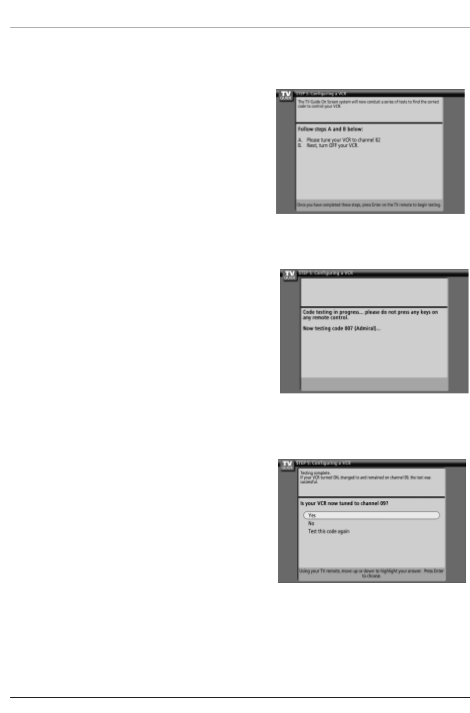
20. Screen 18: VCR Preparation
Follow the on-screen instructions, and press ENTER to display Screen
19.
21. Screen 19: VCR Code Testing
When testing is done, Screen 20 displays automatically.
22. Screen 20: VCR Tuned to Channel 9?
•If you select Yes, you see Screen 21.
•If you select No, a different code is tested in Screen 19.
Note : Many VCRs require testing more than one code.
•If you select Test this code again, the same code is tested again in
Screen 19.
DLP Projection TV
Installation
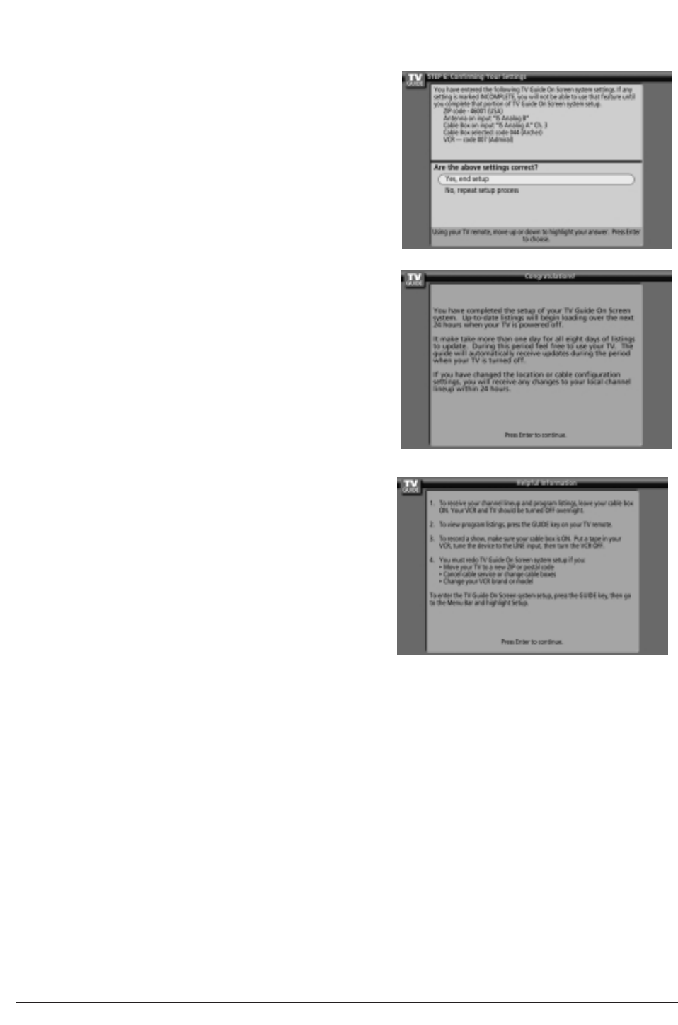
23 Screen 21: Confirming Your Settings
Verify the Setup information is correct.
If it is, select Yes, end setup, and you see Screen 22.
If it is not, select No, repeat setup process, and you see Screen 1.
24. Screen 22: Congratulations
•You have successfully completed Setup!
•Press ENTER and you see Screen 23.
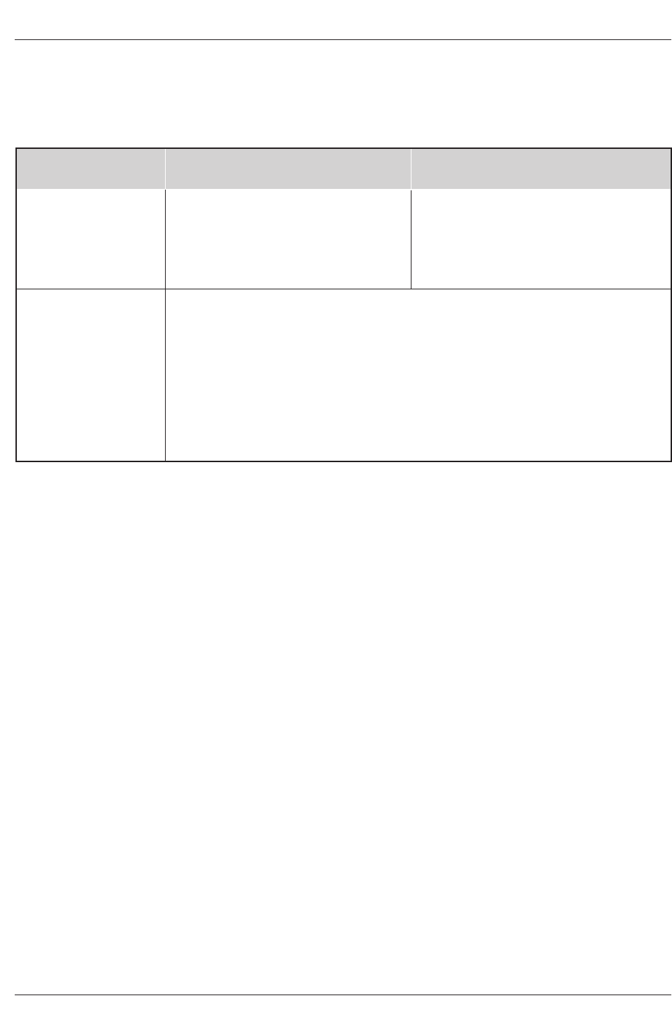
25. Screen 23: Helpful Information
•This screen tells you valuable information on using your Guide.
•Press ENTER to watch TV.
Notes:
The TV Guide On Screen system receives program listings data through your cable or over-the-air video signal. In order to
receive regular program listings, please remember to do the following:
1. Turn OFF your TV when it is not in use. (Do not unplug the power cord.)
2. If you have a Cable box connected, leave it ON.
3. If you have a VCR connected, turn it OFF when not in use. (Do not unplug the power cord.)
4. If you have more than one Cable system in your area, you may be prompted to select which Cable system’s program data to
download. If so prompted, please follow the on-screen instructions.
Product Specification
Owner’s Manual
•The specifications shown above may be changed without prior notice for quality improvement.
Product Specifications
Product Specifications
MODEL
Horizontal Size (inches)
Height (inches)
Depth (inches)
Weight (lbs.)
Power requirement
Television System
Program Coverage
Power Consumption (W)
Antenna
Audio Output (W)
Supplied Accessories
AC120V, 60Hz
NTSC-M, ATSC
VHF 2 ~ 13, UHF 14 ~ 69, CATV 1 ~ 135, CADTV 1 ~ 135. DTV 2 ~ 69
250W
75 ohm External Terminal for VHF/UHF
20Wx2
Remote control, 2 size AA batteries.
DU-52SX40D/52SX4D-UB DU-62SX40D/62SX4D-UB
63.4
40.4
19.5
132.3
55.7
35.5
15.7
82.7