LG Electronics USA GEN21CA AVN Modem Module User Manual
LG Electronics USA AVN Modem Module Users Manual
UserManual.wiki
>
LG Electronics USA
>
GEN21CA User Manual
Users Manual
Navigation menu
Upload a User Manual
Namespaces
Wiki Guide
HTML
PDF
Info
Views
User Manual
Discussion / Help
Navigation
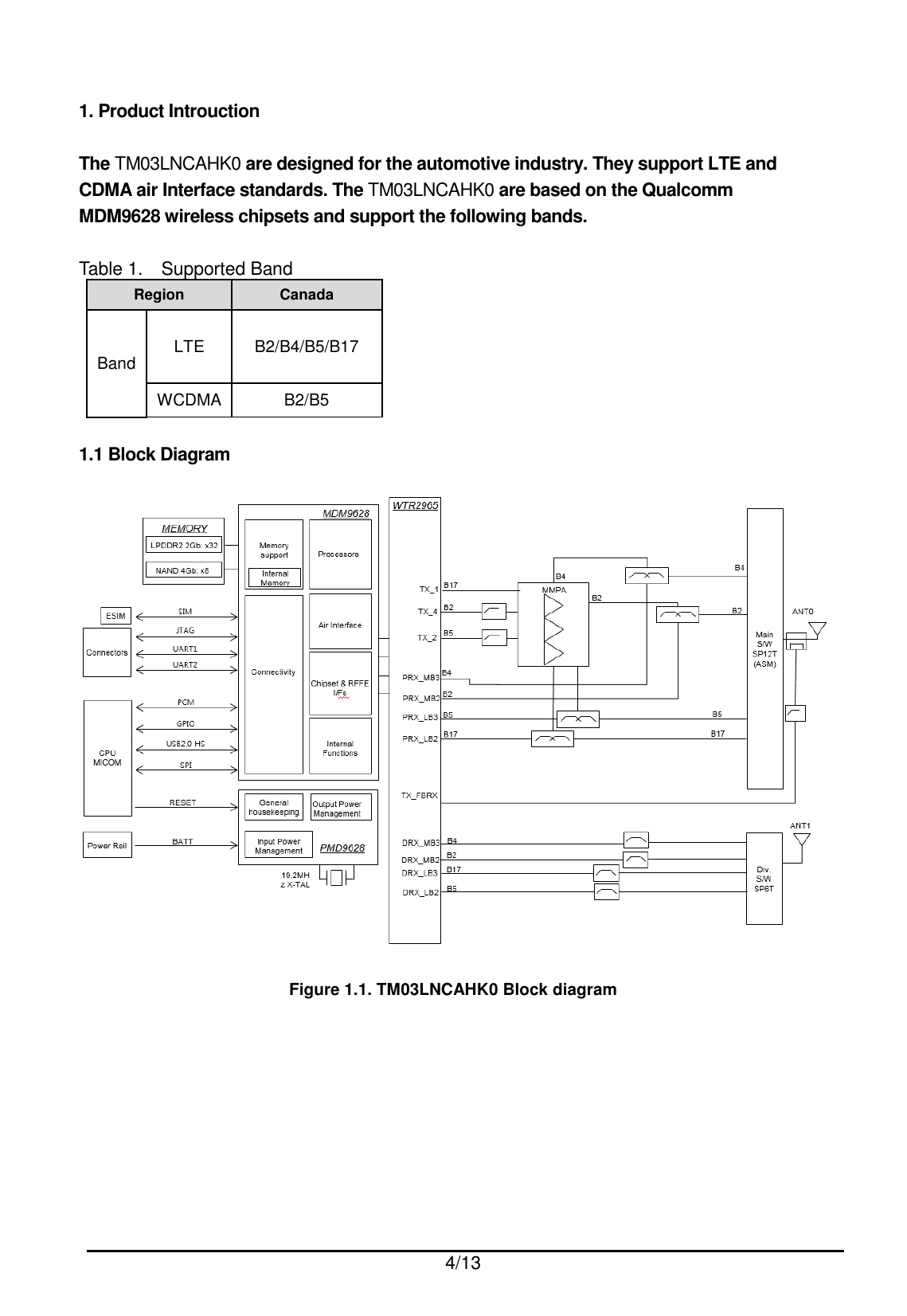
![7/13 1.4.2 Mechanical Drawing 1.4.2.1 Carrier PCB [TOP View] [Bottom View]](https://usermanual.wiki/LG-Electronics-USA/GEN21CA/User-Guide-3293642-Page-7.png)