LG Electronics USA HSTND-3101-G Digital Signage Display User Manual G User s manual
LG Electronics USA Digital Signage Display G User s manual
UserManual.wiki
>
LG Electronics USA
>
HSTND 3101 G User Manual
user manual
Navigation menu
Upload a User Manual
Namespaces
Wiki Guide
HTML
PDF
Info
Views
User Manual
Discussion / Help
Navigation


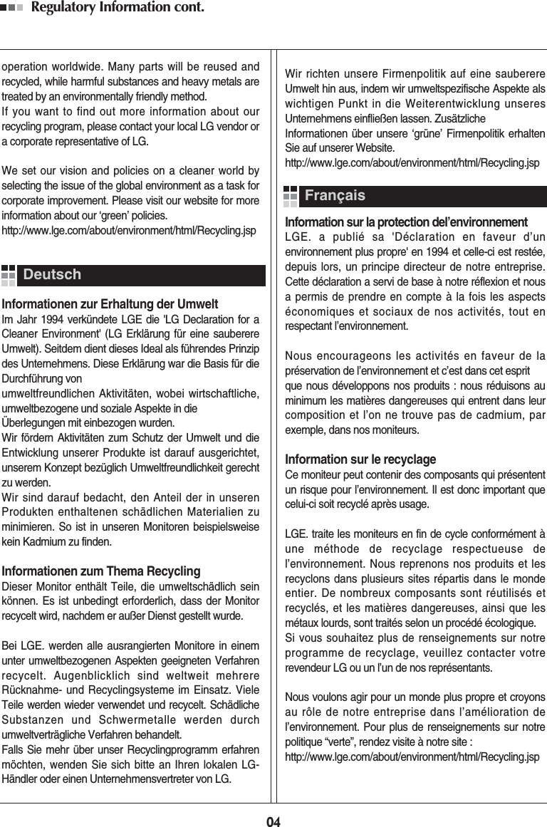
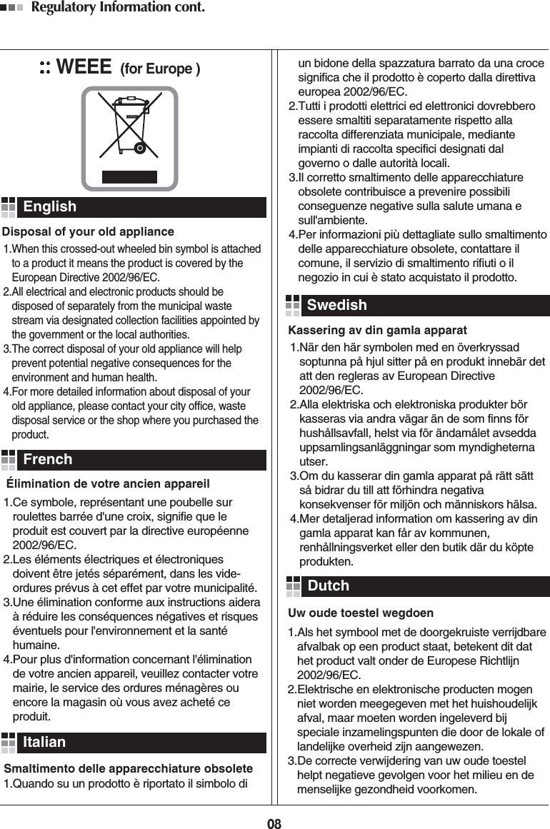
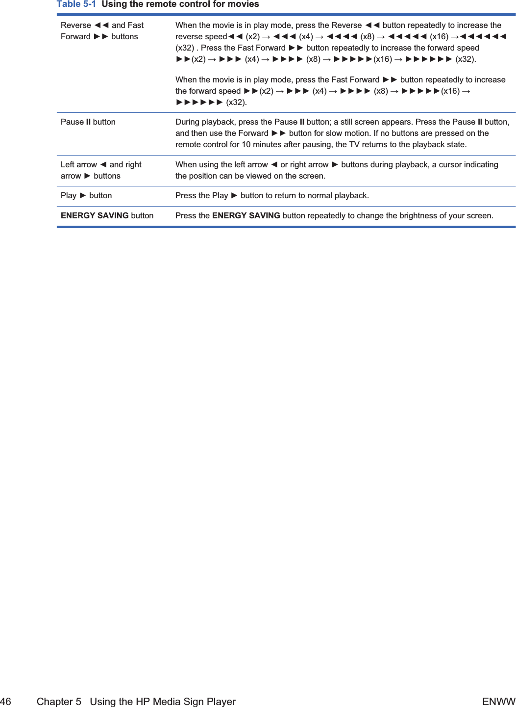
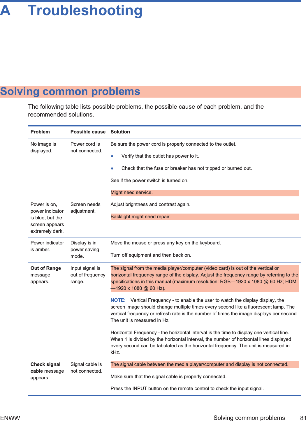
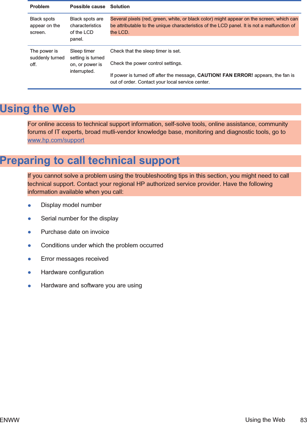
![Maintenance guidelinesTo enhance the performance and extend the life of the display:łDo not open the display cabinet or attempt to service this product yourself. Adjust only thosecontrols that are covered in the operating instructions. If the display is not operating properly orhas been dropped or damaged, contact an authorized HP dealer, reseller, or service provider.łUse only a power source and connection appropriate for this display, as indicated on the label/back plate of the display.łBe sure the total ampere rating of the products connected to the outlet does not exceed thecurrent rating of the electrical outlet, and the total ampere rating of the products connected to thecord does not exceed the rating of the cord. Look on the power label to determine the ampererating (AMPS or A) for each device.łInstall the display near an outlet that you can easily reach. Disconnect the display by graspingthe plug firmly and pulling it from the outlet. Never disconnect the display by pulling the cord.łTurn the display off when not in use. You can substantially increase the life expectancy of thedisplay by using a screen saver program and turning off the display when not in use.CAUTION: [Author note:]Delete this Caution?Burn-in damage might occur on displays that display the same static image on the screen for aprolonged period of time (12 consecutive hours of non-use). To avoid burn-in image damage onthe display screen, you should always activate a screen saver application or turn off the displaywhen it is not in use for a prolonged period of time or cycle between 5 minutes of staticinformation and 10 seconds of a moving image. Image retention is a condition that might occuron all LCD screens. Screen burn-in is not covered under the HP warranty.łSlots and openings in the cabinet are provided for ventilation. These openings must not beblocked or covered. Never push objects of any kind into cabinet slots or other openings.łDo not drop the display or place it on an unstable surface.łDo not allow anything to rest on the power cord. Do not walk on the cord.łKeep the display in a well-ventilated area, away from excessive light, heat or moisture.łWhen removing the display base, you must lay the display face down on a soft area to prevent itfrom getting scratched, defaced, or broken.4 Chapter 2 Safety and maintenance guidelines ENWW2ndDraft](https://usermanual.wiki/LG-Electronics-USA/HSTND-3101-G/User-Guide-1381578-Page-17.png)
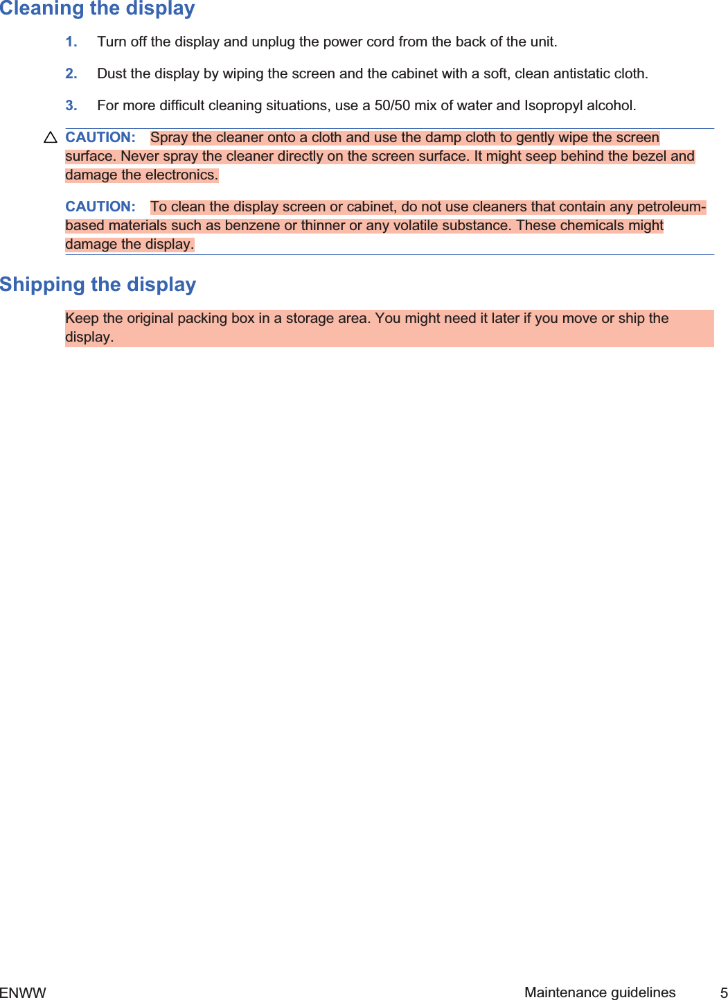
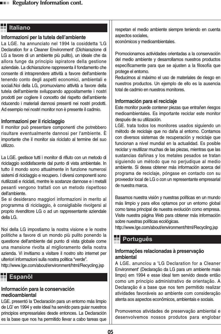
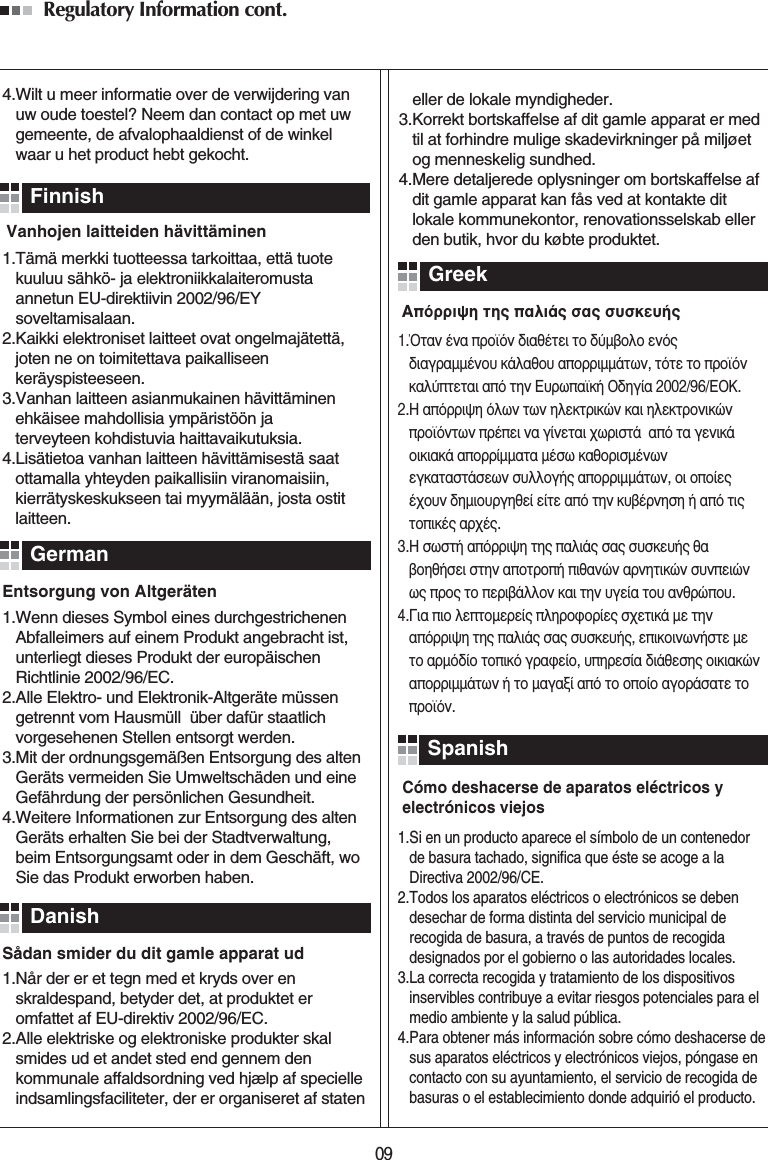
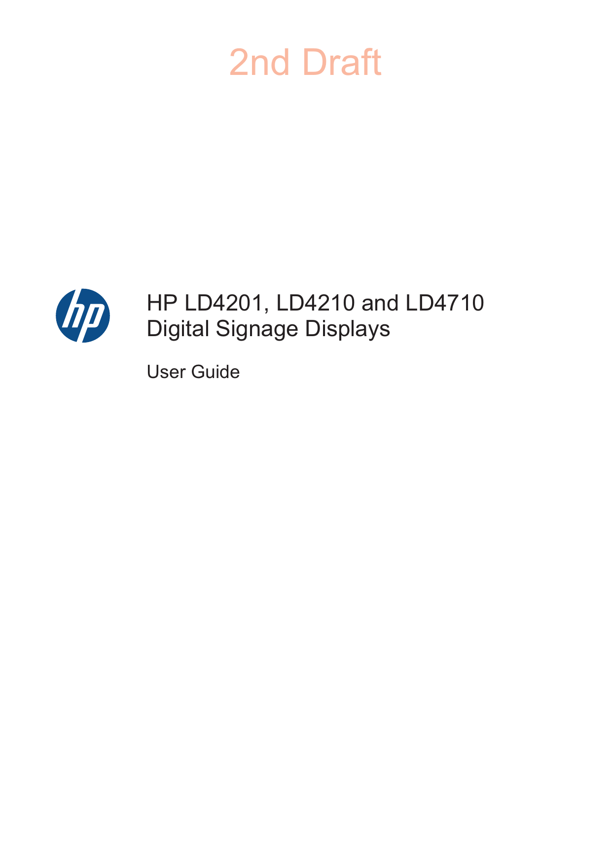
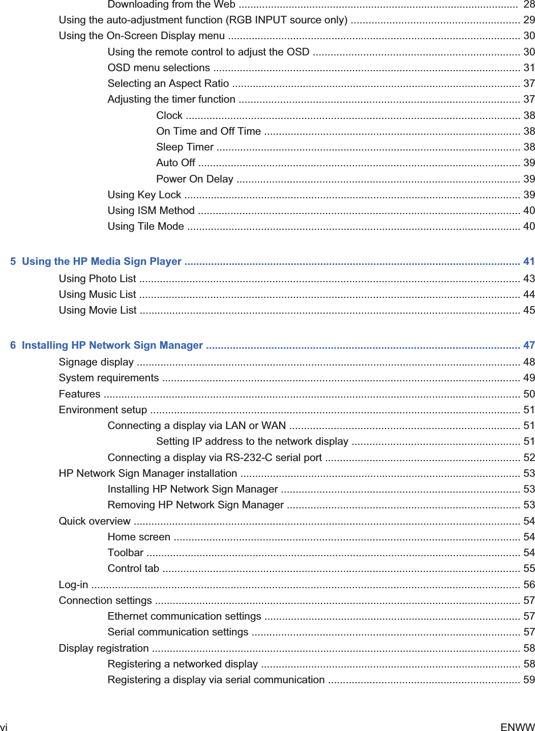
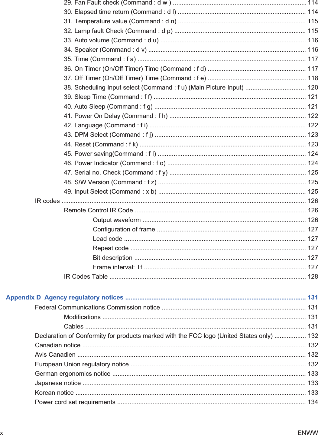
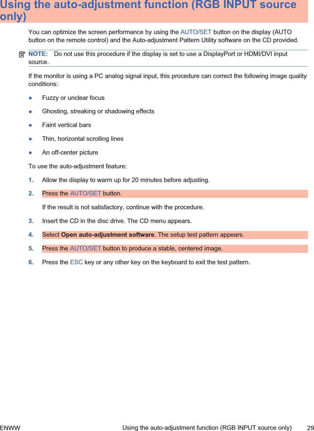
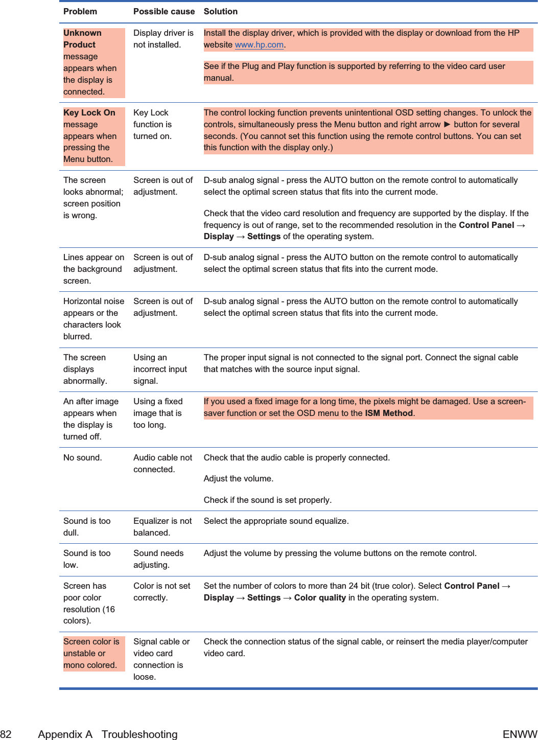
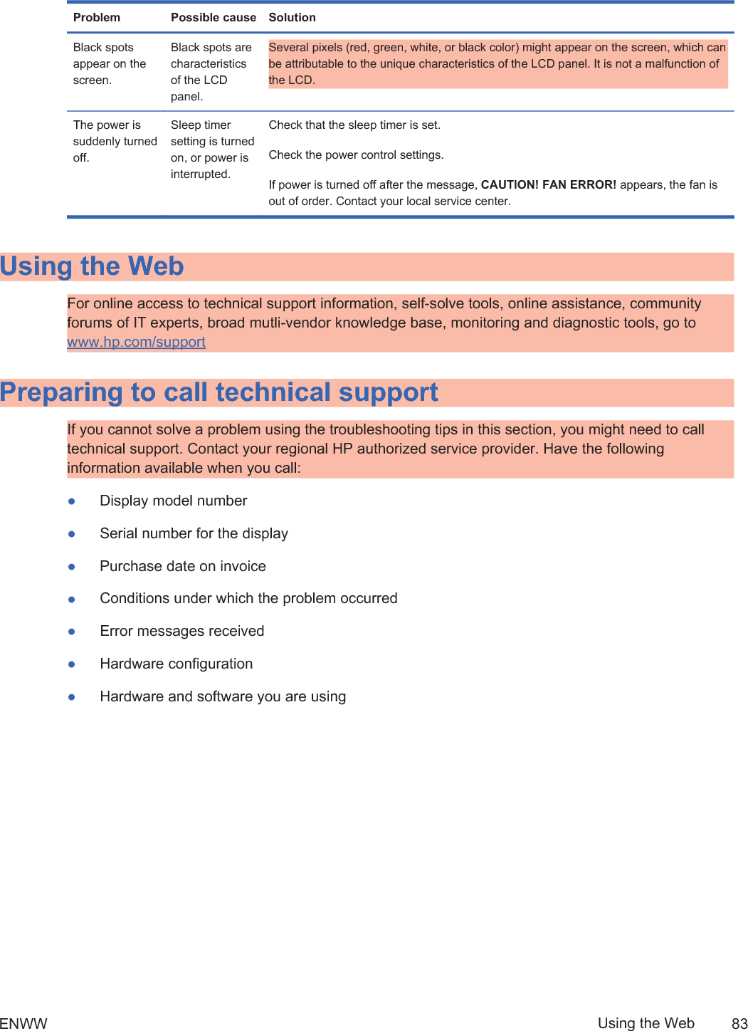
![3 Setting up the displayTo set up the display, ensure that the power is turned off to the display, media player/computersystem, and other attached devices, and then follow the instructions below.Installing the stand (sold separately)1. [Author note:]Update this stand section to show differences between the 42 and 47models. David N. as the screw measurements as 42” =33mm (1 5/16”) and 47”=17mm (5/8“) with a washer, but Brian D. has LGE guide that says 42”=30mm and 47”=10mm.Take the parts for the stand out of the box.łFor the HP LD4201 and LD4210—four screws M4 x 33 mm ( in) (1) and stand (2)łHP LD4710—four screws M4 x 17 mm ( in) (1) and stand (2)Figure 3-1 Stand accessory contents1 21 2ENWW Installing the stand (sold separately) 72ndDraft](https://usermanual.wiki/LG-Electronics-USA/HSTND-3101-G/User-Guide-1381578-Page-20.png)
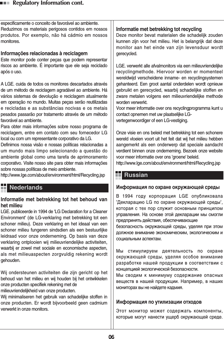
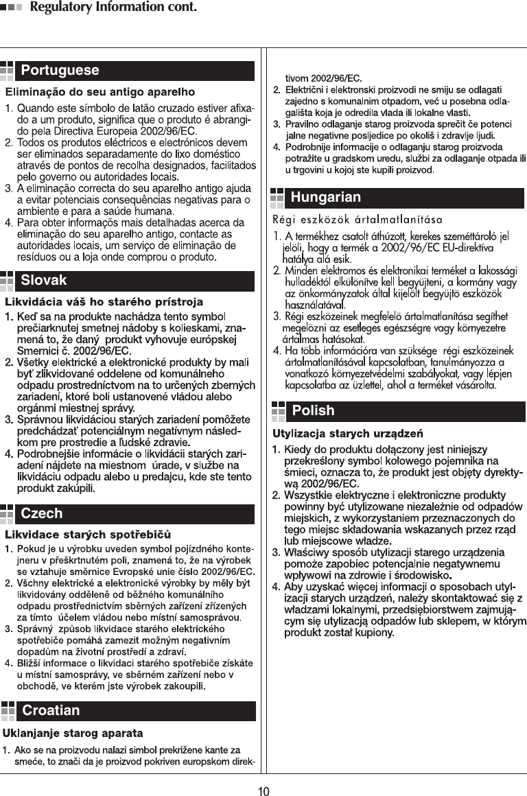
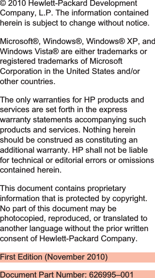
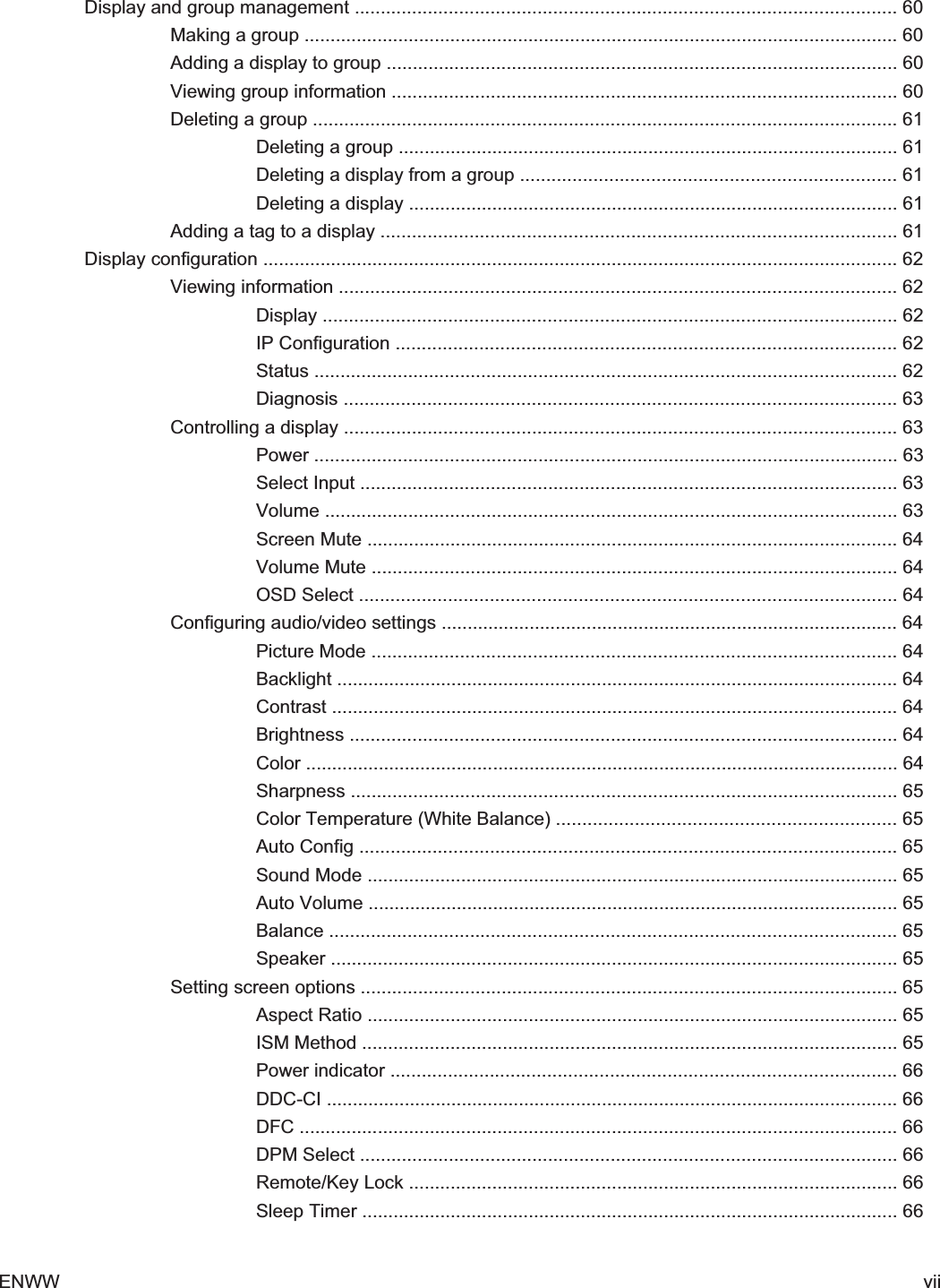
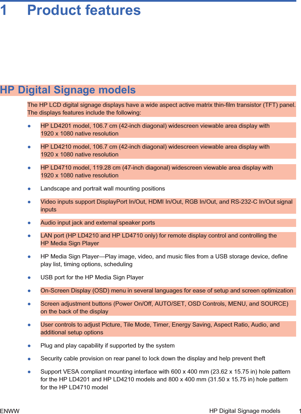
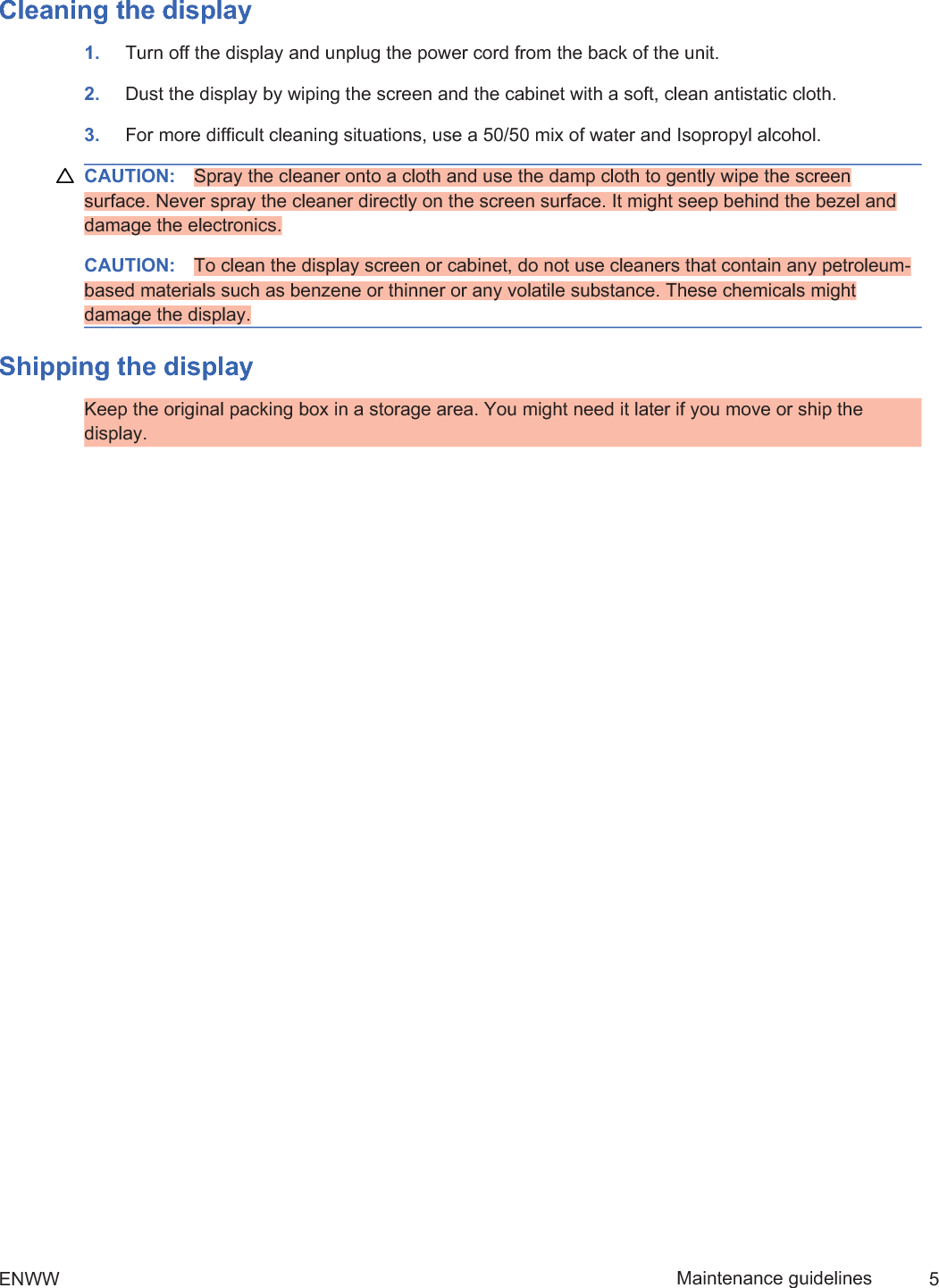
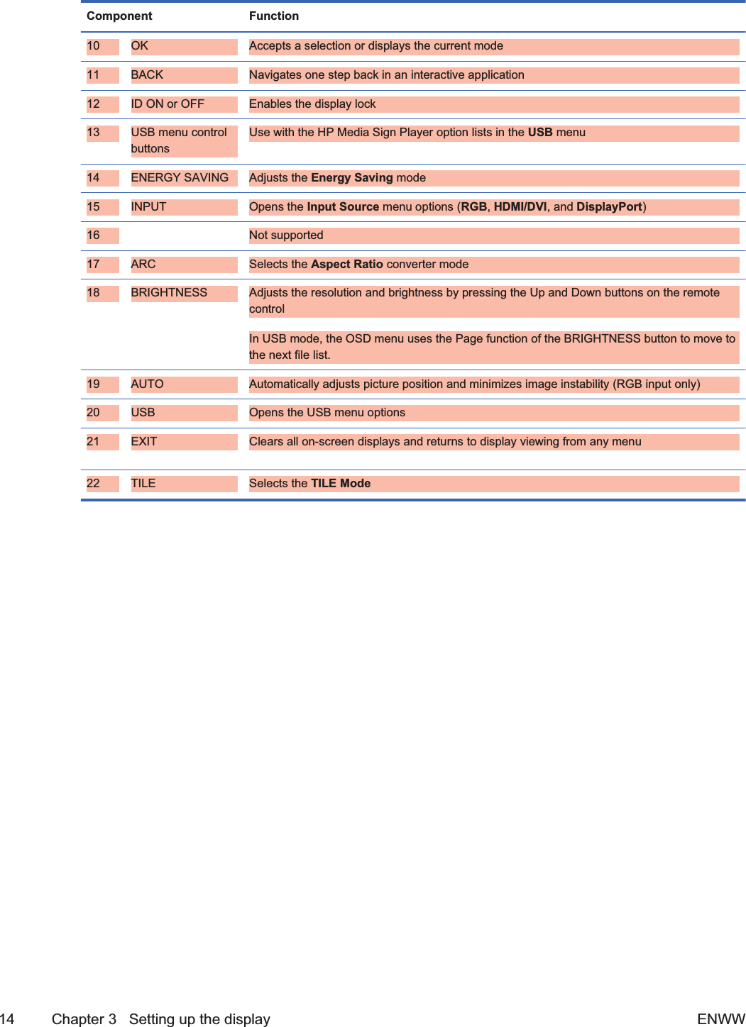
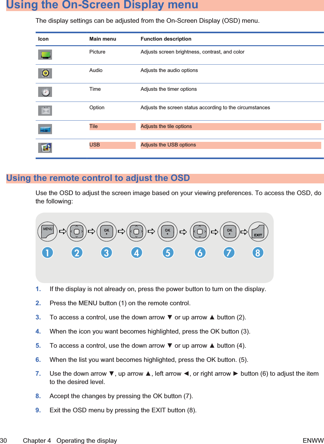
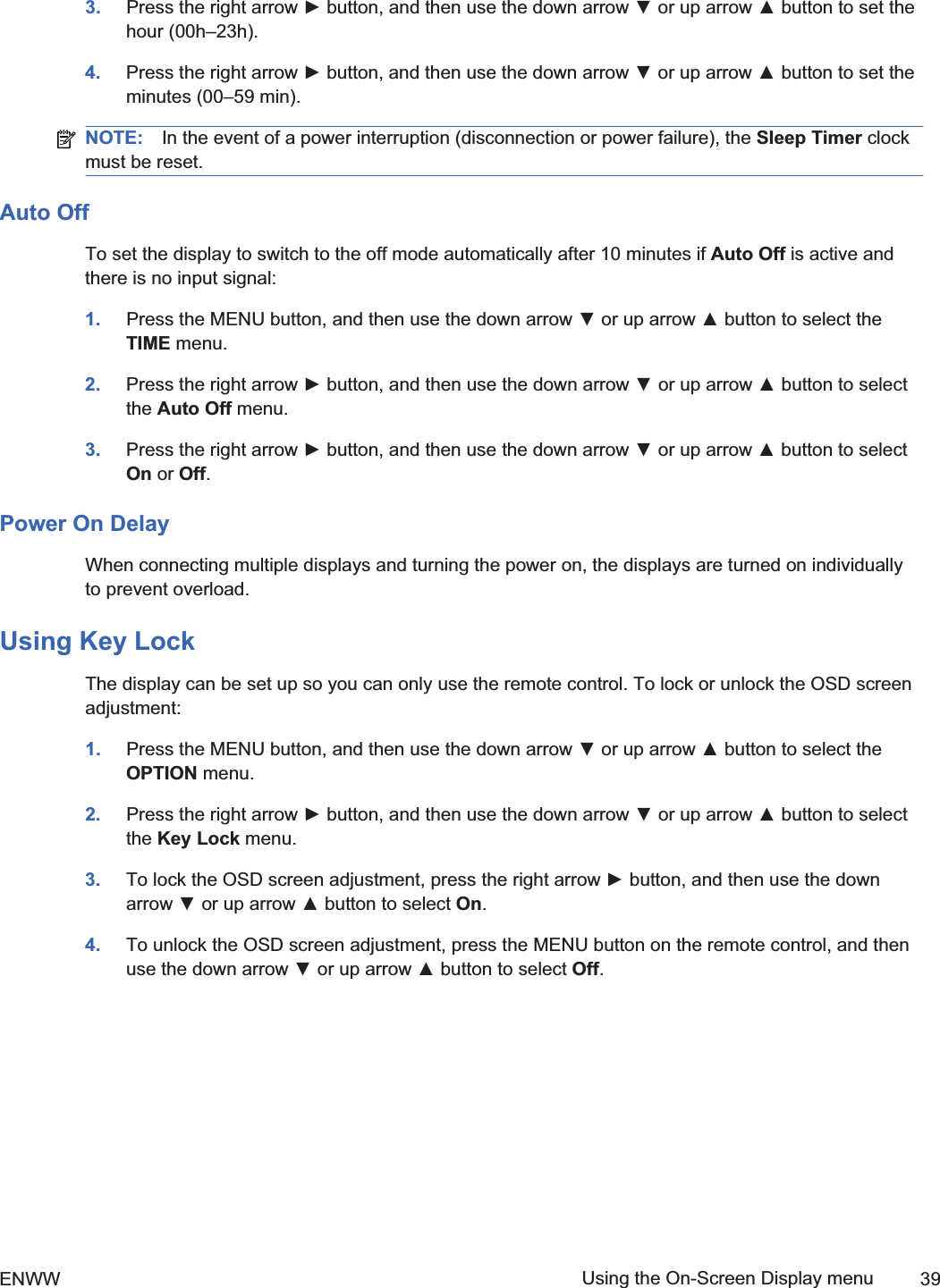
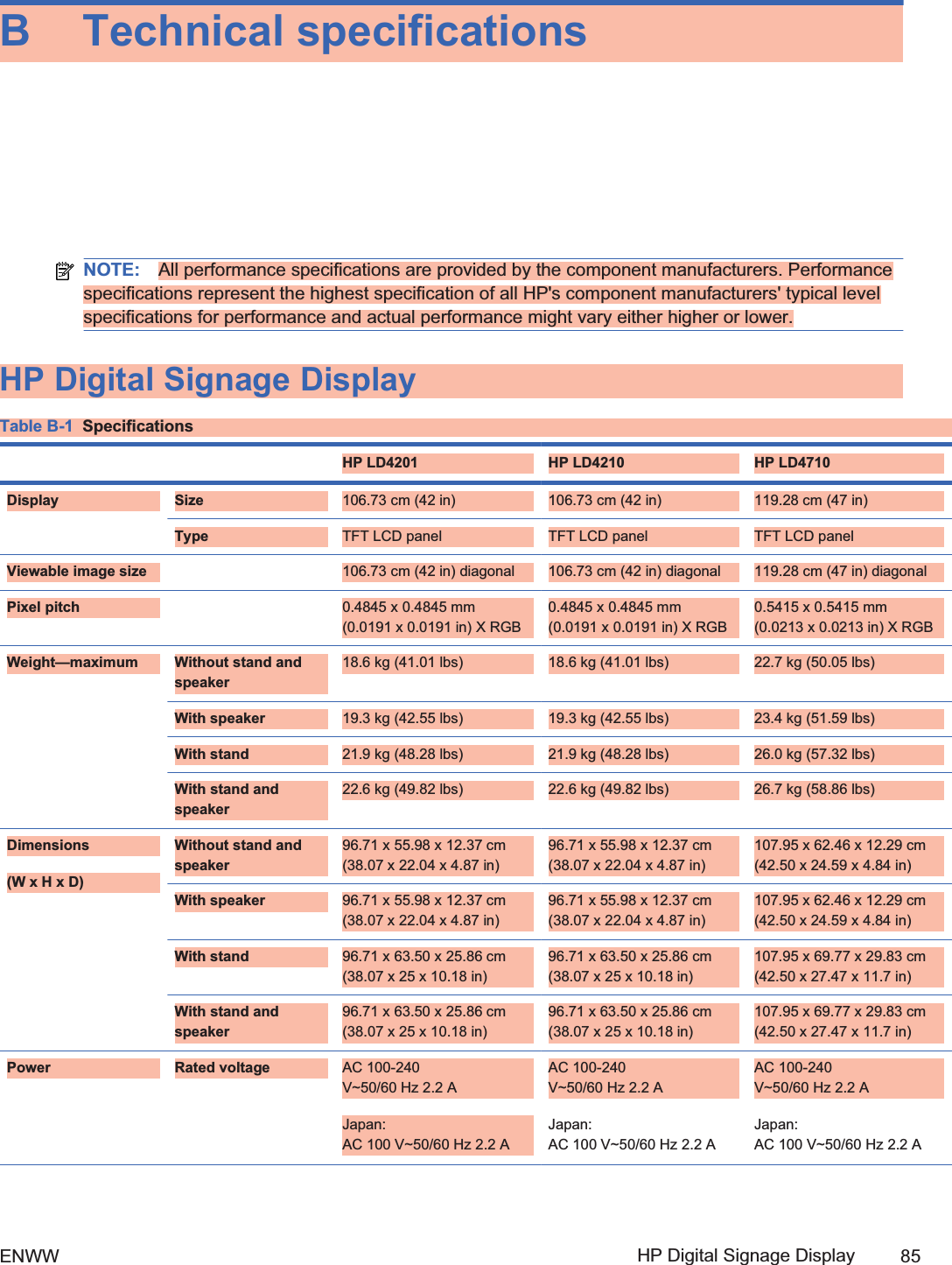
![Identifying remote control buttonsFigure 3-11 Remote control buttons[Author note:]Graphic is being updated — component 4 and16 are not supported and component 20 is now USB instead of S.MenuPAGEINPUTENERGYSAVINGMARKARCONOFF. , ! ABC DFGGHI JKL MNOPQRS TUV- * #WXYZOKUSBMONITORPSMAUTOMUTEBRIGHTNESSMENUIDBACK TILEON OFFEXIT12381112139106745141518202122161719Component Function1Power on/off Turns the display on from standby or off to standby2MONITOR ON orOFFTurns the display on and off3Number andalphabetTypes numbers and alphabet letters4 Not supported5Volume up (+) ordown (-)Adjusts the volume6PSM Selects the Picture Status Mode7MUTE Turns the sound on or off8MENU Selects a menu or clears all on-screen displays and returns to display viewing from any menu9Up/down/left/rightarrowsAllows navigation of the On-Screen Display menus and adjustment of the system settingsENWW Using the remote control 132ndDraft](https://usermanual.wiki/LG-Electronics-USA/HSTND-3101-G/User-Guide-1381578-Page-26.png)
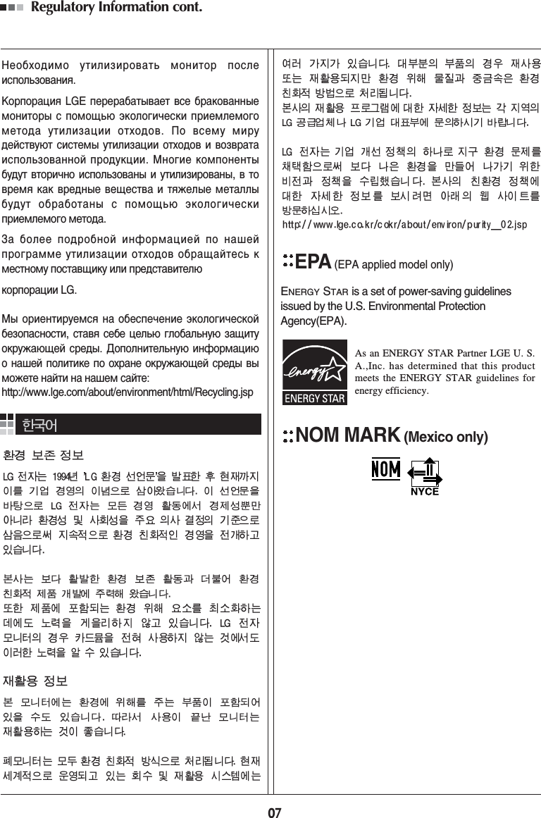
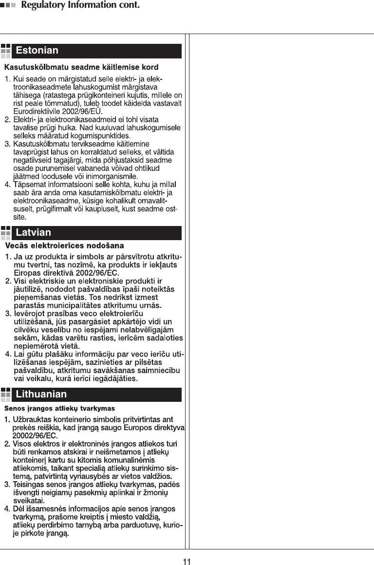
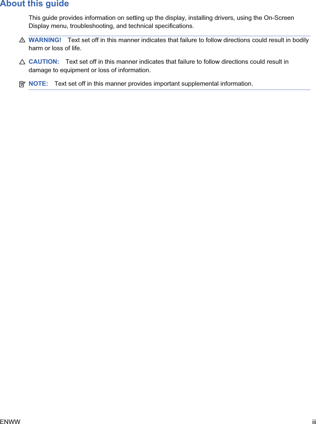
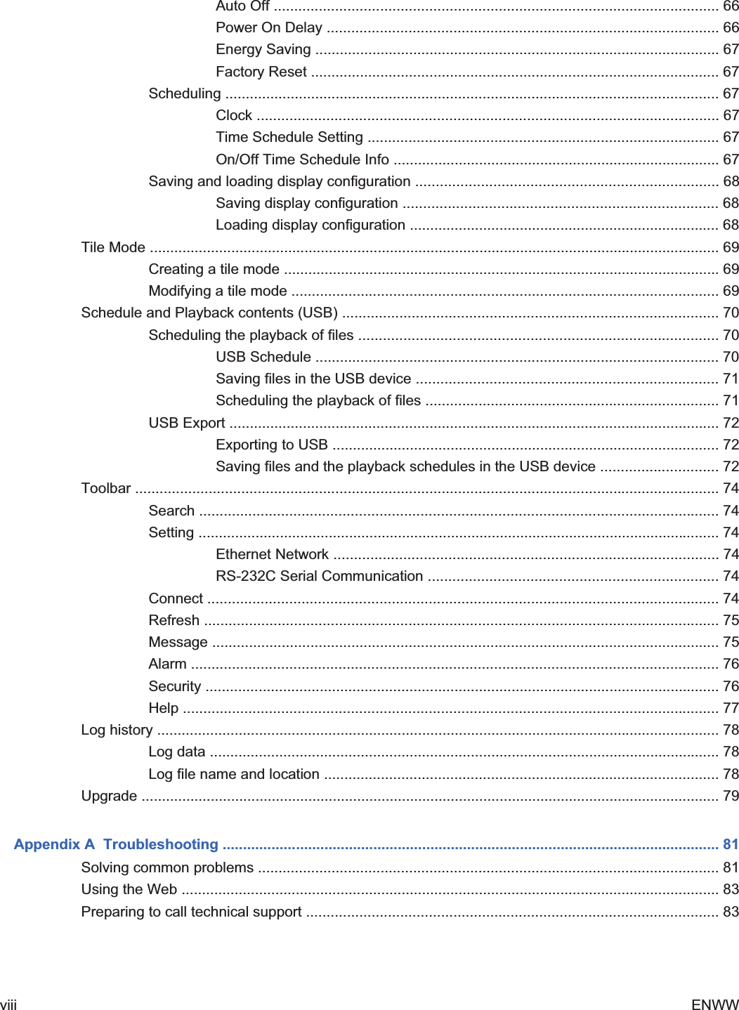
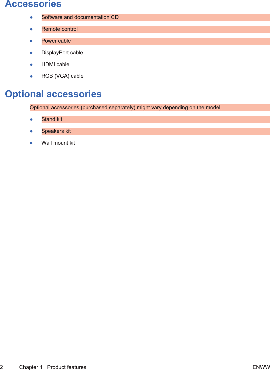
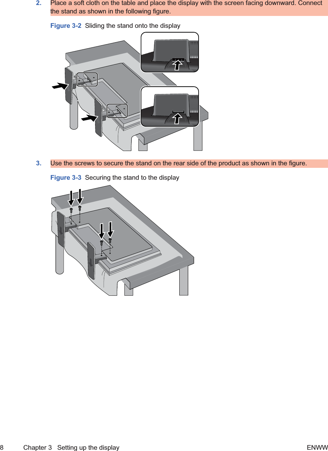
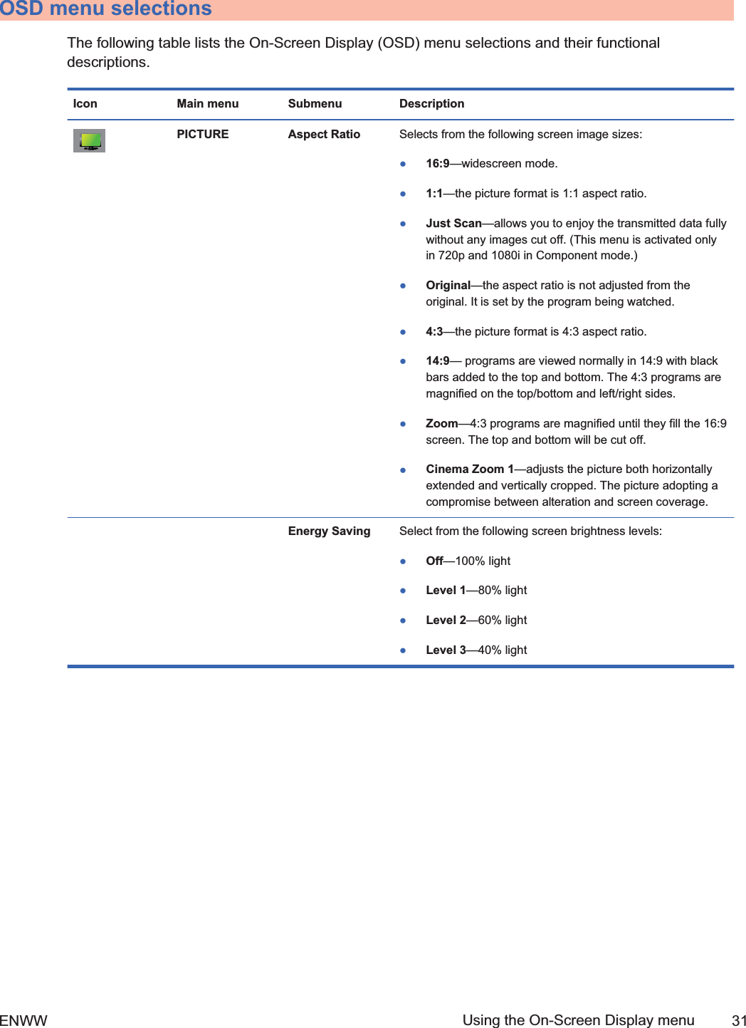
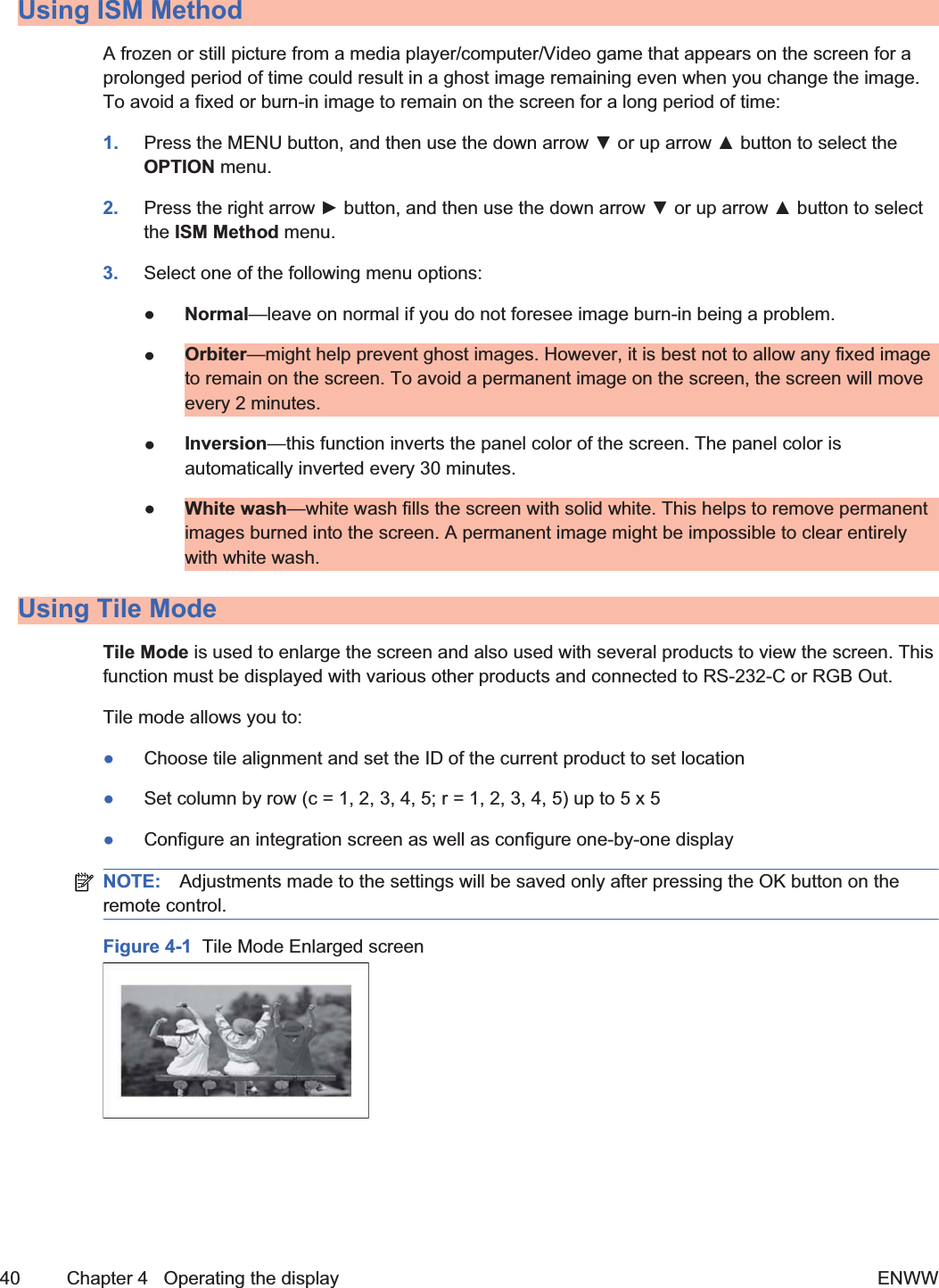
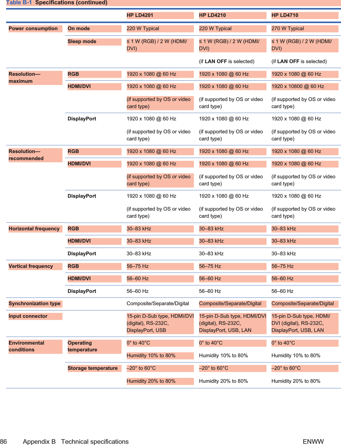
![Identifying display componentsFigure 3-12 Display components[Author note:]Update graphic —need new front and backcomponent graphics with callouts.1 2 3 4 576Component Function1SOURCE Toggles between video inputs:łHDMI/DVI - Digital signalłRGB - 15-pin D-Sub analog signalłDisplayPort2MENU Opens or closes the OSD (On-Screen Display) menu screen.3 OSD select/adjust buttons Selects an OSD menu icon or adjusts the settings in the OSD screen.Down arrow ź and up arrow Ÿ buttons adjust up and downLeft arrow Ż and right arrow Ź buttons adjust the volume4AUTO/SET When the OSD window is closed, the auto-adjustment feature to optimize thescreen image is activated.When the OSD window is open, press to select a menu item or save changes.5 Power Press to turn on the power. Press again to turn it off.6 IR receiver Receives signals from the remote control.7 LED indicator light Lights up blue when the display operates normally (on mode). If the display is insleep (Energy Saving) mode, the indicator color changes to amber.ENWW Identifying display components 15Draft](https://usermanual.wiki/LG-Electronics-USA/HSTND-3101-G/User-Guide-1381578-Page-28.png)
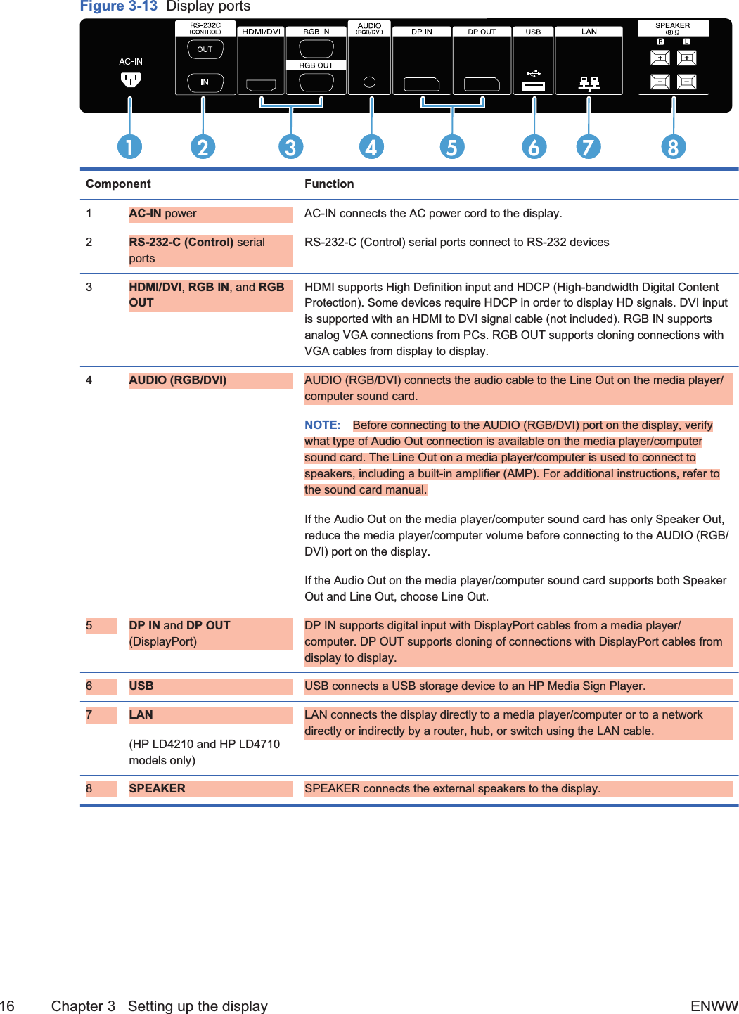
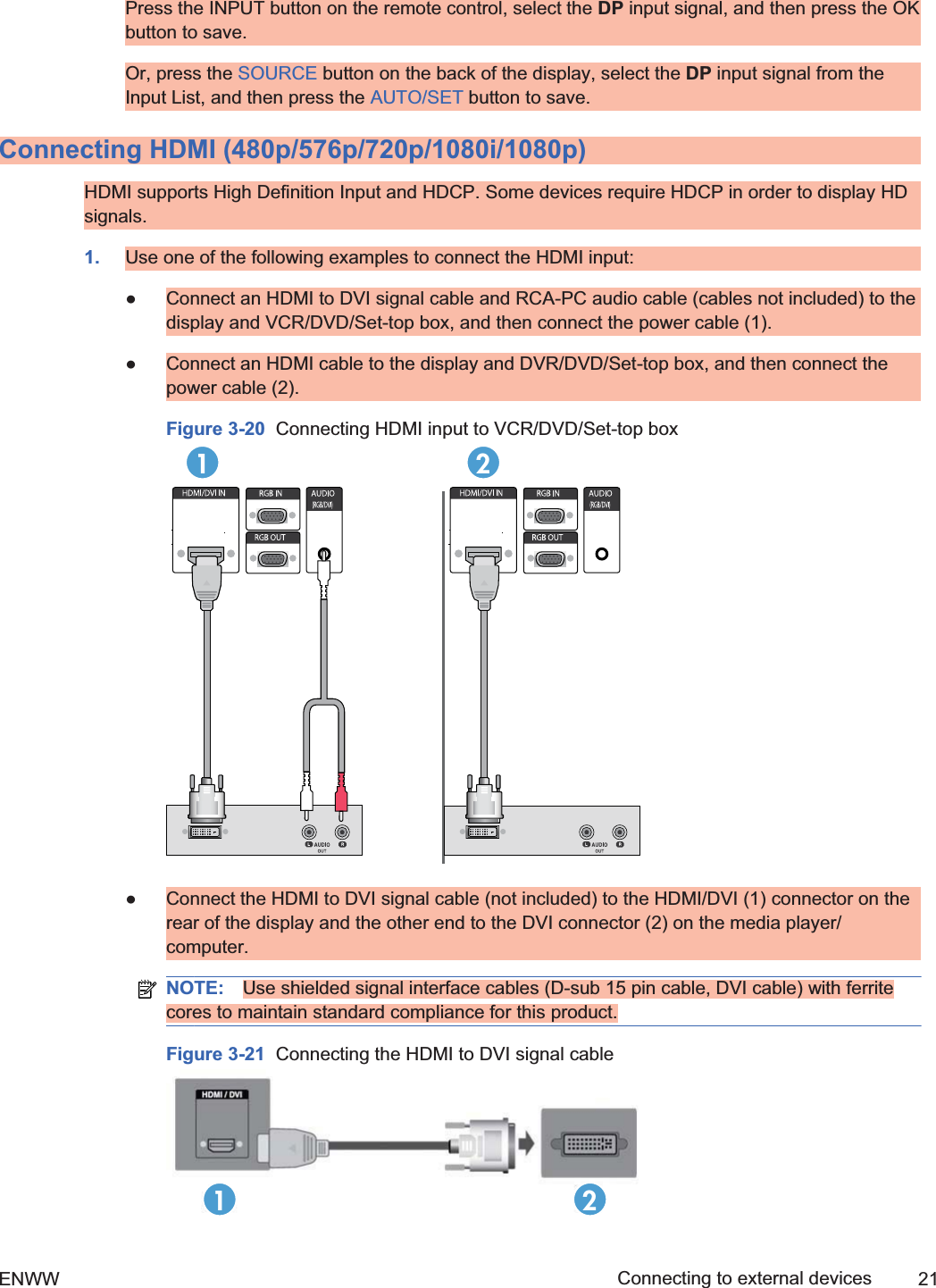
![Connecting to external devices1. Be sure that the display, media player/computer, and all attached devices are turned off.2. Connect the signal input cable.For additional information, see one of the following signal input cable sections:łConnecting RGB on page 20łConnecting DisplayPort (480p/576p/720p/1080i/1080p) on page 20łConnecting HDMI (480p/576p/720p/1080i/1080p) on page 21łConnecting LAN (HP LD4210 and HP LD4710 only) on page 223. Connect the audio cable (sold separately) to the Audio (RGB/DVI) (1) connector on the rear ofthe display and the other end to the Line Out port (2) on the media player/computer if the videosignal connection is from either a RGB (VGA) or DVI connector on the media player/computer.Figure 3-15 Connecting the audio12NOTE: The ferrite core can be used to reduce electromagnetic waves when connecting anaudio cable. As shown in the image, fit the ferrite core to the audio cable. The ferrite core needsto be separated from the mold by 5 cm (2 in).4. Connect the AC power cord to the AC-IN connector (1) on the rear of the display and the otherend to an electrical outlet (2). Before connecting the power cord, please read the power-cordsafety precautions in the Important safety information on page 3.[Author note:]I have removed the Warning message that appeared below this step,because it was identical to the Warning in the “Important safety information” section;instead, I have referenced this safety section that contains the Warning message. Is thisok?Figure 3-16 Connecting the power cord[Author note:]Update graphic —Needs a newgraphic of the power cord.1218 Chapter 3 Setting up the display ENWW2ndDraft](https://usermanual.wiki/LG-Electronics-USA/HSTND-3101-G/User-Guide-1381578-Page-31.png)
![5. Turn on power to the display by pressing the power button.Figure 3-17 Power button[Author note:]Update graphic-Needs a new graphic of front ofdisplay.6. Turn on the media player/computer.7. Select an input signal.Press the INPUT button on the remote control to open the Input List, select the appropriateinput signal (RGB, HDMI/DVI, DP), and then press the OK button to save your change.Or, press the SOURCE button on the back of the display, and then press the AUTO/SET buttonto save your change.NOTE: If connecting more than one input source, connect the signal cables [HDMI/DVI, RGB(VGA), and DisplayPort] to each media player/computer. Press the INPUT button on the remotecontrol to select the input to view.ENWW Connecting to external devices 19Draft](https://usermanual.wiki/LG-Electronics-USA/HSTND-3101-G/User-Guide-1381578-Page-32.png)
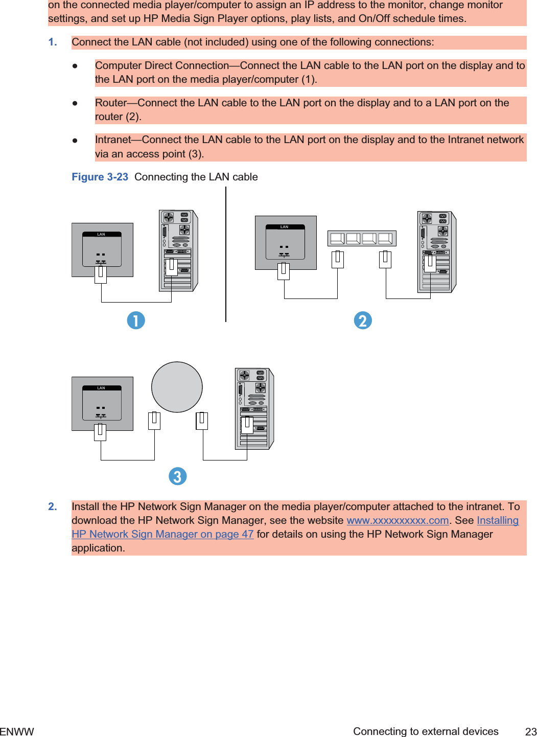
![łConnect the HDMI to HDMI signal cable (not included) to the HDMI/DVI (1) connector onthe rear of the display and the other end to the HDMI connector (2) on the media player/computer.Figure 3-22 Connecting the HDMI to HDMI signal cable[Author note:]Create graphic forHDMI to HDMI?2. Select an input signal.Press the INPUT button on the remote control, select the HDMI/DVI input signal, and then pressthe OK button to save.Or, press the SOURCE button on the back of the display, select the HDMI/DVI input signal, andthen press the AUTO/SET button to save.Connecting LAN (HP LD4210 and HP LD4710 only)The LAN input on the display can connect to a media player/computer, a router (switch), or anIntranet. A LAN connection with the display establishes communication between your media player/computer and the display, which enables the use of the HP Network Sign Manager program running22 Chapter 3 Setting up the display ENWW2ndDraft](https://usermanual.wiki/LG-Electronics-USA/HSTND-3101-G/User-Guide-1381578-Page-35.png)
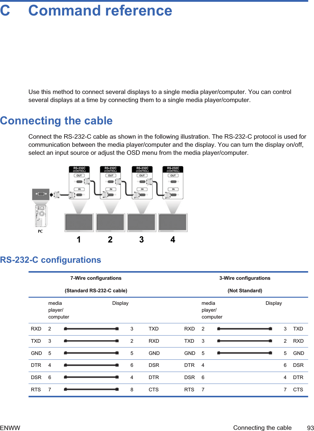
![Connecting daisy chain displaysMultiple monitors (up to 25) can be connected in a daisy chain (connect several monitors together intile mode) to a computer using DisplayPort IN/OUT or with the combination of RGB IN/OUT andRS-232-C IN/OUT ports on the display.To connect displays in a daisy chain, the displays must all be connected with the same input/outputsource (DisplayPort IN/OUT or RGB IN/OUT and RS-232-C IN/OUT) as shown in the figures below.łTo daisy chain displays for video, use DisplayPort IN/OUT connections or RGB IN/OUTconnections.łTo daisy chain for both video and display command and control, use DisplayPort IN/OUT plusRS-232-C IN/OUT or RGB IN/OUT plus RS-232-C IN/OUT.NOTE: The number of displays that can be connected by daisy chain to one media player/computermight vary depending on the signal status and cable loss. If the signal status is good, and there is nocable loss, it is possible to connect up to twenty-five displays in a daisy chain from one media player/computer.To connect multiple displays in a daisy chain, connect the input signal cable from the media player/computer to the first display in the daisy chain and connect the subsequent displays, using the sameinput signal cables, from the OUT port to the IN port of the next display, as shown in the figuresbelow, until all the displays are connected together.Figure 3-24 Daisy chain connection—RGB for video input signal123 4Figure 3-25 Daisy chain connection—RGB for video input signals and RS-232-C for displaycommand and control[Author note:]Create graphic for daisy chain RGB and RS-232–C?Figure 3-26 Daisy chain connection—DisplayPort for video input signalDisplay InDisplay OutDisplay InDisplay OutDisplay InDisplay OutDisplay InDisplay Out12 3 424 Chapter 3 Setting up the display ENWW2ndDraft](https://usermanual.wiki/LG-Electronics-USA/HSTND-3101-G/User-Guide-1381578-Page-37.png)
![Figure 3-27 Daisy chain connection—DisplayPort for video input signal and RS-232-C for displaycommand and control[Author note:]Create graphic for daisy chain DisplayPort and RS-232–C?ENWW Connecting daisy chain displays 252ndDraft](https://usermanual.wiki/LG-Electronics-USA/HSTND-3101-G/User-Guide-1381578-Page-38.png)
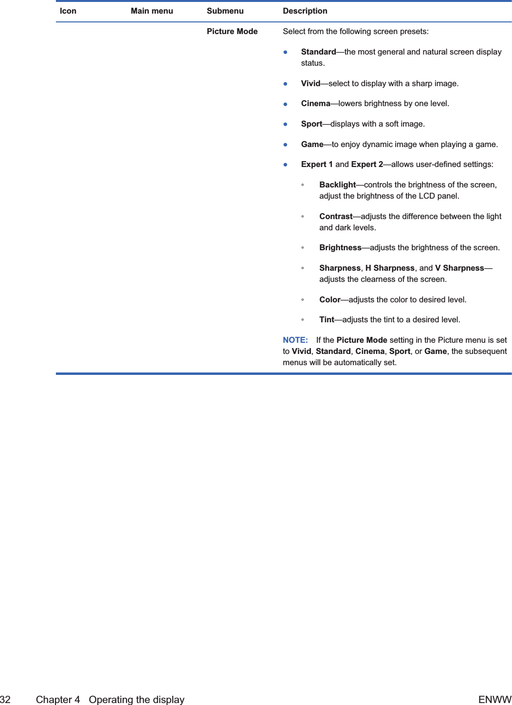
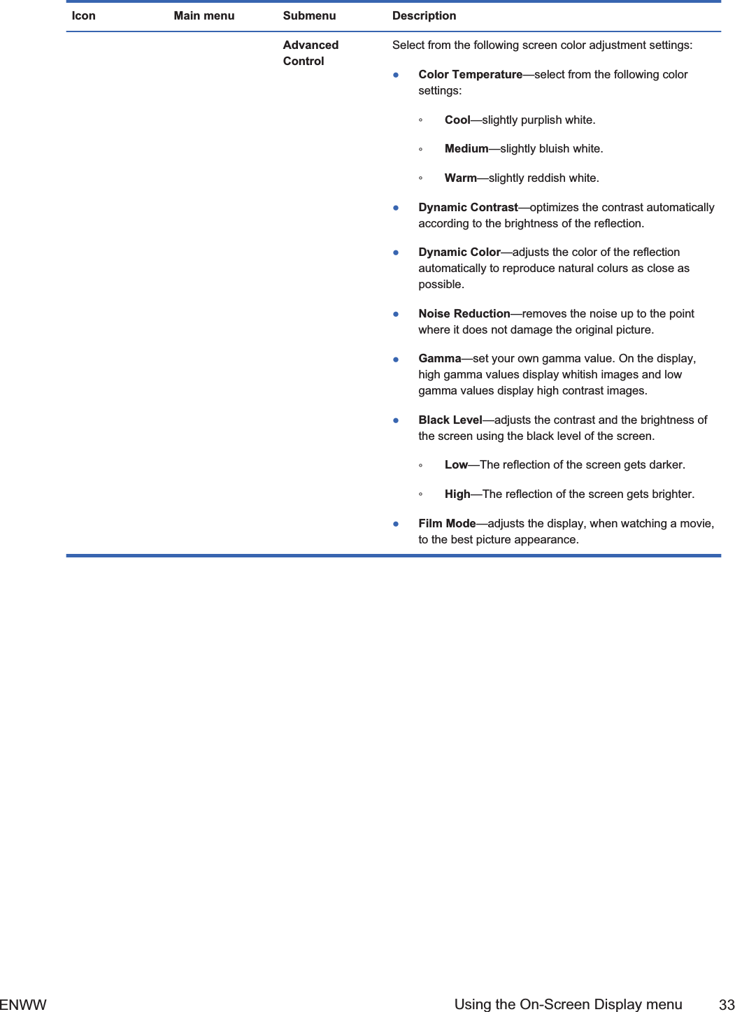
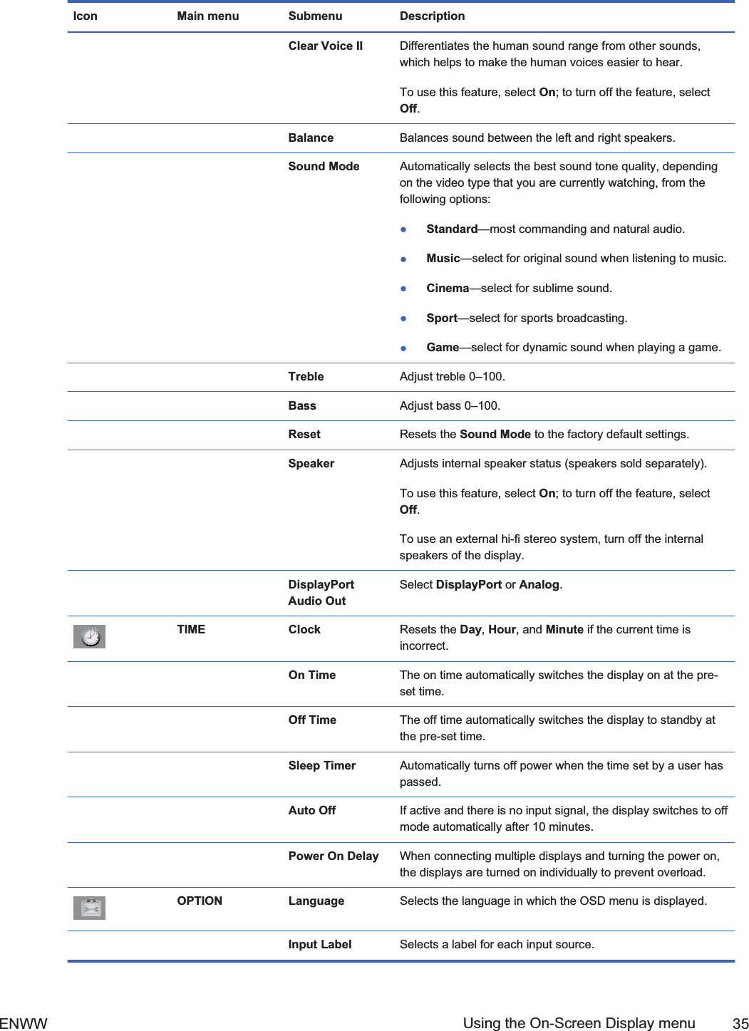
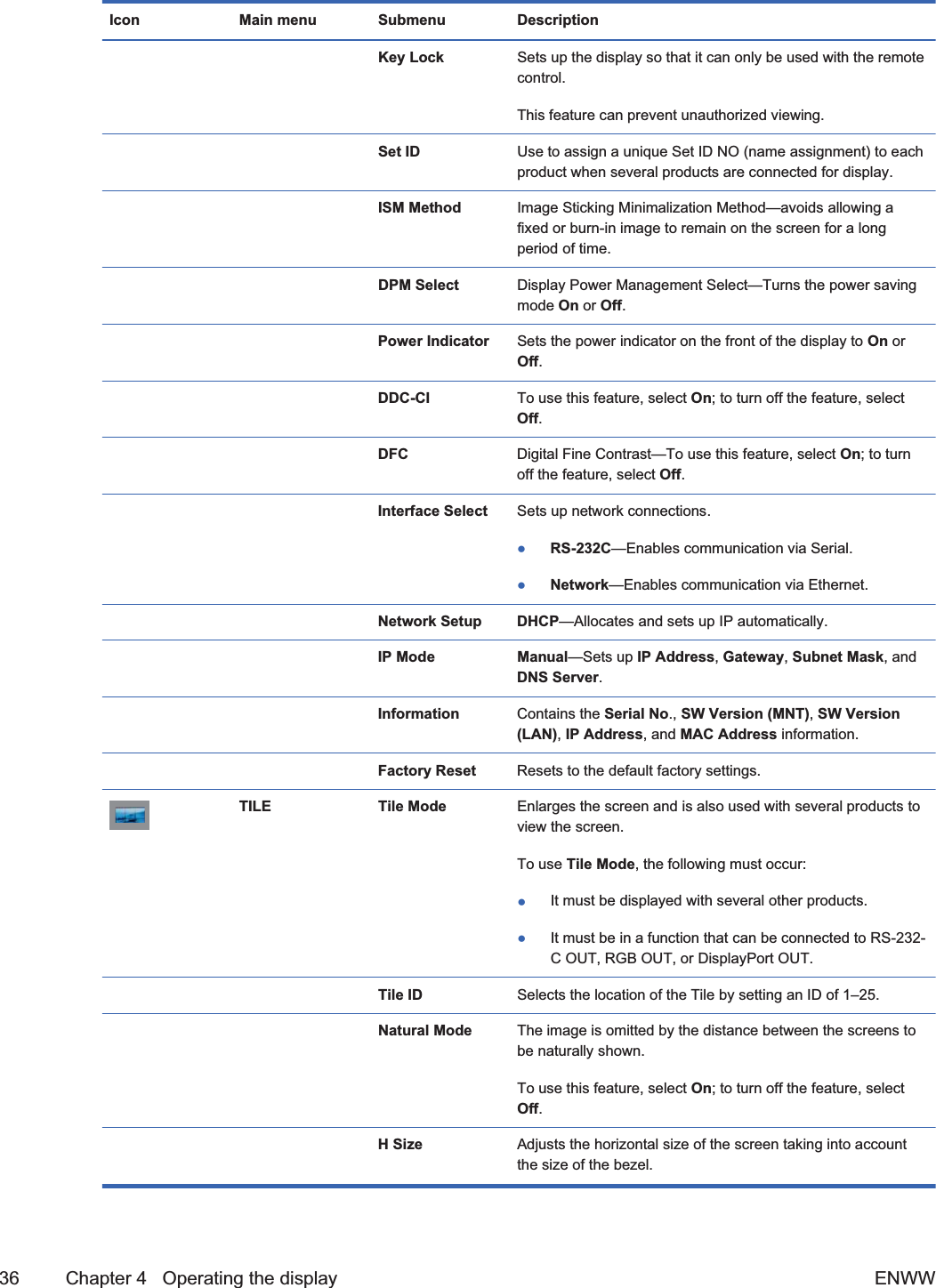
![Icon Main menu Submenu Description Expert 1 andExpert 2ControlSelect from the following settings:łDynamic Contrast—optimizes the contrast automaticallyaccording to the brightness of the reflection.łNoise Reduction—removes the noise up to the pointwhere it does not damage the original picture.łGamma—set your own gamma value. On the display,high gamma values display whitish images and lowgamma values display high contrast images.łBlack Level—adjusts the contrast and the brightness ofthe screen using the black level of the screen.łFilm Mode—adjusts the display, when watching a movie,to the best picture appearance.łColor Standard—adjusts color.łWhite Balance—adjusts the overall color of the screento the feeling you want.łColor Management System—adjusts by using testpatterns. This does not affect other colors but can beused to selectively adjust the 6 color areas (Red/ Green/Blue/Cyan/Magenta/Yellow). Color difference might notbe distinctive even when you make the adjustments for ageneral video. Picture Reset Returns the Picture Mode to the default factory settings. Screen Select from the following screen video settings:łResolution—to view a normal picture, match theresolution of RGB mode and selection of PC mode.(Function works in the following mode: RGB [PC] mode.)łAuto Config. (RGB PC input only)—automaticadjustment of the screen position, clock, and phase.(Function is available for analog signals only.)łPosition—moves the screen position.łSize—adjusts the size of the screen.łPhase—adjusts the focus of the display. This item allowsyou to remove any horizontal noise and clear or sharpenthe image of characters. (Function is available for analogsignals only.)łReset—returns Manual Config. to the default factorysettings.AUDIO Auto Volume Adjusts uneven sound volumes across all channels or signalsautomatically to the most appropriate level.To use this feature, select On; to turn off the feature, selectOff.34 Chapter 4 Operating the display ENWWDraft](https://usermanual.wiki/LG-Electronics-USA/HSTND-3101-G/User-Guide-1381578-Page-47.png)
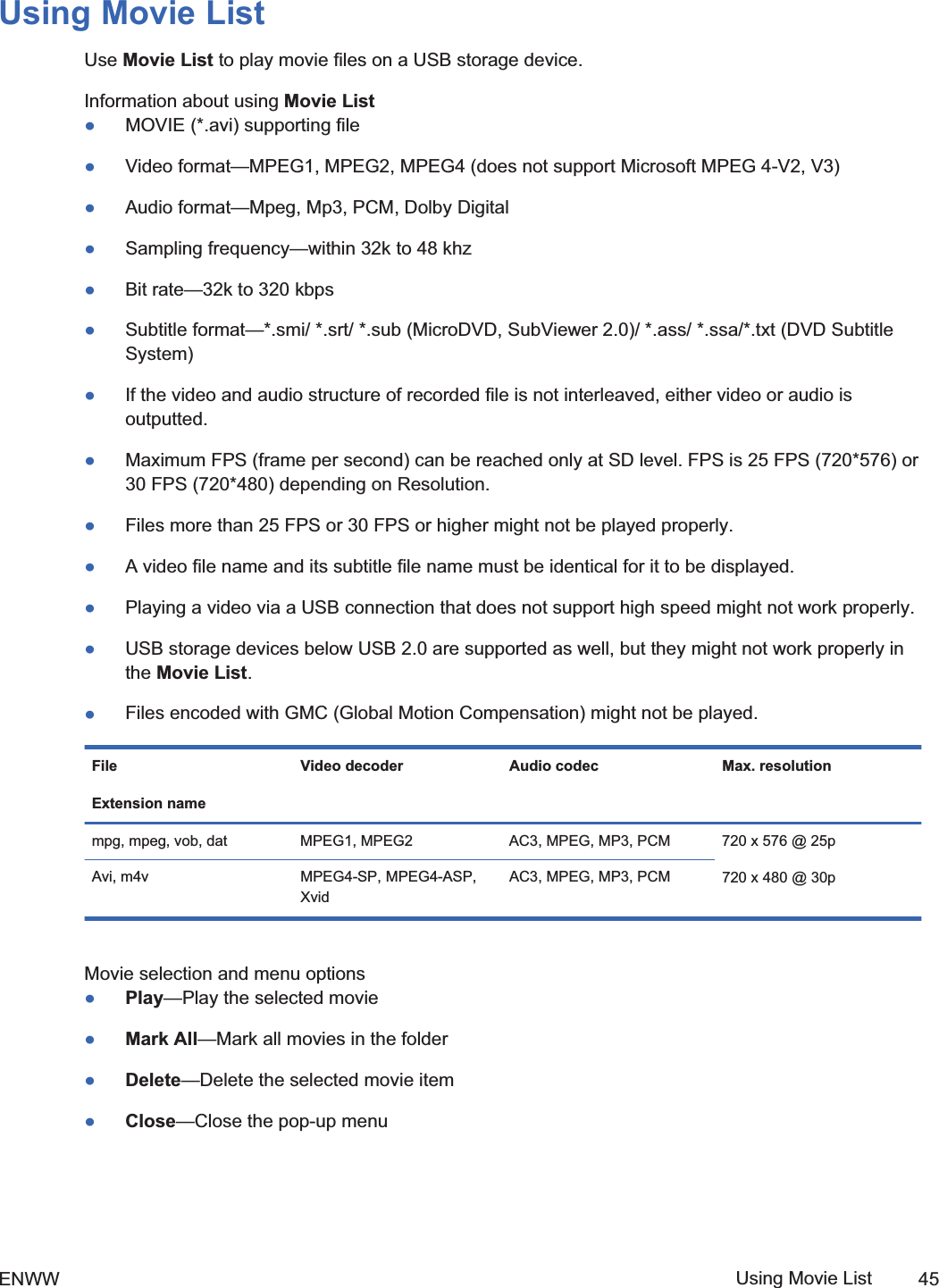
![5 Using the HP Media Sign Player[Author note:]The content for this section came from pages 34–37 of the 1st Draft of this UserGuide- per Brian Dodge.When you connect a USB storage device, the MY MEDIA menu appears with the options Photo List,Music List, or Movie List.NOTE: The MY MEDIA menu will not be displayed while the OSD is active, including the Menu,EPG, or Schedule list.CAUTION: Back up important files on the USB storage device before using with the display. Datamanagement is the responsibility of the user. Do not turn off the display or unplug the USB storagedevice when the connected device is working. When a USB storage device is suddenly separated orunplugged, the stored files or the device might be damaged.Information about using a USB storage devicełOnly a USB storage device is recognizable.łIf the USB storage device is connected through a USB hub, the device is not recognizable.łA USB storage device using an automatic recognition program might not be recognized.łA USB storage device which uses its own driver might not be recognized.łThe recognition speed of a USB storage device is specific to each device.łDo not connect a USB storage device which is artificially maneuvered on the media player/computer. The device might cause the display to malfunction or fail to play the files. Only use aUSB storage device which has standard music files or image files.łUse only a USB storage device which was formatted as a FAT16, FAT32, or NTFS file systemprovided with the Windows operating system. If a storage device is formatted using a differentutility program, which is not supported by Windows, it might not be recognized.łData in a USB storage device cannot be deleted or added in the NTFS file system.łConnect power to a USB storage device that requires an external power supply; otherwise, thedevice might not be recognized.łConnect a USB storage device with the cable provided by the USB manufacturer. When usingother cables or an excessively long cable, the device might not be recognized.łSome USB storage devices might not be supported or operate smoothly.łA maximum of 999 files and folders can be recognized.ENWW 412ndDraft](https://usermanual.wiki/LG-Electronics-USA/HSTND-3101-G/User-Guide-1381578-Page-54.png)

![Environment setupThe HP Network Sign Manager environment setup refers to connecting your signage display and theHP Network Sign Manager program to the network. There are three networking methods supportedfor the HP Network Sign Manager network setup:łLocal Area Network (LAN)łWide Area Network (WAN)łRS-232 Serial CommunicationConnecting a display via LAN or WANYou can connect the display to the network directly or indirectly via a router, hub, or switch. Connectthe network cable that is connected to the LAN or WAN to the Ethernet port on the signage display.Figure 6-1 Connecting a display via LAN or WAN[Author note:]Include this graphic from eZ-NetManager?Setting IP address to the network displayOnce the network cable is connected, set an IP address of the signage display to complete thenetwork connection.Follow the steps below to set an IP address of the display:1. Go to Menu on the display, and then select Option.2. In the Option dialog, select Interface Select, and then select Network.[Author note:]Need screen shot3. In the Option dialog, select Network Setup. Select how to assign an IP address under IPMode. You can assign an IP address either manually or using DHCP connection.łIf you choose to use the DHCP connection:a. Click Apply to assign an IP address automatically.b. Click Close to complete the IP address configuration.łIf you choose to assign manually:a. Configure an IP address, subnet mask, gateway, and DNS server address.b. Click Apply to save the IP address configuration.c. Click Close to complete the IP address configuration.4. Return to the Option dialog, select Information, and then select IP Address to check whetherthe IP address is properly assigned.ENWW Environment setup 51Draft](https://usermanual.wiki/LG-Electronics-USA/HSTND-3101-G/User-Guide-1381578-Page-64.png)
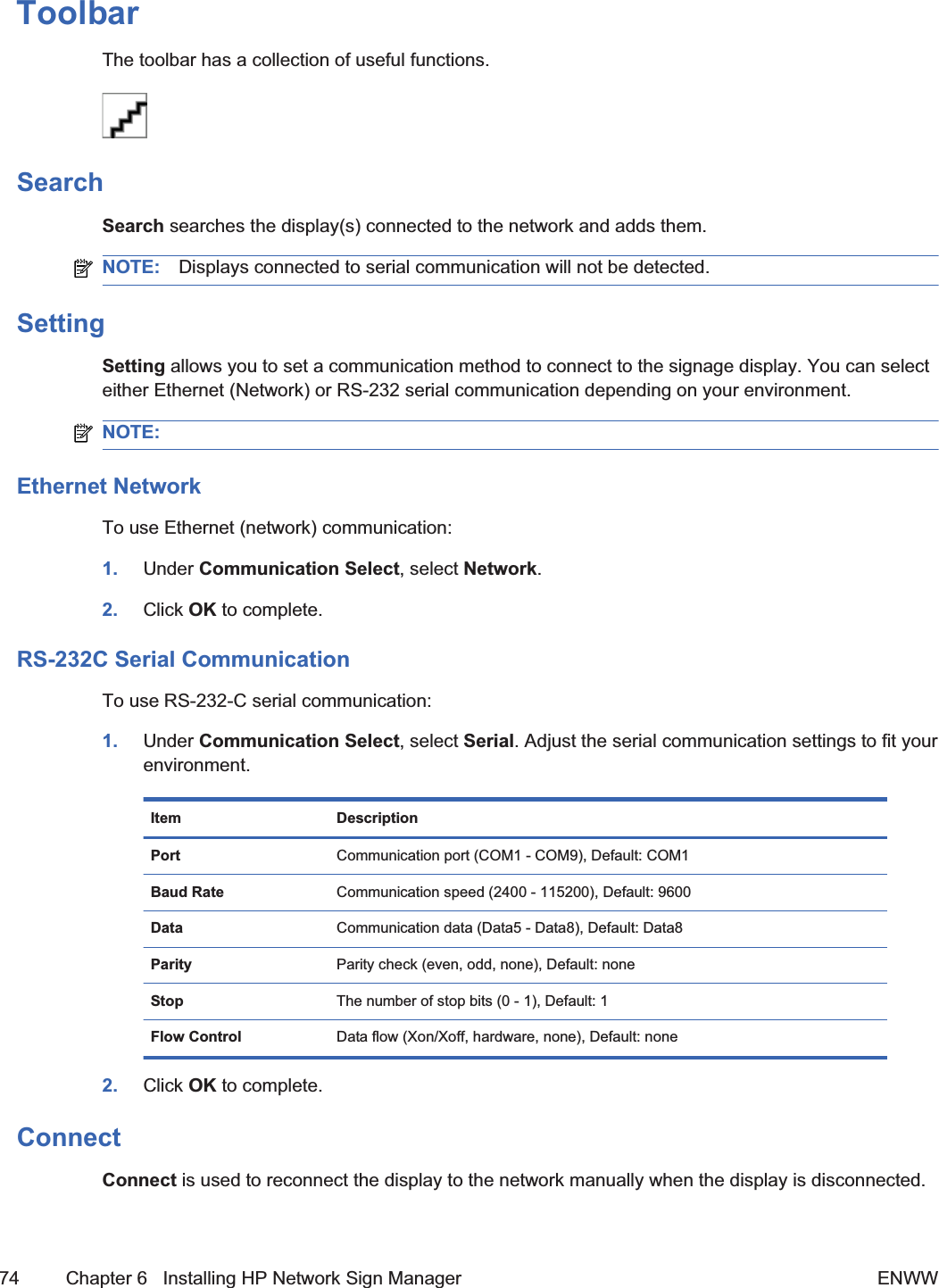
![Quick overviewHP Network Sign Manager is a network-based integrated solution management program supportingvarious features, including digital signage display control, image/video playback, and remote control.Home screen[Author note:]Need screen shot of Home screenA Toolbar Provides functions commonly used in HP Network Sign Manager such as networkeddisplay search/connection and communication configuration.B Monitor Register Window Adds and manages networked displays.C Control Tab Controls the settings of the selected display.D Control Panel Displays and configures settings for the selected function in the one of the controltabs.ToolbarTable 6-1 Provides functions commonly used in HP Network Sign Manager.[Author note:]Do you want asingle graphic with callouts or individual graphics in the left column of the table?Search is used to find display(s) that can be connected to the network and add them in the Add Monitorpane. The Search icon is enabled only when the communication configuration of HP Network SignManager is set to Ethernet.Setting is used to configure the communication method of HP Network Sign Manager. You can chooseeither Ethernet or serial connection.Connect is used to manually connect the selected display. The Connect icon is enabled only when thecommunication configuration of HP Network Sign Manager is set to Ethernet.Refresh is used to refresh the control panel information of HP Network Sign Manager.Message is used to display an instant message on the selected display.Alarm is used to send an alert message to the administrator if any problem occurs on the display or thenetwork.Security is used to change the user ID and password of HP Network Sign Manager.Help displays information about the HP Network Sign Manager program.54 Chapter 6 Installing HP Network Sign Manager ENWWDraft](https://usermanual.wiki/LG-Electronics-USA/HSTND-3101-G/User-Guide-1381578-Page-67.png)
![Control tabTable 6-2 The control tabs control the settings of the selected display.[Author note:]Do you want asingle graphic with callouts or individual graphics in the left column of the table?Information displays information on the hardware, network, status, and failures of the display.Control is used to control the power, input, volume, and OSD display settings of the display.A/V is used to change the sound and video settings of the display.Option is used to change the display of the display and settings of additional functions.Schedule is used to configure the timer settings to turn on and off the display.Tile is used to connect and set multiple displays.USB is used to set the playback schedule for the medial files stored in the USB device.Upgrade is used to upgrade the firmware of the display.ENWW Quick overview 552ndDraft](https://usermanual.wiki/LG-Electronics-USA/HSTND-3101-G/User-Guide-1381578-Page-68.png)
![Display and group managementHP Network Sign Manager supports to group and manage the monitors added in the Add Monitorpane.[Author note:]This sentence is confusing; what should it say?Making a groupThe following describes how to create a monitor group:1. Right-click the group in the Add Monitor pane. The shortcut menu appears.2. Click Make Group. The Make Group dialog appears.3. Enter a group name in the Make Group dialog, and then click Set.A new group is created under Group in the Add Monitor pane.Adding a display to groupYou can add monitors to the group you want and manage them by group.The following describes how to add monitors to a group:1. Right-click a monitor to group in the Add Monitor pane. The shortcut menu appears.2. Click Add to Group from the shortcut menu. The Group Selection dialog appears.3. Select a group to which the monitor is to be added under Group List.The monitor is now added to the selected group.NOTE: Alternatively, you can simply drag and drop a monitor to the group you want in the AddMonitor pane.Viewing group informationIf you select a group in the Add Monitor pane, you can see a summary of all monitors included in thegroup.AStatus Displays the network connection status of the monitors included in the selected group.BIP Address Displays the IP address of the monitors included in the selected group.CTag Displays the tag of the monitors included in the selected group. This field appears as "- - - -" ifthe monitor tag is not specified.DPower Displays the power on/off of the monitors included in the selected group.EInput Displays the input settings of the monitors included in the selected group.FSignal Displays the signal status of the monitors included in the selected group.60 Chapter 6 Installing HP Network Sign Manager ENWW2ndDraft](https://usermanual.wiki/LG-Electronics-USA/HSTND-3101-G/User-Guide-1381578-Page-73.png)
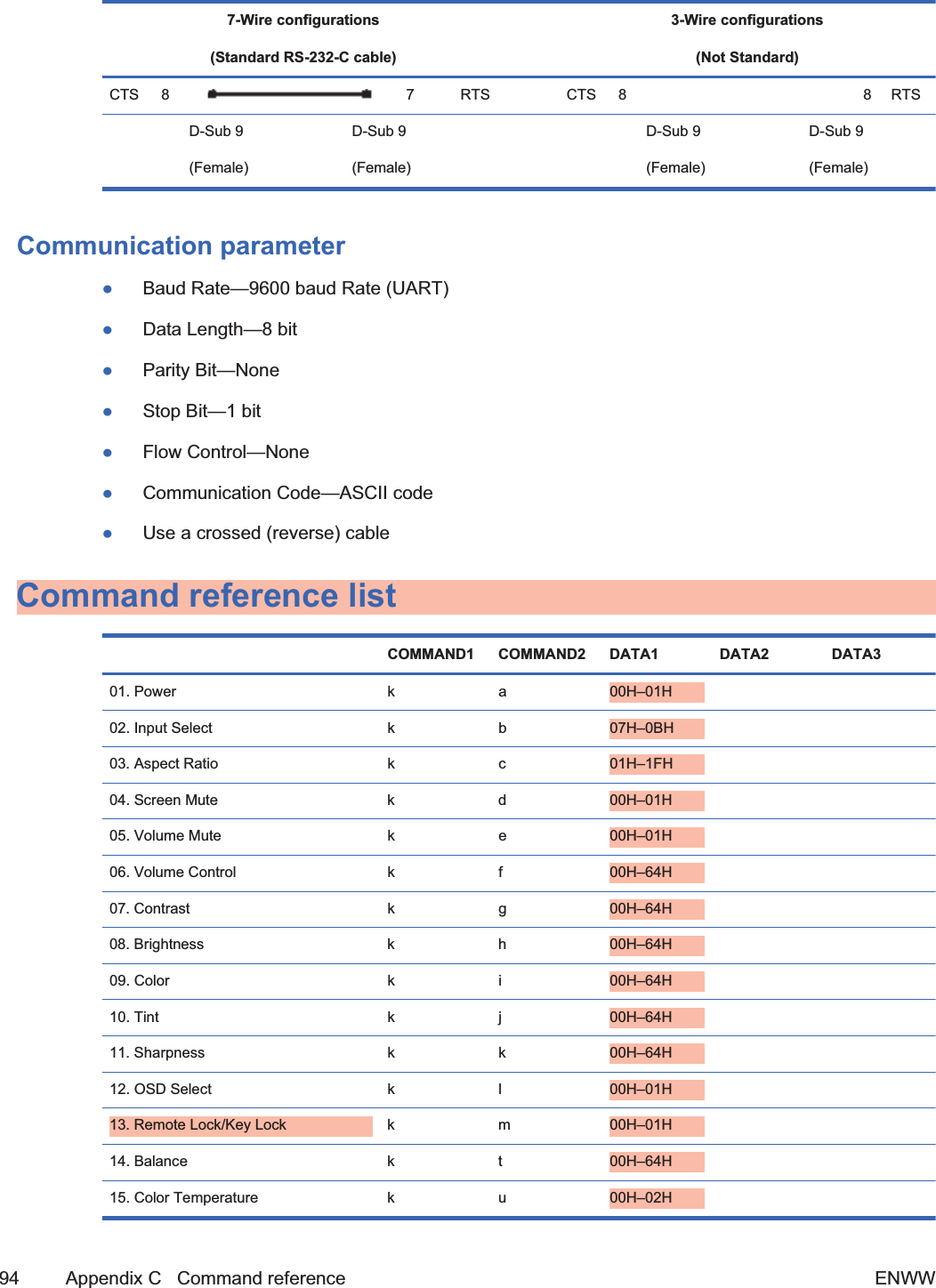
![COMMAND1 COMMAND2 DATA1 DATA2 DATA344. Reset f k 00H–02H 45. Power Saving f l 00H–03H 46. Power Indicator f o 00H–01H 47. Serial No. f y FFH 48. S/W Verison f z FFH 49. Input Select x b 60H–C0H Transmission/Receiving ProtocolTransmission[Command1][Command2][][Set ID][][Data][Cr][Command 1] First command (k, j, m, d, f, x)[Command 2] Second command (a to u)[Set ID] Set up the Set ID number of product. range : 01H to 63H. by setting'0', server can control all products.In case of operating with more than 2 sets using set ID as '0' at thesame time, it should not be checked the ack message. Because allsets will send the ack message, so it's impossible the check thewhole ack messages.[Data] To transmit command data.Transmit 'FF' data to read status of command.[Cr] Carriage ReturnASCII code '0 x 0 D'[] ASCII code Space (0 x 20)OK Acknowledgement[Command2][][Set ID][][OK][Data][x]*The Product transmits ACK (acknowledgement) based on this format when receiving normal data. Atthis time, if the data is in data read mode, it indicates present status data. If the data is in data writemode, it returns the data of the media player/computer.Error Acknowledgement96 Appendix C Command reference ENWW2ndDraft](https://usermanual.wiki/LG-Electronics-USA/HSTND-3101-G/User-Guide-1381578-Page-109.png)
![[Command2][][Set ID][][NG][Data][x]*If there is error, it returns NG01. Power (Command : a)To control Power On/Off of the Set.Transmission[k][a][][Set ID][][Data][Cr][Data] 0 : Power Off1 : Power OnAcknowledgement[a][][Set ID][][OK][Data][x]To show the status of Power On/Off.Transmission[k][a][][Set ID][][FF][Cr]Acknowledgement[a][][Set ID][][OK][Data][x][Data] 0 : Power Off1 : Power On02. Input Select (Command : b) (Main Picture Input)To select input source for the Set.You can also select an input source using the INPUT button on the remote control.TransmissionENWW Transmission/Receiving Protocol 972ndDraft](https://usermanual.wiki/LG-Electronics-USA/HSTND-3101-G/User-Guide-1381578-Page-110.png)
![[k][b][][Set ID][][Data][Cr][Data] 7 : RGB (PC)8 : HDMI (DTV)9 : HDMI (PC)A: Display port (DTV)B: Display port (PC)Acknowledgement[b][][Set ID][][OK][Data][x][Data] 7 : RGB (PC)8 : HDMI (DTV)9 : HDMI (PC)A: Display port (DTV)B: Display port (PC)03. Aspect Ratio (Command : c) (Main picture format)To adjust the screen format.You can also adjust the screen format using the ARC (Aspect Ratio Control) button on remote controlor in the Screen menu.Transmission[k][c][][Set ID][][Data][Cr]98 Appendix C Command reference ENWWDraft](https://usermanual.wiki/LG-Electronics-USA/HSTND-3101-G/User-Guide-1381578-Page-111.png)
![[Data] 1 : Normal Screen (4:3)2 : Wide Screen (16:9)4 : Zoom (HDMI-PC, Display Port-PC)6 : Original7 : 14:9 (HDMI-PC, Display Port-PC)9 : Just Scan (HD-DTV)*When the RGB, HDMI/DVI-PC, DisplayPort-PCmode (1:1)10 to 1F : Cinema Zoom 1 to 16 (HD-DTV)Acknowledgement[c][][Set ID][][OK][Data][x]04. Screen Mute (Command : d)To select screen mute on/off.Transmission[k][d][][Set ID][][Data][Cr][Data] 0 : Screen mute off (Picture on)1 : Screen mute on (Picture off)Acknowledgement[d][][Set ID][][OK][Data][x]05. Volume Mute (Command : e)To control On/Off of the Volume Mute.Transmission[k][e][][Set ID][][Data][Cr]ENWW Transmission/Receiving Protocol 992ndDraft](https://usermanual.wiki/LG-Electronics-USA/HSTND-3101-G/User-Guide-1381578-Page-112.png)
![[Data] 0 : Volume Mute On (Volume Off)1 : Volume Mute Off (Volume On)Acknowledgement[e][][Set ID][][OK][Data][x][Data] 0 : Volume Mute On (Volume Off)1 : Volume Mute Off (Volume On)06. Volume Control (Command : f)To adjust Volume.Transmission[k][f][][Set ID][][Data][Cr][Data] Min : 00H to Max : 64H(Hexadecimal code)Acknowledgement[f][][Set ID][][OK][Data][x][Data] Min : 00H to Max : 64H100 Appendix C Command reference ENWW2ndDraft](https://usermanual.wiki/LG-Electronics-USA/HSTND-3101-G/User-Guide-1381578-Page-113.png)
![Real data mapping 0 : Step 0:A : Step 10:F : Step 1510 : Step 16:64 : Step 10007. Contrast (Command : g)To adjust screen contrast. You can also adjust the contrast in the Picture menu.Transmission[k][g][][Set ID][][Data][Cr][Data] Min : 00H to Max : 64HAcknowledgement[g][][Set ID][][OK][Data][x]Real data mapping 0 : Step 0:A : Step 10:F : Step 1510 : Step 16:64 : Step 10008. Brightness (Command : h)To adjust screen brightness. You can also adjust the brightness in the Picture menu.ENWW Transmission/Receiving Protocol 1012ndDraft](https://usermanual.wiki/LG-Electronics-USA/HSTND-3101-G/User-Guide-1381578-Page-114.png)
![Transmission[k][h][][Set ID][][Data][Cr][Data] Min : 00H to Max : 64HRefer to “Real data mapping” as shown below.Acknowledgement[h][][Set ID][][OK][Data][x]Real data mapping 0 : Step 0:A : Step 10:F : Step 1510 : Step 16:64 : Step 10009. Color (Command : i) (Video Timing only)To adjust the screen color. You can also adjust the color in the Picture menu.Transmission[k][i][][Set ID][][Data][Cr][Data] Min : 00H to Max : 64H(Hexadecimal code)102 Appendix C Command reference ENWW2ndDraft](https://usermanual.wiki/LG-Electronics-USA/HSTND-3101-G/User-Guide-1381578-Page-115.png)
![Real data mapping 0 : Step 0:A : Step 10:F : Step 1510 : Step 16:64 : Step 100Acknowledgement[i][][Set ID][][OK][Data][x][Data] Min : 00H to Max : 64H(Hexadecimal code)10. Tint (Command : j) (Video Timing only)To adjust the screen tint. You can also adjust the tint in the Picture menu.Transmission[k][j][][Set ID][][Data][Cr][Data] Red: 00H to Green: 64H(Hexadecimal code)ENWW Transmission/Receiving Protocol 1032ndDraft](https://usermanual.wiki/LG-Electronics-USA/HSTND-3101-G/User-Guide-1381578-Page-116.png)
![Real data mapping 0 : Step 0:A : Step 10:F : Step 1510 : Step 16:64 : Step 100Acknowledgement[j][][Set ID][][OK][Data][x][Data] Red: 00H to Green: 64HTint real data mapping 0 : Step 0 to Red:64 : Step 100 to Green11. Sharpness (Command : k) (Video Timing only)To adjust the screen Sharpness. You can also adjust the sharpness in the Picture menu.Transmission[k][k][][Set ID][][Data][Cr][Data] Min : 00H to Max : 64H(Hexadecimal code)104 Appendix C Command reference ENWW2ndDraft](https://usermanual.wiki/LG-Electronics-USA/HSTND-3101-G/User-Guide-1381578-Page-117.png)
![Real data mapping 0 : Step 0:A : Step 10:F : Step 1510 : Step 16:64 : Step 100Acknowledgement[k][][Set ID][][OK][Data][x][Data] Min : 00H to Max : 64H12. OSD Select (Command : l)To control OSD on/off to the set.Transmission[k][l][][Set ID][][Data][Cr][Data] 0 : OSD Off1 : OSD OnAcknowledgement[l][][Set ID][][OK][Data][x][Data] 0 : OSD Off1 : OSD OnENWW Transmission/Receiving Protocol 1052ndDraft](https://usermanual.wiki/LG-Electronics-USA/HSTND-3101-G/User-Guide-1381578-Page-118.png)
![13. Remote Lock /Key Lock (Command : m)To control Remote Lock on/off to the set.This function, when controlling RS-232C, locks the remote control and the local keys.Transmission[k][m][][Set ID][][Data][Cr][Data] 0 : Off1 : OnAcknowledgement[m][][Set ID][][OK][Data][x][Data] 0 : Off1 : On14. Balance (Command : t)To adjust the sound balance.Transmission[k][t][][Set ID][][Data][Cr][Data] Min : 00H to Max : 64H(Hexadecimal code)00H : Step L5064H : Step R50Acknowledgement[t][][Set ID][][OK][Data][x]106 Appendix C Command reference ENWW2ndDraft](https://usermanual.wiki/LG-Electronics-USA/HSTND-3101-G/User-Guide-1381578-Page-119.png)
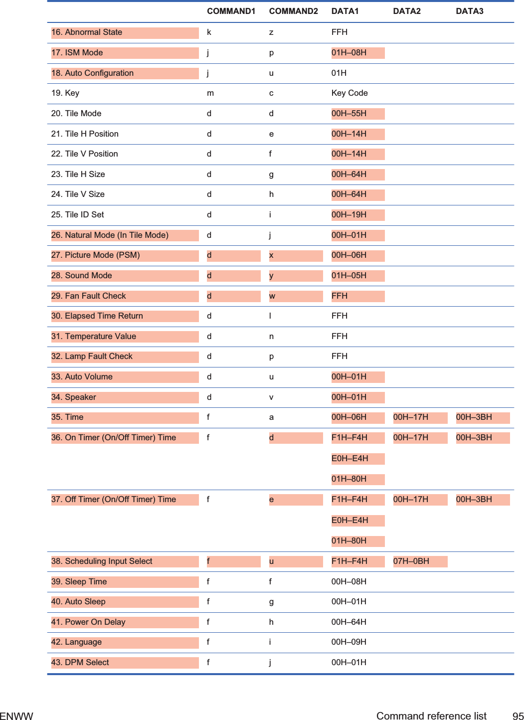
![[Data] Min : 00H to Max : 64H00H : Step 0 to L5064H : Step 100 to R50Balance : L50 to R5015. Color Temperature (Command : u)To adjust the screen color temperature.Transmission[k][u][][Set ID][][Data][Cr][Data] 0 : Medium1 : Cool2 : WarmAcknowledgement[u][][Set ID][][OK][Data][x][Data] 0 : Medium1 : Cool2 : Warm16. Abnormal state (Command : z)Abnormal State : Used to Read the power off status when Stand-by mode.Transmission[k][z][][Set ID][][Data][Cr][Data] FF : ReadAcknowledgementENWW Transmission/Receiving Protocol 1072ndDraft](https://usermanual.wiki/LG-Electronics-USA/HSTND-3101-G/User-Guide-1381578-Page-120.png)
![[z][][Set ID][][OK][Data][x][Data] 0 : Normal (Power on and signal exist)1 : No signal (Power on)2 : Turn the display off by remote control3 : Turn the display off by sleep time function4 : Turn the display off by RS-232-C function8 : Turn the display off by off time function9 : Turn the display off by auto off function17. ISM mode (Command : j p)Used to select the afterimage preventing function.Transmission[j][p][][Set ID][][Data][Cr][Data] 1H : Inversion2H : Orbiter4H : White Wash8H : NormalAcknowledgement[p][][Set ID][][OK][Data][x]18. Auto Configure (Command : j u)To adjust picture position and minimize image shaking automatically. It works only in RGB (PC)mode.Transmission[j][u][][Set ID][][Data][Cr]108 Appendix C Command reference ENWW2ndDraft](https://usermanual.wiki/LG-Electronics-USA/HSTND-3101-G/User-Guide-1381578-Page-121.png)
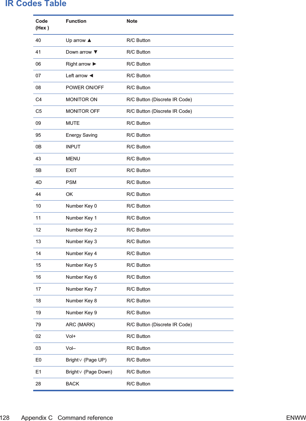
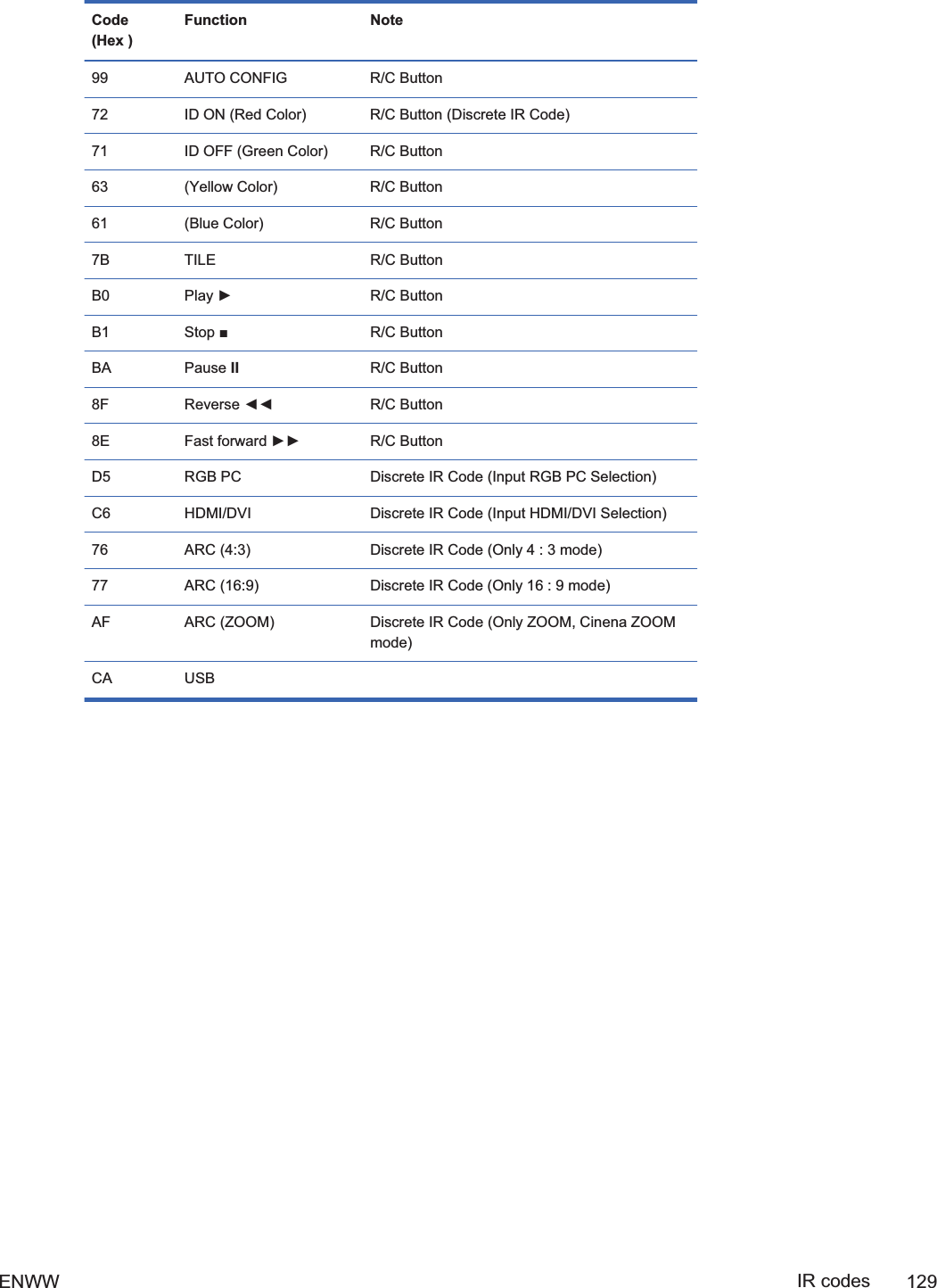
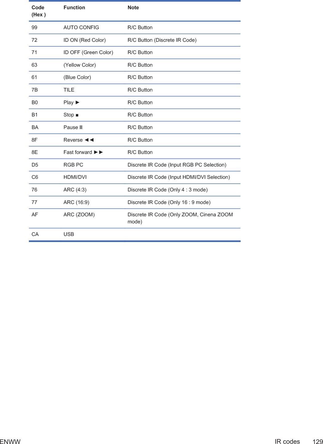
![[Data] 1 : To setAcknowledgement[u][][Set ID][][OK][Data][x]19. Key (Command : m c)To send IR remote key code.Transmission[m][c][][Set ID][][Data][Cr]Data Key code : Refer to the IR Codes Table on page 128 section.Acknowledgement[c][][Set ID][][OK][Data][x]20. Tile Mode (Command : d d)Change a Tile Mode.Transmission[d][d][][Set ID][][Data][x][Data] Description00 or 11 Tile mode is off.12 1 x 2 mode (column x row)13 1 x 3 mode14 1 x 4 mode... ...55 5 x 5 mode*The data cannot be set to 0X or X0 except 00.AcknowledgementENWW Transmission/Receiving Protocol 109Draft](https://usermanual.wiki/LG-Electronics-USA/HSTND-3101-G/User-Guide-1381578-Page-122.png)
![[d][][00][][OK/NG][Data][x]21. Tile H Position (Command : d e)To set the Horizontal position.Transmission[d][e][][Set ID][][Data][x][Data] Min : 00H to Max : 14H00H : Step -10 (Left)14H : Step 10 (Right)Acknowledgement[e][][Set ID][][OK/NG][Data][x]22. Tile V Position (Command : d f)To set the Vertical position.Transmission[d][f][][Set ID][][Data][x][Data] Min : 00H to Max : 14H00H : Step -10 (Left)14H : Step 10 (Right)Acknowledgement[f][][Set ID][][OK/NG][Data][x]23. Tile H Size (Command : d g)To set the Horizontal size.110 Appendix C Command reference ENWW2ndDraft](https://usermanual.wiki/LG-Electronics-USA/HSTND-3101-G/User-Guide-1381578-Page-123.png)
![Transmission[d][g][][Set ID][][Data][x][Data] Min : 00H to Max : 64HReal data mapping 0 : Step 0:A : Step 10:F : Step 1510 : Step 16:64 : Step 100Acknowledgement[g][][Set ID][][OK/NG][Data][x]24. Tile V Size (Command : d h)To set the Vertical size.Transmission[d][h][][Set ID][][Data][x][Data] Min : 00H to Max : 64HENWW Transmission/Receiving Protocol 1112ndDraft](https://usermanual.wiki/LG-Electronics-USA/HSTND-3101-G/User-Guide-1381578-Page-124.png)
![Real data mapping 0 : Step 0:A : Step 10:F : Step 1510 : Step 16:64 : Step 100Acknowledgement[h][][Set ID][][OK/NG][Data][x]25. Tile ID Set (Command : d i)To assign the Tile ID for Tiling function.Transmission[d][i][][Set ID][][Data][x][Data] Min : 00H to Max : 19H(Hexadecimal code)Acknowledgement[i][][Set ID][][OK/NG][Data][x]26. Natural Mode (In Tile Mode) (Command : d j)To assign the Title Natural mode for Tiling function.Transmission[d][j][][Set ID][][Data][x]112 Appendix C Command reference ENWW2ndDraft](https://usermanual.wiki/LG-Electronics-USA/HSTND-3101-G/User-Guide-1381578-Page-125.png)
![[Data] 0 : Natural Off1 : Natural Onff : Read StatusAcknowledgement[j][][Set ID][][OK/NG][Data][x]27. Picture Mode (Command : d x)To adjust the picture mode.Transmission[d][x][][Set ID][][Data][x]Data StructureData (Hex) MODE00 Vivid01 Standard02 Cinema03 Sport04 Game05 Expert 106 Expert 2Acknowledgement[x][][Set ID][][OK/NG][Data][x]28. Sound Mode (Command : d y )To adjust the Sound mode.Transmission[d][y][][Set ID][][Data][X]ENWW Transmission/Receiving Protocol 1132ndDraft](https://usermanual.wiki/LG-Electronics-USA/HSTND-3101-G/User-Guide-1381578-Page-126.png)
![Data StructureData (Hex) MODE01 Standard02 Music03 Cinema04 Sport05 GameAcknowledgement[y][][Set ID][][OK/NG][Data][x]29. Fan Fault check (Command : d w )To check the Fan fault of the TV.Transmission[d][w][][Set ID][][Data][x][Data] Data is always FF (in Hex)Data ff: Read StatusAcknowledgement[w][][Set ID][][OK/NG][Data][x][Data] * Data is the status value of the Fan fault.0: Fan fault1: Fan OK2: N/A (Not Avaliable)30. Elapsed time return (Command : d l)To read the elapsed time.114 Appendix C Command reference ENWW2ndDraft](https://usermanual.wiki/LG-Electronics-USA/HSTND-3101-G/User-Guide-1381578-Page-127.png)
![Transmission[d][l][][Set ID][][Data][x][Data] Data is always FF (in Hex)Acknowledgement[l][][Set ID][][OK/NG][Data][x][Data] The data means used hours.(Hexadecimal code)31. Temperature value (Command : d n)To read the inside temperature value.Transmission[d][n][][Set ID][][Data][x][Data] Data is always FF (in Hex)Acknowledgement[n][][Set ID][][OK/NG][Data][x][Data] The data is 1 byte long in Hexadecimal.32. Lamp fault Check (Command : d p)To check lamp fault.Transmission[d][p][][Set ID][][Data][x]ENWW Transmission/Receiving Protocol 1152ndDraft](https://usermanual.wiki/LG-Electronics-USA/HSTND-3101-G/User-Guide-1381578-Page-128.png)
![[Data] Data is always FF (in Hex)Acknowledgement[p][][Set ID][][OK/NG][Data][x][Data] 0 : Lamp Fault1 : Lamp OK2 : N/A(DPM/Power Off)33. Auto volume (Command : d u)Automatically adjust the volume level.Transmission[d][u][][Set ID][][Data][x][Data] 0 : Off1 : OnAcknowledgement[u][][Set ID][][OK/NG][Data][x]34. Speaker (Command : d v)Turn the speaker on or off.Transmission[d][v][][Set ID][][Data][x][Data] 0 : Off1 : OnAcknowledgement116 Appendix C Command reference ENWW2ndDraft](https://usermanual.wiki/LG-Electronics-USA/HSTND-3101-G/User-Guide-1381578-Page-129.png)
![[v][][Set ID][][OK/NG][Data][x]35. Time (Command : f a)Set the current time.Transmission[f][a][][Set ID][][Data1][][Data2][][Data3][Cr][Data1] 0 : Monday1 : Tuesday2 : Wednesday3 : Thursday4 : Friday5 : Saturday6 : Sunday[Data2] 0H to 17H (Hours)[Data3] 00H to 3BH (Minutes)Acknowledgement[a][][Set ID][][OK/NG][Data1][Data2][Data3][x]*When reading data, FFH is inputted for [Data1], [Data2] and [Data3]. In other cases, all are treatedas NG.36. On Timer (On/Off Timer) Time (Command : f d)Set On Timer.Transmission[f][d][][Set ID][][Data1][][Data2][][Data3][Cr]ENWW Transmission/Receiving Protocol 1172ndDraft](https://usermanual.wiki/LG-Electronics-USA/HSTND-3101-G/User-Guide-1381578-Page-130.png)
![1. 2. 3.[Data1] f1h to f4h (read one index) e0htoe4h (delete one index),e0h (delete all indexes)01h to 80h (write) (Day of Week)f1: read 1st index of On TimeListe0: delete all indexes of On TimeListbit0 (01h) : Mondayf2: read 2nd index of On TimeListe1: delete 1st index of On TimeListbit1 (02h) : Tuesdayf3: read 3rd index of On TimeListe2: delete 2nd index of On TimeListbit2 (04h) : Wednesdayf4: read 4th index of On TimeListe3: delete 3rd index of On TimeListbit3 (08h) : Thursdaybit4 (10h) : Fridaye4: delete 4th index of On TimeListbit5 (20h) : Saturdaybit6 (40h) : Sundaybit7 (80h) : Everyday(1fh) : Monday to Friday(3fh) : Monday to Saturday(60h) : Saturday to Sunday[Data2] 00h to 17h, ffh (Hours)[Data3] 00h to 3bh, ffh (Minutes)*When you read/delete the current on time list, all of [Data2][Data3] have to be0xff.ex1: fd 01 f1 ff ff - when you read 1st index of On Time Listex2: fd 01 e1 ff ff - when you delete 1st index of On Time Listex3: fd 01 3f 02 03 - when you write one On Time Data, "Monday to Saturday,02:03"Acknowledgement[d][][Set ID][][OK][Data1][Data2][Data3][x]37. Off Timer (On/Off Timer) Time (Command : f e)Set Off Timer.118 Appendix C Command reference ENWW2ndDraft](https://usermanual.wiki/LG-Electronics-USA/HSTND-3101-G/User-Guide-1381578-Page-131.png)
![Transmission[f][e][][Set ID][][Data1][][Data2][][Data3][Cr] 1. 2. 3.[Data1] f1h to f4h (read one index) e0htoe4h(delete one index), e0h(delete all indexes)01h to 80h (write) (Day of Week)f1: read 1st index of On TimeListe0: delete all indexes of On TimeListbit0 (01h) : Mondayf2: read 2nd index of On TimeListe1: delete 1st index of On TimeListbit1 (02h) : Tuesdayf3: read 3rd index of On TimeListe2: delete 2nd index of On TimeListbit2 (04h) : Wednesdayf4: read 4th index of On TimeListe3: delete 3rd index of On TimeListbit3 (08h) : Thursdaybit4 (10h) : Fridaye4: delete 4th index of On TimeListbit5 (20h) : Saturdaybit6 (40h) : Sundaybit7 (80h) : Everyday(1fh) : Monday to Friday(3fh) : Monday to Saturday(60h) : Saturday to Sunday[Data2] 00h to 17h, ffh (Hours)[Data3] 00h to 3bh, ffh (Minutes)*When you read/delete the current on time list, all of [Data2][Data3] have to be0xff.ex1: fd 01 f1 ff ff - when you read 1st index of On Time Listex2: fd 01 e1 ff ff - when you delete 1st index of On Time Listex3: fd 01 3f 02 03 - when you write one On Time Data, "Monday to Saturday,02:03"AcknowledgementENWW Transmission/Receiving Protocol 1192ndDraft](https://usermanual.wiki/LG-Electronics-USA/HSTND-3101-G/User-Guide-1381578-Page-132.png)
![[e][][Set ID][][OK][Data1][Data2][Data3][x]38. Scheduling Input select (Command : f u) (Main Picture Input)To select input source for TV depending on day.Transmission[f][u][][Set ID][][Data1][][Data2][Cr] 1.[Data1] f1h to f4h(write/read one index)f1: read 1st index of On Time Inputf2: read 2nd index of On Time Inputf3: read 3rd index of On Time Inputf4: read 4th index of On Time Input Data (Hex) INPUT[Data2] 07 RGB-PC08 HDMI/DVI — HD-DVD09 HDMI/DVI—PCA Display port (-HD-DVI)B Display port PC)*When you read/delete the current On Time Input, [Data2] needs to be 0xff.ex1: fu 01 f1 ff - when you read 1st index of On Time Inputex2: fu 01 f3 02 - when you write one On Time Input Data in to 3rd index, "AV"Acknowledgement[u][][Set ID][][OK][Data1][Data2][x]120 Appendix C Command reference ENWW2ndDraft](https://usermanual.wiki/LG-Electronics-USA/HSTND-3101-G/User-Guide-1381578-Page-133.png)
![39. Sleep Time (Command : f f)Set Sleep Time.Transmission[f][f][][Set ID][][Data][Cr][Data] 0 : Off1 : 102 : 203 : 304 : 605 : 906 : 1207 : 1808 : 240Acknowledgement[f][][Set ID][][OK/NG][Data][x]40. Auto Sleep (Command : f g)Set Auto Sleep.Transmission[f][g][][Set ID][][Data][Cr][Data] 0 : Off1 : OnAcknowledgement[g][][Set ID][][OK/NG][Data][x]ENWW Transmission/Receiving Protocol 1212ndDraft](https://usermanual.wiki/LG-Electronics-USA/HSTND-3101-G/User-Guide-1381578-Page-134.png)
![41. Power On Delay (Command : f h)Set the schedule delay when the power is turned on (Unit: second).Transmission[f][h][][Set ID][][Data][Cr][Data] 00H to 64H (Data value)Real data mapping 0 : Step 0:A : Step 10:F : Step 1510 : Step 16:64 : Step 100Acknowledgement[h][][Set ID][][OK/NG][Data][x]42. Language (Command : f i)Set the OSD language.Transmission[f][i][][Set ID][][Data][Cr]122 Appendix C Command reference ENWW2ndDraft](https://usermanual.wiki/LG-Electronics-USA/HSTND-3101-G/User-Guide-1381578-Page-135.png)
![[Data] 0 : English1 : French2 : German3 : Spanish4 : Italian5 : Portuguese6 : Chinese7 : Japanese8 : Korean9 : RussianAcknowledgement[i][][Set ID][][OK/NG][Data][x]43. DPM Select (Command : f j)Set the DPM (Display Power Management) function.Transmission[f][j][][Set ID][][Data][Cr][Data] 0 : Off1 : OnAcknowledgement[j][][Set ID][][OK/NG][Data][x]44. Reset (Command : f k)Execute the Picture, Screen and Factory Reset functions.Transmission[f][k][][Set ID][][Data][Cr]ENWW Transmission/Receiving Protocol 123Draft](https://usermanual.wiki/LG-Electronics-USA/HSTND-3101-G/User-Guide-1381578-Page-136.png)
![[Data] 0 : Picture Reset1 : Screen Reset2 : Factory ResetAcknowledgement[k][][Set ID][][OK/NG][Data][x]45. Power saving(Command : f I)To set the Power saving mode.Transmission[f][I][][Set ID][][Data][Cr][Data] 0 : Off1: (static level 1)2: (static level 2)3: (static level 3)Acknowledgement[I][][Set ID][][OK/NG][Data][x]46. Power Indicator (Command : f o)To set the LED for Power IndicatorTransmission[f][o][][Set ID][][Data][Cr][Data] 0 : Off1 : OnAcknowledgement124 Appendix C Command reference ENWWDraft](https://usermanual.wiki/LG-Electronics-USA/HSTND-3101-G/User-Guide-1381578-Page-137.png)
![[o][][Set ID][][OK/NG][Data][x]47. Serial no. Check (Command : f y)To read the serial numbersTransmission[f][y][][Set ID][][Data][Cr][Data] Data FF (to read the serial numbers)Acknowledgement[y][][Set ID][][OK/NG][Data1]to[Data13][x][Data] The data format is ASCII Code.48. S/W Version (Command : f z)Check the software version.Transmission[f][z][][Set ID][][Data][Cr][Data] FFH : ReadAcknowledgement[z][][Set ID][][OK/NG][Data][x]49. Input Select (Command : x b)To select input source for the display.TransmissionENWW Transmission/Receiving Protocol 1252ndDraft](https://usermanual.wiki/LG-Electronics-USA/HSTND-3101-G/User-Guide-1381578-Page-138.png)
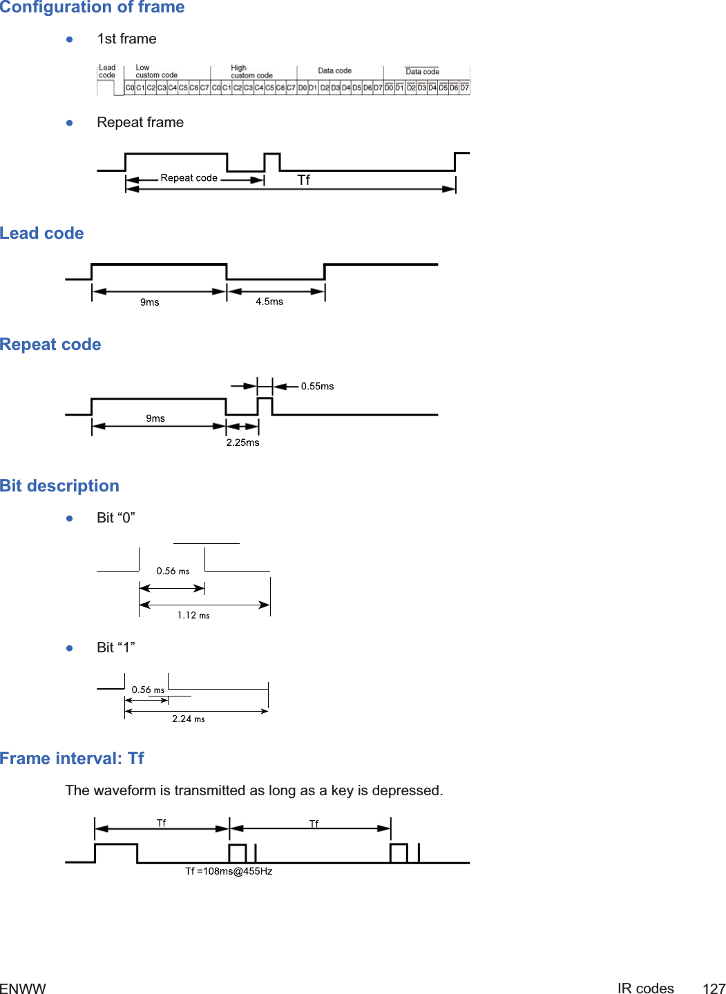
![[x][b][][Set ID][][Data][Cr][Data] 60H : RGB (PC)90H : HDMI/DVI (DTV)A0H : HDMI/DVI (PC)B0H: Display port(HD-DVD)C0H: Display port(PC)Acknowledgement[b][][Set ID][][OK][Data][x][Data] 60H : RGB (PC)90H : HDMI/DVI (DTV)A0H : HDMI/DVI (PC)B0H: Display port(HD-DVD)C0H: Display port(PC)IR codesUse this method to connect your wired remote control port on the display.Remote Control IR CodeOutput waveformłSingle pulse, modulated with 37.917kHz signal at 455kHzłCarrier FrequencyŃFCAR = 1/Tc=fosc/12ŃDuty Ratio = T1/Tc = 1/3126 Appendix C Command reference ENWW2ndDraft](https://usermanual.wiki/LG-Electronics-USA/HSTND-3101-G/User-Guide-1381578-Page-139.png)