LG Electronics USA HSTND-3101-G Digital Signage Display User Manual G User s manual
LG Electronics USA Digital Signage Display G User s manual
user manual

G
Order Number : GETEC-C1-10-209 FCC Part 15 subpart B
Test Report Number : GETEC-E3-10-112 Page 1 / 1
EUT Type: Digital Signage Display
FCC ID.: BEJHSTND-3101-G
APPENDIX G
: USER’S MANUAL

HP LD4201, LD4210 and LD4710
Digital Signage Displays
User Guide
2
n
d
D
r
aft

© 2010 Hewlett-Packard Development
Company, L.P. The information contained
herein is subject to change without notice.
Microsoft®, Windows®, Windows® XP, and
Windows Vista® are either trademarks or
registered trademarks of Microsoft
Corporation in the United States and/or
other countries.
The only warranties for HP products and
services are set forth in the express
warranty statements accompanying such
products and services. Nothing herein
should be construed as constituting an
additional warranty. HP shall not be liable
for technical or editorial errors or omissions
contained herein.
This document contains proprietary
information that is protected by copyright.
No part of this document may be
photocopied, reproduced, or translated to
another language without the prior written
consent of Hewlett-Packard Company.
First Edition (November 2010)
Document Part Number: 626995–001
2
n
d
D
r
aft

About this guide
This guide provides information on setting up the display, installing drivers, using the On-Screen
Display menu, troubleshooting, and technical specifications.
WARNING! Text set off in this manner indicates that failure to follow directions could result in bodily
harm or loss of life.
CAUTION: Text set off in this manner indicates that failure to follow directions could result in
damage to equipment or loss of information.
NOTE: Text set off in this manner provides important supplemental information.
ENWW iii
2
n
d
D
r
aft
iv About this guide ENWW
2
n
d
D
r
af
t

Table of contents
1 Product features ............................................................................................................................................. 1
HP Digital Signage models ................................................................................................................... 1
Accessories .......................................................................................................................................... 2
Optional accessories ............................................................................................................................ 2
2 Safety and maintenance guidelines .............................................................................................................. 3
Important safety information ................................................................................................................. 3
Maintenance guidelines ........................................................................................................................ 4
Cleaning the display ............................................................................................................ 5
Shipping the display ............................................................................................................. 5
3 Setting up the display ..................................................................................................................................... 7
Installing the stand (sold separately) .................................................................................................... 7
Connecting the speakers (sold separately) .......................................................................................... 9
Rotating to the portrait position .......................................................................................................... 11
Using the remote control .................................................................................................................... 12
Inserting the batteries (sold separately) ............................................................................. 12
Identifying remote control buttons ...................................................................................... 13
Identifying display components .......................................................................................................... 15
VESA mounting support and security slot .......................................................................................... 17
Connecting to external devices .......................................................................................................... 18
Connecting RGB ................................................................................................................ 20
Connecting DisplayPort (480p/576p/720p/1080i/1080p) ................................................... 20
Connecting HDMI (480p/576p/720p/1080i/1080p) ............................................................ 21
Connecting LAN (HP LD4210 and HP LD4710 only) ........................................................ 22
Connecting daisy chain displays ........................................................................................................ 24
4 Operating the display ................................................................................................................................... 27
Software and utilities .......................................................................................................................... 27
The information file ............................................................................................................ 27
The image color matching file ............................................................................................ 27
Installing the .INF and .ICM files ........................................................................................................ 28
Installing from the CD ........................................................................................................ 28
ENWW v
D
r
af
t
Downloading from the Web ............................................................................................... 28
Using the auto-adjustment function (RGB INPUT source only) ......................................................... 29
Using the On-Screen Display menu ................................................................................................... 30
Using the remote control to adjust the OSD ...................................................................... 30
OSD menu selections ........................................................................................................ 31
Selecting an Aspect Ratio .................................................................................................. 37
Adjusting the timer function ............................................................................................... 37
Clock ................................................................................................................. 38
On Time and Off Time ....................................................................................... 38
Sleep Timer ....................................................................................................... 38
Auto Off ............................................................................................................. 39
Power On Delay ................................................................................................ 39
Using Key Lock .................................................................................................................. 39
Using ISM Method ............................................................................................................. 40
Using Tile Mode ................................................................................................................. 40
5 Using the HP Media Sign Player .................................................................................................................. 41
Using Photo List ................................................................................................................................. 43
Using Music List ................................................................................................................................. 44
Using Movie List ................................................................................................................................. 45
6 Installing HP Network Sign Manager .......................................................................................................... 47
Signage display .................................................................................................................................. 48
System requirements ......................................................................................................................... 49
Features ............................................................................................................................................. 50
Environment setup ............................................................................................................................. 51
Connecting a display via LAN or WAN .............................................................................. 51
Setting IP address to the network display ......................................................... 51
Connecting a display via RS-232-C serial port .................................................................. 52
HP Network Sign Manager installation ............................................................................................... 53
Installing HP Network Sign Manager ................................................................................. 53
Removing HP Network Sign Manager ............................................................................... 53
Quick overview ................................................................................................................................... 54
Home screen ..................................................................................................................... 54
Toolbar ............................................................................................................................... 54
Control tab ......................................................................................................................... 55
Log-in ................................................................................................................................................. 56
Connection settings ............................................................................................................................ 57
Ethernet communication settings ....................................................................................... 57
Serial communication settings ........................................................................................... 57
Display registration ............................................................................................................................. 58
Registering a networked display ........................................................................................ 58
Registering a display via serial communication ................................................................. 59
vi ENWW
2
n
d
D
r
aft
Display and group management ........................................................................................................ 60
Making a group .................................................................................................................. 60
Adding a display to group .................................................................................................. 60
Viewing group information ................................................................................................. 60
Deleting a group ................................................................................................................ 61
Deleting a group ................................................................................................ 61
Deleting a display from a group ........................................................................ 61
Deleting a display .............................................................................................. 61
Adding a tag to a display ................................................................................................... 61
Display configuration .......................................................................................................................... 62
Viewing information ........................................................................................................... 62
Display .............................................................................................................. 62
IP Configuration ................................................................................................ 62
Status ................................................................................................................ 62
Diagnosis .......................................................................................................... 63
Controlling a display .......................................................................................................... 63
Power ................................................................................................................ 63
Select Input ....................................................................................................... 63
Volume .............................................................................................................. 63
Screen Mute ...................................................................................................... 64
Volume Mute ..................................................................................................... 64
OSD Select ....................................................................................................... 64
Configuring audio/video settings ........................................................................................ 64
Picture Mode ..................................................................................................... 64
Backlight ............................................................................................................ 64
Contrast ............................................................................................................. 64
Brightness ......................................................................................................... 64
Color .................................................................................................................. 64
Sharpness ......................................................................................................... 65
Color Temperature (White Balance) ................................................................. 65
Auto Config ....................................................................................................... 65
Sound Mode ...................................................................................................... 65
Auto Volume ...................................................................................................... 65
Balance ............................................................................................................. 65
Speaker ............................................................................................................. 65
Setting screen options ....................................................................................................... 65
Aspect Ratio ...................................................................................................... 65
ISM Method ....................................................................................................... 65
Power indicator ................................................................................................. 66
DDC-CI .............................................................................................................. 66
DFC ................................................................................................................... 66
DPM Select ....................................................................................................... 66
Remote/Key Lock .............................................................................................. 66
Sleep Timer ....................................................................................................... 66
ENWW vii
2
n
d
D
r
aft
Auto Off ............................................................................................................. 66
Power On Delay ................................................................................................ 66
Energy Saving ................................................................................................... 67
Factory Reset .................................................................................................... 67
Scheduling ......................................................................................................................... 67
Clock ................................................................................................................. 67
Time Schedule Setting ...................................................................................... 67
On/Off Time Schedule Info ................................................................................ 67
Saving and loading display configuration .......................................................................... 68
Saving display configuration ............................................................................. 68
Loading display configuration ............................................................................ 68
Tile Mode ............................................................................................................................................ 69
Creating a tile mode ........................................................................................................... 69
Modifying a tile mode ......................................................................................................... 69
Schedule and Playback contents (USB) ............................................................................................ 70
Scheduling the playback of files ........................................................................................ 70
USB Schedule ................................................................................................... 70
Saving files in the USB device .......................................................................... 71
Scheduling the playback of files ........................................................................ 71
USB Export ........................................................................................................................ 72
Exporting to USB ............................................................................................... 72
Saving files and the playback schedules in the USB device ............................. 72
Toolbar ............................................................................................................................................... 74
Search ............................................................................................................................... 74
Setting ................................................................................................................................ 74
Ethernet Network .............................................................................................. 74
RS-232C Serial Communication ....................................................................... 74
Connect ............................................................................................................................. 74
Refresh .............................................................................................................................. 75
Message ............................................................................................................................ 75
Alarm ................................................................................................................................. 76
Security .............................................................................................................................. 76
Help ................................................................................................................................... 77
Log history .......................................................................................................................................... 78
Log data ............................................................................................................................. 78
Log file name and location ................................................................................................. 78
Upgrade .............................................................................................................................................. 79
Appendix A Troubleshooting .......................................................................................................................... 81
Solving common problems ................................................................................................................. 81
Using the Web .................................................................................................................................... 83
Preparing to call technical support ..................................................................................................... 83
viii ENWW
2
n
d
D
r
aft
Appendix B Technical specifications ............................................................................................................ 85
HP Digital Signage Display ................................................................................................................ 85
HP LD4201 and HP LD4210 dimensions ........................................................................................... 88
HP LD4710 dimensions ...................................................................................................................... 89
Recognizing preset display resolutions .............................................................................................. 90
Preset display modes ........................................................................................................ 90
DTV mode .......................................................................................................................... 90
Power indicator .................................................................................................................. 91
Appendix C Command reference ................................................................................................................... 93
Connecting the cable .......................................................................................................................... 93
RS-232-C configurations ................................................................................................... 93
Communication parameter ................................................................................................ 94
Command reference list ..................................................................................................................... 94
Transmission/Receiving Protocol ....................................................................................................... 96
01. Power (Command : a) .................................................................................................. 97
02. Input Select (Command : b) (Main Picture Input) ........................................................ 97
03. Aspect Ratio (Command : c) (Main picture format) ..................................................... 98
04. Screen Mute (Command : d) ....................................................................................... 99
05. Volume Mute (Command : e) ....................................................................................... 99
06. Volume Control (Command : f) .................................................................................. 100
07. Contrast (Command : g) ............................................................................................ 101
08. Brightness (Command : h) ......................................................................................... 101
09. Color (Command : i) (Video Timing only) .................................................................. 102
10. Tint (Command : j) (Video Timing only) ..................................................................... 103
11. Sharpness (Command : k) (Video Timing only) ......................................................... 104
12. OSD Select (Command : l) ........................................................................................ 105
13. Remote Lock /Key Lock (Command : m) ................................................................... 106
14. Balance (Command : t) .............................................................................................. 106
15. Color Temperature (Command : u) ............................................................................ 107
16. Abnormal state (Command : z) .................................................................................. 107
17. ISM mode (Command : j p) ........................................................................................ 108
18. Auto Configure (Command : j u) ................................................................................ 108
19. Key (Command : m c) ................................................................................................ 109
20. Tile Mode (Command : d d) ....................................................................................... 109
21. Tile H Position (Command : d e) ................................................................................ 110
22. Tile V Position (Command : d f) ................................................................................. 110
23. Tile H Size (Command : d g) ..................................................................................... 110
24. Tile V Size (Command : d h) ...................................................................................... 111
25. Tile ID Set (Command : d i) ....................................................................................... 112
26. Natural Mode (In Tile Mode) (Command : d j) ........................................................... 112
27. Picture Mode (Command : d x) .................................................................................. 113
28. Sound Mode (Command : d y ) .................................................................................. 113
ENWW ix
2
n
d
D
r
aft
29. Fan Fault check (Command : d w ) ............................................................................ 114
30. Elapsed time return (Command : d l) ......................................................................... 114
31. Temperature value (Command : d n) ......................................................................... 115
32. Lamp fault Check (Command : d p) ........................................................................... 115
33. Auto volume (Command : d u) ................................................................................... 116
34. Speaker (Command : d v) .......................................................................................... 116
35. Time (Command : f a) ................................................................................................ 117
36. On Timer (On/Off Timer) Time (Command : f d) ........................................................ 117
37. Off Timer (On/Off Timer) Time (Command : f e) ........................................................ 118
38. Scheduling Input select (Command : f u) (Main Picture Input) .................................. 120
39. Sleep Time (Command : f f) ....................................................................................... 121
40. Auto Sleep (Command : f g) ...................................................................................... 121
41. Power On Delay (Command : f h) .............................................................................. 122
42. Language (Command : f i) ......................................................................................... 122
43. DPM Select (Command : f j) ...................................................................................... 123
44. Reset (Command : f k) ............................................................................................... 123
45. Power saving(Command : f I) .................................................................................... 124
46. Power Indicator (Command : f o) ............................................................................... 124
47. Serial no. Check (Command : f y) .............................................................................. 125
48. S/W Version (Command : f z) .................................................................................... 125
49. Input Select (Command : x b) .................................................................................... 125
IR codes ........................................................................................................................................... 126
Remote Control IR Code ................................................................................................. 126
Output waveform ............................................................................................. 126
Configuration of frame ..................................................................................... 127
Lead code ....................................................................................................... 127
Repeat code .................................................................................................... 127
Bit description .................................................................................................. 127
Frame interval: Tf ............................................................................................ 127
IR Codes Table ................................................................................................................ 128
Appendix D Agency regulatory notices ....................................................................................................... 131
Federal Communications Commission notice .................................................................................. 131
Modifications .................................................................................................................... 131
Cables .............................................................................................................................. 131
Declaration of Conformity for products marked with the FCC logo (United States only) .................. 132
Canadian notice ............................................................................................................................... 132
Avis Canadien .................................................................................................................................. 132
European Union regulatory notice .................................................................................................... 132
German ergonomics notice .............................................................................................................. 133
Japanese notice ............................................................................................................................... 133
Korean notice ................................................................................................................................... 133
Power cord set requirements ........................................................................................................... 134
xENWW
2
n
d
D
r
aft
Japanese power cord requirements ................................................................................ 134
Product environmental notices ......................................................................................................... 134
Materials disposal ............................................................................................................ 134
Disposal of waste equipment by users in private households in the European Union .... 134
Chemical substances ....................................................................................................... 135
HP recycling program ...................................................................................................... 135
Restriction of Hazardous Substances (RoHS) ................................................................. 135
Turkey EEE regulation ..................................................................................................... 136
ENWW xi
2
n
d
D
r
aft
xii ENWW
2
n
d
D
r
aft

1 Product features
HP Digital Signage models
The HP LCD digital signage displays have a wide aspect active matrix thin-film transistor (TFT) panel.
The displays features include the following:
łHP LD4201 model, 106.7 cm (42-inch diagonal) widescreen viewable area display with
1920 x 1080 native resolution
łHP LD4210 model, 106.7 cm (42-inch diagonal) widescreen viewable area display with
1920 x 1080 native resolution
łHP LD4710 model, 119.28 cm (47-inch diagonal) widescreen viewable area display with
1920 x 1080 native resolution
łLandscape and portrait wall mounting positions
łVideo inputs support DisplayPort In/Out, HDMI In/Out, RGB In/Out, and RS-232-C In/Out signal
inputs
łAudio input jack and external speaker ports
łLAN port (HP LD4210 and HP LD4710 only) for remote display control and controlling the
HP Media Sign Player
łHP Media Sign Player—Play image, video, and music files from a USB storage device, define
play list, timing options, scheduling
łUSB port for the HP Media Sign Player
łOn-Screen Display (OSD) menu in several languages for ease of setup and screen optimization
łScreen adjustment buttons (Power On/Off, AUTO/SET, OSD Controls, MENU, and SOURCE)
on the back of the display
łUser controls to adjust Picture, Tile Mode, Timer, Energy Saving, Aspect Ratio, Audio, and
additional setup options
łPlug and play capability if supported by the system
łSecurity cable provision on rear panel to lock down the display and help prevent theft
łSupport VESA compliant mounting interface with 600 x 400 mm (23.62 x 15.75 in) hole pattern
for the HP LD4201 and HP LD4210 models and 800 x 400 mm (31.50 x 15.75 in) hole pattern
for the HP LD4710 model
ENWW HP Digital Signage models 1
2
n
d
D
r
af
t

Accessories
łSoftware and documentation CD
łRemote control
łPower cable
łDisplayPort cable
łHDMI cable
łRGB (VGA) cable
Optional accessories
Optional accessories (purchased separately) might vary depending on the model.
łStand kit
łSpeakers kit
łWall mount kit
2 Chapter 1 Product features ENWW
2
n
d
D
r
aft

2 Safety and maintenance guidelines
Important safety information
A power cord is included with the display. If another cord is used, use only a power source and
connection appropriate for this display. For information on the correct power cord set to use with the
display, refer to the Power cord set requirements on page 134.
WARNING! To reduce the risk of electric shock or damage to the equipment:
• Do not disable the power cord grounding feature. The grounding plug is an important safety feature.
• Plug the power cord in a grounded (earthed) outlet that is easily accessible at all times.
• Disconnect power from the product by unplugging the power cord from the electrical outlet.
For your safety, do not place anything on power cords or cables. Arrange them so that no one can
accidentally step on or trip over them. Do not pull on a cord or cable. When unplugging from the
electrical outlet, grasp the cord by the plug.
To reduce the risk of serious injury, read the Safety and Comfort Guide. It describes proper
workstation, setup, posture, and health and work habits for computer users, and provides important
electrical and mechanical safety information. This guide is located on the Web at www.hp.com/ergo
and/or on the documentation CD, if one is included with the display.
CAUTION: For the protection of the display, as well as the media player/computer, connect all
power cords for the media player/computer and its peripheral devices (such as a display, printer,
scanner) to some form of surge protection device such as a power strip or Uninterruptible Power
Supply (UPS). Not all power strips provide surge protection; the power strips must be specifically
labeled as having this ability. Use a power strip whose manufacturer offers a Damage Replacement
Policy so you can replace the equipment, if surge protection fails.
Use the appropriate and correctly sized furniture designed to properly support your display.
WARNING! Displays that are inappropriately situated on dressers, bookcases, shelves, desks,
speakers, chests, or carts can fall over and cause personal injury.
Care should be taken to route all cords and cables connected to the display so that they cannot be
pulled, grabbed, or tripped over.
ENWW Important safety information 3
2
n
d
D
r
af
t

Maintenance guidelines
To enhance the performance and extend the life of the display:
łDo not open the display cabinet or attempt to service this product yourself. Adjust only those
controls that are covered in the operating instructions. If the display is not operating properly or
has been dropped or damaged, contact an authorized HP dealer, reseller, or service provider.
łUse only a power source and connection appropriate for this display, as indicated on the label/
back plate of the display.
łBe sure the total ampere rating of the products connected to the outlet does not exceed the
current rating of the electrical outlet, and the total ampere rating of the products connected to the
cord does not exceed the rating of the cord. Look on the power label to determine the ampere
rating (AMPS or A) for each device.
łInstall the display near an outlet that you can easily reach. Disconnect the display by grasping
the plug firmly and pulling it from the outlet. Never disconnect the display by pulling the cord.
łTurn the display off when not in use. You can substantially increase the life expectancy of the
display by using a screen saver program and turning off the display when not in use.
CAUTION: [Author note:]Delete this Caution?
Burn-in damage might occur on displays that display the same static image on the screen for a
prolonged period of time (12 consecutive hours of non-use). To avoid burn-in image damage on
the display screen, you should always activate a screen saver application or turn off the display
when it is not in use for a prolonged period of time or cycle between 5 minutes of static
information and 10 seconds of a moving image. Image retention is a condition that might occur
on all LCD screens. Screen burn-in is not covered under the HP warranty.
łSlots and openings in the cabinet are provided for ventilation. These openings must not be
blocked or covered. Never push objects of any kind into cabinet slots or other openings.
łDo not drop the display or place it on an unstable surface.
łDo not allow anything to rest on the power cord. Do not walk on the cord.
łKeep the display in a well-ventilated area, away from excessive light, heat or moisture.
łWhen removing the display base, you must lay the display face down on a soft area to prevent it
from getting scratched, defaced, or broken.
4 Chapter 2 Safety and maintenance guidelines ENWW
2
n
d
D
r
aft

Cleaning the display
1. Turn off the display and unplug the power cord from the back of the unit.
2. Dust the display by wiping the screen and the cabinet with a soft, clean antistatic cloth.
3. For more difficult cleaning situations, use a 50/50 mix of water and Isopropyl alcohol.
CAUTION: Spray the cleaner onto a cloth and use the damp cloth to gently wipe the screen
surface. Never spray the cleaner directly on the screen surface. It might seep behind the bezel and
damage the electronics.
CAUTION: To clean the display screen or cabinet, do not use cleaners that contain any petroleum-
based materials such as benzene or thinner or any volatile substance. These chemicals might
damage the display.
Shipping the display
Keep the original packing box in a storage area. You might need it later if you move or ship the
display.
ENWW Maintenance guidelines 5
2
n
d
D
r
aft
6 Chapter 2 Safety and maintenance guidelines ENWW
2
n
d
D
r
af
t
3 Setting up the display
To set up the display, ensure that the power is turned off to the display, media player/computer
system, and other attached devices, and then follow the instructions below.
Installing the stand (sold separately)
1. [Author note:]Update this stand section to show differences between the 42 and 47
models. David N. as the screw measurements as 42” =33mm (1 5/16”) and 47”=17mm (5/8
“) with a washer, but Brian D. has LGE guide that says 42”=30mm and 47”=10mm.
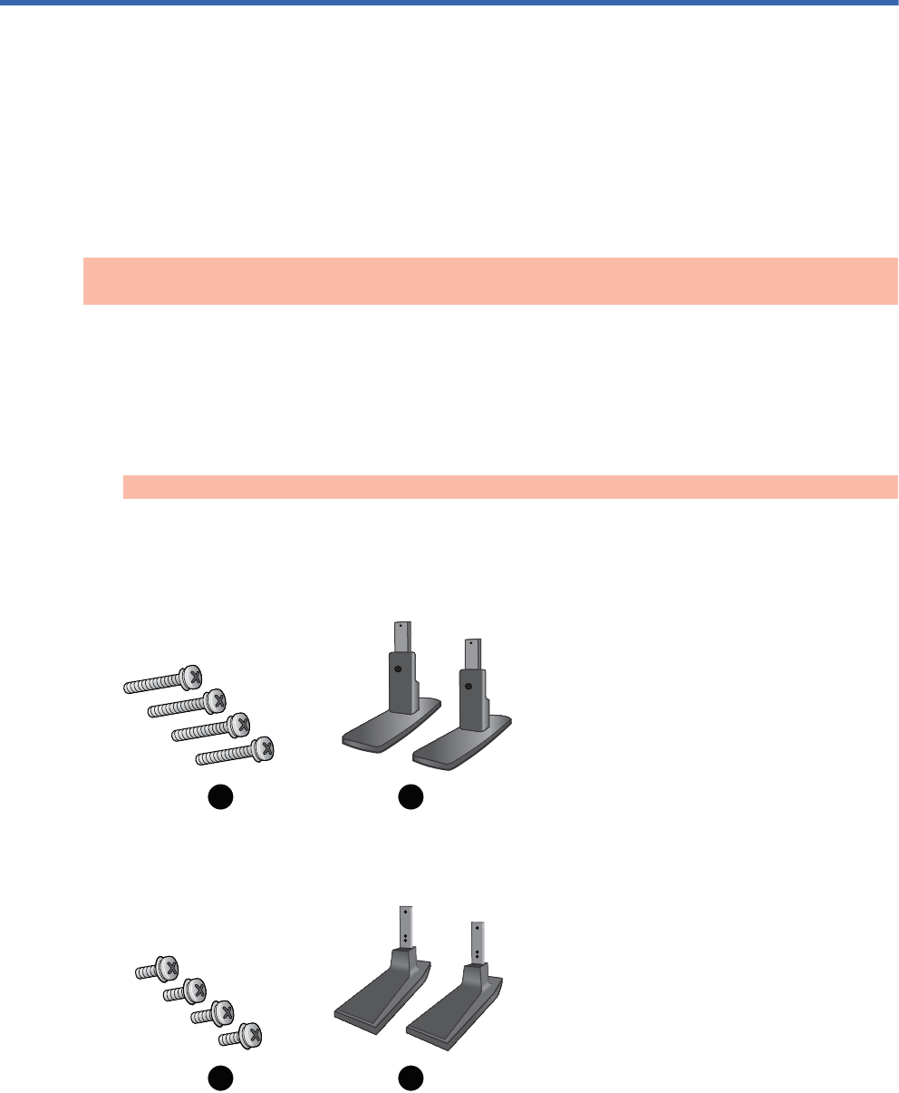
Take the parts for the stand out of the box.
łFor the HP LD4201 and LD4210—four screws M4 x 33 mm ( in) (1) and stand (2)
łHP LD4710—four screws M4 x 17 mm ( in) (1) and stand (2)
Figure 3-1 Stand accessory contents
1 2
1 2
ENWW Installing the stand (sold separately) 7
2
n
d
D
r
af
t
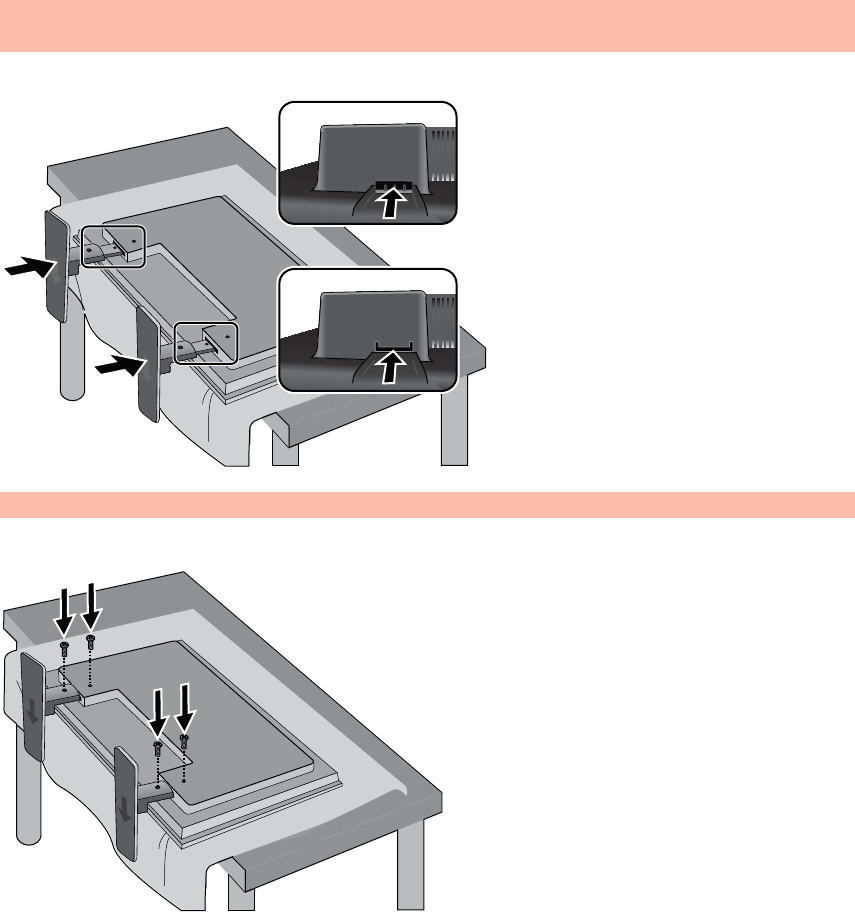
2. Place a soft cloth on the table and place the display with the screen facing downward. Connect
the stand as shown in the following figure.
Figure 3-2 Sliding the stand onto the display
3. Use the screws to secure the stand on the rear side of the product as shown in the figure.
Figure 3-3 Securing the stand to the display
8 Chapter 3 Setting up the display ENWW
2
n
d
D
r
af
t
Connecting the speakers (sold separately)
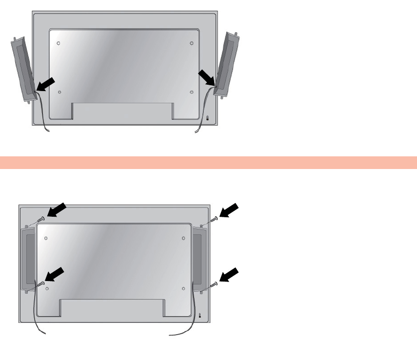
1. Mount the speakers onto the display.
Figure 3-4 Mounting the speakers
2. Use the four Taptite D3 x 12 mm (0.47 in) screws to secure the speakers to the display.
Figure 3-5 Securing the speakers to the display
ENWW Connecting the speakers (sold separately) 9
2
n
d
D
r
af
t
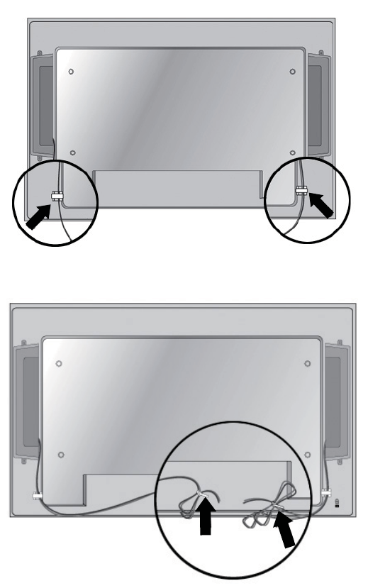
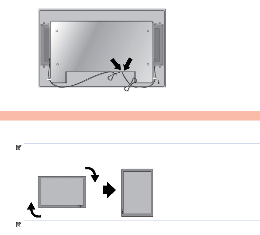
3. After installing the speakers, use the cable holders and cable ties (available on select models) to
organize the speaker cables.
Figure 3-6 Using the cable holders (feature available on select models)
Figure 3-7 Using the cable ties (feature available on select models)
10 Chapter 3 Setting up the display ENWW
2
n
d
D
r
af
t
4. After installing the speakers, connect the input terminal with a proper color match.
Figure 3-8 Connecting to the input terminal
Rotating to the portrait position
When installing the display in the portrait position, rotate it clockwise based on its front. The display
can be rotated in only one direction.
NOTE: The display cannot be rotated if it is installed on the stand.
Figure 3-9 Installing portrait
NOTE: The LED indicator light orientation is on the bottom-right corner in the landscape position
and on the bottom-left corner when rotated to the portrait position.
ENWW Rotating to the portrait position 11
2
n
d
D
r
af
t
Using the remote control
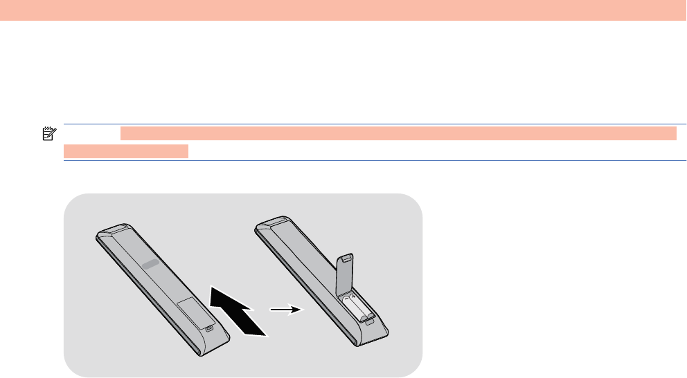
Inserting the batteries (sold separately)
1. Slide off the battery cover.
2. Insert the batteries with correct polarity (+/-).
3. Close the battery cover.
NOTE: To prevent environmental pollution, dispose of used batteries in accordance with your local
recycling guidelines.
Figure 3-10 Inserting batteries
12 Chapter 3 Setting up the display ENWW
2
n
d
D
r
af
t
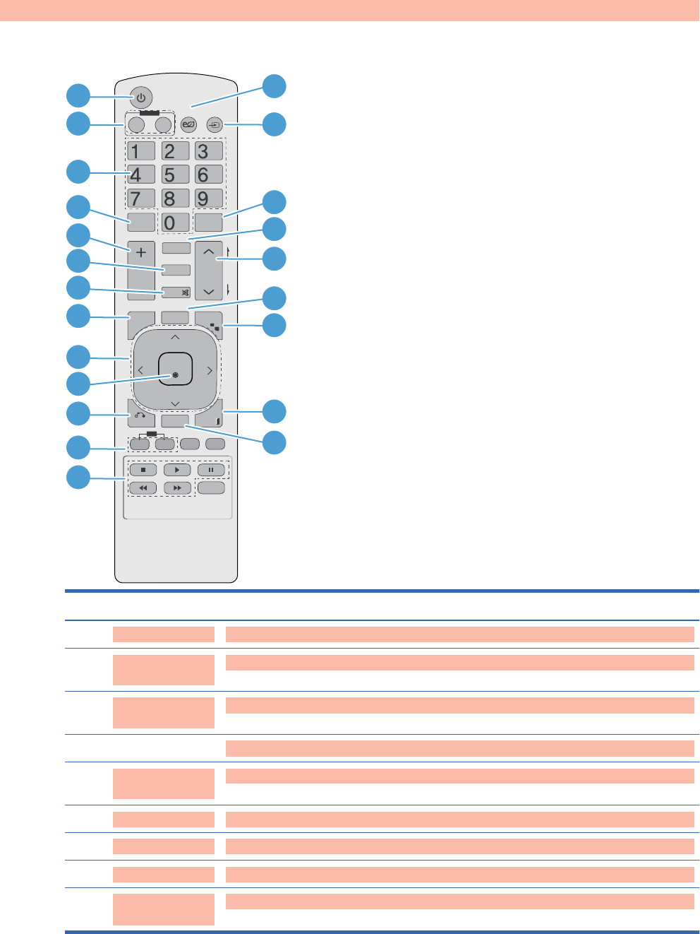
Identifying remote control buttons
Figure 3-11 Remote control buttons[Author note:]Graphic is being updated — component 4 and
16 are not supported and component 20 is now USB instead of S.Menu
P
A
G
E
INPUT
ENERGY
SAVING
MARK
ARC
ON
OFF
. , ! ABC DFG
GHI JKL MNO
PQRS TUV
- * #
WXYZ
OK
USB
MONITOR
PSM
AUTO
MUTE
BRIGHT
NESS
MENU
ID
BACK TILE
ON OFF
EXIT
1
2
3
8
11
12
13
9
10
6
7
4
5
14
15
18
20
21
22
16
17
19
Component Function
1Power on/off Turns the display on from standby or off to standby
2MONITOR ON or
OFF
Turns the display on and off
3Number and
alphabet
Types numbers and alphabet letters
4 Not supported
5Volume up (+) or
down (-)
Adjusts the volume
6PSM Selects the Picture Status Mode
7MUTE Turns the sound on or off
8MENU Selects a menu or clears all on-screen displays and returns to display viewing from any menu
9Up/down/left/right
arrows
Allows navigation of the On-Screen Display menus and adjustment of the system settings
ENWW Using the remote control 13
2
n
d
D
r
af
t
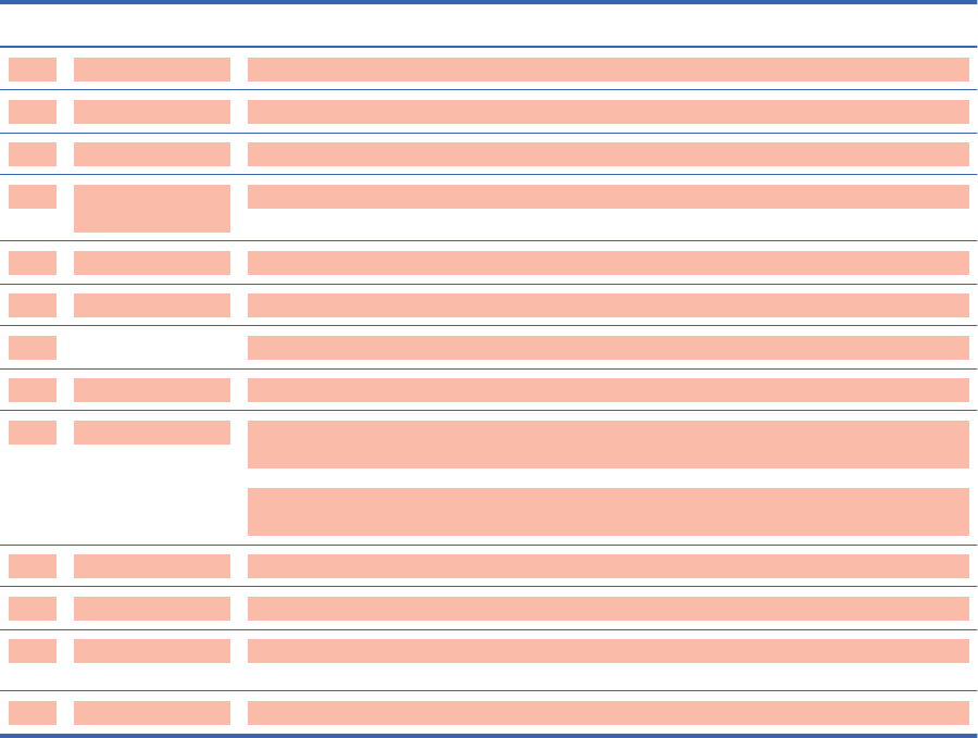
Component Function
10 OK Accepts a selection or displays the current mode
11 BACK Navigates one step back in an interactive application
12 ID ON or OFF Enables the display lock
13 USB menu control
buttons
Use with the HP Media Sign Player option lists in the USB menu
14 ENERGY SAVING Adjusts the Energy Saving mode
15 INPUT Opens the Input Source menu options (RGB, HDMI/DVI, and DisplayPort)
16 Not supported
17 ARC Selects the Aspect Ratio converter mode
18 BRIGHTNESS Adjusts the resolution and brightness by pressing the Up and Down buttons on the remote
control
In USB mode, the OSD menu uses the Page function of the BRIGHTNESS button to move to
the next file list.
19 AUTO Automatically adjusts picture position and minimizes image instability (RGB input only)
20 USB Opens the USB menu options
21 EXIT Clears all on-screen displays and returns to display viewing from any menu
22 TILE Selects the TILE Mode
14 Chapter 3 Setting up the display ENWW
2
n
d
D
r
af
t
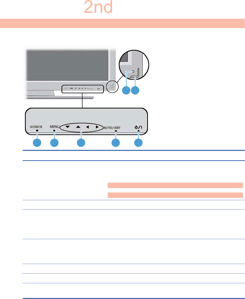
Identifying display components
Figure 3-12 Display components[Author note:]Update graphic —need new front and back
component graphics with callouts.
1 2 3 4 5
76
Component Function
1SOURCE Toggles between video inputs:
łHDMI/DVI - Digital signal
łRGB - 15-pin D-Sub analog signal
łDisplayPort
2MENU Opens or closes the OSD (On-Screen Display) menu screen.
3 OSD select/adjust buttons Selects an OSD menu icon or adjusts the settings in the OSD screen.
Down arrow ź and up arrow Ÿ buttons adjust up and down
Left arrow Ż and right arrow Ź buttons adjust the volume
4AUTO/SET When the OSD window is closed, the auto-adjustment feature to optimize the
screen image is activated.
When the OSD window is open, press to select a menu item or save changes.
5 Power Press to turn on the power. Press again to turn it off.
6 IR receiver Receives signals from the remote control.
7 LED indicator light Lights up blue when the display operates normally (on mode). If the display is in
sleep (Energy Saving) mode, the indicator color changes to amber.
ENWW Identifying display components 15
D
r
af
t
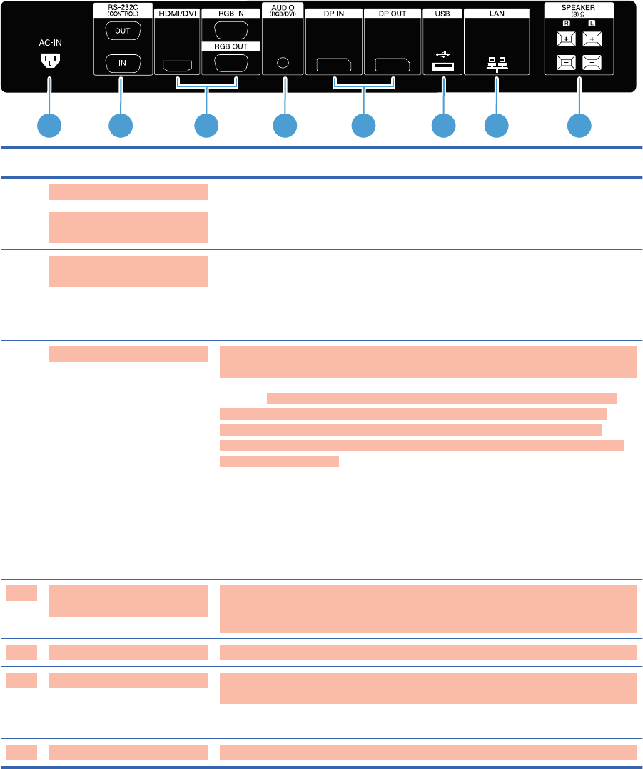
Figure 3-13 Display ports
1 2 3 4 5 6 7 8
Component Function
1AC-IN power AC-IN connects the AC power cord to the display.
2RS-232-C (Control) serial
ports
RS-232-C (Control) serial ports connect to RS-232 devices
3HDMI/DVI, RGB IN, and RGB
OUT
HDMI supports High Definition input and HDCP (High-bandwidth Digital Content
Protection). Some devices require HDCP in order to display HD signals. DVI input
is supported with an HDMI to DVI signal cable (not included). RGB IN supports
analog VGA connections from PCs. RGB OUT supports cloning connections with
VGA cables from display to display.
4AUDIO (RGB/DVI) AUDIO (RGB/DVI) connects the audio cable to the Line Out on the media player/
computer sound card.
NOTE: Before connecting to the AUDIO (RGB/DVI) port on the display, verify
what type of Audio Out connection is available on the media player/computer
sound card. The Line Out on a media player/computer is used to connect to
speakers, including a built-in amplifier (AMP). For additional instructions, refer to
the sound card manual.
If the Audio Out on the media player/computer sound card has only Speaker Out,
reduce the media player/computer volume before connecting to the AUDIO (RGB/
DVI) port on the display.
If the Audio Out on the media player/computer sound card supports both Speaker
Out and Line Out, choose Line Out.
5DP IN and DP OUT
(DisplayPort)
DP IN supports digital input with DisplayPort cables from a media player/
computer. DP OUT supports cloning of connections with DisplayPort cables from
display to display.
6USB USB connects a USB storage device to an HP Media Sign Player.
7LAN
(HP LD4210 and HP LD4710
models only)
LAN connects the display directly to a media player/computer or to a network
directly or indirectly by a router, hub, or switch using the LAN cable.
8SPEAKER SPEAKER connects the external speakers to the display.
16 Chapter 3 Setting up the display ENWW
2
n
d
D
r
af
t
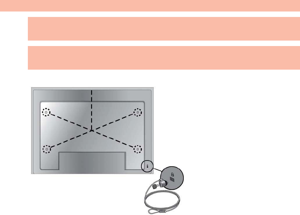
VESA mounting support and security slot
VESA FDMI (Video Electronics Standards Association Flat Display Mounting Interface) wall
mounting—This product supports a VESA FDMI-compliant mounting device. The mounting devices
can be purchased separately from HP.
Security cable provision—To help prevent theft, a security cable provision is available on the rear of
the display. The cable and lock required to connect to the display are available separately and can be
purchased from HP.
Figure 3-14 VESA mounting holes
ENWW VESA mounting support and security slot 17
2
n
d
D
r
af
t
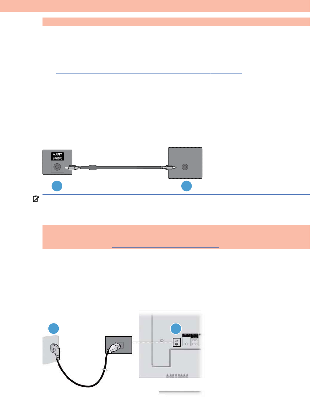
Connecting to external devices
1. Be sure that the display, media player/computer, and all attached devices are turned off.
2. Connect the signal input cable.
For additional information, see one of the following signal input cable sections:
łConnecting RGB on page 20
łConnecting DisplayPort (480p/576p/720p/1080i/1080p) on page 20
łConnecting HDMI (480p/576p/720p/1080i/1080p) on page 21
łConnecting LAN (HP LD4210 and HP LD4710 only) on page 22
3. Connect the audio cable (sold separately) to the Audio (RGB/DVI) (1) connector on the rear of
the display and the other end to the Line Out port (2) on the media player/computer if the video
signal connection is from either a RGB (VGA) or DVI connector on the media player/computer.
Figure 3-15 Connecting the audio
12
NOTE: The ferrite core can be used to reduce electromagnetic waves when connecting an
audio cable. As shown in the image, fit the ferrite core to the audio cable. The ferrite core needs
to be separated from the mold by 5 cm (2 in).
4. Connect the AC power cord to the AC-IN connector (1) on the rear of the display and the other
end to an electrical outlet (2). Before connecting the power cord, please read the power-cord
safety precautions in the Important safety information on page 3.
[Author note:]I have removed the Warning message that appeared below this step,
because it was identical to the Warning in the “Important safety information” section;
instead, I have referenced this safety section that contains the Warning message. Is this
ok?
Figure 3-16 Connecting the power cord[Author note:]Update graphic —Needs a new
graphic of the power cord.
1
2
18 Chapter 3 Setting up the display ENWW
2
n
d
D
r
af
t
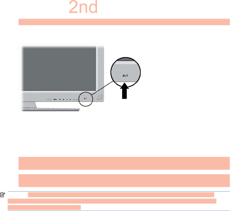
5. Turn on power to the display by pressing the power button.
Figure 3-17 Power button[Author note:]Update graphic-Needs a new graphic of front of
display.
6. Turn on the media player/computer.
7. Select an input signal.
Press the INPUT button on the remote control to open the Input List, select the appropriate
input signal (RGB, HDMI/DVI, DP), and then press the OK button to save your change.
Or, press the SOURCE button on the back of the display, and then press the AUTO/SET button
to save your change.
NOTE: If connecting more than one input source, connect the signal cables [HDMI/DVI, RGB
(VGA), and DisplayPort] to each media player/computer. Press the INPUT button on the remote
control to select the input to view.
ENWW Connecting to external devices 19
D
r
af
t
Connecting RGB
1. For analog operation, connect the D-Sub signal cable to the RGB IN (1) connector on the rear of
the display and the other end to the connector (2) on the media player/computer.
NOTE: If connecting to a Mac media player/computer, use the standard Mac adapter (3)—not
included.
Figure 3-18 Connecting the D-Sub signal cable
1
2
3
2. Connect the audio cable (sold separately) to the Audio (RGB/DVI) (1) connector on the rear of
the display and the other end to the Line Out port (2) on the media player/computer if the video
signal connection is from either a RGB (VGA) or DVI connector on the media player/computer.
3. Select an input signal.
Press the INPUT button on the remote control, select the RGB input signal, and then press the
OK button to save.
Or, press the SOURCE button on the back of the display, select the RGB input signal, and then
press the AUTO/SET button to save.
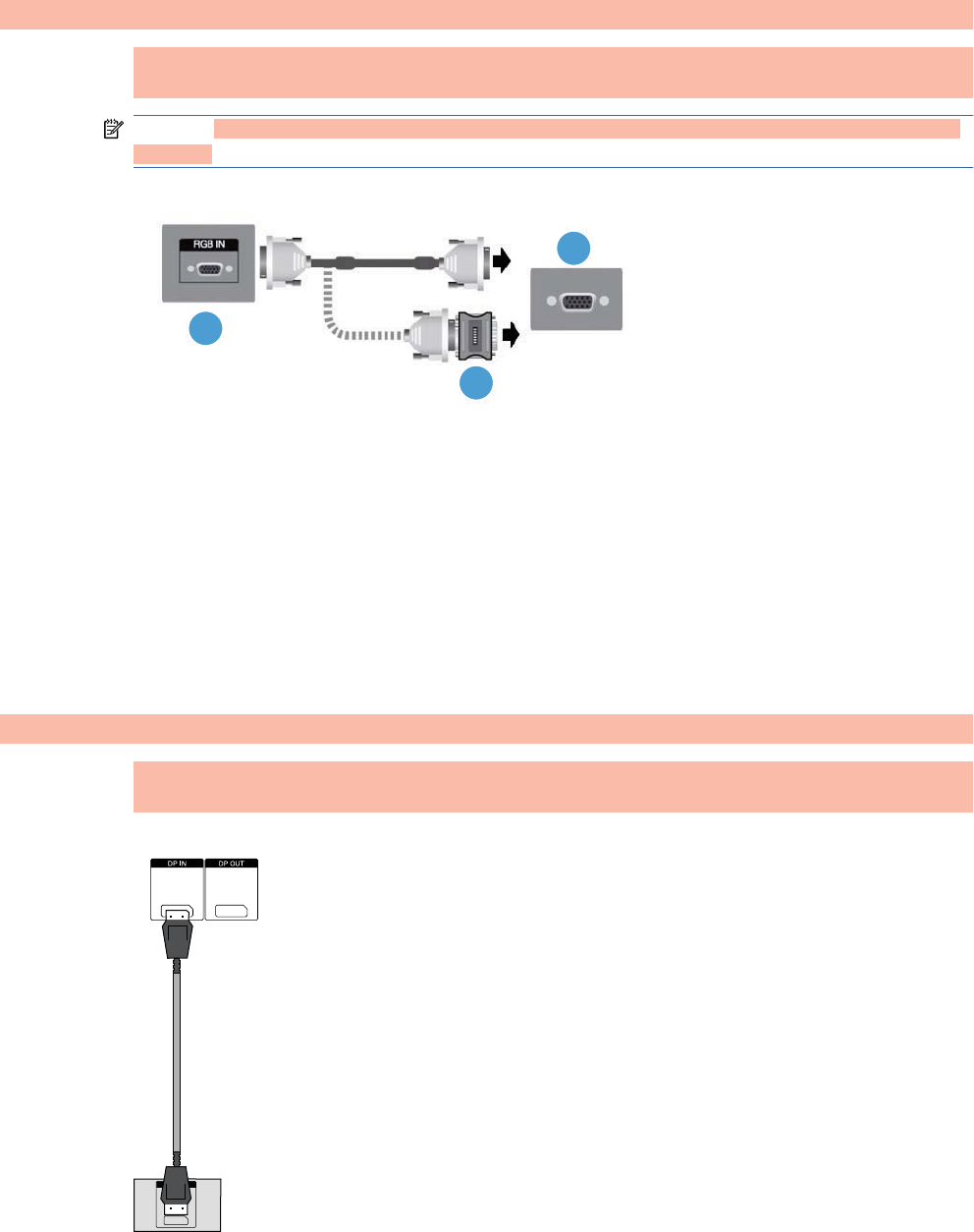
Connecting DisplayPort (480p/576p/720p/1080i/1080p)
1. Connect the DisplayPort cable to the DP IN port on the display and to the DisplayPort OUT port
on the media player/computer, and then connect the power cord.
Figure 3-19 Connecting DisplayPort input to a media player/computer
2. Select an input signal.
20 Chapter 3 Setting up the display ENWW
2
n
d
D
r
aft
Press the INPUT button on the remote control, select the DP input signal, and then press the OK
button to save.
Or, press the SOURCE button on the back of the display, select the DP input signal from the
Input List, and then press the AUTO/SET button to save.
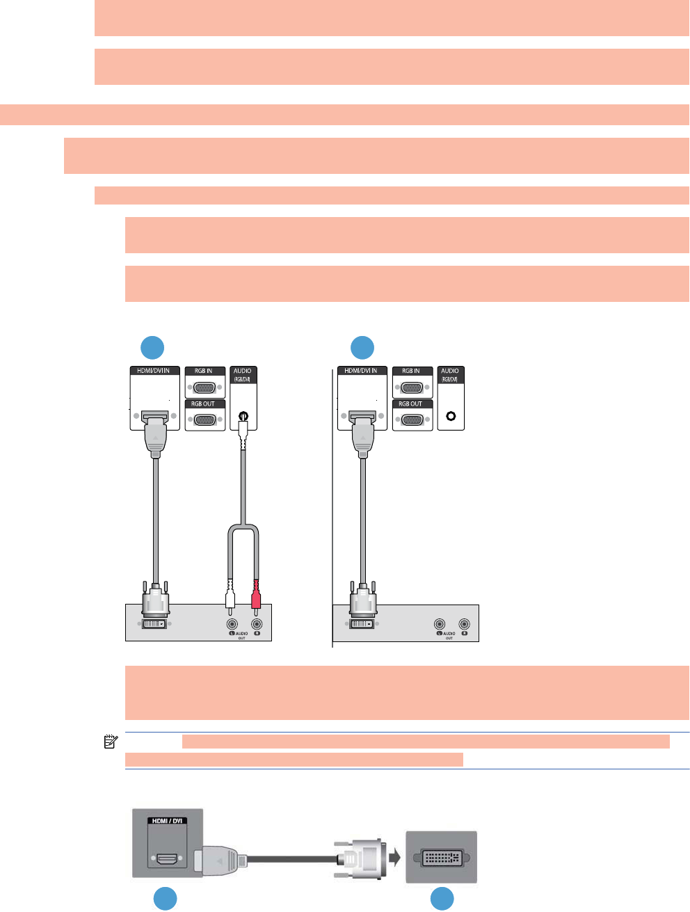
Connecting HDMI (480p/576p/720p/1080i/1080p)
HDMI supports High Definition Input and HDCP. Some devices require HDCP in order to display HD
signals.
1. Use one of the following examples to connect the HDMI input:
łConnect an HDMI to DVI signal cable and RCA-PC audio cable (cables not included) to the
display and VCR/DVD/Set-top box, and then connect the power cable (1).
łConnect an HDMI cable to the display and DVR/DVD/Set-top box, and then connect the
power cable (2).
Figure 3-20 Connecting HDMI input to VCR/DVD/Set-top box
12
łConnect the HDMI to DVI signal cable (not included) to the HDMI/DVI (1) connector on the
rear of the display and the other end to the DVI connector (2) on the media player/
computer.
NOTE: Use shielded signal interface cables (D-sub 15 pin cable, DVI cable) with ferrite
cores to maintain standard compliance for this product.
Figure 3-21 Connecting the HDMI to DVI signal cable
12
ENWW Connecting to external devices 21
2
n
d
D
r
af
t

łConnect the HDMI to HDMI signal cable (not included) to the HDMI/DVI (1) connector on
the rear of the display and the other end to the HDMI connector (2) on the media player/
computer.
Figure 3-22 Connecting the HDMI to HDMI signal cable[Author note:]Create graphic for
HDMI to HDMI?
2. Select an input signal.
Press the INPUT button on the remote control, select the HDMI/DVI input signal, and then press
the OK button to save.
Or, press the SOURCE button on the back of the display, select the HDMI/DVI input signal, and
then press the AUTO/SET button to save.
Connecting LAN (HP LD4210 and HP LD4710 only)
The LAN input on the display can connect to a media player/computer, a router (switch), or an
Intranet. A LAN connection with the display establishes communication between your media player/
computer and the display, which enables the use of the HP Network Sign Manager program running
22 Chapter 3 Setting up the display ENWW
2
n
d
D
r
aft
on the connected media player/computer to assign an IP address to the monitor, change monitor
settings, and set up HP Media Sign Player options, play lists, and On/Off schedule times.
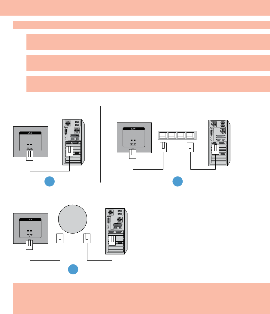
1. Connect the LAN cable (not included) using one of the following connections:
łComputer Direct Connection—Connect the LAN cable to the LAN port on the display and to
the LAN port on the media player/computer (1).
łRouter—Connect the LAN cable to the LAN port on the display and to a LAN port on the
router (2).
łIntranet—Connect the LAN cable to the LAN port on the display and to the Intranet network
via an access point (3).
Figure 3-23 Connecting the LAN cable
1 2
3
2. Install the HP Network Sign Manager on the media player/computer attached to the intranet. To
download the HP Network Sign Manager, see the website www.xxxxxxxxxx.com. See Installing
HP Network Sign Manager on page 47 for details on using the HP Network Sign Manager
application.
ENWW Connecting to external devices 23
2
n
d
D
r
aft
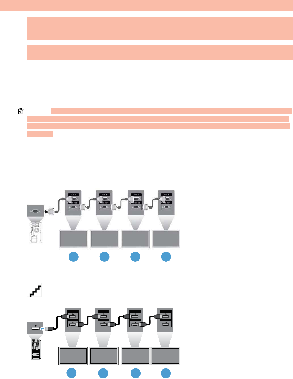
Connecting daisy chain displays
Multiple monitors (up to 25) can be connected in a daisy chain (connect several monitors together in
tile mode) to a computer using DisplayPort IN/OUT or with the combination of RGB IN/OUT and
RS-232-C IN/OUT ports on the display.
To connect displays in a daisy chain, the displays must all be connected with the same input/output
source (DisplayPort IN/OUT or RGB IN/OUT and RS-232-C IN/OUT) as shown in the figures below.
łTo daisy chain displays for video, use DisplayPort IN/OUT connections or RGB IN/OUT
connections.
łTo daisy chain for both video and display command and control, use DisplayPort IN/OUT plus
RS-232-C IN/OUT or RGB IN/OUT plus RS-232-C IN/OUT.
NOTE: The number of displays that can be connected by daisy chain to one media player/computer
might vary depending on the signal status and cable loss. If the signal status is good, and there is no
cable loss, it is possible to connect up to twenty-five displays in a daisy chain from one media player/
computer.
To connect multiple displays in a daisy chain, connect the input signal cable from the media player/
computer to the first display in the daisy chain and connect the subsequent displays, using the same
input signal cables, from the OUT port to the IN port of the next display, as shown in the figures
below, until all the displays are connected together.
Figure 3-24 Daisy chain connection—RGB for video input signal
123 4
Figure 3-25 Daisy chain connection—RGB for video input signals and RS-232-C for display
command and control[Author note:]Create graphic for daisy chain RGB and RS-232–C?
Figure 3-26 Daisy chain connection—DisplayPort for video input signal
Display In
Display Out
Display In
Display Out
Display In
Display Out
Display In
Display Out
12 3 4
24 Chapter 3 Setting up the display ENWW
2
n
d
D
r
af
t

Figure 3-27 Daisy chain connection—DisplayPort for video input signal and RS-232-C for display
command and control[Author note:]Create graphic for daisy chain DisplayPort and RS-232–C?
ENWW Connecting daisy chain displays 25
2
n
d
D
r
af
t
26 Chapter 3 Setting up the display ENWW
2
n
d
D
r
af
t

4 Operating the display
Software and utilities
HP displays are Plug-and-Play with Windows® XP, Windows Vista®, and Windows 7 operating
systems, so you do not need to download the .INF file or the .ICM file for these operating systems.
The most current versions of the following software and utilities can be downloaded from the following
HP website for use with the displays as needed: www.xxxx.com.
łAuto-adjustment Pattern Utility—optimizes the display.
łHP Network Sign Manager (HP LD4210 and HP LD4710 only)—allows you to select and control
the display options remotely from a connected media player/computer and allows you to select
the options for the HP Media Sign Player. For more details on the HP Media Sign Player, see
the Using the HP Media Sign Player chapter.
PDF Complete is supplied on this CD and can be installed from the menu.
NOTE: If the display does not include a CD, the .INF and .ICM files can be downloaded from the HP
displays support website. See Downloading from the Web on page 28 in this chapter.
The information file
The setup information, or .INF file, defines display resources used by Microsoft® Windows operating
systems to ensure display compatibility with the media player/computer’s graphics adapter.
The image color matching file
The image color matching, or .ICM file, is a color data file that is used in conjunction with graphics
applications to provide consistent color matching from display screen to printer, or from scanner to
the display screen. The .ICM file is only activated from within the graphics applications that support
this feature.
ENWW Software and utilities 27
2
n
d
D
r
af
t

Installing the .INF and .ICM files
You can install the .INF and .ICM files from the CD or download them from the HP displays support
website.
Installing from the CD
To install the .INF and .ICM files on the media player/computer from the CD:
1. Insert the CD in the media player/computer CD-ROM drive. The CD menu appears.
2. View the Display Driver Readme file.
3. Select Install display driver software.
4. Follow the on-screen instructions.
5. Ensure that the proper resolution and refresh rates appear in the Windows Display control panel.
NOTE: You might need to install the digitally signed display .INF and .ICM files manually from the
CD in the event of an installation error. Refer to the Display Driver Readme file on the CD for
instructions (in English only).
Downloading from the Web
To download the latest version of .INF and .ICM files from the HP displays support website:
1. Refer to www.hp.com/support and select the country/region.
2. Follow the links for the display to the support page and download page.
3. Ensure the system meets the requirements.
4. Download the software by following the instructions.
28 Chapter 4 Operating the display ENWW
2
n
d
D
r
aft

Using the auto-adjustment function (RGB INPUT source
only)
You can optimize the screen performance by using the AUTO/SET button on the display (AUTO
button on the remote control) and the Auto-adjustment Pattern Utility software on the CD provided.
NOTE: Do not use this procedure if the display is set to use a DisplayPort or HDMI/DVI input
source.
If the monitor is using a PC analog signal input, this procedure can correct the following image quality
conditions:
łFuzzy or unclear focus
łGhosting, streaking or shadowing effects
łFaint vertical bars
łThin, horizontal scrolling lines
łAn off-center picture
To use the auto-adjustment feature:
1. Allow the display to warm up for 20 minutes before adjusting.
2. Press the AUTO/SET button.
If the result is not satisfactory, continue with the procedure.
3. Insert the CD in the disc drive. The CD menu appears.
4. Select Open auto-adjustment software. The setup test pattern appears.
5. Press the AUTO/SET button to produce a stable, centered image.
6. Press the ESC key or any other key on the keyboard to exit the test pattern.
ENWW Using the auto-adjustment function (RGB INPUT source only) 29
2
n
d
D
r
aft
Using the On-Screen Display menu
The display settings can be adjusted from the On-Screen Display (OSD) menu.
Icon Main menu Function description
Picture Adjusts screen brightness, contrast, and color
Audio Adjusts the audio options
Time Adjusts the timer options
Option Adjusts the screen status according to the circumstances
Tile Adjusts the tile options
USB Adjusts the USB options
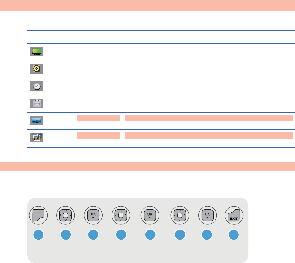
Using the remote control to adjust the OSD
Use the OSD to adjust the screen image based on your viewing preferences. To access the OSD, do
the following:
MENU
DD D D DDD
1 2 3 4 5 6 7 8
1. If the display is not already on, press the power button to turn on the display.
2. Press the MENU button (1) on the remote control.
3. To access a control, use the down arrow ź or up arrow Ÿ button (2).
4. When the icon you want becomes highlighted, press the OK button (3).
5. To access a control, use the down arrow ź or up arrow Ÿ button (4).
6. When the list you want becomes highlighted, press the OK button. (5).
7. Use the down arrow ź, up arrow Ÿ, left arrow Ż, or right arrow Ź button (6) to adjust the item
to the desired level.
8. Accept the changes by pressing the OK button (7).
9. Exit the OSD menu by pressing the EXIT button (8).
30 Chapter 4 Operating the display ENWW
2
n
d
D
r
aft

OSD menu selections
The following table lists the On-Screen Display (OSD) menu selections and their functional
descriptions.
Icon Main menu Submenu Description
PICTURE Aspect Ratio Selects from the following screen image sizes:
ł16:9—widescreen mode.
ł1:1—the picture format is 1:1 aspect ratio.
łJust Scan—allows you to enjoy the transmitted data fully
without any images cut off. (This menu is activated only
in 720p and 1080i in Component mode.)
łOriginal—the aspect ratio is not adjusted from the
original. It is set by the program being watched.
ł4:3—the picture format is 4:3 aspect ratio.
ł14:9— programs are viewed normally in 14:9 with black
bars added to the top and bottom. The 4:3 programs are
magnified on the top/bottom and left/right sides.
łZoom—4:3 programs are magnified until they fill the 16:9
screen. The top and bottom will be cut off.
łCinema Zoom 1—adjusts the picture both horizontally
extended and vertically cropped. The picture adopting a
compromise between alteration and screen coverage.
Energy Saving Select from the following screen brightness levels:
łOff—100% light
łLevel 1—80% light
łLevel 2—60% light
łLevel 3—40% light
ENWW Using the On-Screen Display menu 31
2
n
d
D
r
af
t

Icon Main menu Submenu Description
Picture Mode Select from the following screen presets:
łStandard—the most general and natural screen display
status.
łVivid—select to display with a sharp image.
łCinema—lowers brightness by one level.
łSport—displays with a soft image.
łGame—to enjoy dynamic image when playing a game.
łExpert 1 and Expert 2—allows user-defined settings:
ŃBacklight—controls the brightness of the screen,
adjust the brightness of the LCD panel.
ŃContrast—adjusts the difference between the light
and dark levels.
ŃBrightness—adjusts the brightness of the screen.
ŃSharpness, H Sharpness, and V Sharpness—
adjusts the clearness of the screen.
ŃColor—adjusts the color to desired level.
ŃTint—adjusts the tint to a desired level.
NOTE: If the Picture Mode setting in the Picture menu is set
to Vivid, Standard, Cinema, Sport, or Game, the subsequent
menus will be automatically set.
32 Chapter 4 Operating the display ENWW
2
n
d
D
r
af
t

Icon Main menu Submenu Description
Advanced
Control
Select from the following screen color adjustment settings:
łColor Temperature—select from the following color
settings:
ŃCool—slightly purplish white.
ŃMedium—slightly bluish white.
ŃWarm—slightly reddish white.
łDynamic Contrast—optimizes the contrast automatically
according to the brightness of the reflection.
łDynamic Color—adjusts the color of the reflection
automatically to reproduce natural colurs as close as
possible.
łNoise Reduction—removes the noise up to the point
where it does not damage the original picture.
łGamma—set your own gamma value. On the display,
high gamma values display whitish images and low
gamma values display high contrast images.
łBlack Level—adjusts the contrast and the brightness of
the screen using the black level of the screen.
ŃLow—The reflection of the screen gets darker.
ŃHigh—The reflection of the screen gets brighter.
łFilm Mode—adjusts the display, when watching a movie,
to the best picture appearance.
ENWW Using the On-Screen Display menu 33
2
n
d
D
r
af
t

Icon Main menu Submenu Description
Expert 1 and
Expert 2
Control
Select from the following settings:
łDynamic Contrast—optimizes the contrast automatically
according to the brightness of the reflection.
łNoise Reduction—removes the noise up to the point
where it does not damage the original picture.
łGamma—set your own gamma value. On the display,
high gamma values display whitish images and low
gamma values display high contrast images.
łBlack Level—adjusts the contrast and the brightness of
the screen using the black level of the screen.
łFilm Mode—adjusts the display, when watching a movie,
to the best picture appearance.
łColor Standard—adjusts color.
łWhite Balance—adjusts the overall color of the screen
to the feeling you want.
łColor Management System—adjusts by using test
patterns. This does not affect other colors but can be
used to selectively adjust the 6 color areas (Red/ Green/
Blue/Cyan/Magenta/Yellow). Color difference might not
be distinctive even when you make the adjustments for a
general video.
Picture Reset Returns the Picture Mode to the default factory settings.
Screen Select from the following screen video settings:
łResolution—to view a normal picture, match the
resolution of RGB mode and selection of PC mode.
(Function works in the following mode: RGB [PC] mode.)
łAuto Config. (RGB PC input only)—automatic
adjustment of the screen position, clock, and phase.
(Function is available for analog signals only.)
łPosition—moves the screen position.
łSize—adjusts the size of the screen.
łPhase—adjusts the focus of the display. This item allows
you to remove any horizontal noise and clear or sharpen
the image of characters. (Function is available for analog
signals only.)
łReset—returns Manual Config. to the default factory
settings.
AUDIO Auto Volume Adjusts uneven sound volumes across all channels or signals
automatically to the most appropriate level.
To use this feature, select On; to turn off the feature, select
Off.
34 Chapter 4 Operating the display ENWW
D
r
af
t

Icon Main menu Submenu Description
Clear Voice II Differentiates the human sound range from other sounds,
which helps to make the human voices easier to hear.
To use this feature, select On; to turn off the feature, select
Off.
Balance Balances sound between the left and right speakers.
Sound Mode Automatically selects the best sound tone quality, depending
on the video type that you are currently watching, from the
following options:
łStandard—most commanding and natural audio.
łMusic—select for original sound when listening to music.
łCinema—select for sublime sound.
łSport—select for sports broadcasting.
łGame—select for dynamic sound when playing a game.
Treble Adjust treble 0–100.
Bass Adjust bass 0–100.
Reset Resets the Sound Mode to the factory default settings.
Speaker Adjusts internal speaker status (speakers sold separately).
To use this feature, select On; to turn off the feature, select
Off.
To use an external hi-fi stereo system, turn off the internal
speakers of the display.
DisplayPort
Audio Out
Select DisplayPort or Analog.
TIME Clock Resets the Day, Hour, and Minute if the current time is
incorrect.
On Time The on time automatically switches the display on at the pre-
set time.
Off Time The off time automatically switches the display to standby at
the pre-set time.
Sleep Timer Automatically turns off power when the time set by a user has
passed.
Auto Off If active and there is no input signal, the display switches to off
mode automatically after 10 minutes.
Power On Delay When connecting multiple displays and turning the power on,
the displays are turned on individually to prevent overload.
OPTION Language Selects the language in which the OSD menu is displayed.
Input Label Selects a label for each input source.
ENWW Using the On-Screen Display menu 35
2
n
d
D
r
af
t

Icon Main menu Submenu Description
Key Lock Sets up the display so that it can only be used with the remote
control.
This feature can prevent unauthorized viewing.
Set ID Use to assign a unique Set ID NO (name assignment) to each
product when several products are connected for display.
ISM Method Image Sticking Minimalization Method—avoids allowing a
fixed or burn-in image to remain on the screen for a long
period of time.
DPM Select Display Power Management Select—Turns the power saving
mode On or Off.
Power Indicator Sets the power indicator on the front of the display to On or
Off.
DDC-CI To use this feature, select On; to turn off the feature, select
Off.
DFC Digital Fine Contrast—To use this feature, select On; to turn
off the feature, select Off.
Interface Select Sets up network connections.
łRS-232C—Enables communication via Serial.
łNetwork—Enables communication via Ethernet.
Network Setup DHCP—Allocates and sets up IP automatically.
IP Mode Manual—Sets up IP Address, Gateway, Subnet Mask, and
DNS Server.
Information Contains the Serial No., SW Version (MNT), SW Version
(LAN), IP Address, and MAC Address information.
Factory Reset Resets to the default factory settings.
TILE Tile Mode Enlarges the screen and is also used with several products to
view the screen.
To use Tile Mode, the following must occur:
łIt must be displayed with several other products.
łIt must be in a function that can be connected to RS-232-
C OUT, RGB OUT, or DisplayPort OUT.
Tile ID Selects the location of the Tile by setting an ID of 1–25.
Natural Mode The image is omitted by the distance between the screens to
be naturally shown.
To use this feature, select On; to turn off the feature, select
Off.
H Size Adjusts the horizontal size of the screen taking into account
the size of the bezel.
36 Chapter 4 Operating the display ENWW
2
n
d
D
r
af
t

Icon Main menu Submenu Description
V Size Adjusts the vertical size of the screen taking into account the
size of the bezel.
H Position Moves the screen position horizontally.
V Position Moves the screen position vertically.
Reset Resets the Tile Mode configuration.
USB Photo List View photo files on a USB storage device.
Music List Play music files on a USB storage device.
Movie List Play movie files on a USB storage device.
Lock System Sets the password function to On or Off.
To use this feature, select On; to turn off the feature, select
Off.
Set Password Sets or changes the password to use the USB function.
Selecting an Aspect Ratio
The aspect ratio modes available for your selection depend on the current input source. Use the
following table to determine which mode is available for your display.
Mode
ARC
DisplayPort
DTV
DisplayPort
PC
RGB
PC
HDMI/DVI
DTV
HDMI/DVI
PC
16:9 X X X X X
Just Scan X X
Original X X X X
4:3 X X X X X
1:1 X X X
14:9 X X
Zoom X X
Cinema Zoom 1 X X
Adjusting the timer function
Use the remote control to set the following timer options.
ENWW Using the On-Screen Display menu 37
2
n
d
D
r
aft

Clock
The Clock menu allows you to reset the clock manually if the current time is incorrect.
1. Press the MENU button, and then use the down arrow ź or up arrow Ÿ button to select the
TIME menu.
2. Press the right arrow Ź button, and then use the down arrow ź or up arrow Ÿ button to select
the Clock menu.
3. Press the right arrow Ź button, and then use the down arrow ź or up arrow Ÿ button to set the
hour (00h–23h).
4. Press the right arrow Ź button, and then use the down arrow ź or up arrow Ÿ button to set the
minutes (00–59 min).
On Time and Off Time
The On Time and Off Time menus lets you set the display to automatically switch to standby at a
pre-set time.
1. Press the MENU button, and then use the down arrow ź or up arrow Ÿ button to select the
TIME menu.
2. Press the right arrow Ź button, and then use the down arrow ź or up arrow Ÿ button to select
On Time or Off Time.
3. Press the right arrow Ź button, and then use the down arrow ź or up arrow Ÿ button to set the
hour (00h–23h).
4. Press the right arrow Ź button, and then use the down arrow ź or up arrow Ÿ button to set the
minutes (00–59 min).
5. Press the right arrow Ź button, and then use the down arrow ź or up arrow Ÿ button to select
On or Off.
NOTE: Once the On Time or Off Time is set, these functions operate daily at the preset time. The
Off Time function overrides the On Time function if they are set to the same time. When the On
Time is operated, the input screen is turned on just as it was turned off.
Sleep Timer
The Sleep Timer menu lets you set the display power to automatically turn off when the time set by a
user has passed.
1. Press the MENU button, and then use use the down arrow ź or up arrow Ÿ button to select the
TIME menu.
2. Press the right arrow Ź button, and then use the down arrow ź or up arrow Ÿ button to select
the Sleep Timer menu.
38 Chapter 4 Operating the display ENWW
2
n
d
D
r
aft

3. Press the right arrow Ź button, and then use the down arrow ź or up arrow Ÿ button to set the
hour (00h–23h).
4. Press the right arrow Ź button, and then use the down arrow ź or up arrow Ÿ button to set the
minutes (00–59 min).
NOTE: In the event of a power interruption (disconnection or power failure), the Sleep Timer clock
must be reset.
Auto Off
To set the display to switch to the off mode automatically after 10 minutes if Auto Off is active and
there is no input signal:
1. Press the MENU button, and then use the down arrow ź or up arrow Ÿ button to select the
TIME menu.
2. Press the right arrow Ź button, and then use the down arrow ź or up arrow Ÿ button to select
the Auto Off menu.
3. Press the right arrow Ź button, and then use the down arrow ź or up arrow Ÿ button to select
On or Off.
Power On Delay
When connecting multiple displays and turning the power on, the displays are turned on individually
to prevent overload.
Using Key Lock
The display can be set up so you can only use the remote control. To lock or unlock the OSD screen
adjustment:
1. Press the MENU button, and then use the down arrow ź or up arrow Ÿ button to select the
OPTION menu.
2. Press the right arrow Ź button, and then use the down arrow ź or up arrow Ÿ button to select
the Key Lock menu.
3. To lock the OSD screen adjustment, press the right arrow Ź button, and then use the down
arrow ź or up arrow Ÿ button to select On.
4. To unlock the OSD screen adjustment, press the MENU button on the remote control, and then
use the down arrow ź or up arrow Ÿ button to select Off.
ENWW Using the On-Screen Display menu 39
2
n
d
D
r
aft

Using ISM Method
A frozen or still picture from a media player/computer/Video game that appears on the screen for a
prolonged period of time could result in a ghost image remaining even when you change the image.
To avoid a fixed or burn-in image to remain on the screen for a long period of time:
1. Press the MENU button, and then use the down arrow ź or up arrow Ÿ button to select the
OPTION menu.
2. Press the right arrow Ź button, and then use the down arrow ź or up arrow Ÿ button to select
the ISM Method menu.
3. Select one of the following menu options:
łNormal—leave on normal if you do not foresee image burn-in being a problem.
łOrbiter—might help prevent ghost images. However, it is best not to allow any fixed image
to remain on the screen. To avoid a permanent image on the screen, the screen will move
every 2 minutes.
łInversion—this function inverts the panel color of the screen. The panel color is
automatically inverted every 30 minutes.
łWhite wash—white wash fills the screen with solid white. This helps to remove permanent
images burned into the screen. A permanent image might be impossible to clear entirely
with white wash.
Using Tile Mode
Tile Mode is used to enlarge the screen and also used with several products to view the screen. This
function must be displayed with various other products and connected to RS-232-C or RGB Out.
Tile mode allows you to:
łChoose tile alignment and set the ID of the current product to set location
łSet column by row (c = 1, 2, 3, 4, 5; r = 1, 2, 3, 4, 5) up to 5 x 5
łConfigure an integration screen as well as configure one-by-one display
NOTE: Adjustments made to the settings will be saved only after pressing the OK button on the
remote control.
Figure 4-1 Tile Mode Enlarged screen
40 Chapter 4 Operating the display ENWW
2
n
d
D
r
af
t

5 Using the HP Media Sign Player
[Author note:]The content for this section came from pages 34–37 of the 1st Draft of this User
Guide- per Brian Dodge.
When you connect a USB storage device, the MY MEDIA menu appears with the options Photo List,
Music List, or Movie List.
NOTE: The MY MEDIA menu will not be displayed while the OSD is active, including the Menu,
EPG, or Schedule list.
CAUTION: Back up important files on the USB storage device before using with the display. Data
management is the responsibility of the user. Do not turn off the display or unplug the USB storage
device when the connected device is working. When a USB storage device is suddenly separated or
unplugged, the stored files or the device might be damaged.
Information about using a USB storage device
łOnly a USB storage device is recognizable.
łIf the USB storage device is connected through a USB hub, the device is not recognizable.
łA USB storage device using an automatic recognition program might not be recognized.
łA USB storage device which uses its own driver might not be recognized.
łThe recognition speed of a USB storage device is specific to each device.
łDo not connect a USB storage device which is artificially maneuvered on the media player/
computer. The device might cause the display to malfunction or fail to play the files. Only use a
USB storage device which has standard music files or image files.
łUse only a USB storage device which was formatted as a FAT16, FAT32, or NTFS file system
provided with the Windows operating system. If a storage device is formatted using a different
utility program, which is not supported by Windows, it might not be recognized.
łData in a USB storage device cannot be deleted or added in the NTFS file system.
łConnect power to a USB storage device that requires an external power supply; otherwise, the
device might not be recognized.
łConnect a USB storage device with the cable provided by the USB manufacturer. When using
other cables or an excessively long cable, the device might not be recognized.
łSome USB storage devices might not be supported or operate smoothly.
łA maximum of 999 files and folders can be recognized.
ENWW 41
2
n
d
D
r
af
t
łData in a USB storage device cannot be aligned. Up to 128 English characters can be
recognized as a file name.
łIf the USB is connected in Standby Mode, the USB device might be detected when the display
is turned on.
łThe recommended capacity is 1TB or less for a USB external hard disk and 32GB or less for
USB memory. Any device with more than the recommended capacity might not work properly.
łIf a USB external hard disk with a “power saving” function does not work, turn the USB external
hard disk off and on again.
42 Chapter 5 Using the HP Media Sign Player ENWW
2
n
d
D
r
af
t

Using Photo List
Use Photo List to view photo files on a USB storage device.
Information about using Photo List
łPHOTO (*.JPEG) supporting file
łBaseline—15360 x 8640
łProgressive—1024 x 768
łYou can view JPEG files only; non-supported files are displayed in the form of a bitmap.
Photo selection and menu options
łView—Display the selected item
łMark All—Mark all photos on the screen
łDelete—Deleted the selected photo item
łClose—Close the pop-up menu
Options on full-sized photo view
łSlideshow—When no picture is selected, all photos in the current folder are displayed during
slide show. If some photos are selected, those photos are displayed in a slide show. Set the time
interval of the slide show in Option.
łBGM (Background Music)—Listen to music while viewing photos in full-size view. Before using
this function, set the Music Folder for BGM in Options.
łRotate icon—Use the rotate icon to rotate the photo 90°, 180°, 270°, or 360° clockwise. You
cannot rotate when the width of a picture is bigger than the supported height.
łDelete—Deletes photos.
łOption—Set values for Slide Speed and Music Folder for BGM. Use the down arrow ź, up
arrow Ÿ, left arrow Ż, or right arrow Ź button and the OK button to set values. Press OK to
save the settings. You cannot change Music Folder while BGM is playing.
łHide—Hide the menu on the full-sized screen. To see the menu again on the full-sized screen,
press the OK button to display.
ENWW Using Photo List 43
D
r
af
t

Using Music List
Use Music List to play music files on a USB storage device.
NOTE: If you do not select any button for a while, the play information box will float as a screen
saver. Press the OK button to stop the screen saver.
Information about using Music List
łMUSIC (*.MP3) supporting file—Purchased music files (*.MP3) might contain copyright
restrictions; playback of these files might not be supported.
łDamaged or corrupted music does not play but displays 00:00 in playtime.
łBit rate 32 to 320kbps
łSampling rate MPEG1 layer 3: 32 kHz, 44.1 kHz, 48 kHz.
Music selection and menu options
The Play Ź, Pause II, Stop Ŷ, Reverse ŻŻ, and Forward ŹŹ buttons on the remote control are
also available to use when playing music.
łPlay (during stop)—Play the selected music titles. Once playback of a piece of music finishes,
the next selected one will be played. When there are no selected music titles to play, the next
one in the current folder will be played. If you go to a different folder and press the OK button,
the current music in playback will stop.
łPlay Marked—Play the selected music titles. Once a music finishes playing, the next selected
one will be played automatically.
łStop Play (during stop)—Stop the playing music titles.
łPlay with Photo—Start playing the selected music titles and then move to the Photo List.
łMark All—Mark all music titles in the folder.
łDelete—Delete the selected music titles.
łClose—Close the pop-up menu.
44 Chapter 5 Using the HP Media Sign Player ENWW
2
n
d
D
r
aft

Using Movie List
Use Movie List to play movie files on a USB storage device.
Information about using Movie List
łMOVIE (*.avi) supporting file
łVideo format—MPEG1, MPEG2, MPEG4 (does not support Microsoft MPEG 4-V2, V3)
łAudio format—Mpeg, Mp3, PCM, Dolby Digital
łSampling frequency—within 32k to 48 khz
łBit rate—32k to 320 kbps
łSubtitle format—*.smi/ *.srt/ *.sub (MicroDVD, SubViewer 2.0)/ *.ass/ *.ssa/*.txt (DVD Subtitle
System)
łIf the video and audio structure of recorded file is not interleaved, either video or audio is
outputted.
łMaximum FPS (frame per second) can be reached only at SD level. FPS is 25 FPS (720*576) or
30 FPS (720*480) depending on Resolution.
łFiles more than 25 FPS or 30 FPS or higher might not be played properly.
łA video file name and its subtitle file name must be identical for it to be displayed.
łPlaying a video via a USB connection that does not support high speed might not work properly.
łUSB storage devices below USB 2.0 are supported as well, but they might not work properly in
the Movie List.
łFiles encoded with GMC (Global Motion Compensation) might not be played.
File
Extension name
Video decoder Audio codec Max. resolution
mpg, mpeg, vob, dat MPEG1, MPEG2 AC3, MPEG, MP3, PCM 720 x 576 @ 25p
720 x 480 @ 30p
Avi, m4v MPEG4-SP, MPEG4-ASP,
Xvid
AC3, MPEG, MP3, PCM
Movie selection and menu options
łPlay—Play the selected movie
łMark All—Mark all movies in the folder
łDelete—Delete the selected movie item
łClose—Close the pop-up menu
ENWW Using Movie List 45
2
n
d
D
r
aft

Table 5-1 Using the remote control for movies
Reverse ŻŻ and Fast
Forward ŹŹ buttons
When the movie is in play mode, press the Reverse ŻŻ button repeatedly to increase the
reverse speedŻŻ (x2) ĺ ŻŻŻ (x4) ĺ ŻŻŻŻ (x8) ĺ ŻŻŻŻŻ (x16) 寯ŻŻŻŻ
(x32) . Press the Fast Forward ŹŹ button repeatedly to increase the forward speed
ŹŹ(x2) ĺ ŹŹŹ (x4) ĺ ŹŹŹŹ (x8) ĺ ŹŹŹŹŹ(x16) ĺ ŹŹŹŹŹŹ (x32).
When the movie is in play mode, press the Fast Forward ŹŹ button repeatedly to increase
the forward speed ŹŹ(x2) ĺ ŹŹŹ (x4) ĺ ŹŹŹŹ (x8) ĺ ŹŹŹŹŹ(x16) ĺ
ŹŹŹŹŹŹ (x32).
Pause II button During playback, press the Pause II button; a still screen appears. Press the Pause II button,
and then use the Forward ŹŹ button for slow motion. If no buttons are pressed on the
remote control for 10 minutes after pausing, the TV returns to the playback state.
Left arrow Ż and right
arrow Ź buttons
When using the left arrow Ż or right arrow Ź buttons during playback, a cursor indicating
the position can be viewed on the screen.
Play Ź button Press the Play Ź button to return to normal playback.
ENERGY SAVING button Press the ENERGY SAVING button repeatedly to change the brightness of your screen.
46 Chapter 5 Using the HP Media Sign Player ENWW
D
r
af
t

6 Installing HP Network Sign Manager
NOTE: The HP Network Sign Manager is available only for the HP LD4210 and HP LD4710 Digital
Signage Displays.
HP Network Sign Manager is a digital signage solution that consists of the signage display and
management software that supports a network connection to a commercial display and combines the
conventional USB playback feature to allow users to easily and simply enjoy media content at any
time they want.
HP Network Sign Manager is a management software to help you easily adjust the settings (e.g.
display and power on/off) of the monitors connected to the network or serial communications and play
media files stored in the USB device. It also allows you to group the monitors depending on the
purpose to manage the content playback list and playback schedule easily and efficiently.”
ENWW 47
D
r
aft
Signage display
The signage display has a built-in Ethernet network interface card to play different media files
simultaneously from different displays connected to the Internet or the local network and to control the
settings for each display separately.
48 Chapter 6 Installing HP Network Sign Manager ENWW
2
n
d
D
r
af
t

System requirements
CPU P1.8
RAM 256M
HDD 400M
Ethernet 100M
Operating system Windows XP (32 bit)
Windows Vista (32 bit)
Windows 7 (32 bit)
ENWW System requirements 49
2
n
d
D
r
af
t

Features
łIntegrated Control of LAN and Serial Communications—Ensures to easily manage the
display connected to the local network and serial communications.
łWide Area Network (WAN) Control—Efficiently controls the displays even at remote sites
through WAN such as Internet.
łAutomatic Search for displays on the Same Network—Automatically searches, adds, and
manages displays connected to the same network such as HP Network Sign Manager.
łSelf-diagnosis—Checks the failure of the connected displays in real time.
łPower on/off Scheduling and Input Signal Settings—Sets the display to be turned on/off the
automatically and sets an input signal to be applied when the display is turned on.
łEasy Tile Mode —Allows to set the tile mode with the easy-to-use and intuitive GUI design.
łFirmware Upgrade via LAN—Updates the display firmware easily via network.
łInstant Messaging—Allows to display a message you want on the screen.
łLog History—Logs and manages all events that occur in the HP Network Sign Manager
solution.
łAlarm—Automatically sends an alert message to the administrator if any problem occurs on the
display.
50 Chapter 6 Installing HP Network Sign Manager ENWW
D
r
af
t

Environment setup
The HP Network Sign Manager environment setup refers to connecting your signage display and the
HP Network Sign Manager program to the network. There are three networking methods supported
for the HP Network Sign Manager network setup:
łLocal Area Network (LAN)
łWide Area Network (WAN)
łRS-232 Serial Communication
Connecting a display via LAN or WAN
You can connect the display to the network directly or indirectly via a router, hub, or switch. Connect
the network cable that is connected to the LAN or WAN to the Ethernet port on the signage display.
Figure 6-1 Connecting a display via LAN or WAN[Author note:]Include this graphic from eZ-Net
Manager?
Setting IP address to the network display
Once the network cable is connected, set an IP address of the signage display to complete the
network connection.
Follow the steps below to set an IP address of the display:
1. Go to Menu on the display, and then select Option.
2. In the Option dialog, select Interface Select, and then select Network.
[Author note:]Need screen shot
3. In the Option dialog, select Network Setup. Select how to assign an IP address under IP
Mode. You can assign an IP address either manually or using DHCP connection.
łIf you choose to use the DHCP connection:
a. Click Apply to assign an IP address automatically.
b. Click Close to complete the IP address configuration.
łIf you choose to assign manually:
a. Configure an IP address, subnet mask, gateway, and DNS server address.
b. Click Apply to save the IP address configuration.
c. Click Close to complete the IP address configuration.
4. Return to the Option dialog, select Information, and then select IP Address to check whether
the IP address is properly assigned.
ENWW Environment setup 51
D
r
af
t

Connecting a display via RS-232-C serial port
Directly connect the display to the media player/computer where HP Network Sign Manager is
installed using an RS-232-C cable (sold separately). To connect more than one display to the media
player/computer, connect the first monitor to the media player/computer with an RS-232-C cable, and
then connect the rest of the displays with an RS-232-C cable.
Would this “Connecting ... RS-232-C” section be better placed in the “Connecting to external devices”
section?
Figure 6-2 Daisy chain connection—RS-232-C
NOTE: The number of displays that can be connected by daisy chain to one media player/computer
might vary depending on the signal status and cable loss. If the signal status is good, and there is no
cable loss, it is possible to connect up to twenty-five displays in a daisy chain from one media player/
computer.
52 Chapter 6 Installing HP Network Sign Manager ENWW
2
n
d
D
r
af
t

HP Network Sign Manager installation
Install HP Network Sign Manager on the media player/computer to be connected with the display and
to the network. HP Network Sign Manager installed on your media player/computer allows you to
control the display options and playback schedule.
Installing HP Network Sign Manager
1. Insert the HP Software and Documentation CD, that comes with the display, into the CD-ROM.
The HP Network Sign Manager Installation screen appears.
2. From the Home screen, select HP Network Sign Manager & Guide. The HP Network Sign
Manager & Guide screen appears.
3. Select HP Network Sign Manager. The HP Network Sign Manager Setup: Installation
Options dialog appears.
4. Select shortcut(s) to create during the installation, and then click Next. The HP Network Sign
Manager Setup: Installation Folder dialog appears.
5. Select a folder to install the HP Network Sign Manager program. Click Browse... to change the
installation directory.
6. Click Install. The installation of the HP Network Sign Manager starts in the selected folder.
7. When the installation is complete, the HP Network Sign Manager Setup: Installation
Completed dialog appears. Click Close to close the dialog.
Removing HP Network Sign Manager
This following describes how to uninstallHP Network Sign Manager from your computer:
1. Click Start, click All Programs, click HP Network Sign Manager, and then select Uninstall.
The HP Network Sign Manager Uninstall: Confirmation dialog appears.
2. Click Uninstall. The HP Network Sign Manager Uninstall: Completed window appears when
the HP Network Sign Manager program is successfully removed.
3. Click Close to close the dialog box.
ENWW HP Network Sign Manager installation 53
2
n
d
D
r
af
t

Quick overview
HP Network Sign Manager is a network-based integrated solution management program supporting
various features, including digital signage display control, image/video playback, and remote control.
Home screen
[Author note:]Need screen shot of Home screen
A Toolbar Provides functions commonly used in HP Network Sign Manager such as networked
display search/connection and communication configuration.
B Monitor Register Window Adds and manages networked displays.
C Control Tab Controls the settings of the selected display.
D Control Panel Displays and configures settings for the selected function in the one of the control
tabs.
Toolbar
Table 6-1 Provides functions commonly used in HP Network Sign Manager.[Author note:]Do you want a
single graphic with callouts or individual graphics in the left column of the table?
Search is used to find display(s) that can be connected to the network and add them in the Add Monitor
pane. The Search icon is enabled only when the communication configuration of HP Network Sign
Manager is set to Ethernet.
Setting is used to configure the communication method of HP Network Sign Manager. You can choose
either Ethernet or serial connection.
Connect is used to manually connect the selected display. The Connect icon is enabled only when the
communication configuration of HP Network Sign Manager is set to Ethernet.
Refresh is used to refresh the control panel information of HP Network Sign Manager.
Message is used to display an instant message on the selected display.
Alarm is used to send an alert message to the administrator if any problem occurs on the display or the
network.
Security is used to change the user ID and password of HP Network Sign Manager.
Help displays information about the HP Network Sign Manager program.
54 Chapter 6 Installing HP Network Sign Manager ENWW
D
r
af
t

Control tab
Table 6-2 The control tabs control the settings of the selected display.[Author note:]Do you want a
single graphic with callouts or individual graphics in the left column of the table?
Information displays information on the hardware, network, status, and failures of the display.
Control is used to control the power, input, volume, and OSD display settings of the display.
A/V is used to change the sound and video settings of the display.
Option is used to change the display of the display and settings of additional functions.
Schedule is used to configure the timer settings to turn on and off the display.
Tile is used to connect and set multiple displays.
USB is used to set the playback schedule for the medial files stored in the USB device.
Upgrade is used to upgrade the firmware of the display.
ENWW Quick overview 55
2
n
d
D
r
af
t

Log-in
The Log-in dialog appears when HP Network Sign Manager starts. You must log in to use
HP Network Sign Manager.
Enter your ID and password in the Log-in dialog, and then click OK. Then, you are returned to the
main window of HP Network Sign Manager.
NOTE: The ID and password are case-sensitive.
The default ID and password for HP Network Sign Manager are “Administrator” and “0000”
respectively.
You can change the password.
56 Chapter 6 Installing HP Network Sign Manager ENWW
2
n
d
D
r
af
t

Connection settings
HP Network Sign Manager supports both Ethernet and serial communications to connect to the
display. The following sections describe how to configure communication in HP Network Sign
Manager.
Ethernet communication settings
1. Click Setting on the toolbar of HP Network Sign Manager. The Setting dialog appears.
2. Select Network under Communication Select, and then click OK.
3. Click Yes to confirm and save the settings. The program exits upon confirmation. The new
settings will be applied the next time you start the program.
Serial communication settings
1. Click Setting on the toolbar of HP Network Sign Manager.
2. Select Serial under Communication Select dialog. Then, the Serial Setting fields become
activated.
3. When all fields are filled, click OK.
Item Description
Port Communication port (COM1 - COM9), Default: COM1
Baud Rate Communication speed (2400 - 115200), Default: 9600
Data Communication data (Data5 - Data8), Default: Data8
Parity Parity check (even, odd, none), Default: none
Stop The number of stop bits (0 - 1), Default: 1
Flow Control Data flow (Xon/Xoff, hardware, none), Default: none
4. Click OK to confirm and save the settings. The program exits upon confirmation. The new
settings will be applied next time you start the program.
NOTE: When you run HP Network Sign Manager for the first time, the communication is set to
Ethernet (Network) by default.
ENWW Connection settings 57
2
n
d
D
r
af
t
Display registration
HP Network Sign Manager allows you to add and manage multiple monitors with both Ethernet and
serial communications.
Registering a networked display
The following describes how to add a monitor with Ethernet communication.
1. Click Search on the toolbar. The Signage Monitor Search dialog appears.
2. Specify a Search Method in the Signage Monitor Search dialog. There are two search
methods:
łSubnet (Broadcasting) — Automatically searches monitor(s) on the same local network to
which the computer running HP Network Sign Manager is connected.
łEnter IP address manually — An IP address for the monitor needs to be entered manually
to add it to HP Network Sign Manager. Monitors connected to the external network can also
be connected.
NOTE: Sharing the same network means using the same default gateway and subnet
host.
3. Click Search to search for a monitor. When the search is complete, the Completed message
appears under Status.
4. When the search is complete, click Close to close the dialog. You can see the searched
monitor(s) added in the Add Monitor pane of the main window.
The added monitor is displayed with three different icons depending on the current status as shown below:
Successfully connected to HP Network Sign Manager
Disconnected from HP Network Sign Manager
When the fan, panel, or temperature is not normal
58 Chapter 6 Installing HP Network Sign Manager ENWW
2
n
d
D
r
af
t

Registering a display via serial communication
No extra search for displays is required when they are connected via serial communication using
HP Network Sign Manager. All displays connected via serial communication are displayed in the Add
Monitor pane.
A display connected via serial communication must have an ID assigned. HP Network Sign Manager
uses this ID to communicate with the display connected to the computer using the serial cable. To
control a monitor, select an ID of the monitor that you wish to control in the Add Monitor pane.
NOTE: If you select Monitor 0 in the Add Monitor pane, you can control all monitors regardless of
the IDs. However, controlling all monitors by selecting Monitor 0 prevents from receiving
acknowledgement (ACK) data from the monitors.
ENWW Display registration 59
2
n
d
D
r
af
t

Display and group management
HP Network Sign Manager supports to group and manage the monitors added in the Add Monitor
pane.
[Author note:]This sentence is confusing; what should it say?
Making a group
The following describes how to create a monitor group:
1. Right-click the group in the Add Monitor pane. The shortcut menu appears.
2. Click Make Group. The Make Group dialog appears.
3. Enter a group name in the Make Group dialog, and then click Set.
A new group is created under Group in the Add Monitor pane.
Adding a display to group
You can add monitors to the group you want and manage them by group.
The following describes how to add monitors to a group:
1. Right-click a monitor to group in the Add Monitor pane. The shortcut menu appears.
2. Click Add to Group from the shortcut menu. The Group Selection dialog appears.
3. Select a group to which the monitor is to be added under Group List.
The monitor is now added to the selected group.
NOTE: Alternatively, you can simply drag and drop a monitor to the group you want in the Add
Monitor pane.
Viewing group information
If you select a group in the Add Monitor pane, you can see a summary of all monitors included in the
group.
AStatus Displays the network connection status of the monitors included in the selected group.
BIP Address Displays the IP address of the monitors included in the selected group.
CTag Displays the tag of the monitors included in the selected group. This field appears as "- - - -" if
the monitor tag is not specified.
DPower Displays the power on/off of the monitors included in the selected group.
EInput Displays the input settings of the monitors included in the selected group.
FSignal Displays the signal status of the monitors included in the selected group.
60 Chapter 6 Installing HP Network Sign Manager ENWW
2
n
d
D
r
af
t

GFAN Displays the fan settings of the monitors included in the selected group.
HLAMP Displays the lamp settings of the monitors included in the selected group.
ITemp Displays the temperature settings of the monitors included in the selected group.
Deleting a group
You can delete a monitor and group added in the Add Monitor pane. The following sections describe
how to delete a monitor and group.
Deleting a group
1. Right-click a group to delete. The shortcut menu appears.
2. Click Remove Group from the shortcut menu. The selected group is now deleted.
Deleting a display from a group
1. Right-click a monitor to delete from a group. The shortcut menu appears.
2. Click Remove Monitor from the shortcut menu. The selected monitor is now deleted from the
group.
Deleting a display
You can completely delete a monitor added in the Add Monitor pane.
The following describes how to completely delete a monitor from the Add Monitor pane:
1. Right-click a monitor to delete under the Single node. The shortcut menu appears.
2. Click Remove Monitor from the shortcut menu. The selected monitor is now deleted.
NOTE: Deleting a monitor under Single in the Add Monitor pane will also delete the same monitor
added in the group.
Adding a tag to a display
By default, diplays added in the Add Monitor pane have only the IP address displayed. You can also
add a tag for each display to identify it easily.
The following describes how to add a tag to a display:
1. Right-click a display to add a tag. The shortcut menu appears.
2. Click Add Tag. The Add Tag dialog appears.
3. Enter a tag name in the New Tag field, and then click Set.
You can see the tag is added before the IP address of the display in the Add Monitor pane.
ENWW Display and group management 61
D
r
aft

Display configuration
HP Network Sign Manager can remotely control the connected monitors and changes their settings.
Viewing information
You can see details of the display configuration in the Information tab.
Display
The Display section shows the basic information on the selected display.
Item Description
Model Name Name
Serial Number Serial number
Monitor SW Version Software version
LAN SW Version Software version of LAN.
IP Configuration
The IP Configuration section allows you to configure a network for the selected display.
Item Description
IP Configuration Method IP configuration (DHCP/Static)
Network properties Network properties
Status
The Status section shows the current configuration of the selected display.
Item Description
Power Power on/off status
Input Input setting status
Signal Signal status
Screen Mute Screen on/off status
Volume Mute Sound on/off setting status
Picture Mode Screen mode status
Aspect Screen aspect ratio
62 Chapter 6 Installing HP Network Sign Manager ENWW
2
n
d
D
r
af
t
Diagnosis
The Diagnosis section shows display activities and failures.
Item Description
FAN Fan status
Lamp Lamp status
Power Power status.
Temperature (inside) Temperature inside the display
Controlling a display
The Control tab allows you to control the selected display.
Power
You can turn the display on or off with a mouse-click under Power. The color of the button changes
depending on the display status.
Item Description
When the display is turned on
When the display is turned off
The display is in energy-saving mode
NOTE: When the display is turned off or in energy-saving mode, you can use Power on, Volume
control, Signal check, Fan check, and Lamp check functions only.
Select Input
Use Select Input to select an input type supported in the display.
NOTE: The input type supported in the display might vary depending on the model.
Volume
Volume is used to adjust the position of the slider to set the volume between 0 and 100.
ENWW Display configuration 63
2
n
d
D
r
af
t

Screen Mute
Screen Mute is used to turn on or off the screen. Set to Mute On to play the sound only (no image/
video on the screen).
Volume Mute
Volume Mute is used to turn on or off the sound. Set to Mute On to play the image/video only on the
screen without sound.
OSD Select
OSD Select is used to turn on or off the OSD (on-screen display) of the display. Set to OSD Select
Off to not have the OSD appear on the screen.
NOTE: Note that you cannot configure the screen settings with a remote control or key operations
of the display when OSD Select is set to Off.
Configuring audio/video settings
You can change the audio and video settings of the selected display in the Control tab.
NOTE: Audio/video setting options might vary depending on the display model.
Picture Mode
Picture Mode is used to set the screen mode.
Backlight
Backlight is used to adjust the position of the slider between 0 and 100 to set the brightness of the
screen backlight.
Contrast
Contrast is used to adjust the position of the slider between 0 and 100 to set the contrast of the
screen.
Brightness
Brightness is used to adjust the position of the slider between 0 and 100 to set the brightness of the
screen.
Color
Color is used to adjust the position of the slider between 0 and 100 to set the color density of the
screen.
64 Chapter 6 Installing HP Network Sign Manager ENWW
2
n
d
D
r
af
t

Sharpness
Sharpness is used to adjust the position of the slider between 0 and 100 to set the sharpness of the
screen.
Color Temperature (White Balance)
Color Temperature (White Balance) is used to change the color temperature of the screen. You can
choose one from Normal (6500K), Cool (9300K), and Warm (5000K).
Auto Config
Auto Config is used to automatically configure the screen settings. When the display is connected to
the media player/computer with an RGB cable, click the Set button to automatically adjust the screen
position and minimize the screen flicker.
Sound Mode
Sound Mode is used to set the sound mode of the display.
Auto Volume
Auto Volume is used to turn on/off the auto volume adjustment function. Setting Auto Volume to On
will automatically adjust and optimize the display volume.
Balance
Balance is used to control the left and right speaker balance by adjusting the position of the slider
between -50 (left) and 50 (right).
Speaker
Speaker is used to turn on or off the display speaker. You can turn off the speaker when connecting
an external speaker to the display or when not in use.
Setting screen options
The Option tab allows you to change the screen settings of the selected display.
NOTE: Screen setting options might vary depending on the display model.
Aspect Ratio
Aspect Ratio is used to set the aspect ratio of the screen.
ISM Method
ISM Method is used to change the Image Sticking Minimization (ISM) method for the monitor. ISM
prevents an image-sticking phenomenon where a frozen still picture displayed on the screen for
prolonged periods can result in a ghost image.
ENWW Display configuration 65
2
n
d
D
r
aft

There are four ISM methods available in the display:
Image Sticking Method Description
Normal Does not use the ISM method.
White Wash Refreshes the screen into white to remove the ghost image.
Orbiter Moves the screen up/down/left/right every 2 minutes to remove the ghost
image.
Inversion Inverts the current screen color to remove the ghost image.
Power indicator
Power Indicator is used to enable or disable the power indicator of the display.
DDC-CI
DDC-CI is used to change the display DDC-CI setting.
DFC
DFC (Digital Fine Contrast)
DPM Select
DPM Select is used to change the display DPM (Dynamic Power Management) setting. Setting DPM
Select to On will automatically switch the display into the energy-saving mode when no image signal
is entered to the display.
Remote/Key Lock
Remote/Key Lock is used to lock or unlock the remote control and the keys on the display. Setting
Remote/Key Lock to Lock On will disable the remote control and keys on the display, preventing
you from controlling the display.
Sleep Timer
Sleep Timer is used to set the timer to go to the sleep mode. Once the specified time passes, the
display turns off automatically.
Auto Off
Auto Off is used to enable or disable the auto power off function. Setting Auto Off to On will turn off
the display if no image signal is detected for 10 minutes.
Power On Delay
Power On Delay is used to adjust the slider between 0 and 100 to set the delay time before turning
the display on. When turning more than one display at the same time, set Power On Delay of each
display to be different from each other to protect from overload.
66 Chapter 6 Installing HP Network Sign Manager ENWW
2
n
d
D
r
af
t

Energy Saving
Energy Saving is used to change the energy-saving mode.
Factory Reset
Factory Reset is used to reset the display to the factory default settings. Be careful with this option
because all settings will be reset.
Scheduling
The Schedule tab allows you to schedule the power on and off of the display.
Clock
Clock is used to set the current time of the display.
łSelect hour/minute/day, and then click Set to complete the time setting.
łClick Set by PC Time to synchronize the clock of the display to the clock of the computer where
HP Network Sign Manager is installed.
Time Schedule Setting
Time Schedule Setting is used to schedule the power on/off of the display.
The following describes how to schedule the power on/off of the display:
1. Select an option in the Repeat Set drop-down list to set the power on/off schedule. You can set
it to Daily, Monday to Friday, Monday to Saturday, Saturday to Sunday, or day of week.
2. Set both On Time (time to turn the display on) and Off Time (time to turn the display off). You
can specify On Time and Off Time separately by selecting each checkbox as shown below.
3. Set an input setting to use when the display is turned on. Selecting No change will keep the last
input setting.
4. Check whether the monitor On/Off Time settings are correct, and then click Set to save the
changes. You can see your display on/off schedule added under On/ Off Time Schedule Info.
On/Off Time Schedule Info
On/Off Time Schedule Info is used to check and manage the power on/off schedule of the display.
łTo delete the on/off schedule of the selected display, select a schedule (time) to delete, and then
click Delete. The on/off schedules of all selected displays are deleted.
łTo delete all schedules, select a list to delete, and then click Delete All. All the selected display
on/off times are deleted.
ENWW Display configuration 67
2
n
d
D
r
aft
Saving and loading display configuration
All display settings set in HP Network Sign Manager can be saved as a file. You can import the saved
settings later when necessary.
Saving display configuration
The following describes how to save the current display settings:
1. Right-click a display for which the settings are to be saved.
2. Click Save Configuration from the shortcut menu. The Save As... dialog appears.
3. Enter a file name, and then click Save. The Finish Save Configuration message appears when
it is successfully saved.
Loading display configuration
You can import (load) the saved settings to restore the display settings easily.
The following describes how to import the saved display settings.
1. Right-click a display for which the settings are to be imported and restored.
2. Click Load Configuration from the shortcut menu. The Open dialog appears.
3. Select the display settings file to import, and then click Open. The selected settings are imported
for the display, and the Load Configuration Status dialog shows the progress. The
Configuration load complete message appears when they are successfully imported.
68 Chapter 6 Installing HP Network Sign Manager ENWW
2
n
d
D
r
af
t

Tile Mode
The Tile mode allows you to connect more than one display and play a single media file
simultaneously from these connected displays.
Creating a tile mode
1. Select the Tile tab. The Tile Mode Wizard appears as shown below.
2. To create a new tile mode, select Create Tile Mode. To modify a previous tile mode, select
Adjust Tile Mode.
3. Select the number of columns and rows to create for the tile mode.
4. Select a display group to apply the tile matrix, and then click Set. The Set button is enabled only
when a display group is selected. Click Next.
NOTE: The tile size cannot exceed the maximum number of displays connected. A group of
displays must be properly configured in advance. The maximum size of tile mode supported is 5
x 5.
5. Assign a tile ID to each display of the group that you chose for the tile mode. This tile ID helps
you to identify the displays within the group. The display tile IDs are numbered from top-left (1 -
25). Click Next.
6. Set an input signal to use for each display within the group. The input signal type for each
display can be different within the same group.
7. Check whether the the display ID, tile ID, input signal type, and tile size are set correctly, and
then click Apply.
8. Click OK to confirm and exit the Tile Mode Wizard.
Modifying a tile mode
The following describes how to modify the previous tile mode.
1. Select the Tile tab. The Tile Mode Wizard appears.
2. To modify a previous tile mode, select Adjust Tile Mode. The Tile Mode Summary dialog
appears.
3. Modify the tile mode as necessary.
ENWW Tile Mode 69
2
n
d
D
r
aft

Schedule and Playback contents (USB)
This function allows you to set the playback schedule of HP Network Sign Manager. All files to play
should be saved in a separate USB device and then connected to the USB port on the display. The
playback schedule can be set to weekday, weekend, day of week, or daily.
Scheduling the playback of files
Set the playback schedule of HP Network Sign Manager.
USB Schedule
USB Schedule allows you to schedule the playback of media files saved in the USB device
connected to the display. USB Schedule has three sections: File List, Schedule List, and Repeat
Set.
File List Lists the media files in the USB device connected to the display.
łSelect All—Selects all media files in File List.
łClear All—Deselects all media files in File List.
łAdd Schedule List—Adds the selected file to Schedule List.
Schedule List Lists the media files to play on the display.
łUp—Moves up the selected file in Schedule List.
łDown—Moves down the selected file in Schedule List.
łDelete—Removes the selected file from Schedule List.
łDelete All—Removes all files from Schedule List.
Repeat Set Schedules the playback time (duration) of the media file(s).
łRepeat Set—Schedules the playback of media files.
There are 12 options of repetition playback.
Repetition option Description
Always Plays the file all the time. You do not need to set a specific playback schedule with this option.
Daily Plays the file everyday for the specified time period.
Mon–Fri Plays the file for the specified time period from Monday to Friday.
Mon–Sat Plays the file for the specified time period from Monday to Saturday.
Sat–Sun Plays the file for the specified time period from Saturday to Sunday.
Sun Plays the file for the specified time period on Sunday.
70 Chapter 6 Installing HP Network Sign Manager ENWW
2
n
d
D
r
af
t

Repetition option Description
Mon Plays the file for the specified time period on Monday.
Tue Plays the file for the specified time period on Tuesday.
Wed Plays the file for the specified time period on Wednesday.
Thu Plays the file for the specified time period on Thursday.
Fri Plays the file for the specified time period on Friday.
Sat Plays the file for the specified time period on Saturday.
łApply—Saves the playback schedule.
łCancel—Deletes the current playback schedule set for the display.
łOption—Sets the playback schedule option
łBack—Moves back to the USB function selection view.
Saving files in the USB device
Before you schedule the playback of files, all media files to play on the display should be saved in the
USB device separately. Use the Windows Explorer to save the media files to your USB device.
The following describes how to save media files directly to the USB device:
1. Connect the USB device to the media player/computer. When the USB device appears in the My
Computer window, double-click the USB device.
2. Copy the media file(s) to play to the USB root directory.
NOTE: The media files should be saved to the USB root directory; otherwise, HP Network Sign
Manager will not be able to load them.
NOTE: HP Network Sign Manager supports the following media file formats—Image: jpg / Video:
avi / Music: mp3. When playing media files on the USB device, you can use Power on, Power off,
Volume mute, Volume control, and self diagnosis (FAN, LAMP).
Scheduling the playback of files
The following describes how to schedule the playback of files using the USB Schedule function:
1. Connect the USB device to the display and turn on the display.
2. Select the display to which the USB device is connected in the Add Monitor pane, and then
select the USB tab. The USB function selection view appears in the control panel.
3. Click USB Schedule. The USB Schedule view appears, and the files saved in the USB device
are displayed in File List.
NOTE: File List does not display the files with invalid formats which are not supported by
HP Network Sign Manager, or the files not located in the USB root directory. Up to 31 characters
are allowed for the file name. Up to 80 files are added to the file list.
ENWW Schedule and Playback contents (USB) 71
2
n
d
D
r
af
t

4. Select the file(s) to schedule the playback, and then click Add Schedule List. The files are now
added to Schedule List. Use Select All and Clear All to easily select and deselect the files.
5. Change the playback order of the files in Schedule List using Up and Down.
6. Set the playback schedule option.
7. Set the playback start and end times between 00:00 and 23:59.
NOTE: You do not have to set the playback duration if Repeat Set is set to Always.
8. Click Option to adjust the slide time interval and the aspect ratio. Select one of the options in the
Slide Time drop-down list. You can set the slide time to 5, 10, or 30 seconds, and 1, 5, 10, 30,
or 60 minutes. Use the Aspect drop-down list to adjust the aspect ratio of photos and movies.
Select Original to keep the original aspect ratio; select Full to view in full screen mode.
9. Click Apply to complete the playback schedule. The media files will be played on the display
according to the playback schedule.
USB Export
Use the USB Export function when the HP Network Sign Manager mediaPlayer/computer does not
have a network connection to the display. USB Export helps you to move media files and the
playback schedules of files to the USB device easily and conveniently. After you export media files
and the playback schedules of files to the USB device, the media files will be automatically played on
the monitor according to the playback schedule whenever you connect the USB device to the
monitor.
Exporting to USB
The following describes how USB Export works:
1. Create playlist and the playback schedules of media files.
2. Export media files and the playback schedules of files to the USB device.
3. Connect the USB device to the display. The media files will be automatically played on the
display according to the playback schedule.
NOTE: The media files will be automatically played only when the display is turned on.
Saving files and the playback schedules in the USB device
The following describes how to save media files to the USB device using the USB Export function:
1. Connect your USB device and start HP Network Sign Manager.
2. Click the USB tab. The USB function selection view appears in the control panel.
3. Click USB Export. The USB Export settings appear.
4. Click File Load. The Open dialog appears.
5. Select a file to save in the USB device, and then click Open. The file appears in the list.
72 Chapter 6 Installing HP Network Sign Manager ENWW
2
n
d
D
r
aft

6. Use Up, Down, Delete, and Delete All to set the playback order or delete the file(s).
NOTE: Up to 31 characters are allowed for the file name. Up to 80 files are added to the file
list.
7. Select an option in the Repeat Set drop-down list to set the playback repetition pattern.
8. Set the playback start and end times between 00:00 and 23:59.
NOTE: You do not have to set the playback duration if Repeat Set is set to Always.
9. Click Export. The .tll file containing the selected file(s) and the playback schedule is now saved
to the USB device.
10. When successfully saved, click Back to go back to the main window.
ENWW Schedule and Playback contents (USB) 73
2
n
d
D
r
aft

Toolbar
The toolbar has a collection of useful functions.
Search
Search searches the display(s) connected to the network and adds them.
NOTE: Displays connected to serial communication will not be detected.
Setting
Setting allows you to set a communication method to connect to the signage display. You can select
either Ethernet (Network) or RS-232 serial communication depending on your environment.
NOTE:
Ethernet Network
To use Ethernet (network) communication:
1. Under Communication Select, select Network.
2. Click OK to complete.
RS-232C Serial Communication
To use RS-232-C serial communication:
1. Under Communication Select, select Serial. Adjust the serial communication settings to fit your
environment.
Item Description
Port Communication port (COM1 - COM9), Default: COM1
Baud Rate Communication speed (2400 - 115200), Default: 9600
Data Communication data (Data5 - Data8), Default: Data8
Parity Parity check (even, odd, none), Default: none
Stop The number of stop bits (0 - 1), Default: 1
Flow Control Data flow (Xon/Xoff, hardware, none), Default: none
2. Click OK to complete.
Connect
Connect is used to reconnect the display to the network manually when the display is disconnected.
74 Chapter 6 Installing HP Network Sign Manager ENWW
2
n
d
D
r
aft

The following describes how to reconnect a specified monitor to the network.
1. Select a display or display group to reconnect.
2. Click Connect.
NOTE: This function does not support a display connected with serial communication.
Refresh
Refresh is used to refresh the information in the selected control tab. For example, select the
Information tab, and then click Refresh. The information for the selected display or display group is
updated.
Similarly, to view the current display settings, select a display, select the A/V tab, and then click
Refresh
Message
Message is used to display a message you want on the display. You specify a message to be
displayed constantly in a specific position of the screen.
NOTE: Up to 60 characters are allowed in the message field. Only alphanumeric characters can be
entered.
The following describes how to use the Message function:
1. From Network Communication, select a display or display group on which you want to display
a message.
2. On the toolbar, click Message. The Message Setting dialog appears.
NOTE: If a display or display group has not been selected, the Message Setting dialog does
not appear.
3. Set the position, color, and content of the message displayed on the monitor
Item Description
Message Align Sets the position where the message is displayed.
Message Color Selects a color of the message displayed.
Message Send Enters the content of the message displayed.
4. Click Send to send the created message.
Item Description
Send Displays the created message on the selected display or display group.
Clear Clears the text entered in the Message Send field.
Close Closes the Message Send dialog.
ENWW Toolbar 75
2
n
d
D
r
af
t

Alarm
Alarm is used to automatically send an alert email to the administrator if an error is detected during
self-diagnosis. This function is activated when:
łThe network connection is not normal (except for serial communication).
łAn error in the fan, lamp, or temperature is detected during self-diagnosis.
łThe ID or password is changed.
Before using this function, you need to configure the SMTP email settings. The following describes
how to configure the SMTP email:
1. On the toolbar, select Alarm. TheAlarm dialog appears.
2. To send an alert email automatically to the administrator, set the following fields:
Item Description
Subject Enter the subject.
To Enter the email address of the administrator.
From Enter the email address of the sender.
SMTP Server Enter the host name or IP address of the SMTP server to use.
NOTE: HP Network Sign Manager cannot use the Alert Mail function if the
specified SMTP server requests the ID and password of the email sender.
3. Once all fields are filled, click Test Email.
4. Check that the alert email was successfully sent to the email address that you specified.
5. Click OK to save the SMTP mailing settings. The Alert Mail function is now activated.
Security
Security is used to change the ID and password of the administrator to be used when logging in to
HP Network Sign Manager.
The following describes how to change the administrator ID and password:
1. On the toolbar, select Security. The Security Manager dialog appears.
2. Enter the current administrator ID and password under Current ID & Password, and then click
Confirm.
NOTE: You cannot create a new account if an invalid ID or password is entered. Do not forget
that your ID and password are case sensitive.
3. The fields under New ID & Password are enabled. Enter a new administrator ID and password
that you want to use. Enter the same password again in the Verify field.
76 Chapter 6 Installing HP Network Sign Manager ENWW
2
n
d
D
r
aft

NOTE: The default ID and password of HP Network Sign Manager are Administrator and
0000 respectively.
4. Click Change to apply changes. You should use the changed ID and password the next time
that you log into HP Network Sign Manager.
NOTE: If you forgot the ID or password, you should reinstall the HP Network Sign Manager
program to reset the administrator account.
Help
Help displays information about the HP Network Sign Manager program.
ENWW Toolbar 77
2
n
d
D
r
aft

Log history
All events that occurs in HP Network Sign Manager, including button operations, network connection
history, and display failures, are automatically saved in a log file.
Log data
Item Description
Date The date when the event is generated.
Time The time when the event is generated.
IP Address The IP address of the display from which the event is generated.
Operation The operation when the event is generated.
Log file name and location
The log file is saved in the directory where HP Network Sign Manager is installed. The file name
might vary from the communication settings of HP Network Sign Manager.
Communication method File name
For network communication Network_HistoryReport.txt
For serial communication Serial_HistoryReport.txt
78 Chapter 6 Installing HP Network Sign Manager ENWW
2
n
d
D
r
af
t
Upgrade
HP Network Sign Manager supports firmware upgrades for the display.
The following describes how to upgrade the display firmware in HP Network Sign Manager:
1. Under Add Monitor, click a display for which the firmware is to be upgraded.
2. Click the Upgrade tab.
3. In the Upgrade Item drop-down list, select the device to upgrade.
łEthernet—Firmware for the Ethernet network card installed in the display
łMonitor—Firmware for the display
4. Under Selected Upload File, click Upload. The Open dialog appears.
5. Select a firmware to upgrade, and then click Open.
6. Under Progress to start upgrading, click Start. The firmware upgrade progress appears. The
Download Complete message appears when the upgrade is complete.
7. Click OK to complete the firmware upgrade.
ENWW Upgrade 79
2
n
d
D
r
aft
80 Chapter 6 Installing HP Network Sign Manager ENWW
2
n
d
D
r
af
t

A Troubleshooting
Solving common problems
The following table lists possible problems, the possible cause of each problem, and the
recommended solutions.
Problem Possible cause Solution
No image is
displayed.
Power cord is
not connected.
Be sure the power cord is properly connected to the outlet.
łVerify that the outlet has power to it.
łCheck that the fuse or breaker has not tripped or burned out.
See if the power switch is turned on.
Might need service.
Power is on,
power indicator
is blue, but the
screen appears
extremely dark.
Screen needs
adjustment.
Adjust brightness and contrast again.
Backlight might need repair.
Power indicator
is amber.
Display is in
power saving
mode.
Move the mouse or press any key on the keyboard.
Turn off equipment and then back on.
Out of Range
message
appears.
Input signal is
out of frequency
range.
The signal from the media player/computer (video card) is out of the vertical or
horizontal frequency range of the display. Adjust the frequency range by referring to the
specifications in this manual (maximum resolution: RGB—1920 x 1080 @ 60 Hz; HDMI
—1920 x 1080 @ 60 Hz).
NOTE: Vertical Frequency - to enable the user to watch the display display, the
screen image should change multiple times every second like a fluorescent lamp. The
vertical frequency or refresh rate is the number of times the image displays per second.
The unit is measured in Hz.
Horizontal Frequency - the horizontal interval is the time to display one vertical line.
When 1 is divided by the horizontal interval, the number of horizontal lines displayed
every second can be tabulated as the horizontal frequency. The unit is measured in
kHz.
Check signal
cable message
appears.
Signal cable is
not connected.
The signal cable between the media player/computer and display is not connected.
Make sure that the signal cable is properly connected.
Press the INPUT button on the remote control to check the input signal.
ENWW Solving common problems 81
2
n
d
D
r
af
t

Problem Possible cause Solution
Unknown
Product
message
appears when
the display is
connected.
Display driver is
not installed.
Install the display driver, which is provided with the display or download from the HP
website www.hp.com.
See if the Plug and Play function is supported by referring to the video card user
manual.
Key Lock On
message
appears when
pressing the
Menu button.
Key Lock
function is
turned on.
The control locking function prevents unintentional OSD setting changes. To unlock the
controls, simultaneously press the Menu button and right arrow Ź button for several
seconds. (You cannot set this function using the remote control buttons. You can set
this function with the display only.)
The screen
looks abnormal;
screen position
is wrong.
Screen is out of
adjustment.
D-sub analog signal - press the AUTO button on the remote control to automatically
select the optimal screen status that fits into the current mode.
Check that the video card resolution and frequency are supported by the display. If the
frequency is out of range, set to the recommended resolution in the Control Panel ĺ
Display ĺ Settings of the operating system.
Lines appear on
the background
screen.
Screen is out of
adjustment.
D-sub analog signal - press the AUTO button on the remote control to automatically
select the optimal screen status that fits into the current mode.
Horizontal noise
appears or the
characters look
blurred.
Screen is out of
adjustment.
D-sub analog signal - press the AUTO button on the remote control to automatically
select the optimal screen status that fits into the current mode.
The screen
displays
abnormally.
Using an
incorrect input
signal.
The proper input signal is not connected to the signal port. Connect the signal cable
that matches with the source input signal.
An after image
appears when
the display is
turned off.
Using a fixed
image that is
too long.
If you used a fixed image for a long time, the pixels might be damaged. Use a screen-
saver function or set the OSD menu to the ISM Method.
No sound. Audio cable not
connected.
Check that the audio cable is properly connected.
Adjust the volume.
Check if the sound is set properly.
Sound is too
dull.
Equalizer is not
balanced.
Select the appropriate sound equalize.
Sound is too
low.
Sound needs
adjusting.
Adjust the volume by pressing the volume buttons on the remote control.
Screen has
poor color
resolution (16
colors).
Color is not set
correctly.
Set the number of colors to more than 24 bit (true color). Select Control Panel ĺ
Display ĺ Settings ĺ Color quality in the operating system.
Screen color is
unstable or
mono colored.
Signal cable or
video card
connection is
loose.
Check the connection status of the signal cable, or reinsert the media player/computer
video card.
82 Appendix A Troubleshooting ENWW
2
n
d
D
r
af
t

Problem Possible cause Solution
Black spots
appear on the
screen.
Black spots are
characteristics
of the LCD
panel.
Several pixels (red, green, white, or black color) might appear on the screen, which can
be attributable to the unique characteristics of the LCD panel. It is not a malfunction of
the LCD.
The power is
suddenly turned
off.
Sleep timer
setting is turned
on, or power is
interrupted.
Check that the sleep timer is set.
Check the power control settings.
If power is turned off after the message, CAUTION! FAN ERROR! appears, the fan is
out of order. Contact your local service center.
Using the Web
For online access to technical support information, self-solve tools, online assistance, community
forums of IT experts, broad mutli-vendor knowledge base, monitoring and diagnostic tools, go to
www.hp.com/support
Preparing to call technical support
If you cannot solve a problem using the troubleshooting tips in this section, you might need to call
technical support. Contact your regional HP authorized service provider. Have the following
information available when you call:
łDisplay model number
łSerial number for the display
łPurchase date on invoice
łConditions under which the problem occurred
łError messages received
łHardware configuration
łHardware and software you are using
ENWW Using the Web 83
2
n
d
D
r
aft
84 Appendix A Troubleshooting ENWW
2
n
d
D
r
af
t
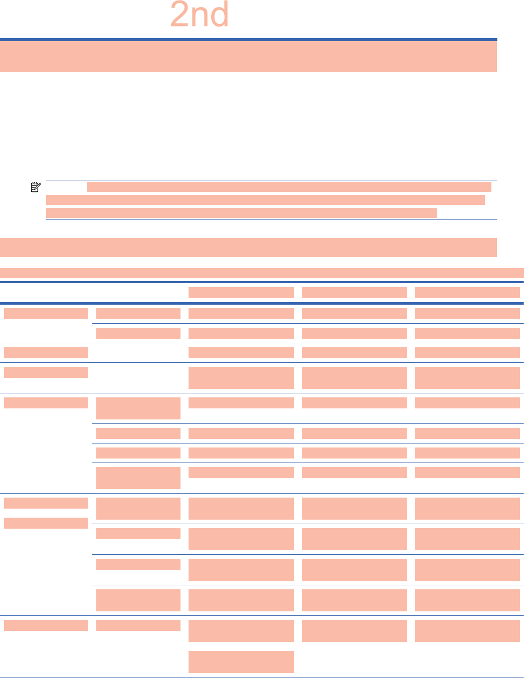
B Technical specifications
NOTE: All performance specifications are provided by the component manufacturers. Performance
specifications represent the highest specification of all HP's component manufacturers' typical level
specifications for performance and actual performance might vary either higher or lower.
HP Digital Signage Display
Table B-1 Specifications
HP LD4201 HP LD4210 HP LD4710
Display Size 106.73 cm (42 in) 106.73 cm (42 in) 119.28 cm (47 in)
Type TFT LCD panel TFT LCD panel TFT LCD panel
Viewable image size 106.73 cm (42 in) diagonal 106.73 cm (42 in) diagonal 119.28 cm (47 in) diagonal
Pixel pitch 0.4845 x 0.4845 mm
(0.0191 x 0.0191 in) X RGB
0.4845 x 0.4845 mm
(0.0191 x 0.0191 in) X RGB
0.5415 x 0.5415 mm
(0.0213 x 0.0213 in) X RGB
Weight—maximum Without stand and
speaker
18.6 kg (41.01 lbs) 18.6 kg (41.01 lbs) 22.7 kg (50.05 lbs)
With speaker 19.3 kg (42.55 lbs) 19.3 kg (42.55 lbs) 23.4 kg (51.59 lbs)
With stand 21.9 kg (48.28 lbs) 21.9 kg (48.28 lbs) 26.0 kg (57.32 lbs)
With stand and
speaker
22.6 kg (49.82 lbs) 22.6 kg (49.82 lbs) 26.7 kg (58.86 lbs)
Dimensions
(W x H x D)
Without stand and
speaker
96.71 x 55.98 x 12.37 cm
(38.07 x 22.04 x 4.87 in)
96.71 x 55.98 x 12.37 cm
(38.07 x 22.04 x 4.87 in)
107.95 x 62.46 x 12.29 cm
(42.50 x 24.59 x 4.84 in)
With speaker 96.71 x 55.98 x 12.37 cm
(38.07 x 22.04 x 4.87 in)
96.71 x 55.98 x 12.37 cm
(38.07 x 22.04 x 4.87 in)
107.95 x 62.46 x 12.29 cm
(42.50 x 24.59 x 4.84 in)
With stand 96.71 x 63.50 x 25.86 cm
(38.07 x 25 x 10.18 in)
96.71 x 63.50 x 25.86 cm
(38.07 x 25 x 10.18 in)
107.95 x 69.77 x 29.83 cm
(42.50 x 27.47 x 11.7 in)
With stand and
speaker
96.71 x 63.50 x 25.86 cm
(38.07 x 25 x 10.18 in)
96.71 x 63.50 x 25.86 cm
(38.07 x 25 x 10.18 in)
107.95 x 69.77 x 29.83 cm
(42.50 x 27.47 x 11.7 in)
Power Rated voltage AC 100-240
V~50/60 Hz 2.2 A
Japan:
AC 100 V~50/60 Hz 2.2 A
AC 100-240
V~50/60 Hz 2.2 A
Japan:
AC 100 V~50/60 Hz 2.2 A
AC 100-240
V~50/60 Hz 2.2 A
Japan:
AC 100 V~50/60 Hz 2.2 A
ENWW HP Digital Signage Display 85
D
r
af
t
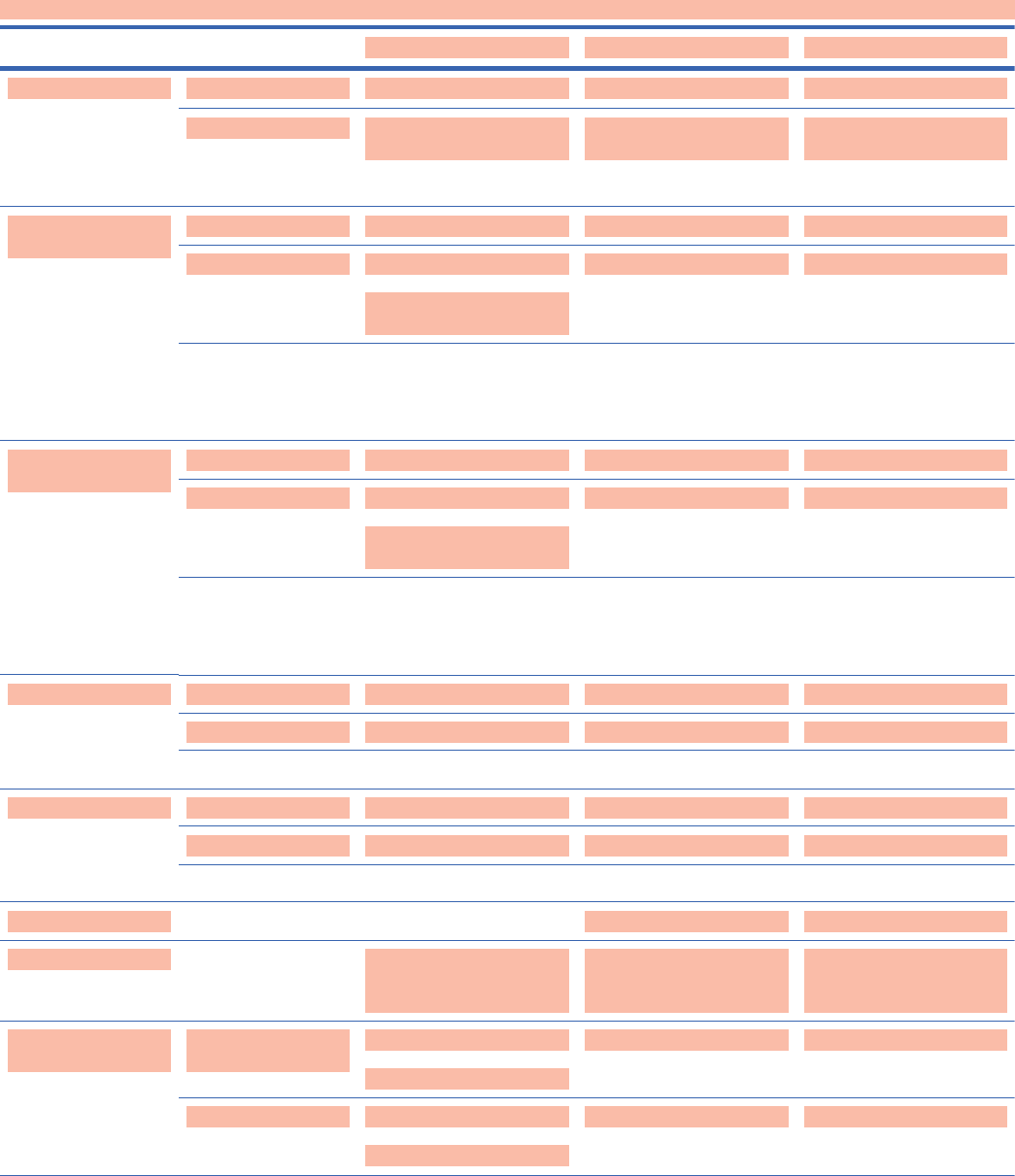
Table B-1 Specifications (continued)
HP LD4201 HP LD4210 HP LD4710
Power consumption On mode 220 W Typical 220 W Typical 270 W Typical
Sleep mode 1 W (RGB) / 2 W (HDMI/
DVI)
1 W (RGB) / 2 W (HDMI/
DVI)
(if LAN OFF is selected)
1 W (RGB) / 2 W (HDMI/
DVI)
(if LAN OFF is selected)
Resolution—
maximum
RGB 1920 x 1080 @ 60 Hz 1920 x 1080 @ 60 Hz 1920 x 1080 @ 60 Hz
HDMI/DVI 1920 x 1080 @ 60 Hz
(if supported by OS or video
card type)
1920 x 1080 @ 60 Hz
(if supported by OS or video
card type)
1920 x 10800 @ 60 Hz
(if supported by OS or video
card type)
DisplayPort 1920 x 1080 @ 60 Hz
(if supported by OS or video
card type)
1920 x 1080 @ 60 Hz
(if supported by OS or video
card type)
1920 x 1080 @ 60 Hz
(if supported by OS or video
card type)
Resolution—
recommended
RGB 1920 x 1080 @ 60 Hz 1920 x 1080 @ 60 Hz 1920 x 1080 @ 60 Hz
HDMI/DVI 1920 x 1080 @ 60 Hz
(if supported by OS or video
card type)
1920 x 1080 @ 60 Hz
(if supported by OS or video
card type)
1920 x 1080 @ 60 Hz
(if supported by OS or video
card type)
DisplayPort 1920 x 1080 @ 60 Hz
(if supported by OS or video
card type)
1920 x 1080 @ 60 Hz
(if supported by OS or video
card type)
1920 x 1080 @ 60 Hz
(if supported by OS or video
card type)
Horizontal frequency RGB 30–83 kHz 30–83 kHz 30–83 kHz
HDMI/DVI 30–83 kHz 30–83 kHz 30–83 kHz
DisplayPort 30–83 kHz 30–83 kHz 30–83 kHz
Vertical frequency RGB 56–75 Hz 56–75 Hz 56–75 Hz
HDMI/DVI 56–60 Hz 56–60 Hz 56–60 Hz
DisplayPort 56–60 Hz 56–60 Hz 56–60 Hz
Synchronization type Composite/Separate/Digital Composite/Separate/Digital Composite/Separate/Digital
Input connector 15-pin D-Sub type, HDMI/DVI
(digital), RS-232C,
DisplayPort, USB
15-pin D-Sub type, HDMI/DVI
(digital), RS-232C,
DisplayPort, USB, LAN
15-pin D-Sub type, HDMI/
DVI (digital), RS-232C,
DisplayPort, USB, LAN
Environmental
conditions
Operating
temperature
0° to 40°C
Humidity 10% to 80%
0° to 40°C
Humidity 10% to 80%
0° to 40°C
Humidity 10% to 80%
Storage temperature –20° to 60°C
Humidity 20% to 80%
–20° to 60°C
Humidity 20% to 80%
–20° to 60°C
Humidity 20% to 80%
86 Appendix B Technical specifications ENWW
2
n
d
D
r
af
t

Table B-1 Specifications (continued)
HP LD4201 HP LD4210 HP LD4710
Audio (select models) RMS audio output 10 W + 10 W (R + L) 10 W + 10 W (R + L) 10 W + 10 W (R + L)
Input sensitivity 0.7 Vrms 0.7 Vrms 0.7 Vrms
Speaker impedance 8 Ohms 8 Ohms 8 Ohms
ENWW HP Digital Signage Display 87
2
n
d
D
r
af
t
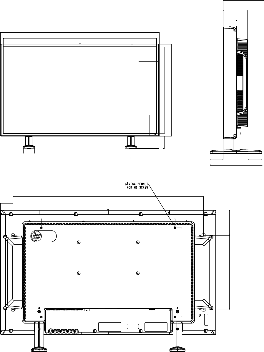
HP LD4201 and HP LD4210 dimensions
Figure B-1 HP LD4201 and HP LD4210—Front and side view
967 mm
(38 in) 933.2 mm
(36.74 in)
16.9 mm
(.66 in)
526 mm
(20.7 in)
559.8 mm
(22.03 in)
16.9 mm
(.66 in)
16.9 mm
(.66 in)
620.5 mm
(24.43 in)
69.6 mm
(2.74in)
75.2 mm
(2.96 in)
123.7 mm
(4.87 in)
121 mm
(4.76 in)
258.61 mm
(10.18 in)
67.4 mm
(2.65 in)
64.5 mm
(2.54 in)
70.41 mm
(2.77 in)
Figure B-2 HP LD4201 and HP LD4210—Back view
855.1 mm
(33.66 in)
600 mm (23.62 in)
400 mm
(15.75 in)
332 mm
(13.07 in)
113.9 mm
(4.48 in)
56 mm
(2.2 in)
88 Appendix B Technical specifications ENWW
2
n
d
D
r
af
t
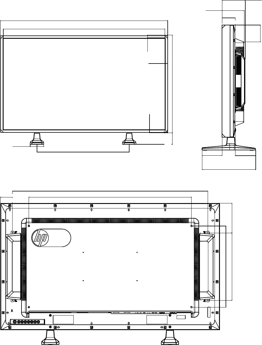
HP LD4710 dimensions
Figure B-3 HP LD4710—Front and side view
1079.5 mm
(42.5 in) 1043.7 mm
(41.09 in)
588.7 mm
(23.18 in)
86.9 mm
(3.42 in)
17.9 mm
(.70 in)
17.9 mm
(.70 in)
624.6 mm
(24.59 in)
17.9 mm
(.70 in)
73.1 mm
(2.88 in)
129.2 mm
(5.09 in)
122.9 mm
(4.84 in)
94.3 mm
(3.71 in)
111 mm
(4.37 in)
114.4 mm
(4.50 in)
298.3 mm
(11. 74 i n )
72.9 mm
(2.87 in)
Figure B-4 HP LD4710—Back view
58.7 mm
(2.31 in)
962 mm
(37.87 in) 800 mm
(31.50 in)
146.3 mm
(5.76 in)
332 mm
(13.07 in)
400 mm
(15.75 in)
ENWW HP LD4710 dimensions 89
2
n
d
D
r
af
t

Recognizing preset display resolutions
The display resolutions listed below are the most commonly used modes and are set as factory
defaults. This display automatically recognizes these preset modes and they will appear properly
sized and centered on the screen.
Preset display modes
Table B-2 Factory preset display modes
Preset Pixel format Horizontal frequency (kHz) Vertical Frequency (Hz)
1640 x 350 31.469 70.8
2720 x 400 31.468 70.8
*3 640 x 480 31.469 59.94
4640 x 480 37.5 75
*5 800 x 600 37.879 60.317
6800 x 600 46.875 75
7832 x 624 49.725 74.55
*8 1024 x 768 48.363 60
91024 x 768 60.123 75.029
*10 1280 x 720 44.772 59.855
*11 1280 x 768 47.7 60
*12 1360 x 768 47.72 59.799
*13 1360 x 768 47.7 60
*14 1280 x 1024 63.981 60.02
15 1280 x 1024 79.98 75.02
*16 1680 x 1050 65.290 59.954
*17 1920 x 1080 67.5 60
1 to 17 RGB mode
* HDMI/DVI mode
DTV mode
HDMI/DVI (DTV) DisplayPort
480i x x
480p o o
576i x x
90 Appendix B Technical specifications ENWW
D
r
af
t
HDMI/DVI (DTV) DisplayPort
576p o o
720p o o
1080i o o
1080p o o
NOTE: DTV/PC selection on HDMI/DVI inputs is available for media player/computer resolutions—
640 x 480/60 Hz, 1280 x 720/60 Hz, 1920 x 1080/60 Hz and DTV resolutions—480p, 720p, 1080p.
Power indicator
Mode LED indicator light
On Mode Blue
Sleep Mode Amber
Off Mode -
ENWW Recognizing preset display resolutions 91
2
n
d
D
r
af
t
92 Appendix B Technical specifications ENWW
2
n
d
D
r
af
t
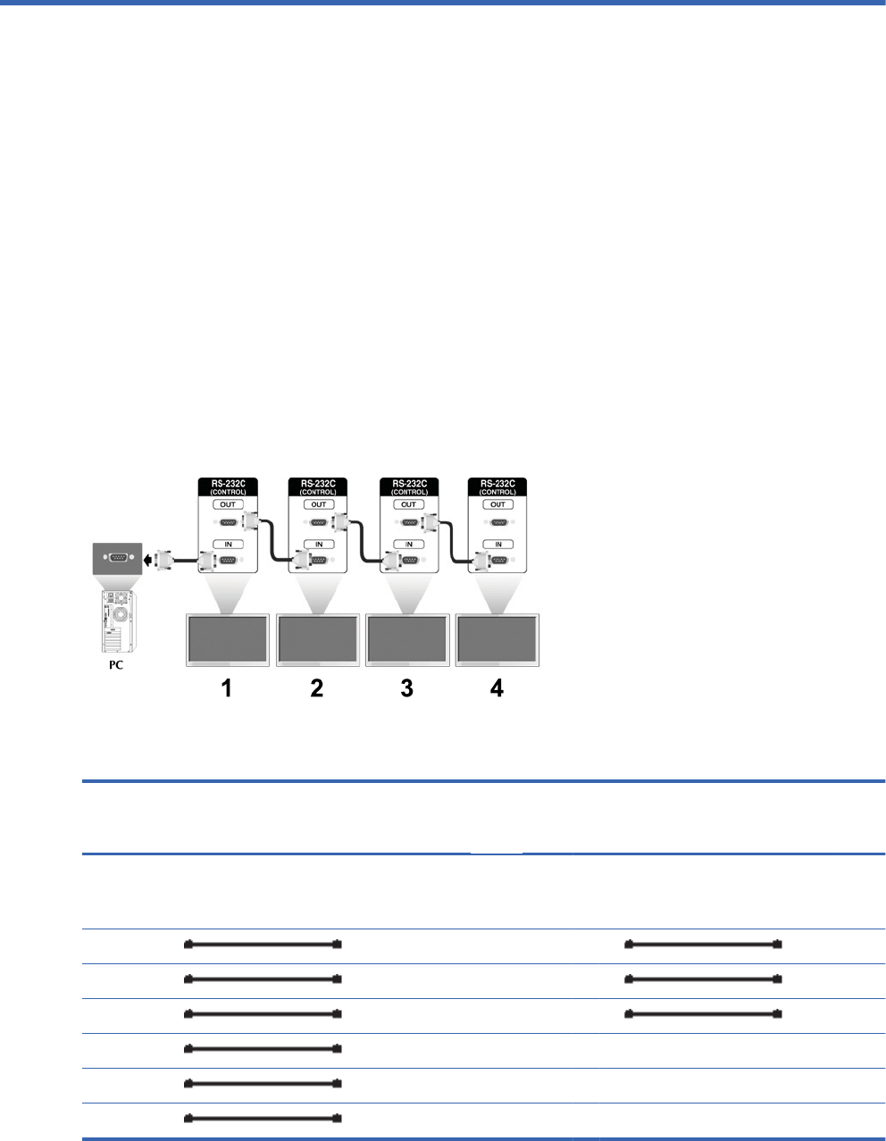
C Command reference
Use this method to connect several displays to a single media player/computer. You can control
several displays at a time by connecting them to a single media player/computer.
Connecting the cable
Connect the RS-232-C cable as shown in the following illustration. The RS-232-C protocol is used for
communication between the media player/computer and the display. You can turn the display on/off,
select an input source or adjust the OSD menu from the media player/computer.
RS-232-C configurations
7-Wire configurations
(Standard RS-232-C cable)
3-Wire configurations
(Not Standard)
media
player/
computer
Display media
player/
computer
Display
RXD 2 3TXD RXD2 3TXD
TXD 3 2RXD TXD3 2RXD
GND 5 5GND GND5 5GND
DTR 4 6DSR DTR4 6DSR
DSR 6 4DTR DSR6 4DTR
RTS 7 8CTS RTS7 7CTS
ENWW Connecting the cable 93
2
n
d
D
r
af
t
7-Wire configurations
(Standard RS-232-C cable)
3-Wire configurations
(Not Standard)
CTS 8 7RTS CTS8 8RTS
D-Sub 9
(Female)
D-Sub 9
(Female)
D-Sub 9
(Female)
D-Sub 9
(Female)
Communication parameter
łBaud Rate—9600 baud Rate (UART)
łData Length—8 bit
łParity Bit—None
łStop Bit—1 bit
łFlow Control—None
łCommunication Code—ASCII code
łUse a crossed (reverse) cable
Command reference list
COMMAND1 COMMAND2 DATA1 DATA2 DATA3
01. Power k a 00H–01H
02. Input Select k b 07H–0BH
03. Aspect Ratio k c 01H–1FH
04. Screen Mute k d 00H–01H
05. Volume Mute k e 00H–01H
06. Volume Control k f 00H–64H
07. Contrast k g 00H–64H
08. Brightness k h 00H–64H
09. Color k i 00H–64H
10. Tint k j 00H–64H
11. Sharpness k k 00H–64H
12. OSD Select k l 00H–01H
13. Remote Lock/Key Lock k m 00H–01H
14. Balance k t 00H–64H
15. Color Temperature k u 00H–02H
94 Appendix C Command reference ENWW
2
n
d
D
r
af
t
COMMAND1 COMMAND2 DATA1 DATA2 DATA3
16. Abnormal State k z FFH
17. ISM Mode j p 01H–08H
18. Auto Configuration j u 01H
19. Key m c Key Code
20. Tile Mode d d 00H–55H
21. Tile H Position d e 00H–14H
22. Tile V Position d f 00H–14H
23. Tile H Size d g 00H–64H
24. Tile V Size d h 00H–64H
25. Tile ID Set d i 00H–19H
26. Natural Mode (In Tile Mode) d j 00H–01H
27. Picture Mode (PSM) d x 00H–06H
28. Sound Mode d y 01H–05H
29. Fan Fault Check d w FFH
30. Elapsed Time Return d l FFH
31. Temperature Value d n FFH
32. Lamp Fault Check d p FFH
33. Auto Volume d u 00H–01H
34. Speaker d v 00H–01H
35. Time f a 00H–06H 00H–17H 00H–3BH
36. On Timer (On/Off Timer) Time f dF1H–F4H
E0H–E4H
01H–80H
00H–17H 00H–3BH
37. Off Timer (On/Off Timer) Time f eF1H–F4H
E0H–E4H
01H–80H
00H–17H 00H–3BH
38. Scheduling Input Select f u F1H–F4H 07H–0BH
39. Sleep Time f f 00H–08H
40. Auto Sleep f g 00H–01H
41. Power On Delay f h 00H–64H
42. Language f i 00H–09H
43. DPM Select f j 00H–01H
ENWW Command reference list 95
2
n
d
D
r
af
t
COMMAND1 COMMAND2 DATA1 DATA2 DATA3
44. Reset f k 00H–02H
45. Power Saving f l 00H–03H
46. Power Indicator f o 00H–01H
47. Serial No. f y FFH
48. S/W Verison f z FFH
49. Input Select x b 60H–C0H
Transmission/Receiving Protocol
Transmission
[Command1][Command2][][Set ID][][Data][Cr]
[Command 1] First command (k, j, m, d, f, x)
[Command 2] Second command (a to u)
[Set ID] Set up the Set ID number of product. range : 01H to 63H. by setting
'0', server can control all products.
In case of operating with more than 2 sets using set ID as '0' at the
same time, it should not be checked the ack message. Because all
sets will send the ack message, so it's impossible the check the
whole ack messages.
[Data] To transmit command data.
Transmit 'FF' data to read status of command.
[Cr] Carriage Return
ASCII code '0 x 0 D'
[] ASCII code Space (0 x 20)
OK Acknowledgement
[Command2][][Set ID][][OK][Data][x]
*The Product transmits ACK (acknowledgement) based on this format when receiving normal data. At
this time, if the data is in data read mode, it indicates present status data. If the data is in data write
mode, it returns the data of the media player/computer.
Error Acknowledgement
96 Appendix C Command reference ENWW
2
n
d
D
r
af
t

[Command2][][Set ID][][NG][Data][x]
*If there is error, it returns NG
01. Power (Command : a)
To control Power On/Off of the Set.
Transmission
[k][a][][Set ID][][Data][Cr]
[Data] 0 : Power Off
1 : Power On
Acknowledgement
[a][][Set ID][][OK][Data][x]
To show the status of Power On/Off.
Transmission
[k][a][][Set ID][][FF][Cr]
Acknowledgement
[a][][Set ID][][OK][Data][x]
[Data] 0 : Power Off
1 : Power On
02. Input Select (Command : b) (Main Picture Input)
To select input source for the Set.
You can also select an input source using the INPUT button on the remote control.
Transmission
ENWW Transmission/Receiving Protocol 97
2
n
d
D
r
aft

[k][b][][Set ID][][Data][Cr]
[Data] 7 : RGB (PC)
8 : HDMI (DTV)
9 : HDMI (PC)
A: Display port (DTV)
B: Display port (PC)
Acknowledgement
[b][][Set ID][][OK][Data][x]
[Data] 7 : RGB (PC)
8 : HDMI (DTV)
9 : HDMI (PC)
A: Display port (DTV)
B: Display port (PC)
03. Aspect Ratio (Command : c) (Main picture format)
To adjust the screen format.
You can also adjust the screen format using the ARC (Aspect Ratio Control) button on remote control
or in the Screen menu.
Transmission
[k][c][][Set ID][][Data][Cr]
98 Appendix C Command reference ENWW
D
r
af
t

[Data] 1 : Normal Screen (4:3)
2 : Wide Screen (16:9)
4 : Zoom (HDMI-PC, Display Port-PC)
6 : Original
7 : 14:9 (HDMI-PC, Display Port-PC)
9 : Just Scan (HD-DTV)
*When the RGB, HDMI/DVI-PC, DisplayPort-PC
mode (1:1)
10 to 1F : Cinema Zoom 1 to 16 (HD-DTV)
Acknowledgement
[c][][Set ID][][OK][Data][x]
04. Screen Mute (Command : d)
To select screen mute on/off.
Transmission
[k][d][][Set ID][][Data][Cr]
[Data] 0 : Screen mute off (Picture on)
1 : Screen mute on (Picture off)
Acknowledgement
[d][][Set ID][][OK][Data][x]
05. Volume Mute (Command : e)
To control On/Off of the Volume Mute.
Transmission
[k][e][][Set ID][][Data][Cr]
ENWW Transmission/Receiving Protocol 99
2
n
d
D
r
af
t

[Data] 0 : Volume Mute On (Volume Off)
1 : Volume Mute Off (Volume On)
Acknowledgement
[e][][Set ID][][OK][Data][x]
[Data] 0 : Volume Mute On (Volume Off)
1 : Volume Mute Off (Volume On)
06. Volume Control (Command : f)
To adjust Volume.
Transmission
[k][f][][Set ID][][Data][Cr]
[Data] Min : 00H to Max : 64H
(Hexadecimal code)
Acknowledgement
[f][][Set ID][][OK][Data][x]
[Data] Min : 00H to Max : 64H
100 Appendix C Command reference ENWW
2
n
d
D
r
af
t

Real data mapping 0 : Step 0
:
A : Step 10
:
F : Step 15
10 : Step 16
:
64 : Step 100
07. Contrast (Command : g)
To adjust screen contrast. You can also adjust the contrast in the Picture menu.
Transmission
[k][g][][Set ID][][Data][Cr]
[Data] Min : 00H to Max : 64H
Acknowledgement
[g][][Set ID][][OK][Data][x]
Real data mapping 0 : Step 0
:
A : Step 10
:
F : Step 15
10 : Step 16
:
64 : Step 100
08. Brightness (Command : h)
To adjust screen brightness. You can also adjust the brightness in the Picture menu.
ENWW Transmission/Receiving Protocol 101
2
n
d
D
r
aft

Transmission
[k][h][][Set ID][][Data][Cr]
[Data] Min : 00H to Max : 64H
Refer to “Real data mapping” as shown below.
Acknowledgement
[h][][Set ID][][OK][Data][x]
Real data mapping 0 : Step 0
:
A : Step 10
:
F : Step 15
10 : Step 16
:
64 : Step 100
09. Color (Command : i) (Video Timing only)
To adjust the screen color. You can also adjust the color in the Picture menu.
Transmission
[k][i][][Set ID][][Data][Cr]
[Data] Min : 00H to Max : 64H
(Hexadecimal code)
102 Appendix C Command reference ENWW
2
n
d
D
r
af
t

Real data mapping 0 : Step 0
:
A : Step 10
:
F : Step 15
10 : Step 16
:
64 : Step 100
Acknowledgement
[i][][Set ID][][OK][Data][x]
[Data] Min : 00H to Max : 64H
(Hexadecimal code)
10. Tint (Command : j) (Video Timing only)
To adjust the screen tint. You can also adjust the tint in the Picture menu.
Transmission
[k][j][][Set ID][][Data][Cr]
[Data] Red: 00H to Green: 64H
(Hexadecimal code)
ENWW Transmission/Receiving Protocol 103
2
n
d
D
r
af
t

Real data mapping 0 : Step 0
:
A : Step 10
:
F : Step 15
10 : Step 16
:
64 : Step 100
Acknowledgement
[j][][Set ID][][OK][Data][x]
[Data] Red: 00H to Green: 64H
Tint real data mapping 0 : Step 0 to Red
:
64 : Step 100 to Green
11. Sharpness (Command : k) (Video Timing only)
To adjust the screen Sharpness. You can also adjust the sharpness in the Picture menu.
Transmission
[k][k][][Set ID][][Data][Cr]
[Data] Min : 00H to Max : 64H
(Hexadecimal code)
104 Appendix C Command reference ENWW
2
n
d
D
r
af
t

Real data mapping 0 : Step 0
:
A : Step 10
:
F : Step 15
10 : Step 16
:
64 : Step 100
Acknowledgement
[k][][Set ID][][OK][Data][x]
[Data] Min : 00H to Max : 64H
12. OSD Select (Command : l)
To control OSD on/off to the set.
Transmission
[k][l][][Set ID][][Data][Cr]
[Data] 0 : OSD Off
1 : OSD On
Acknowledgement
[l][][Set ID][][OK][Data][x]
[Data] 0 : OSD Off
1 : OSD On
ENWW Transmission/Receiving Protocol 105
2
n
d
D
r
af
t

13. Remote Lock /Key Lock (Command : m)
To control Remote Lock on/off to the set.
This function, when controlling RS-232C, locks the remote control and the local keys.
Transmission
[k][m][][Set ID][][Data][Cr]
[Data] 0 : Off
1 : On
Acknowledgement
[m][][Set ID][][OK][Data][x]
[Data] 0 : Off
1 : On
14. Balance (Command : t)
To adjust the sound balance.
Transmission
[k][t][][Set ID][][Data][Cr]
[Data] Min : 00H to Max : 64H
(Hexadecimal code)
00H : Step L50
64H : Step R50
Acknowledgement
[t][][Set ID][][OK][Data][x]
106 Appendix C Command reference ENWW
2
n
d
D
r
af
t

[Data] Min : 00H to Max : 64H
00H : Step 0 to L50
64H : Step 100 to R50
Balance : L50 to R50
15. Color Temperature (Command : u)
To adjust the screen color temperature.
Transmission
[k][u][][Set ID][][Data][Cr]
[Data] 0 : Medium
1 : Cool
2 : Warm
Acknowledgement
[u][][Set ID][][OK][Data][x]
[Data] 0 : Medium
1 : Cool
2 : Warm
16. Abnormal state (Command : z)
Abnormal State : Used to Read the power off status when Stand-by mode.
Transmission
[k][z][][Set ID][][Data][Cr]
[Data] FF : Read
Acknowledgement
ENWW Transmission/Receiving Protocol 107
2
n
d
D
r
aft

[z][][Set ID][][OK][Data][x]
[Data] 0 : Normal (Power on and signal exist)
1 : No signal (Power on)
2 : Turn the display off by remote control
3 : Turn the display off by sleep time function
4 : Turn the display off by RS-232-C function
8 : Turn the display off by off time function
9 : Turn the display off by auto off function
17. ISM mode (Command : j p)
Used to select the afterimage preventing function.
Transmission
[j][p][][Set ID][][Data][Cr]
[Data] 1H : Inversion
2H : Orbiter
4H : White Wash
8H : Normal
Acknowledgement
[p][][Set ID][][OK][Data][x]
18. Auto Configure (Command : j u)
To adjust picture position and minimize image shaking automatically. It works only in RGB (PC)
mode.
Transmission
[j][u][][Set ID][][Data][Cr]
108 Appendix C Command reference ENWW
2
n
d
D
r
af
t

[Data] 1 : To set
Acknowledgement
[u][][Set ID][][OK][Data][x]
19. Key (Command : m c)
To send IR remote key code.
Transmission
[m][c][][Set ID][][Data][Cr]
Data Key code : Refer to the IR Codes Table on page 128 section.
Acknowledgement
[c][][Set ID][][OK][Data][x]
20. Tile Mode (Command : d d)
Change a Tile Mode.
Transmission
[d][d][][Set ID][][Data][x]
[Data] Description
00 or 11 Tile mode is off.
12 1 x 2 mode (column x row)
13 1 x 3 mode
14 1 x 4 mode
... ...
55 5 x 5 mode
*The data cannot be set to 0X or X0 except 00.
Acknowledgement
ENWW Transmission/Receiving Protocol 109
D
r
aft

[d][][00][][OK/NG][Data][x]
21. Tile H Position (Command : d e)
To set the Horizontal position.
Transmission
[d][e][][Set ID][][Data][x]
[Data] Min : 00H to Max : 14H
00H : Step -10 (Left)
14H : Step 10 (Right)
Acknowledgement
[e][][Set ID][][OK/NG][Data][x]
22. Tile V Position (Command : d f)
To set the Vertical position.
Transmission
[d][f][][Set ID][][Data][x]
[Data] Min : 00H to Max : 14H
00H : Step -10 (Left)
14H : Step 10 (Right)
Acknowledgement
[f][][Set ID][][OK/NG][Data][x]
23. Tile H Size (Command : d g)
To set the Horizontal size.
110 Appendix C Command reference ENWW
2
n
d
D
r
aft

Transmission
[d][g][][Set ID][][Data][x]
[Data] Min : 00H to Max : 64H
Real data mapping 0 : Step 0
:
A : Step 10
:
F : Step 15
10 : Step 16
:
64 : Step 100
Acknowledgement
[g][][Set ID][][OK/NG][Data][x]
24. Tile V Size (Command : d h)
To set the Vertical size.
Transmission
[d][h][][Set ID][][Data][x]
[Data] Min : 00H to Max : 64H
ENWW Transmission/Receiving Protocol 111
2
n
d
D
r
af
t

Real data mapping 0 : Step 0
:
A : Step 10
:
F : Step 15
10 : Step 16
:
64 : Step 100
Acknowledgement
[h][][Set ID][][OK/NG][Data][x]
25. Tile ID Set (Command : d i)
To assign the Tile ID for Tiling function.
Transmission
[d][i][][Set ID][][Data][x]
[Data] Min : 00H to Max : 19H
(Hexadecimal code)
Acknowledgement
[i][][Set ID][][OK/NG][Data][x]
26. Natural Mode (In Tile Mode) (Command : d j)
To assign the Title Natural mode for Tiling function.
Transmission
[d][j][][Set ID][][Data][x]
112 Appendix C Command reference ENWW
2
n
d
D
r
af
t

[Data] 0 : Natural Off
1 : Natural On
ff : Read Status
Acknowledgement
[j][][Set ID][][OK/NG][Data][x]
27. Picture Mode (Command : d x)
To adjust the picture mode.
Transmission
[d][x][][Set ID][][Data][x]
Data Structure
Data (Hex) MODE
00 Vivid
01 Standard
02 Cinema
03 Sport
04 Game
05 Expert 1
06 Expert 2
Acknowledgement
[x][][Set ID][][OK/NG][Data][x]
28. Sound Mode (Command : d y )
To adjust the Sound mode.
Transmission
[d][y][][Set ID][][Data][X]
ENWW Transmission/Receiving Protocol 113
2
n
d
D
r
af
t

Data Structure
Data (Hex) MODE
01 Standard
02 Music
03 Cinema
04 Sport
05 Game
Acknowledgement
[y][][Set ID][][OK/NG][Data][x]
29. Fan Fault check (Command : d w )
To check the Fan fault of the TV.
Transmission
[d][w][][Set ID][][Data][x]
[Data] Data is always FF (in Hex)
Data ff: Read Status
Acknowledgement
[w][][Set ID][][OK/NG][Data][x]
[Data] * Data is the status value of the Fan fault.
0: Fan fault
1: Fan OK
2: N/A (Not Avaliable)
30. Elapsed time return (Command : d l)
To read the elapsed time.
114 Appendix C Command reference ENWW
2
n
d
D
r
aft

Transmission
[d][l][][Set ID][][Data][x]
[Data] Data is always FF (in Hex)
Acknowledgement
[l][][Set ID][][OK/NG][Data][x]
[Data] The data means used hours.
(Hexadecimal code)
31. Temperature value (Command : d n)
To read the inside temperature value.
Transmission
[d][n][][Set ID][][Data][x]
[Data] Data is always FF (in Hex)
Acknowledgement
[n][][Set ID][][OK/NG][Data][x]
[Data] The data is 1 byte long in Hexadecimal.
32. Lamp fault Check (Command : d p)
To check lamp fault.
Transmission
[d][p][][Set ID][][Data][x]
ENWW Transmission/Receiving Protocol 115
2
n
d
D
r
af
t

[Data] Data is always FF (in Hex)
Acknowledgement
[p][][Set ID][][OK/NG][Data][x]
[Data] 0 : Lamp Fault
1 : Lamp OK
2 : N/A(DPM/Power Off)
33. Auto volume (Command : d u)
Automatically adjust the volume level.
Transmission
[d][u][][Set ID][][Data][x]
[Data] 0 : Off
1 : On
Acknowledgement
[u][][Set ID][][OK/NG][Data][x]
34. Speaker (Command : d v)
Turn the speaker on or off.
Transmission
[d][v][][Set ID][][Data][x]
[Data] 0 : Off
1 : On
Acknowledgement
116 Appendix C Command reference ENWW
2
n
d
D
r
aft

[v][][Set ID][][OK/NG][Data][x]
35. Time (Command : f a)
Set the current time.
Transmission
[f][a][][Set ID][][Data1][][Data2][][Data3][Cr]
[Data1] 0 : Monday
1 : Tuesday
2 : Wednesday
3 : Thursday
4 : Friday
5 : Saturday
6 : Sunday
[Data2] 0H to 17H (Hours)
[Data3] 00H to 3BH (Minutes)
Acknowledgement
[a][][Set ID][][OK/NG][Data1][Data2][Data3][x]
*When reading data, FFH is inputted for [Data1], [Data2] and [Data3]. In other cases, all are treated
as NG.
36. On Timer (On/Off Timer) Time (Command : f d)
Set On Timer.
Transmission
[f][d][][Set ID][][Data1][][Data2][][Data3][Cr]
ENWW Transmission/Receiving Protocol 117
2
n
d
D
r
af
t

1. 2. 3.
[Data1] f1h to f4h (read one index) e0htoe4h (delete one index),
e0h (delete all indexes)
01h to 80h (write) (Day of Week)
f1: read 1st index of On Time
List
e0: delete all indexes of On Time
List
bit0 (01h) : Monday
f2: read 2nd index of On Time
List
e1: delete 1st index of On Time
List
bit1 (02h) : Tuesday
f3: read 3rd index of On Time
List
e2: delete 2nd index of On Time
List
bit2 (04h) : Wednesday
f4: read 4th index of On Time
List
e3: delete 3rd index of On Time
List
bit3 (08h) : Thursday
bit4 (10h) : Friday
e4: delete 4th index of On Time
List
bit5 (20h) : Saturday
bit6 (40h) : Sunday
bit7 (80h) : Everyday
(1fh) : Monday to Friday
(3fh) : Monday to Saturday
(60h) : Saturday to Sunday
[Data2] 00h to 17h, ffh (Hours)
[Data3] 00h to 3bh, ffh (Minutes)
*When you read/delete the current on time list, all of [Data2][Data3] have to be
0xff.
ex1: fd 01 f1 ff ff - when you read 1st index of On Time List
ex2: fd 01 e1 ff ff - when you delete 1st index of On Time List
ex3: fd 01 3f 02 03 - when you write one On Time Data, "Monday to Saturday,
02:03"
Acknowledgement
[d][][Set ID][][OK][Data1][Data2][Data3][x]
37. Off Timer (On/Off Timer) Time (Command : f e)
Set Off Timer.
118 Appendix C Command reference ENWW
2
n
d
D
r
aft

Transmission
[f][e][][Set ID][][Data1][][Data2][][Data3][Cr]
1. 2. 3.
[Data1] f1h to f4h (read one index) e0htoe4h(delete one index), e0h
(delete all indexes)
01h to 80h (write) (Day of Week)
f1: read 1st index of On Time
List
e0: delete all indexes of On Time
List
bit0 (01h) : Monday
f2: read 2nd index of On Time
List
e1: delete 1st index of On Time
List
bit1 (02h) : Tuesday
f3: read 3rd index of On Time
List
e2: delete 2nd index of On Time
List
bit2 (04h) : Wednesday
f4: read 4th index of On Time
List
e3: delete 3rd index of On Time
List
bit3 (08h) : Thursday
bit4 (10h) : Friday
e4: delete 4th index of On Time
List
bit5 (20h) : Saturday
bit6 (40h) : Sunday
bit7 (80h) : Everyday
(1fh) : Monday to Friday
(3fh) : Monday to Saturday
(60h) : Saturday to Sunday
[Data2] 00h to 17h, ffh (Hours)
[Data3] 00h to 3bh, ffh (Minutes)
*When you read/delete the current on time list, all of [Data2][Data3] have to be
0xff.
ex1: fd 01 f1 ff ff - when you read 1st index of On Time List
ex2: fd 01 e1 ff ff - when you delete 1st index of On Time List
ex3: fd 01 3f 02 03 - when you write one On Time Data, "Monday to Saturday,
02:03"
Acknowledgement
ENWW Transmission/Receiving Protocol 119
2
n
d
D
r
af
t

[e][][Set ID][][OK][Data1][Data2][Data3][x]
38. Scheduling Input select (Command : f u) (Main Picture Input)
To select input source for TV depending on day.
Transmission
[f][u][][Set ID][][Data1][][Data2][Cr]
1.
[Data1] f1h to f4h(write/read one index)
f1: read 1st index of On Time Input
f2: read 2nd index of On Time Input
f3: read 3rd index of On Time Input
f4: read 4th index of On Time Input
Data (Hex) INPUT
[Data2] 07 RGB-PC
08 HDMI/DVI — HD-DVD
09 HDMI/DVI—PC
A Display port (-HD-DVI)
B Display port PC)
*When you read/delete the current On Time Input, [Data2] needs to be 0xff.
ex1: fu 01 f1 ff - when you read 1st index of On Time Input
ex2: fu 01 f3 02 - when you write one On Time Input Data in to 3rd index, "AV"
Acknowledgement
[u][][Set ID][][OK][Data1][Data2][x]
120 Appendix C Command reference ENWW
2
n
d
D
r
af
t

39. Sleep Time (Command : f f)
Set Sleep Time.
Transmission
[f][f][][Set ID][][Data][Cr]
[Data] 0 : Off
1 : 10
2 : 20
3 : 30
4 : 60
5 : 90
6 : 120
7 : 180
8 : 240
Acknowledgement
[f][][Set ID][][OK/NG][Data][x]
40. Auto Sleep (Command : f g)
Set Auto Sleep.
Transmission
[f][g][][Set ID][][Data][Cr]
[Data] 0 : Off
1 : On
Acknowledgement
[g][][Set ID][][OK/NG][Data][x]
ENWW Transmission/Receiving Protocol 121
2
n
d
D
r
af
t

41. Power On Delay (Command : f h)
Set the schedule delay when the power is turned on (Unit: second).
Transmission
[f][h][][Set ID][][Data][Cr]
[Data] 00H to 64H (Data value)
Real data mapping 0 : Step 0
:
A : Step 10
:
F : Step 15
10 : Step 16
:
64 : Step 100
Acknowledgement
[h][][Set ID][][OK/NG][Data][x]
42. Language (Command : f i)
Set the OSD language.
Transmission
[f][i][][Set ID][][Data][Cr]
122 Appendix C Command reference ENWW
2
n
d
D
r
af
t

[Data] 0 : English
1 : French
2 : German
3 : Spanish
4 : Italian
5 : Portuguese
6 : Chinese
7 : Japanese
8 : Korean
9 : Russian
Acknowledgement
[i][][Set ID][][OK/NG][Data][x]
43. DPM Select (Command : f j)
Set the DPM (Display Power Management) function.
Transmission
[f][j][][Set ID][][Data][Cr]
[Data] 0 : Off
1 : On
Acknowledgement
[j][][Set ID][][OK/NG][Data][x]
44. Reset (Command : f k)
Execute the Picture, Screen and Factory Reset functions.
Transmission
[f][k][][Set ID][][Data][Cr]
ENWW Transmission/Receiving Protocol 123
D
r
af
t

[Data] 0 : Picture Reset
1 : Screen Reset
2 : Factory Reset
Acknowledgement
[k][][Set ID][][OK/NG][Data][x]
45. Power saving(Command : f I)
To set the Power saving mode.
Transmission
[f][I][][Set ID][][Data][Cr]
[Data] 0 : Off
1: (static level 1)
2: (static level 2)
3: (static level 3)
Acknowledgement
[I][][Set ID][][OK/NG][Data][x]
46. Power Indicator (Command : f o)
To set the LED for Power Indicator
Transmission
[f][o][][Set ID][][Data][Cr]
[Data] 0 : Off
1 : On
Acknowledgement
124 Appendix C Command reference ENWW
D
r
aft

[o][][Set ID][][OK/NG][Data][x]
47. Serial no. Check (Command : f y)
To read the serial numbers
Transmission
[f][y][][Set ID][][Data][Cr]
[Data] Data FF (to read the serial numbers)
Acknowledgement
[y][][Set ID][][OK/NG][Data1]to[Data13][x]
[Data] The data format is ASCII Code.
48. S/W Version (Command : f z)
Check the software version.
Transmission
[f][z][][Set ID][][Data][Cr]
[Data] FFH : Read
Acknowledgement
[z][][Set ID][][OK/NG][Data][x]
49. Input Select (Command : x b)
To select input source for the display.
Transmission
ENWW Transmission/Receiving Protocol 125
2
n
d
D
r
aft
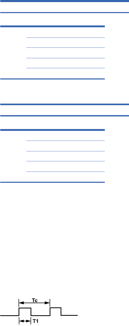
[x][b][][Set ID][][Data][Cr]
[Data] 60H : RGB (PC)
90H : HDMI/DVI (DTV)
A0H : HDMI/DVI (PC)
B0H: Display port(HD-DVD)
C0H: Display port(PC)
Acknowledgement
[b][][Set ID][][OK][Data][x]
[Data] 60H : RGB (PC)
90H : HDMI/DVI (DTV)
A0H : HDMI/DVI (PC)
B0H: Display port(HD-DVD)
C0H: Display port(PC)
IR codes
Use this method to connect your wired remote control port on the display.
Remote Control IR Code
Output waveform
łSingle pulse, modulated with 37.917kHz signal at 455kHz
łCarrier Frequency
ŃFCAR = 1/Tc=fosc/12
ŃDuty Ratio = T1/Tc = 1/3
126 Appendix C Command reference ENWW
2
n
d
D
r
af
t
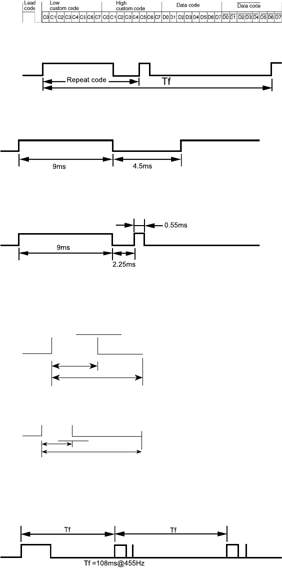
Configuration of frame
ł1st frame
łRepeat frame
Lead code
Repeat code
Bit description
łBit “0”
0.56 ms
1.12 ms
łBit “1”
0.56 ms
2.24 ms
Frame interval: Tf
The waveform is transmitted as long as a key is depressed.
ENWW IR codes 127
2
n
d
D
r
aft

IR Codes Table
Code
(Hex )
Function Note
40 Up arrow Ÿ R/C Button
41 Down arrow ź R/C Button
06 Right arrow Ź R/C Button
07 Left arrow Ż R/C Button
08 POWER ON/OFF R/C Button
C4 MONITOR ON R/C Button (Discrete IR Code)
C5 MONITOR OFF R/C Button (Discrete IR Code)
09 MUTE R/C Button
95 Energy Saving R/C Button
0B INPUT R/C Button
43 MENU R/C Button
5B EXIT R/C Button
4D PSM R/C Button
44 OK R/C Button
10 Number Key 0 R/C Button
11 Number Key 1 R/C Button
12 Number Key 2 R/C Button
13 Number Key 3 R/C Button
14 Number Key 4 R/C Button
15 Number Key 5 R/C Button
16 Number Key 6 R/C Button
17 Number Key 7 R/C Button
18 Number Key 8 R/C Button
19 Number Key 9 R/C Button
79 ARC (MARK) R/C Button (Discrete IR Code)
02 Vol+ R/C Button
03 Vol– R/C Button
E0 BrightӠ (Page UP) R/C Button
E1 BrightӠ (Page Down) R/C Button
28 BACK R/C Button
128 Appendix C Command reference ENWW
2
n
d
D
r
af
t

Code
(Hex )
Function Note
99 AUTO CONFIG R/C Button
72 ID ON (Red Color) R/C Button (Discrete IR Code)
71 ID OFF (Green Color) R/C Button
63 (Yellow Color) R/C Button
61 (Blue Color) R/C Button
7B TILE R/C Button
B0 Play Ź R/C Button
B1 Stop Ŷ R/C Button
BA Pause II R/C Button
8F Reverse ŻŻ R/C Button
8E Fast forward ŹŹ R/C Button
D5 RGB PC Discrete IR Code (Input RGB PC Selection)
C6 HDMI/DVI Discrete IR Code (Input HDMI/DVI Selection)
76 ARC (4:3) Discrete IR Code (Only 4 : 3 mode)
77 ARC (16:9) Discrete IR Code (Only 16 : 9 mode)
AF ARC (ZOOM) Discrete IR Code (Only ZOOM, Cinena ZOOM
mode)
CA USB
ENWW IR codes 129
2
n
d
D
r
af
t
130 Appendix C Command reference ENWW
2
n
d
D
r
af
t

D Agency regulatory notices
Federal Communications Commission notice
This equipment has been tested and found to comply with the limits for a Class B digital device,
pursuant to Part 15 of the FCC Rules. These limits are designed to provide reasonable protection
against harmful interference in a residential installation. This equipment generates, uses, and can
radiate radio frequency energy and, if not installed and used in accordance with the instructions, may
cause harmful interference to radio communications. However, there is no guarantee that interference
will not occur in a particular installation. If this equipment does cause harmful interference to radio or
television reception, which can be determined by turning the equipment off and on, the user is
encouraged to try to correct the interference by one or more of the following measures:
łReorient or relocate the receiving antenna.
łIncrease the separation between the equipment and the receiver.
łConnect the equipment into an outlet on a circuit different from that to which the receiver is
connected.
łConsult the dealer or an experienced radio or television technician for help.
Modifications
The FCC requires the user to be notified that any changes or modifications made to this device that
are not expressly approved by Hewlett Packard Company may void the user's authority to operate the
equipment.
Cables
Connections to this device must be made with shielded cables with metallic RFI/EMI connector hoods
to maintain compliance with FCC Rules and Regulations.
ENWW Federal Communications Commission notice 131
2
n
d
D
r
aft
Declaration of Conformity for products marked with the
FCC logo (United States only)
This device complies with Part 15 of the FCC Rules. Operation is subject to the following two
conditions:
1. This device may not cause harmful interference.
2. This device must accept any interference received, including interference that may cause
undesired operation.
For questions regarding the product, contact:
Hewlett Packard Company
P. O. Box 692000, Mail Stop 530113
Houston, Texas 77269-2000
Or, call 1-800-HP-INVENT (1-800 474-6836)
For questions regarding this FCC declaration, contact:
Hewlett Packard Company
P. O. Box 692000, Mail Stop 510101
Houston, Texas 77269-2000
Or, call (281) 514-3333
To identify this product, refer to the Part, Series, or Model number found on the product.
Canadian notice
This Class B digital apparatus meets all requirements of the Canadian Interference-Causing
Equipment Regulations.
Avis Canadien
Cet appareil numérique de la classe B respecte toutes les exigences du Règlement sur le matériel
brouilleur du Canada.
European Union regulatory notice
Products bearing the CE marking comply with the following EU Directives:
łLow Voltage Directive 2006/95/EC
łEMC Directive 2004/108/EC
łEcodesign Directive 2009/125/EC, where applicable
132 Appendix D Agency regulatory notices ENWW
2
n
d
D
r
aft
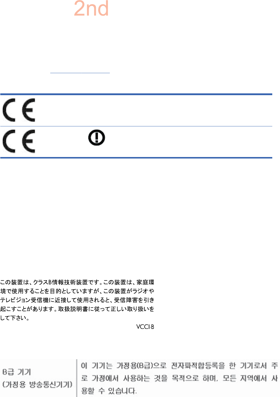
CE compliance of this product is valid if powered with the correct CE-marked AC adapter provided by
HP.
Compliance with these directives implies conformity to applicable harmonized European standards
(European Norms) that are listed in the EU Declaration of Conformity issued by HP for this product or
product family and available (in English only) either within the product documentation or at the
following web site: www.hp.eu/certificates (type the product number in the search field).
The compliance is indicated by one of the following conformity markings placed on the product:
For non-telecommunications products and for EU
harmonized telecommunications products, such
as Bluetooth® within power class below 10mW.
For EU non-harmonized telecommunications
products (If applicable, a 4-digit notified body
number is inserted between CE and !).
Please refer to the regulatory label provided on the product.
The point of contact for regulatory matters is: Hewlett-Packard GmbH, Dept./MS: HQ-TRE,
Herrenberger Strasse 140, 71034 Boeblingen, GERMANY.
German ergonomics notice
HP products which bear the “GS” approval mark, when forming part of a system comprising HP brand
computers, keyboards and monitors that bear the “GS” approval mark, meet the applicable ergonomic
requirements. The installation guides included with the products provide configuration information.
Japanese notice
Korean notice
ENWW German ergonomics notice 133
D
r
af
t

Power cord set requirements
The display power supply is provided with Automatic Line Switching (ALS). This feature allows the
display to operate on input voltages between 100–120V or 200–240V.
The power cord set (flexible cord or wall plug) received with the display meets the requirements for
use in the country where you purchased the equipment.
If you need to obtain a power cord for a different country, you should purchase a power cord that is
approved for use in that country.
The power cord must be rated for the product and for the voltage and current marked on the product's
electrical ratings label. The voltage and current rating of the cord should be greater than the voltage
and current rating marked on the product. In addition, the cross-sectional area of the wire must be a
minimum of 0.75 mm² or 18 AWG, and the length of the cord must be between 6 feet (1.8 m) and
12 feet (3.6 m). If you have questions about the type of power cord to use, contact an authorized HP
service provider.
A power cord should be routed so that it is not likely to be walked on or pinched by items placed upon
it or against it. Particular attention should be paid to the plug, electrical outlet, and the point where the
cord exits from the product.
Japanese power cord requirements
For use in Japan, use only the power cord received with this product.
CAUTION: Do not use the power cord received with this product on any other products.
Product environmental notices
Materials disposal
This HP product contains mercury in the fluorescent lamp in the display LCD that might require
special handling at end-of-life.
Disposal of this material can be regulated because of environmental considerations. For disposal or
recycling information, contact the local authorities or the Electronic Industries Alliance (EIA)
www.eiae.org.
Disposal of waste equipment by users in private households in the
European Union
This symbol on the product or on its packaging indicates that this product must not be disposed of
with your household waste. Instead, it is your responsibility to dispose of your waste equipment by
handing it over to a designated collection point for the recycling or waste electrical and electronic
equipment. The separate collection and recycling of your waste equipment at the time of disposal will
help to conserve natural resources and ensure that it is recycled in a manner that protects human
134 Appendix D Agency regulatory notices ENWW
2
n
d
D
r
aft
health and the environment. For more information about where you can drop off your waste
equipment for recycling, please contact the local city office, the household waste disposal service or
the shop where you purchased the product.
Chemical substances
HP is committed to providing our customers with information about the chemical substances in our
products as needed to comply with legal requirements such as REACH (Regulation EC
No 1907/2006 of the European Parliament and Council). A chemical information report for this
product can be found at www.hp.com/go/reach.
HP recycling program
HP encourages customers to recycle used electronic hardware, HP original print cartridges, and
rechargeable batteries. For more information about recycling programs, go to www.hp.com/recycle.
Restriction of Hazardous Substances (RoHS)
A Japanese regulatory requirement, defined by specification JIS C 0950, 2005, mandates that
manufacturers provide Material Content Declarations for certain categories of electronic products
offered for sale after July 1, 2006. To view the JIS C 0950 material declaration for this product, visit
www.hp.com/go/jisc0950.
ENWW Product environmental notices 135
2
n
d
D
r
af
t
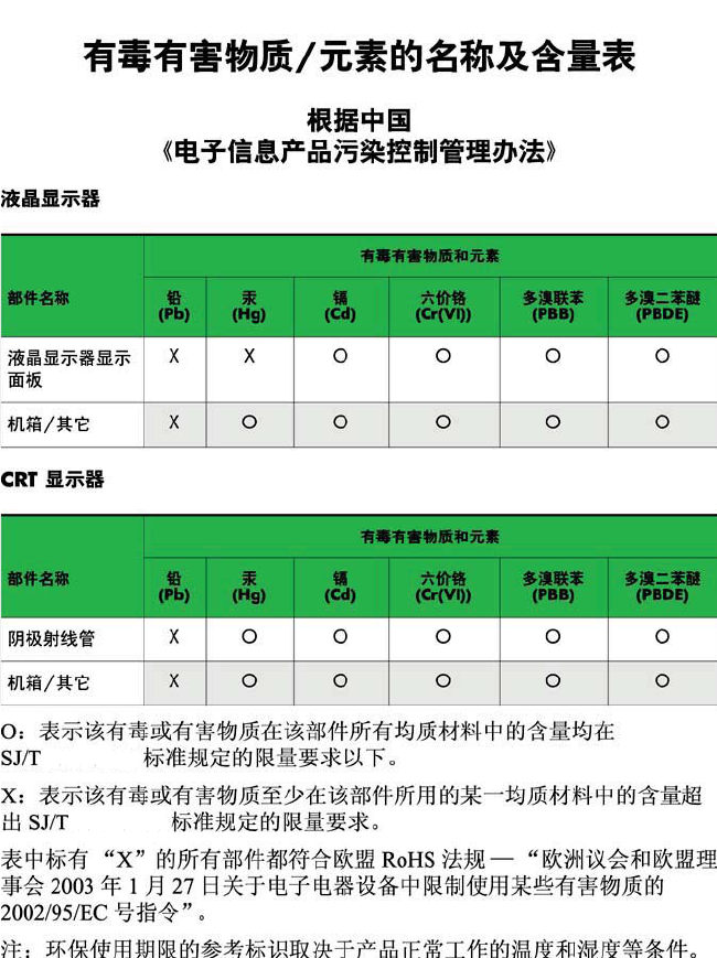
11363-2006
11363-2006
Turkey EEE regulation
In Conformity with the EEE Regulation
EEE Yönetmeli÷ine Uygundur
136 Appendix D Agency regulatory notices ENWW
2
n
d
D
r
aft
Regulatory Information cont.
FCC Compliance Statement
This equipment has been tested and found to comply
within the limits of a Class B digital device pursuant to Part
15 of the FCC Rules. These limits are designed to provide
reasonable protection against harmful interference in a
residential installation.
This equipment generates, uses, and can radiate radio
frequency energy and if not installed and used in
accordance with the instructions, may cause harmful
interference to radio communications. However, there is
no guarantee that interference will not occur in a particular
installation.
If this equipment does cause harmful interference to radio
or television reception (which can be determined by
turning the equipment on and off), the user is encouraged
to try to correct the interference by using one or more of
the following measures:
Reorient or relocate the receiving antenna.
Increase the separation between the equipment and
the receiver.
Connect the equipment into an outlet on a circuit
different from that to which the receiver is connected.
Consult the dealer or an experienced radio/TV
technician for help.
Caution: Changes or modifications not expressly approved
by the party responsible for compliance could void the
user's (or your) authority to operate the equipment. Only
peripherals (digital input/output devices, terminals, printers,
etc.) certified to comply with the Class B limits may be
attached to this monitor. Operation with non-certified
peripherals is likely to result in interference to radio and TV
reception. Only shielded signal cables may be used with
this System.
Canadian DOC Notice
This Class B digital apparatus meets all requirements of
the Canadian Interference-Causing Equipment
Regulations. Cet appareil numérique de la classe B
respecte toutes les exigences du Règlement sur le
matériel brouilleur du Canada.
CE Conformity Notice
(for Europe)
Products with the “CE” Marking comply with the EMC
Directive(89/336/EEC) and LOW VOLTAGE Directive
(73/23/EEC) issued by the Commission of the European
Community.
Compiance with these directives implies conformity to the
following European Norms :
• EN 55022 ; Radio Frequency Interference
• EN 55024 ; Electromagnetic Immunity
• EN 61000-3-2 ; Power Line Harmonics
• EN 61000-3-3 ; Voltage Fluctuations
• EN 60950-1 ; Product Safety
Low Radiation Compliance (MPR II)
This monitor meets one of the strictest guidelines available
today for low radiation emissions, offering the user extra
shielding and an antistatic screen coating. These
guidelines, set forth by a government agency in Sweden,
limit the amount of emission allowed in the Extremely Low
Frequency (ELF) and Very Low Frequency (VLF)
electromagnetic range.
01
NOTICE
The regulations are applied only to the products with the
ID LABEL indicating specific requirements.
NOTICE
The regulations are applied only to the products with the
ID LABEL indicating specific requirements.
NOTICE
The regulations are applied only to the products with the
ID LABEL indicating specific requirements.
TCO'99 (TCO'99 applied model only)
Congratulations!
You have just purchased a TCO’99 approved and labelled
product! Your choice has provided you with a product
developed for professional use. Your purchase has also
contributed to reducing the burden on the environment and
also to the further development of environmentally
adapted electronics products.

Regulatory Information cont.
02
Why do we have environmentally labelled computers?
In many countries, environmental labelling has become an
established method for encouraging the adaptation of
goods and services to the environment. With the growing
manufacture and usage of electronic equipment
throughout the world, there is a recognized concern for the
materials and substances used by electronic products
with regards to their eventual recycling and disposal. By
proper selection of these materials and substances, the
impact on the environment can be minimized.
There are also other characteristics of a computer, such as
energy consumption levels, that are important from the
viewpoints of both the work (internal) and natural (external)
environments. Electronic equipment in offices is often left
running continuously, resulting in unnecessary
consumption of large amounts of energy and additional
power generation. From the standpoint of carbon dioxide
emissions alone, it is vital to save energy.
What does labelling involve?
The product meets the requirements for the TCO’99
scheme which provides for international and environmental
labelling of personal computers and/or displays.
The labelling scheme was developed as a joint effort by the
TCO (The Swedish Confederation of Professional
Employees), Svenska Naturskyddsforeningen
(The Swedish Society for Nature Conservation) and
Statens Energimyndighet (The Swedish National
Energy Administration).
Approval requirements cover a wide range of issues:
ecology, ergonomics, emission of electrical and magnetical
fields, energy consumption and electrical safety.
Ecological criteria impose restrictions on the presence and
use of heavy metals, brominated and chlorinated flame
retardants, and other substances. The product must be
prepared for recycling and the manufacturing site(s) shall
be certified according to ISO14001 or EMAS registered.
Energy requirements include a demand that the system
unit and/or display, after a certain period of inactivity,
shall reduce its power consumption to a lower level in one
or more stages. The length of time to reactivate the system
unit shall be reasonable for the user.
Labelled products must meet strict environmental
demands, for example, in respect of the reduction of
electrical and magnetical fields as well as work load and
visual ergonomics.
Below you will find a brief summary of the ecological
requirements met by this product. The complete
ecological criteria document can be found at TCO
Development’s website http://www.tcodevelopment.com
or may be ordered from:
TCO Development
SE-114 94 STOCKHOLM, Sweden
Fax: +46 8 782 92 07
Email : development@tco.se
Information regarding TCO’99 approved and labelled
products may also be obtained at
http://www.tcodevelopment.com
Ecological requirements
Flame retardants
Flame retardants may be present in printed wiring board
laminates, cables, and housings. Their purpose is to
prevent, or at least to delay the spread of fire. Up to 30%
by weight of the plastic in a computer casing can consist of
flame retardant substances. Many flame retardants
contain bromine or chlorine, and these flame retardants
are chemically related to PCBs (polychlorinated
biphenyls). Both the flame retardants containing bromine
or chlorine and the PCBs are suspected of giving rise to
health effects, including reproductive damage in fish-
eating birds and mammals, due to the bio-accumulative*
processes when not disposed of in accordance with strict
standards for disposal.
TCO’99 requires that plastic components weighing more
than 25 grams shall not contain flame retardants with
organically bound bromine or chlorine. Flame retardants
are allowed in the printed wiring board laminates due to
the lack of commercially available alternatives.
Cadmium**
Cadmium is present in rechargeable batteries and in the
colour-generating layers of certain computer displays.
TCO’99 requires that batteries, the colour-generating
layers of display screens, and the electrical or electronics
components shall not contain any cadmium.
Mercury**
Mercury is sometimes found in batteries, relays and
switches. TCO’99 requires that batteries shall not contain
any mercury. It also demands that mercury is not present
in any of the electrical or electronics components
associated with the labelled unit. There is however one
Regulatory Information cont.
03
exception. Mercury is, for the time being, permitted in the
back light system of flat panel monitors as there today is
no commercially available alternative. TCO aims on
removing this exception when a mercury free alternative is
available.
Lead**
Lead can be found in picture tubes, display screens,
solders and capacitors. TCO’99 permits the use of lead
due to the lack of commercially available alternatives, but
in future requirements TCO Development aims at
restricting the use of lead.
_____________________________________________
* Bio-accumulative is defined as substances which
accumulate in living organisms.
**Lead, Cadmium and Mercury are heavy metals
which are bio-accumulative.
TCO’03
(TCO’03 applied model only)
Congratulations!
The display you have just purchased carries the TCO’03
Displays label.
This means that your display is designed,manufactured
and tested according to some of the strictest quality and
environmental requirements in the world. This makes for a
high performance product, designed with the user in focus
that also minimizes the impact on our natural environment.
Some of the features of the TCO’03 Display requirements:
Ergonomics
• Good visual ergonomics and image quality in order to
improve the working environment for the user and to
reduce sight and strain problems. Important
parameters are luminance, contrast, resolution,
reflectance, colour rendition and image stability.
Energy
• Energy-saving mode after a certain time – beneficial
both for the user and the environment
• Electrical safety
Emissions
• Electromagnetic fields
• Noise emissions
Ecology
• The product must be prepared for recycling and the
manufacturer must have a certified environmental
management system such as EMAS or ISO 14 001
• Restrictions on
chlorinated and brominated flame retardants and
polymers
heavy metals such as cadmium, mercury and lead.
The requirements included in this label have been
developed by TCO Development in co-operation with
scientists, experts, users as well as manufacturers all over
the world. Since the end of the 1980s TCO has been
involved in influencing the development of IT equipment in
a more user-friendly direction. Our labelling system started
with displays in 1992 and is now requested by users and
IT-manufacturers all over the world.
For more information, please visit
www.tcodevelopment.com
Information for Environmental Preservation
LGE. announced the 'LG Declaration for a Cleaner
Environment' in 1994, and this ideal has served as a
guiding managerial principle ever since. The Declaration is
a foundation that has allowed us to undertake
environmentally friendly activities in careful consideration
of economic, environmental, and social aspects.
We promote activities for environmental preservation, and
we specifically develop our products to embrace the
concept of environment-friendly.
We minimize the hazardous materials contained in our
products. For example, there is no cadmium to be found in
our monitors.
Information for recycling
This monitor may contain parts which could be hazardous
to the environment. It is important that this monitor be
recycled after use.
LGE. handles all waste monitors through an
environmentally acceptable recycling method. There are
several take-back and recycling systems currently in
English

Regulatory Information cont.
04
operation worldwide. Many parts will be reused and
recycled, while harmful substances and heavy metals are
treated by an environmentally friendly method.
If you want to find out more information about our
recycling program, please contact your local LG vendor or
a corporate representative of LG.
We set our vision and policies on a cleaner world by
selecting the issue of the global environment as a task for
corporate improvement. Please visit our website for more
information about our ‘green’ policies.
http://www.lge.com/about/environment/html/Recycling.jsp
Informationen zur Erhaltung der Umwelt
Im Jahr 1994 verkündete LGE die 'LG Declaration for a
Cleaner Environment' (LG Erklärung für eine sauberere
Umwelt). Seitdem dient dieses Ideal als führendes Prinzip
des Unternehmens. Diese Erklärung war die Basis für die
Durchführung von
umweltfreundlichen Aktivitäten, wobei wirtschaftliche,
umweltbezogene und soziale Aspekte in die
Überlegungen mit einbezogen wurden.
Wir fördern Aktivitäten zum Schutz der Umwelt und die
Entwicklung unserer Produkte ist darauf ausgerichtet,
unserem Konzept bezüglich Umweltfreundlichkeit gerecht
zu werden.
Wir sind darauf bedacht, den Anteil der in unseren
Produkten enthaltenen schädlichen Materialien zu
minimieren. So ist in unseren Monitoren beispielsweise
kein Kadmium zu finden.
Informationen zum Thema Recycling
Dieser Monitor enthält Teile, die umweltschädlich sein
können. Es ist unbedingt erforderlich, dass der Monitor
recycelt wird, nachdem er außer Dienst gestellt wurde.
Bei LGE. werden alle ausrangierten Monitore in einem
unter umweltbezogenen Aspekten geeigneten Verfahren
recycelt. Augenblicklich sind weltweit mehrere
Rücknahme- und Recyclingsysteme im Einsatz. Viele
Teile werden wieder verwendet und recycelt. Schädliche
Substanzen und Schwermetalle werden durch
umweltverträgliche Verfahren behandelt.
Falls Sie mehr über unser Recyclingprogramm erfahren
möchten, wenden Sie sich bitte an Ihren lokalen LG-
Händler oder einen Unternehmensvertreter von LG.
Wir richten unsere Firmenpolitik auf eine sauberere
Umwelt hin aus, indem wir umweltspezifische Aspekte als
wichtigen Punkt in die Weiterentwicklung unseres
Unternehmens einfließen lassen. Zusätzliche
Informationen über unsere ‘grüne’ Firmenpolitik erhalten
Sie auf unserer Website.
http://www.lge.com/about/environment/html/Recycling.jsp
Information sur la protection del’environnement
LGE. a publié sa 'Déclaration en faveur d’un
environnement plus propre' en 1994 et celle-ci est restée,
depuis lors, un principe directeur de notre entreprise.
Cette déclaration a servi de base à notre réflexion et nous
a permis de prendre en compte à la fois les aspects
économiques et sociaux de nos activités, tout en
respectant l’environnement.
Nous encourageons les activités en faveur de la
préservation de l’environnement et c’est dans cet esprit
que nous développons nos produits : nous réduisons au
minimum les matières dangereuses qui entrent dans leur
composition et l’on ne trouve pas de cadmium, par
exemple, dans nos moniteurs.
Information sur le recyclage
Ce moniteur peut contenir des composants qui présentent
un risque pour l’environnement. Il est donc important que
celui-ci soit recyclé après usage.
LGE. traite les moniteurs en fin de cycle conformément à
une méthode de recyclage respectueuse de
l’environnement. Nous reprenons nos produits et les
recyclons dans plusieurs sites répartis dans le monde
entier. De nombreux composants sont réutilisés et
recyclés, et les matières dangereuses, ainsi que les
métaux lourds, sont traités selon un procédé écologique.
Si vous souhaitez plus de renseignements sur notre
programme de recyclage, veuillez contacter votre
revendeur LG ou un l’un de nos représentants.
Nous voulons agir pour un monde plus propre et croyons
au rôle de notre entreprise dans l’amélioration de
l’environnement. Pour plus de renseignements sur notre
politique “verte”, rendez visite à notre site :
http://www.lge.com/about/environment/html/Recycling.jsp
Deutsch
Français

05
Regulatory Information cont.
Informazioni per la tutela dell’ambiente
La LGE. ha annunciato nel 1994 la cosiddetta 'LG
Declaration for a Cleaner Environment' (Dichiarazione di
LG a favore di un ambiente più pulito), un ideale che da
allora funge da principio ispiratore della gestione
aziendale. La dichiarazione rappresenta il fondamento che
consente di intraprendere attività a favore dell'ambiente
tenendo conto degli aspetti economici, ambientali e
sociali.Noi della LG, promuoviamo attività a favore della
tutela dell'ambiente sviluppando appositamente i nostri
prodotti per cogliere il concetto del rispetto dell’ambiente
riducendo i materiali dannosi presenti nei nostri prodotti.
Ad esempio nei nostri monitor non è presente il cadmio.
Informazioni per il riciclaggio
Il monitor può presentare componenti che potrebbero
risultare eventualmente dannosi per l'ambiente. È
importante che il monitor sia riciclato al termine del suo
utilizzo.
La LGE. gestisce tutti i monitor di rifiuto con un metodo di
riciclaggio soddisfacente dal punto di vista ambientale. In
tutto il mondo sono attualmente in funzione numerosi
sistemi di riciclaggio e recupero. I diversi componenti sono
riutilizzati e riciclati, mentre le sostanze dannose e i metalli
pesanti vengono trattati con un metodo rispettoso
dell’ambiente.
Se si desiderano maggiori informazioni in merito al
programma di riciclaggio, è consigliabile rivolgersi al
proprio rivenditore LG o ad un rappresentante aziendale
della LG.
Noi della LG impostiamo la nostra visione e le nostre
politiche a favore di un mondo più pulito ponendo la
questione dell'ambiente dal punto di vista globale come
una mansione rivolta al miglioramento della nostra
azienda. Vi invitiamo a visitare il nostro sito internet per
ulteriori informazioni sulla nostra politica “verde”.
http://www.lge.com/about/environment/html/Recycling.jsp
Información para la conservación
medioambiental
LGE. presentó la 'Declaración para un entorno más limpio
de LG' en 1994 y este ideal ha servido para guiar nuestros
principios empresariales desde entonces. La Declaración
es la base que nos ha permitido llevar a cabo tareas que
respetan el medio ambiente siempre teniendo en cuenta
aspectos sociales,
económicos y medioambientales.
Promocionamos actividades orientadas a la conservación
del medio ambiente y desarrollamos nuestros productos
específicamente para que se ajusten a la filosofía que
protege el entorno.
Reducimos al máximo el uso de materiales de riesgo en
nuestros productos. Un ejemplo de ello es la ausencia
total de cadmio en nuestros monitores.
Información para el reciclaje
Este monitor puede contener piezas que entrañen riesgos
medioambientales. Es importante reciclar este monitor
después de su utilización.
LGE. trata todos los monitores usados siguiendo un
método de reciclaje que no daña al entorno. Contamos
con diversos sistemas de recuperación y reciclaje que
funcionan a nivel mundial en la actualidad. Es posible
reciclar y reutilizar muchas de las piezas, mientras que las
sustancias dañinas y los metales pesados se tratan
siguiendo un método que no perjudique al medio
ambiente. Si desea obtener más información acerca del
programa de reciclaje, póngase en contacto con su
proveedor local de LG o con un representante empresarial
de nuestra marca.
Basamos nuestra visión y nuestras políticas en un mundo
más limpio y para ellos optamos por un entorno global
como tarea principal de nuestra evolución como empresa.
Visite nuestra página Web para obtener más información
sobre nuestras políticas ecológicas.
http://www.lge.com/about/environment/html/Recycling.jsp
Informações relacionadas à preservação
ambiental
A LGE. anunciou a 'LG Declaration for a Cleaner
Environment' (Declaração da LG para um ambiente mais
limpo) em 1994 e esse ideal tem servido desde então
como um princípio administrativo de orientação. A
Declaração é a base que nos tem permitido realizar
atividades favoráveis ao ambiente com consideração
atenta aos aspectos econômicos, ambientais e sociais.
Promovemos atividades de preservação ambiental e
desenvolvemos nossos produtos para englobar
Italiano
Espanõl
Português

06
Regulatory Information cont.
especificamente o conceito de favorável ao ambiente.
Reduzimos os materiais perigosos contidos em nossos
produtos. Por exemplo, não há cádmio em nossos
monitores.
Informações relacionadas à reciclagem
Este monitor pode conter peças que podem representar
riscos ao ambiente. É importante que ele seja reciclado
após o uso.
A LGE. cuida de todos os monitores descartados através
de um método de reciclagem agradável ao ambiente. Há
vários sistemas de devolução e reciclagem atualmente
em operação no mundo. Muitas peças serão reutilizadas
e recicladas e as substâncias nocivas e os metais
pesados passarão por tratamento através de um método
favorável ao ambiente.
Para obter mais informações sobre nosso programa de
reciclagem, entre em contato com seu fornecedor LG
local ou com um representante corporativo da LG.
Definimos nossa visão e nossas políticas relacionadas a
um mundo mais limpo selecionando a questão do
ambiente global como uma tarefa de aprimoramento
corporativo. Visite nosso site para obter mais informações
sobre nossas políticas de meio ambiente.
http://www.lge.com/about/environment/html/Recycling.jsp
Informatie met betrekking tot het behoud van
het milieu
LGE. publiceerde in 1994 de 'LG Declaration for a Cleaner
Environment' (de LG-verklaring met betrekking tot een
schoner milieu). Deze verklaring en het ideaal van een
schoner milieu fungeren sindsdien als een bestuurlijke
leidraad voor onze onderneming. Op basis van deze
verklaring ontplooien wij milieuvriendelijke activiteiten,
waarbij er zowel met sociale en economische aspecten,
als met milieuaspecten zorgvuldig rekening wordt
gehouden.
Wij ondersteunen activiteiten die zijn gericht op het
behoud van het milieu en wij houden bij het ontwikkelen
onze producten specifiek rekening met de
milieuvriendelijkheid van onze producten.
Wij minimaliseren het gebruik van schadelijke stoffen in
onze producten. Er wordt bijvoorbeeld geen cadmium
verwerkt in onze monitors.
Nederlands
Informatie met betrekking tot recycling
Deze monitor bevat materialen die schadelijk zouden
kunnen zijn voor het milieu. Het is belangrijk dat deze
monitor aan het einde van zijn levensduur wordt
gerecycled.
LGE. verwerkt alle afvalmonitors via een milieuvriendelijke
recyclingmethode. Hiervoor worden er momenteel
wereldwijd verscheidene inname- en recyclingsystemen
gehanteerd. Een groot aantal onderdelen wordt opnieuw
gebruikt en gerecycled, waarbij schadelijke stoffen en
zware metalen volgens een milieuvriendelijke methode
worden verwerkt.
Voor meer informatie over ons recyclingprogramma kunt u
contact opnemen met uw plaatselijke LG-
vertegenwoordiger of een LG-vestiging.
Onze visie en ons beleid met betrekking tot een schonere
wereld vloeien voort uit het feit dat wij het milieu hebben
aangemerkt als een onderwerp dat speciale aandacht
verdient binnen onze onderneming. Bezoek onze website
voor meer informatie over ons 'groene' beleid.
http://www.lge.com/about/environment/html/Recycling.jsp
»ÌÙÓχˆËˇ ÔÓ Óı‡Ì ÓÍÛʇ˛˘ÂÈ Ò‰˚
¬ 1994 „Ó‰Û ÍÓÔÓ‡ˆËˇ LGE ÓÔÛ·ÎËÍÓ‚‡Î‡
'ƒÂÍ·‡ˆË˛ LG ÔÓ Óı‡Ì ÓÍÛʇ˛˘ÂÈ Ò‰˚',
ÍÓÚÓ‡ˇ Ò ÚÂı ÔÓ ÒÎÛÊËÚ ÓÒÌÓ‚Ì˚Ï ÔË̈ËÔÓÏ
ÛÔ‡‚ÎÂÌˡ. Õ‡ ÓÒÌÓ‚Â ˝ÚÓÈ ‰ÂÍ·‡ˆËË Ï˚ ÒÏÓ„ÎË
Ô‰ÔËÌˇÚ¸ ‰ÂÈÒڂˡ, Ó·ÂÒÔ˜˂‡˛˘ËÂ
·ÂÁÓÔ‡ÒÌÓÒÚ¸ ÓÍÛʇ˛˘ÂÈ Ò‰˚, Û‰ÂΡˇ ÔË ˝ÚÓÏ
‰ÓÎÊÌÓ ‚ÌËχÌË ˝ÍÓÌÓÏ˘ÂÒÍËÏ, ˝ÍÓÎӄ˘ÂÒÍËÏ Ë
ÒӈˇθÌ˚Ï ‡ÒÔÂÍÚ‡Ï.
Ã˚ ÒÚËÏÛÎËÛÂÏ ‰ÂˇÚÂθÌÓÒÚ¸ ÔÓ Óı‡ÌÂ
ÓÍÛʇ˛˘ÂÈ Ò‰˚, Û‰ÂΡˇ ÓÒÓ·Ó ‚ÌËχÌËÂ
‡Á‡·ÓÚÍ ̇¯ÂÈ ÔÓ‰Û͈ËË ‚ ÒÓÓÚ‚ÂÚÒÚ‚ËË Ò
ÍÓ̈ÂÔˆËÂÈ ˝ÍÓÎӄ˘ÂÒÍÓÈ ·ÂÁÓÔ‡ÒÌÓÒÚË.
Ã˚ Ò‚Ó‰ËÏ Í ÏËÌËÏÛÏÛ ÒÓ‰ÂʇÌË ÓÔ‡ÒÌ˚ı
‚¢ÂÒÚ‚ ‚ ̇¯ÂÈ ÔÓ‰Û͈ËË. Õ‡ÔËÏÂ, ‚ ̇¯Ëı
ÏÓÌËÚÓ‡ı ‚˚ Ì ̇ȉÂÚ ͇‰Ïˡ.
»ÌÙÓχˆËˇ ÔÓ ÛÚËÎËÁ‡ˆËË ÓÚıÓ‰Ó‚
›ÚÓÚ ÏÓÌËÚÓ ÏÓÊÂÚ ÒÓ‰Âʇڸ ÍÓÏÔÓÌÂÌÚ˚,
ÍÓÚÓ˚ ÏÓ„ÛÚ Ì‡ÌÂÒÚË Û˘Â· ÓÍÛʇ˛˘ÂÈ Ò‰Â.
Russian
07
Regulatory Information cont.
EPA
(EPA applied model only)
ENERGY STAR
is a set of power-saving guidelines
issued by the U.S. Environmental Protection
Agency(EPA).
NOM MARK (Mexico only)
ÕÂÓ·ıÓ‰ËÏÓ ÛÚËÎËÁËÓ‚‡Ú¸ ÏÓÌËÚÓ ÔÓÒÎÂ
ËÒÔÓθÁÓ‚‡Ìˡ.
KÓÔÓ‡ˆËˇ LGE Ô‡·‡Ú˚‚‡ÂÚ ‚Ò ·‡ÍÓ‚‡ÌÌ˚Â
ÏÓÌËÚÓ˚ Ò ÔÓÏÓ˘¸˛ ˝ÍÓÎӄ˘ÂÒÍË ÔËÂÏÎÂÏÓ„Ó
ÏÂÚÓ‰‡ ÛÚËÎËÁ‡ˆËË ÓÚıÓ‰Ó‚. œÓ ‚ÒÂÏÛ ÏËÛ
‰ÂÈÒÚ‚Û˛Ú ÒËÒÚÂÏ˚ ÛÚËÎËÁ‡ˆËË ÓÚıÓ‰Ó‚ Ë ‚ÓÁ‚‡Ú‡
ËÒÔÓθÁÓ‚‡ÌÌÓÈ ÔÓ‰Û͈ËË. ÃÌÓ„Ë ÍÓÏÔÓÌÂÌÚ˚
·Û‰ÛÚ ‚ÚÓ˘ÌÓ ËÒÔÓθÁÓ‚‡Ì˚ Ë ÛÚËÎËÁËÓ‚‡Ì˚, ‚ ÚÓ
‚ÂÏˇ Í‡Í ‚‰Ì˚ ‚¢ÂÒÚ‚‡ Ë ÚˇÊÂÎ˚ ÏÂÚ‡ÎÎ˚
·Û‰ÛÚ Ó·‡·ÓÚ‡Ì˚ Ò ÔÓÏÓ˘¸˛ ˝ÍÓÎӄ˘ÂÒÍË
ÔËÂÏÎÂÏÓ„Ó ÏÂÚÓ‰‡.
«‡ ·ÓΠÔÓ‰Ó·ÌÓÈ ËÌÙÓχˆËÂÈ ÔÓ Ì‡¯ÂÈ
ÔÓ„‡ÏÏ ÛÚËÎËÁ‡ˆËË ÓÚıÓ‰Ó‚ Ó·‡˘‡ÈÚÂÒ¸ Í
ÏÂÒÚÌÓÏÛ ÔÓÒÚ‡‚˘ËÍÛ ËÎË Ô‰ÒÚ‡‚ËÚÂβ
ÍÓÔÓ‡ˆËË LG.
Ã˚ ÓËÂÌÚËÛÂÏÒˇ ̇ Ó·ÂÒÔ˜ÂÌË ˝ÍÓÎӄ˘ÂÒÍÓÈ
·ÂÁÓÔ‡ÒÌÓÒÚË, ÒÚ‡‚ˇ Ò· ˆÂθ˛ „ÎÓ·‡Î¸ÌÛ˛ Á‡˘ËÚÛ
ÓÍÛʇ˛˘ÂÈ Ò‰˚. ƒÓÔÓÎÌËÚÂθÌÛ˛ ËÌÙÓχˆË˛
Ó Ì‡¯ÂÈ ÔÓÎËÚËÍ ÔÓ Óı‡Ì ÓÍÛʇ˛˘ÂÈ Ò‰˚ ‚˚
ÏÓÊÂÚ ̇ÈÚË Ì‡ ̇¯ÂÏ Ò‡ÈÚÂ:
http://www.lge.com/about/environment/html/Recycling.jsp
As an ENERGY STAR Partner LGE U. S.
A.,Inc. has determined that this product
meets the ENERGY STAR guidelines for
energy efficiency.
08
Regulatory Information cont.
1.When this crossed-out wheeled bin symbol is attached
to a product it means the product is covered by the
European Directive 2002/96/EC.
2.All electrical and electronic products should be
disposed of separately from the municipal waste
stream via designated collection facilities appointed by
the government or the local authorities.
3.The correct disposal of your old appliance will help
prevent potential negative consequences for the
environment and human health.
4.For more detailed information about disposal of your
old appliance, please contact your city office, waste
disposal service or the shop where you purchased the
product.
Disposal of your old appliance
1.Quando su un prodotto è riportato il simbolo di
1.När den här symbolen med en överkryssad
soptunna på hjul sitter på en produkt innebär det
att den regleras av European Directive
2002/96/EC.
2.Alla elektriska och elektroniska produkter bör
kasseras via andra vägar än de som finns för
hushållsavfall, helst via för ändamålet avsedda
uppsamlingsanläggningar som myndigheterna
utser.
3.Om du kasserar din gamla apparat på rätt sätt
så bidrar du till att förhindra negativa
konsekvenser för miljön och människors hälsa.
4.Mer detaljerad information om kassering av din
gamla apparat kan får av kommunen,
renhållningsverket eller den butik där du köpte
produkten.
1.Als het symbool met de doorgekruiste verrijdbare
afvalbak op een product staat, betekent dit dat
het product valt onder de Europese Richtlijn
2002/96/EC.
2.Elektrische en elektronische producten mogen
niet worden meegegeven met het huishoudelijk
afval, maar moeten worden ingeleverd bij
speciale inzamelingspunten die door de lokale of
landelijke overheid zijn aangewezen.
3.De correcte verwijdering van uw oude toestel
helpt negatieve gevolgen voor het milieu en de
menselijke gezondheid voorkomen.
Smaltimento delle apparecchiature obsolete
Kassering av din gamla apparat
Uw oude toestel wegdoen
1.Ce symbole, représentant une poubelle sur
roulettes barrée d'une croix, signifie que le
produit est couvert par la directive européenne
2002/96/EC.
2.Les éléments électriques et électroniques
doivent être jetés séparément, dans les vide-
ordures prévus à cet effet par votre municipalité.
3.Une élimination conforme aux instructions aidera
à réduire les conséquences négatives et risques
éventuels pour l'environnement et la santé
humaine.
4.Pour plus d'information concernant l'élimination
de votre ancien appareil, veuillez contacter votre
mairie, le service des ordures ménagères ou
encore la magasin où vous avez acheté ce
produit.
Élimination de votre ancien appareil
un bidone della spazzatura barrato da una croce
significa che il prodotto è coperto dalla direttiva
europea 2002/96/EC.
2.Tutti i prodotti elettrici ed elettronici dovrebbero
essere smaltiti separatamente rispetto alla
raccolta differenziata municipale, mediante
impianti di raccolta specifici designati dal
governo o dalle autorità locali.
3.Il corretto smaltimento delle apparecchiature
obsolete contribuisce a prevenire possibili
conseguenze negative sulla salute umana e
sull'ambiente.
4.Per informazioni più dettagliate sullo smaltimento
delle apparecchiature obsolete, contattare il
comune, il servizio di smaltimento rifiuti o il
negozio in cui è stato acquistato il prodotto.
English
French
Italian
Swedish
Dutch
WEEE (for Europe )

Regulatory Information cont.
09
1.Wenn dieses Symbol eines durchgestrichenen
Abfalleimers auf einem Produkt angebracht ist,
unterliegt dieses Produkt der europäischen
Richtlinie 2002/96/EC.
2.Alle Elektro- und Elektronik-Altgeräte müssen
getrennt vom Hausmüll über dafür staatlich
vorgesehenen Stellen entsorgt werden.
3.Mit der ordnungsgemäßen Entsorgung des alten
Geräts vermeiden Sie Umweltschäden und eine
Gefährdung der persönlichen Gesundheit.
4.Weitere Informationen zur Entsorgung des alten
Geräts erhalten Sie bei der Stadtverwaltung,
beim Entsorgungsamt oder in dem Geschäft, wo
Sie das Produkt erworben haben.
1.ŸÙ·Ó ¤Ó· ÚÔ˚fiÓ ‰È·ı¤ÙÂÈ ÙÔ ‰‡Ì‚ÔÏÔ ÂÓfi˜
‰È·ÁÚ·Ì̤ÓÔ˘ οϷıÔ˘ ·ÔÚÚÈÌÌ¿ÙˆÓ, ÙfiÙ ÙÔ ÚÔ˚fiÓ
ηχÙÂÙ·È ·fi ÙËÓ E˘Úˆ·˚΋ O‰ËÁ›· 2002/96/EOK.
2.H ·fiÚÚÈ„Ë fiÏˆÓ ÙˆÓ ËÏÂÎÙÚÈÎÒÓ Î·È ËÏÂÎÙÚÔÓÈÎÒÓ
ÚÔ˚fiÓÙˆÓ Ú¤ÂÈ Ó· Á›ÓÂÙ·È ¯ˆÚÈÛÙ¿ ·fi Ù· ÁÂÓÈο
ÔÈÎȷο ·ÔÚÚ›ÌÌ·Ù· ̤ۈ ηıÔÚÈṲ̂ӈÓ
ÂÁηٷÛÙ¿ÛÂˆÓ Û˘ÏÏÔÁ‹˜ ·ÔÚÚÈÌÌ¿ÙˆÓ, ÔÈ Ôԛ˜
¤¯Ô˘Ó ‰ËÌÈÔ˘ÚÁËı› ›Ù ·fi ÙËÓ Î˘‚¤ÚÓËÛË ‹ ·fi ÙȘ
ÙÔÈΤ˜ ·Ú¯¤˜.
3.H ÛˆÛÙ‹ ·fiÚÚÈ„Ë Ù˘ ·ÏÈ¿˜ Û·˜ Û˘Û΢‹˜ ı·
‚ÔËı‹ÛÂÈ ÛÙËÓ ·ÔÙÚÔ‹ Èı·ÓÒÓ ·ÚÓËÙÈÎÒÓ Û˘ÓÂÈÒÓ
ˆ˜ ÚÔ˜ ÙÔ ÂÚÈ‚¿ÏÏÔÓ Î·È ÙËÓ ˘Á›· ÙÔ˘ ·ÓıÚÒÔ˘.
4.°È· ÈÔ ÏÂÙÔÌÂÚ›˜ ÏËÚÔÊÔڛ˜ Û¯ÂÙÈο Ì ÙËÓ
·fiÚÚÈ„Ë Ù˘ ·ÏÈ¿˜ Û·˜ Û˘Û΢‹˜, ÂÈÎÔÈÓˆÓ‹ÛÙ ÌÂ
ÙÔ ·ÚÌfi‰›Ô ÙÔÈÎfi ÁÚ·Ê›Ô, ˘ËÚÂÛ›· ‰È¿ıÂÛ˘ ÔÈÎÈ·ÎÒÓ
·ÔÚÚÈÌÌ¿ÙˆÓ ‹ ÙÔ Ì·Á·Í› ·fi ÙÔ ÔÔ›Ô ·ÁÔÚ¿Û·ÙÂ ÙÔ
ÚÔ˚fiÓ.
1.Tämä merkki tuotteessa tarkoittaa, että tuote
kuuluu sähkö- ja elektroniikkalaiteromusta
annetun EU-direktiivin 2002/96/EY
soveltamisalaan.
2.Kaikki elektroniset laitteet ovat ongelmajätettä,
joten ne on toimitettava paikalliseen
keräyspisteeseen.
3.Vanhan laitteen asianmukainen hävittäminen
ehkäisee mahdollisia ympäristöön ja
terveyteen kohdistuvia haittavaikutuksia.
4.Lisätietoa vanhan laitteen hävittämisestä saat
ottamalla yhteyden paikallisiin viranomaisiin,
kierrätyskeskukseen tai myymälään, josta ostit
laitteen.
1.Når der er et tegn med et kryds over en
skraldespand, betyder det, at produktet er
omfattet af EU-direktiv 2002/96/EC.
2.Alle elektriske og elektroniske produkter skal
smides ud et andet sted end gennem den
kommunale affaldsordning ved hjælp af specielle
indsamlingsfaciliteter, der er organiseret af staten
1.Si en un producto aparece el símbolo de un contenedor
de basura tachado, significa que éste se acoge a la
Directiva 2002/96/CE.
2.Todos los aparatos eléctricos o electrónicos se deben
desechar de forma distinta del servicio municipal de
recogida de basura, a través de puntos de recogida
designados por el gobierno o las autoridades locales.
3.La correcta recogida y tratamiento de los dispositivos
inservibles contribuye a evitar riesgos potenciales para el
medio ambiente y la salud pública.
4.Para obtener más información sobre cómo deshacerse de
sus aparatos eléctricos y electrónicos viejos, póngase en
contacto con su ayuntamiento, el servicio de recogida de
basuras o el establecimiento donde adquirió el producto.
Vanhojen laitteiden hävittäminen
Entsorgung von Altgeräten
Sådan smider du dit gamle apparat ud
∞fiÚÚÈ„Ë Ù˘ ·ÏÈ¿˜ Û·˜ Û˘Û΢‹˜
Cómo deshacerse de aparatos eléctricos y
electrónicos viejos
eller de lokale myndigheder.
3.Korrekt bortskaffelse af dit gamle apparat er med
til at forhindre mulige skadevirkninger på miljøet
og menneskelig sundhed.
4.Mere detaljerede oplysninger om bortskaffelse af
dit gamle apparat kan fås ved at kontakte dit
lokale kommunekontor, renovationsselskab eller
den butik, hvor du købte produktet.
Finnish
German
Danish
Greek
Spanish
4.Wilt u meer informatie over de verwijdering van
uw oude toestel? Neem dan contact op met uw
gemeente, de afvalophaaldienst of de winkel
waar u het product hebt gekocht.
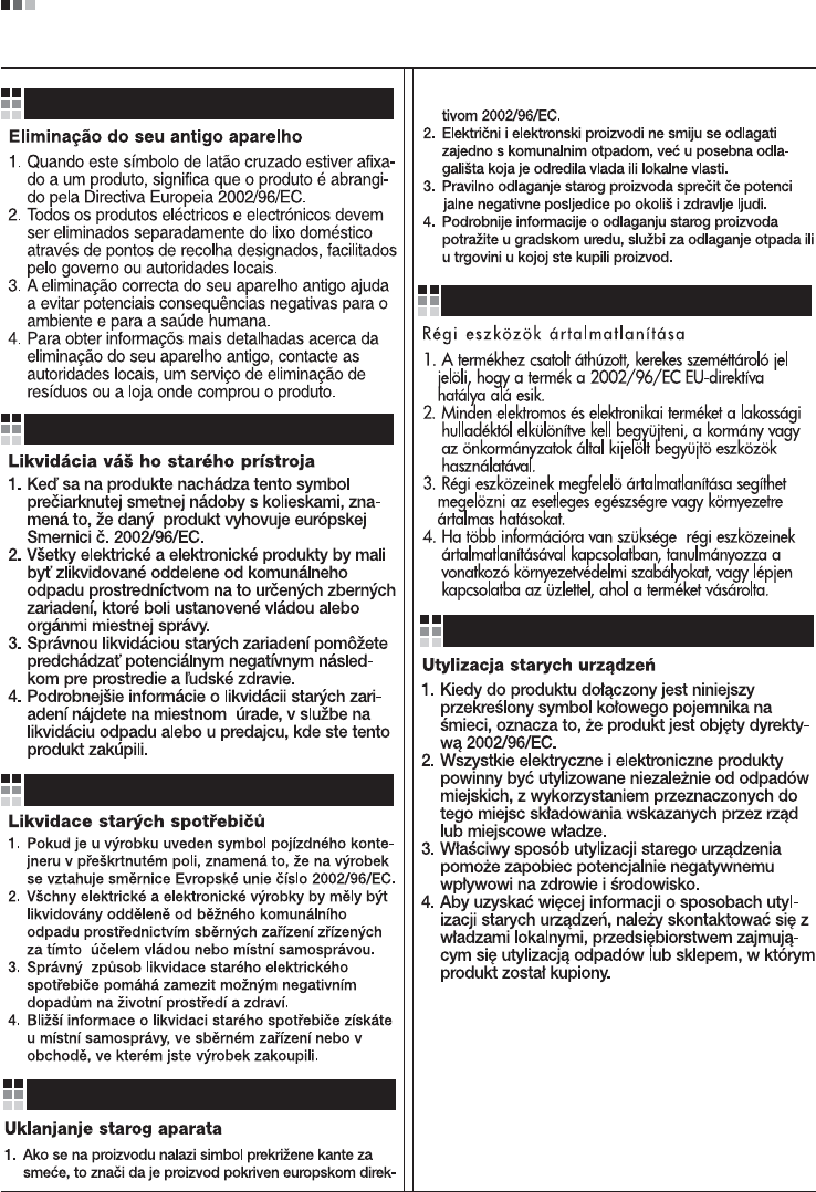
Regulatory Information cont.
10
Portuguese
Slovak
Czech
Croatian
Hungarian
Polish
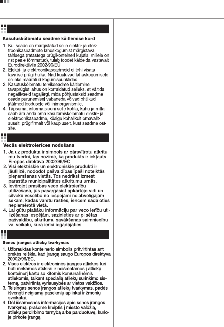
Regulatory Information cont.
11
Estonian
Latvian
Lithuanian