LG Electronics USA HSTND-3411-G LCD MONITOR User Manual EMISSION TEST REPORT
LG Electronics USA LCD MONITOR EMISSION TEST REPORT
UserManual.wiki
>
LG Electronics USA
>
HSTND 3411 G User Manual
Users Manual
Navigation menu
Upload a User Manual
Namespaces
Wiki Guide
HTML
PDF
Info
Views
User Manual
Discussion / Help
Navigation
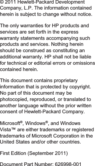

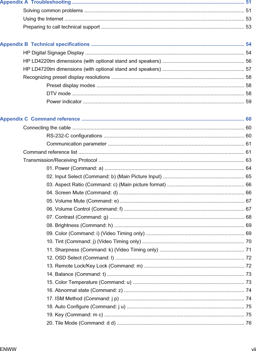
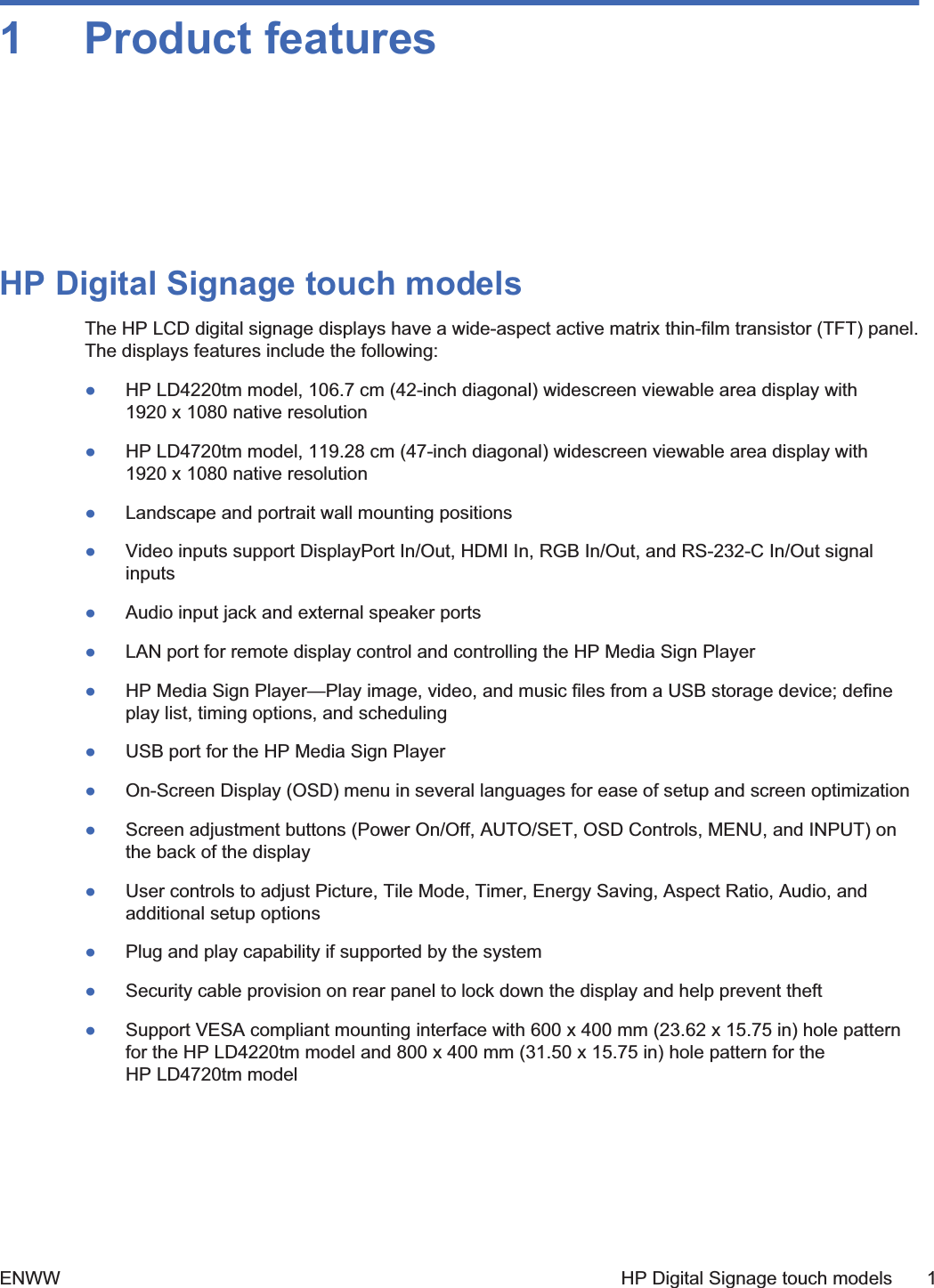
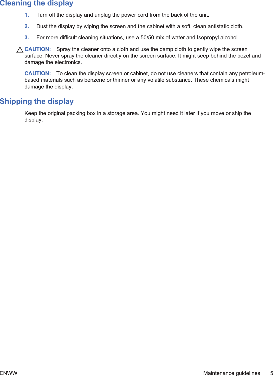
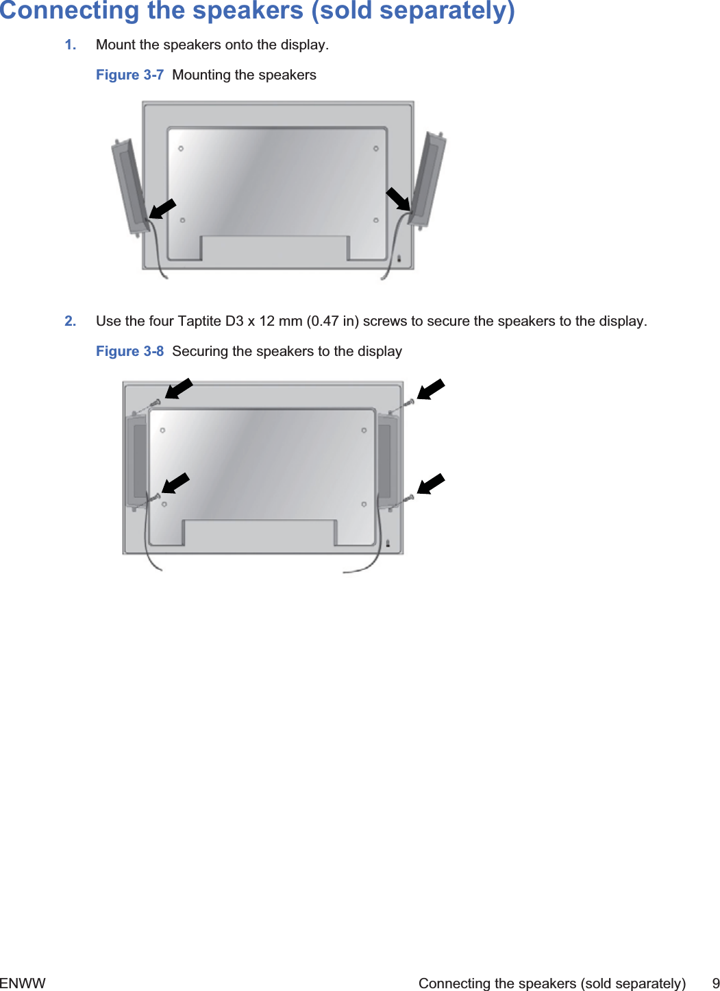
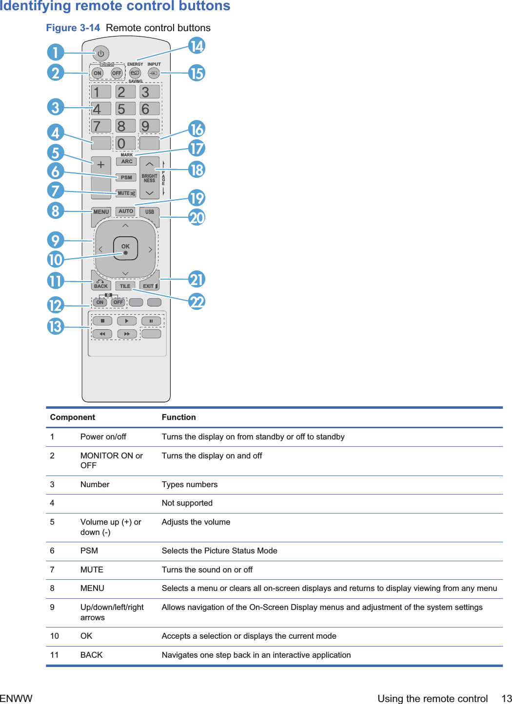
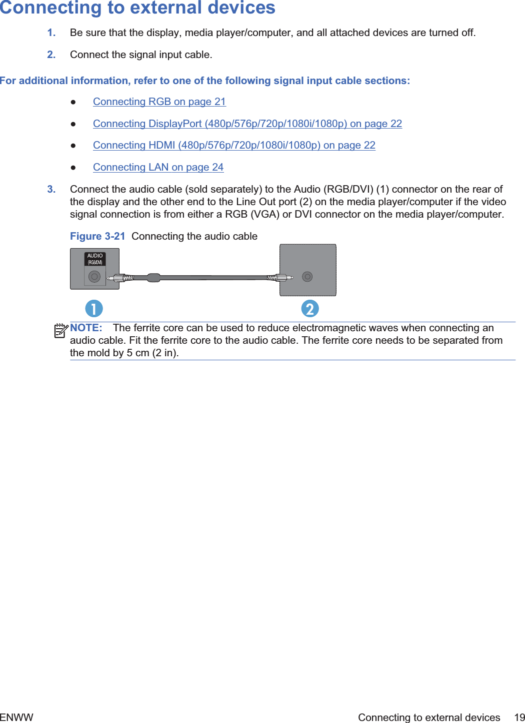
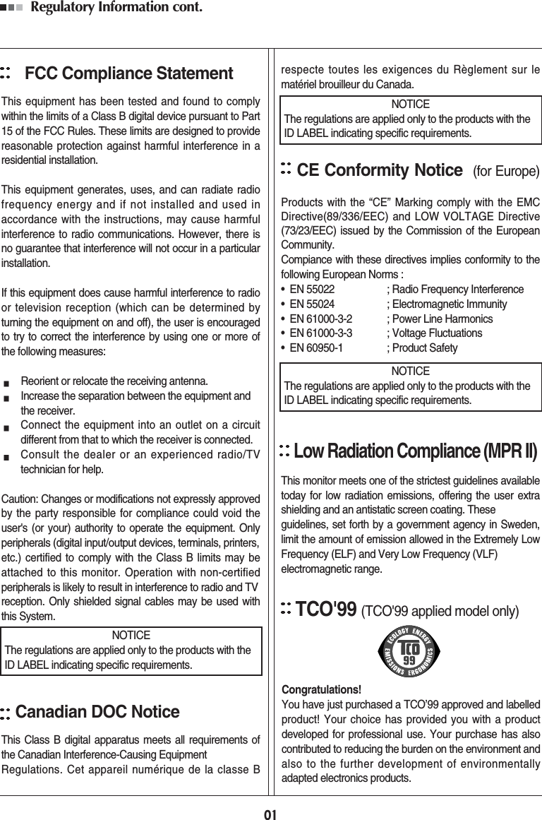
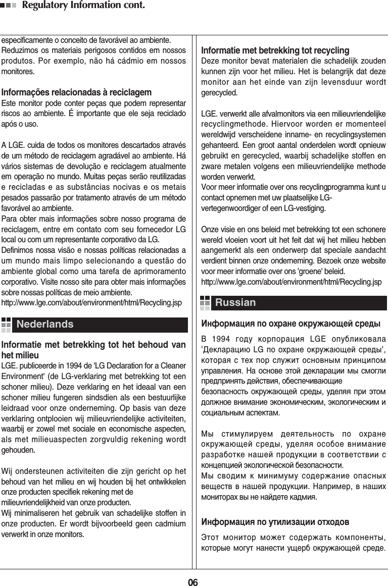
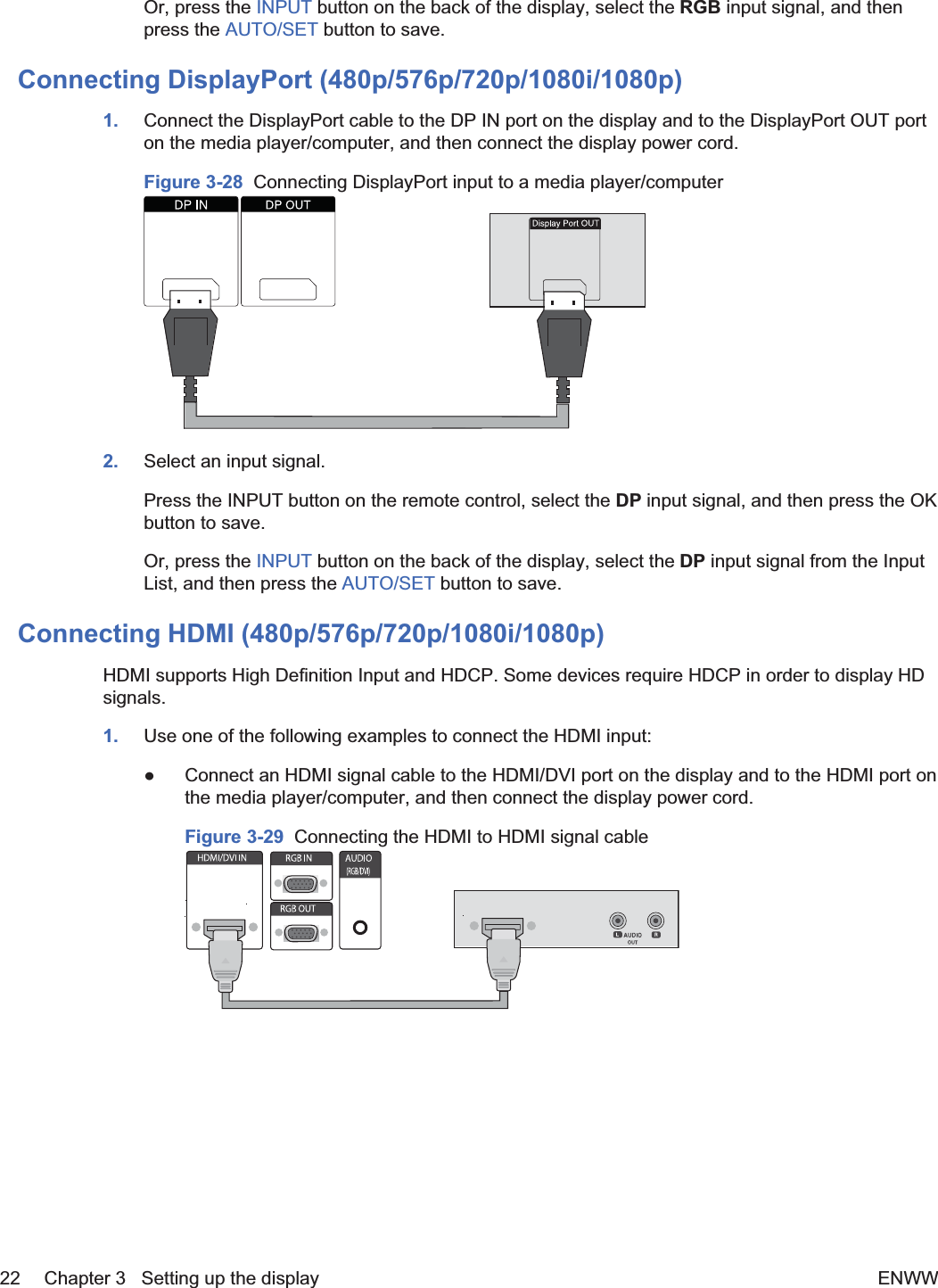
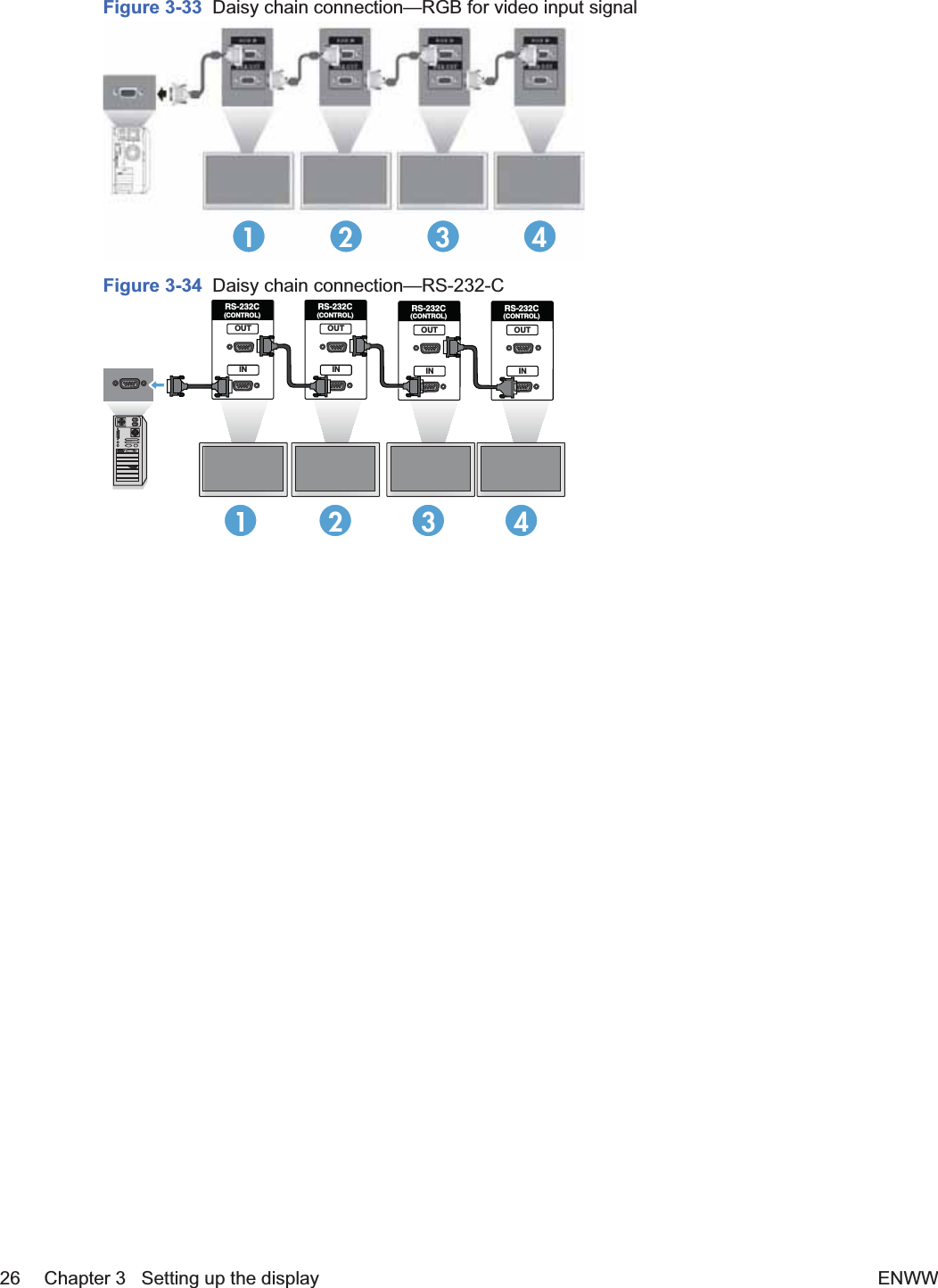
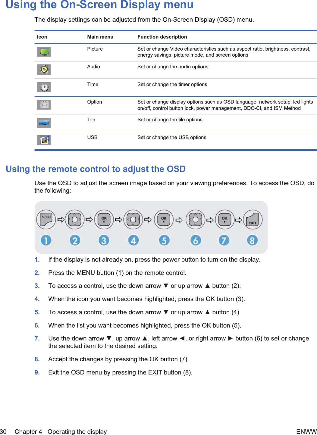
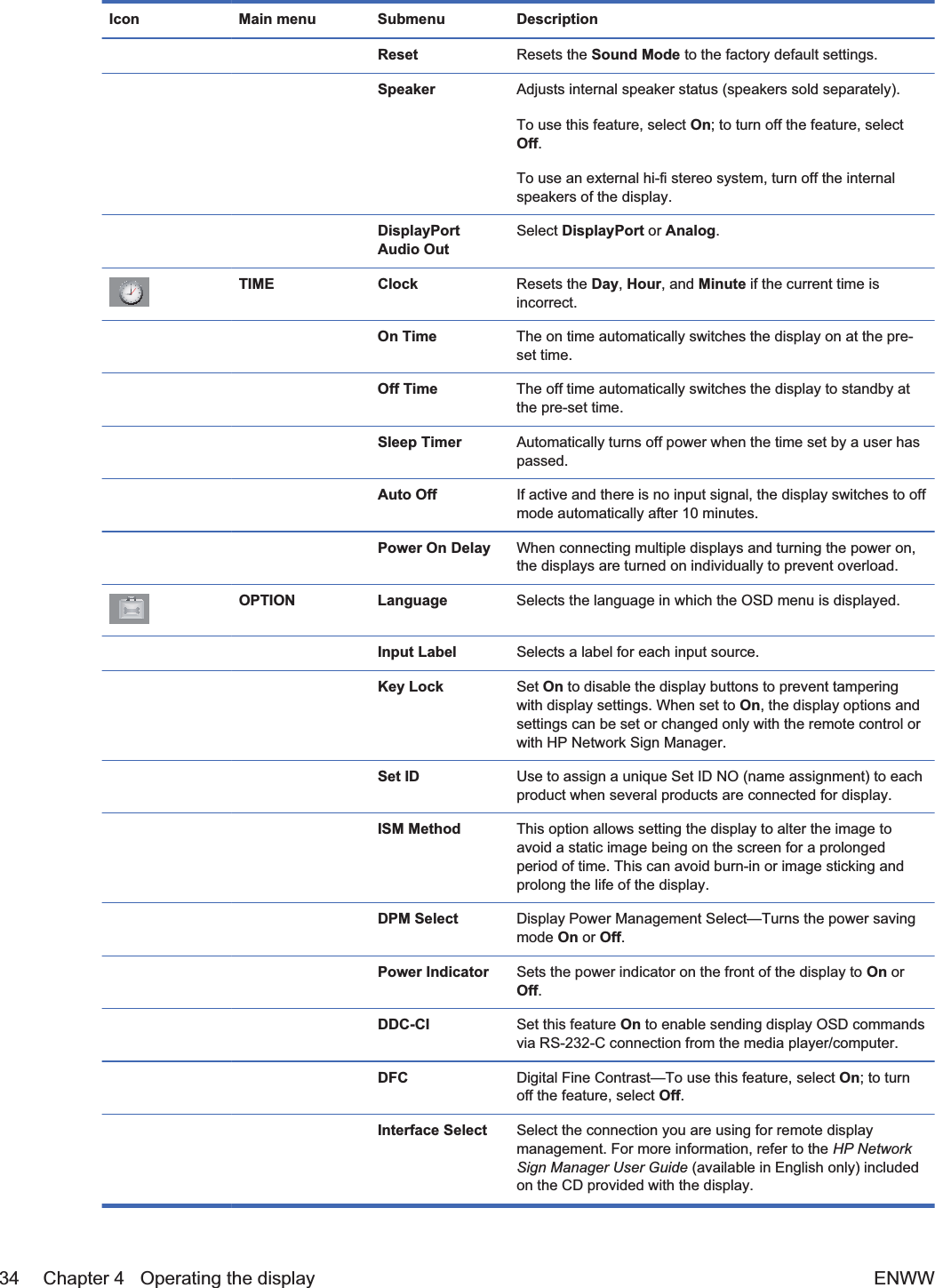
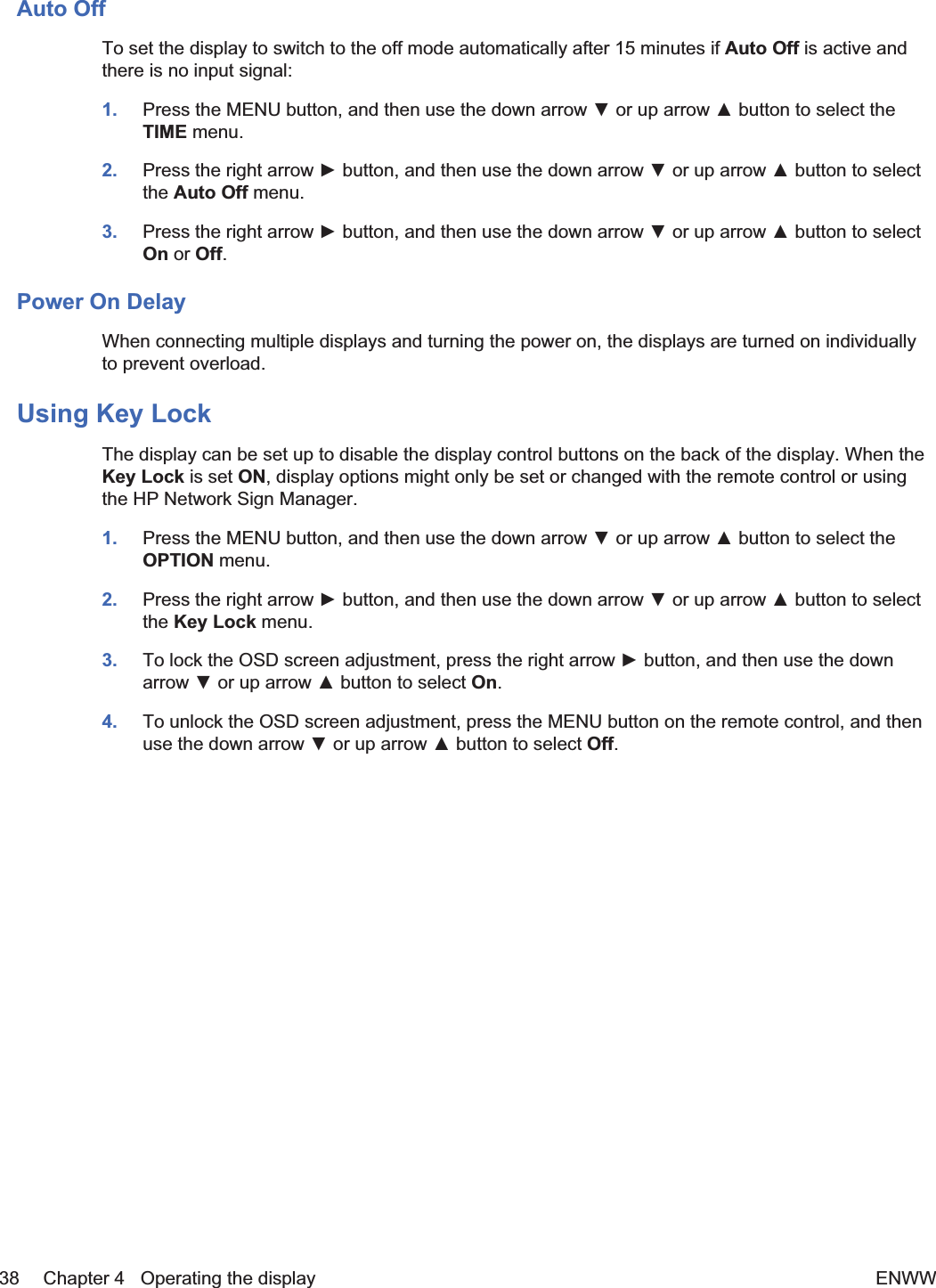
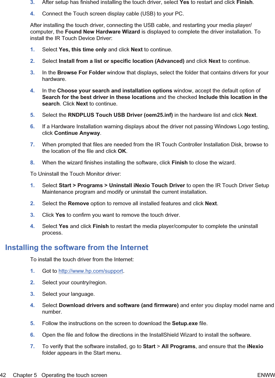
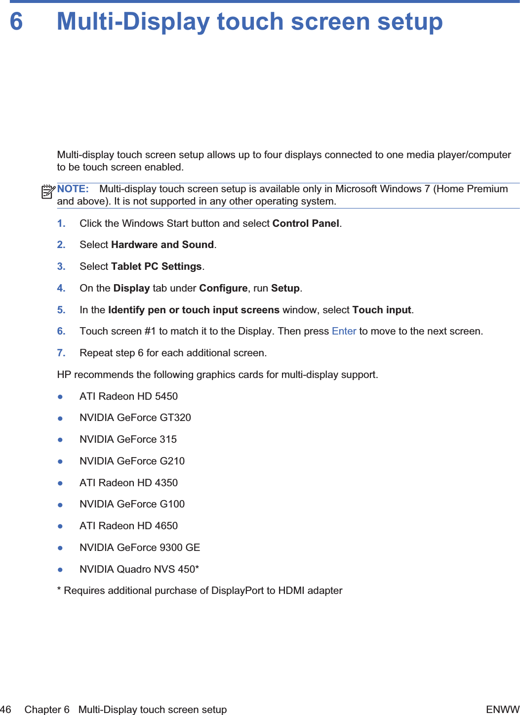
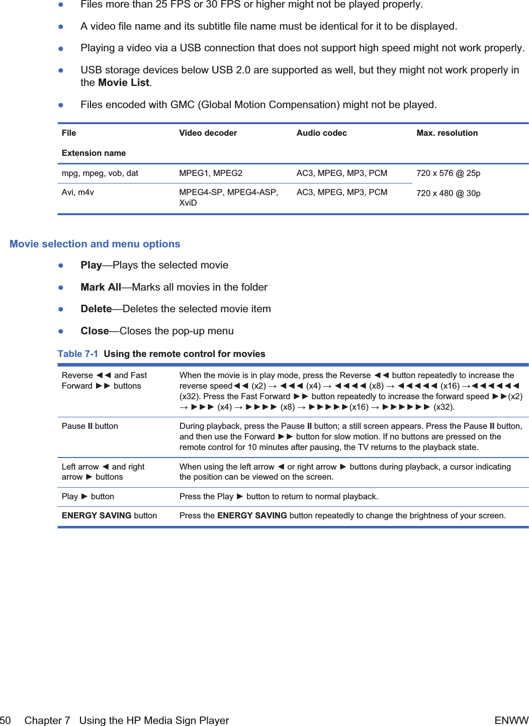
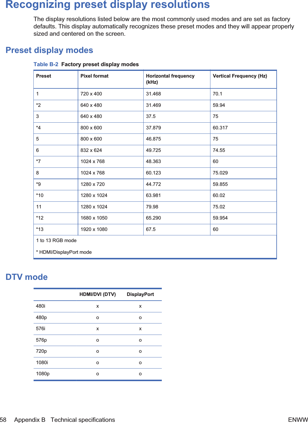
![6. Turn on the media player/computer.7. Select an input signal:Press the INPUT button on the remote control to open the Input List, select the appropriateinput signal, and then press the OK button to save your change.Or, press the INPUT button on the back of the display, select the appropriate input signal, andthen press the AUTO/SET button to save your change.łWhen connecting with a D-Sub (VGA) signal input cable, select RGB from the Input List.łWhen connecting with an HDMI signal input cable or when connecting a DVI signal inputcable with the HDMI to DVI cable, select HDMI/DVI from the Input List.łWhen connecting with a DisplayPort signal input cable, select DP from the Input List.NOTE: If connecting more than one input source, connect the signal cables [HDMI/DVI, RGB(VGA), and DisplayPort] to each media player/computer. Press the INPUT button on the remotecontrol to select the input to view.Connecting RGB1. For analog operation, connect the D-Sub signal cable to the RGB IN (1) connector on the rear ofthe display and the other end to the connector (2) on the media player/computer.NOTE: If connecting to a Mac media player/computer, use the standard Mac adapter (3)–notincluded.Figure 3-26 Connecting the D-Sub signal cable1232. Connect the audio cable (sold separately) to the Audio (RGB/DVI) (1) connector on the rear ofthe display and the other end to the Line Out port (2) on the media player/computer if the videosignal connection is from either a RGB (VGA) or DVI connector on the media player/computer.Figure 3-27 Connecting the audio cable123. Select an input signal:Press the INPUT button on the remote control, select the RGB input signal, and then press theOK button to save.ENWW Connecting to external devices 21](https://usermanual.wiki/LG-Electronics-USA/HSTND-3411-G/User-Guide-1487016-Page-32.png)
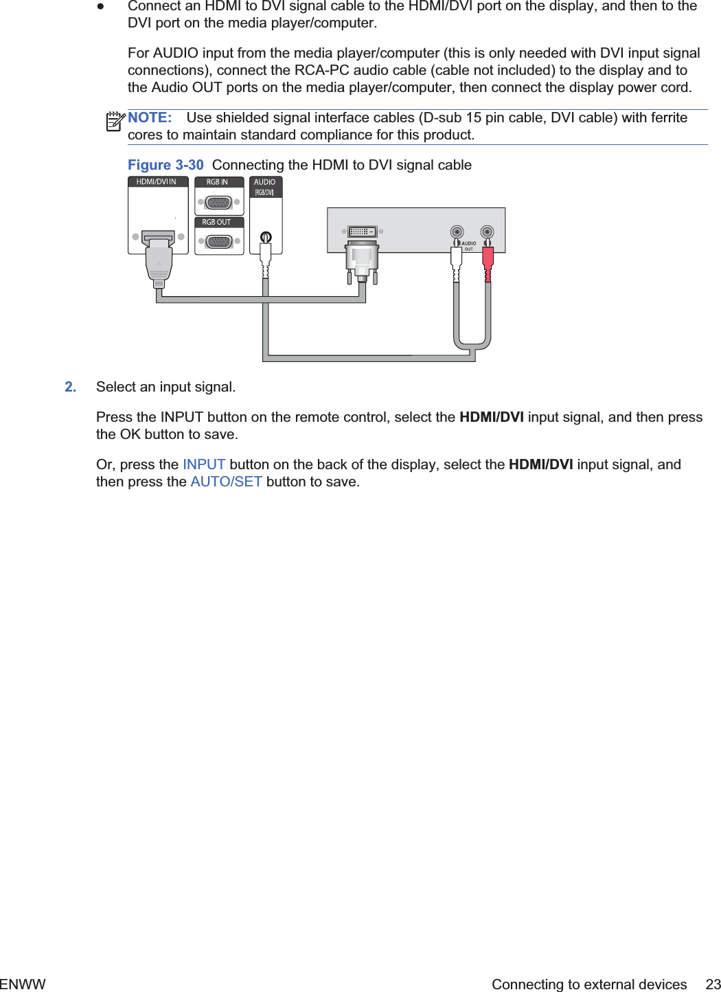
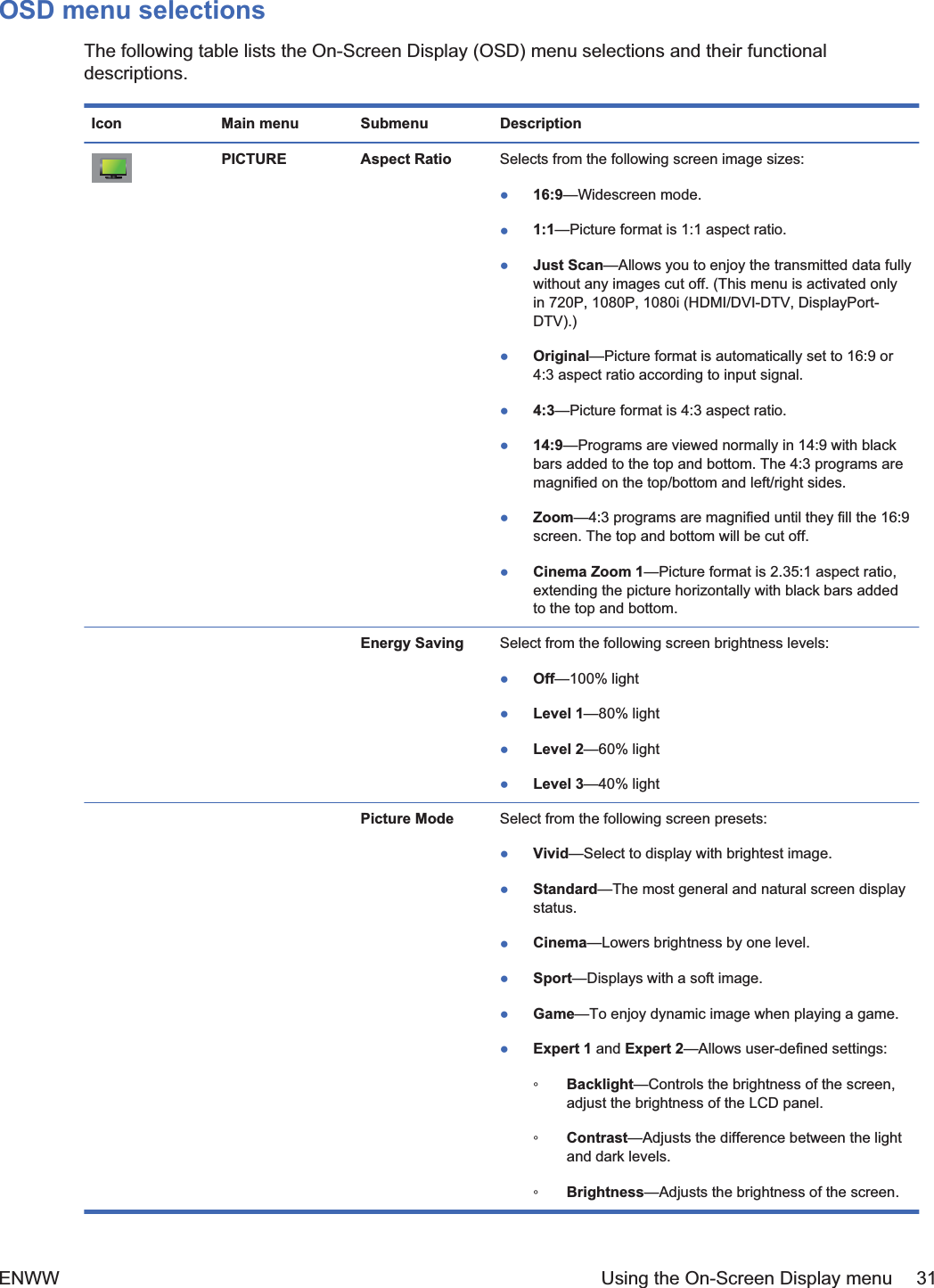
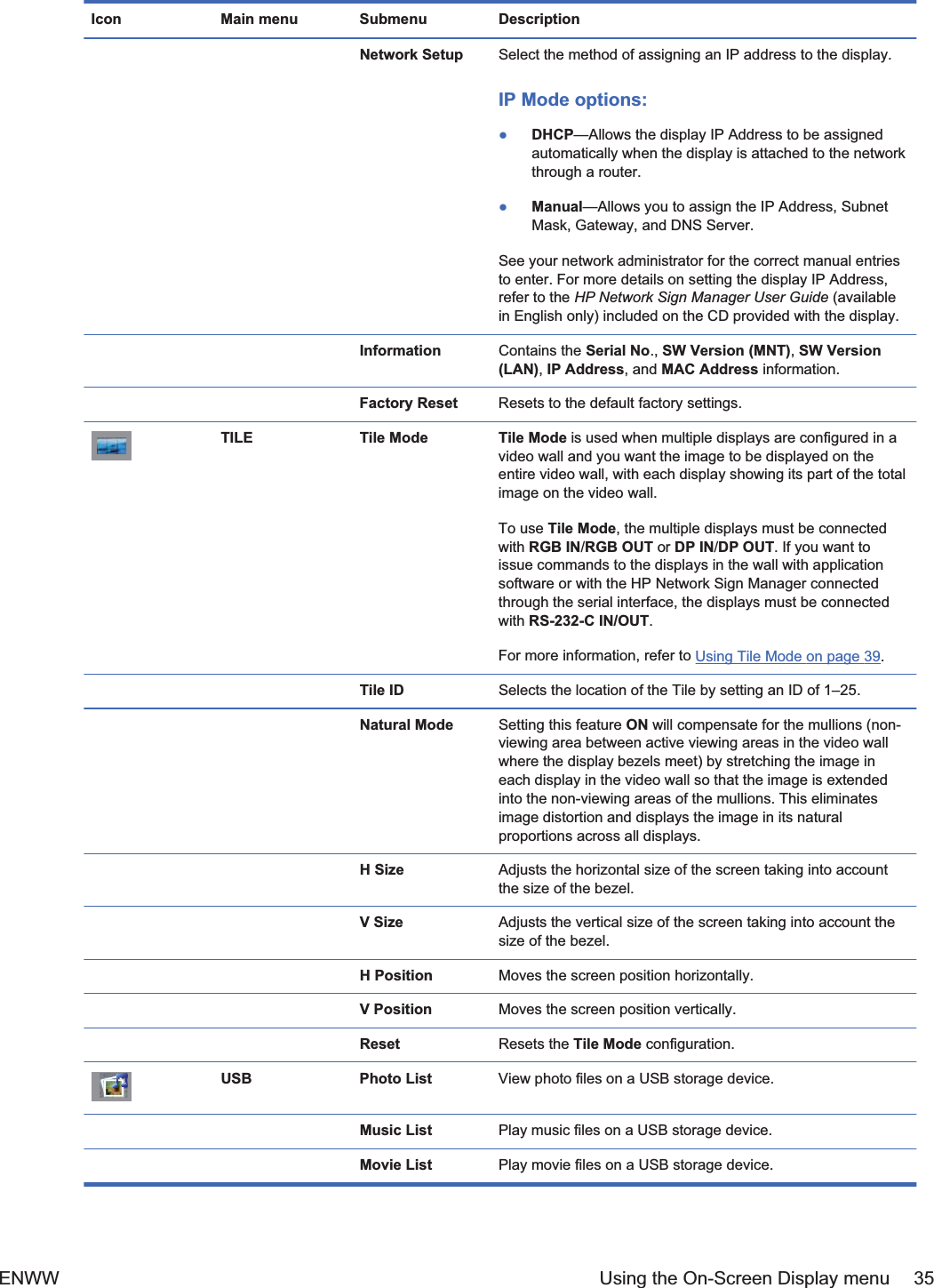
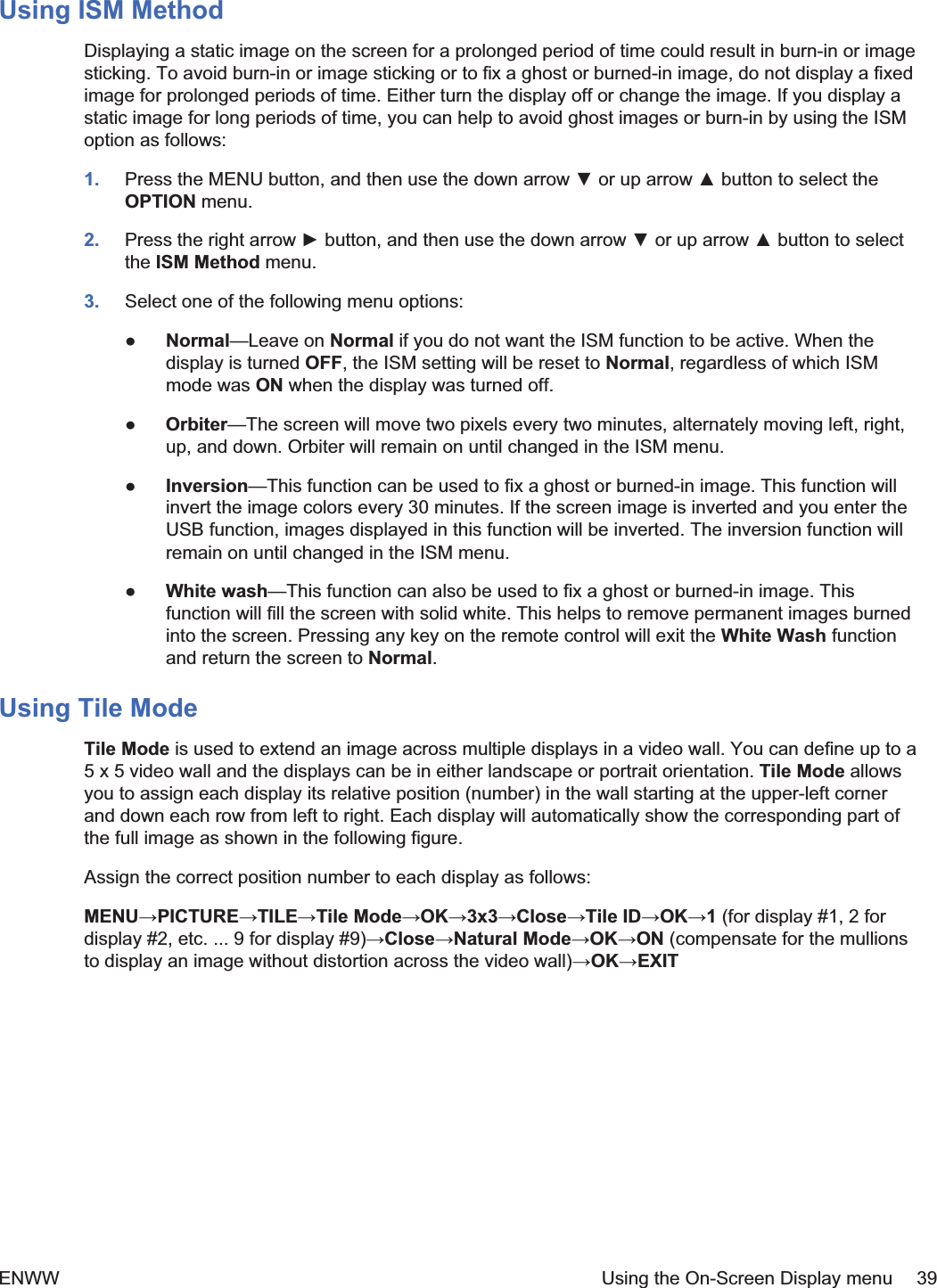
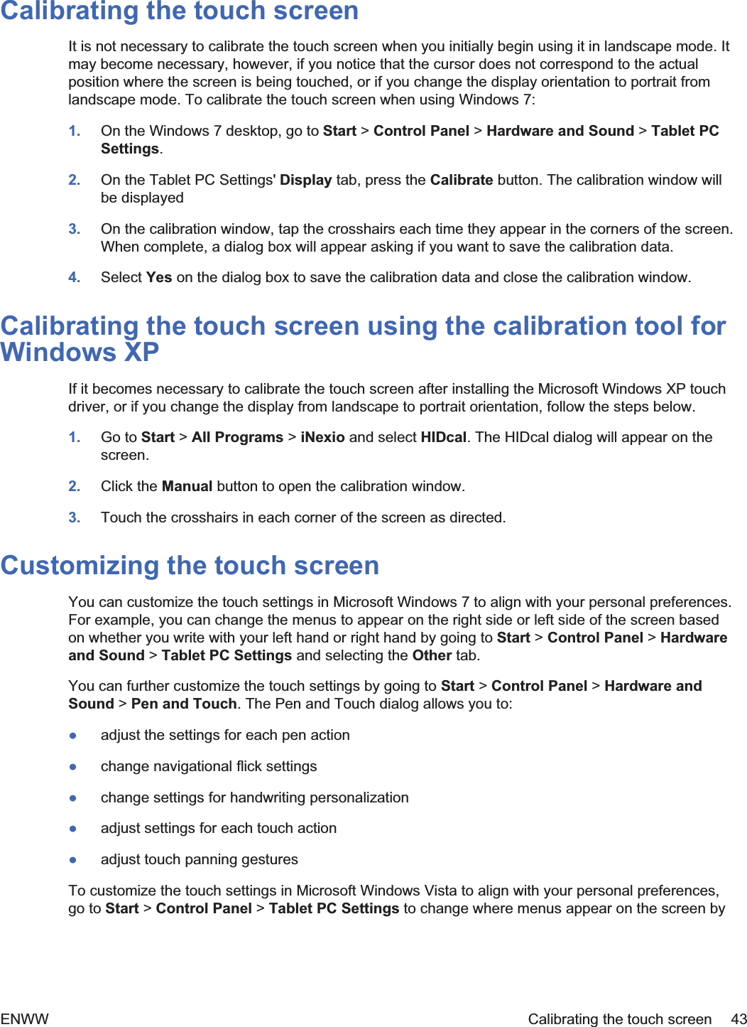
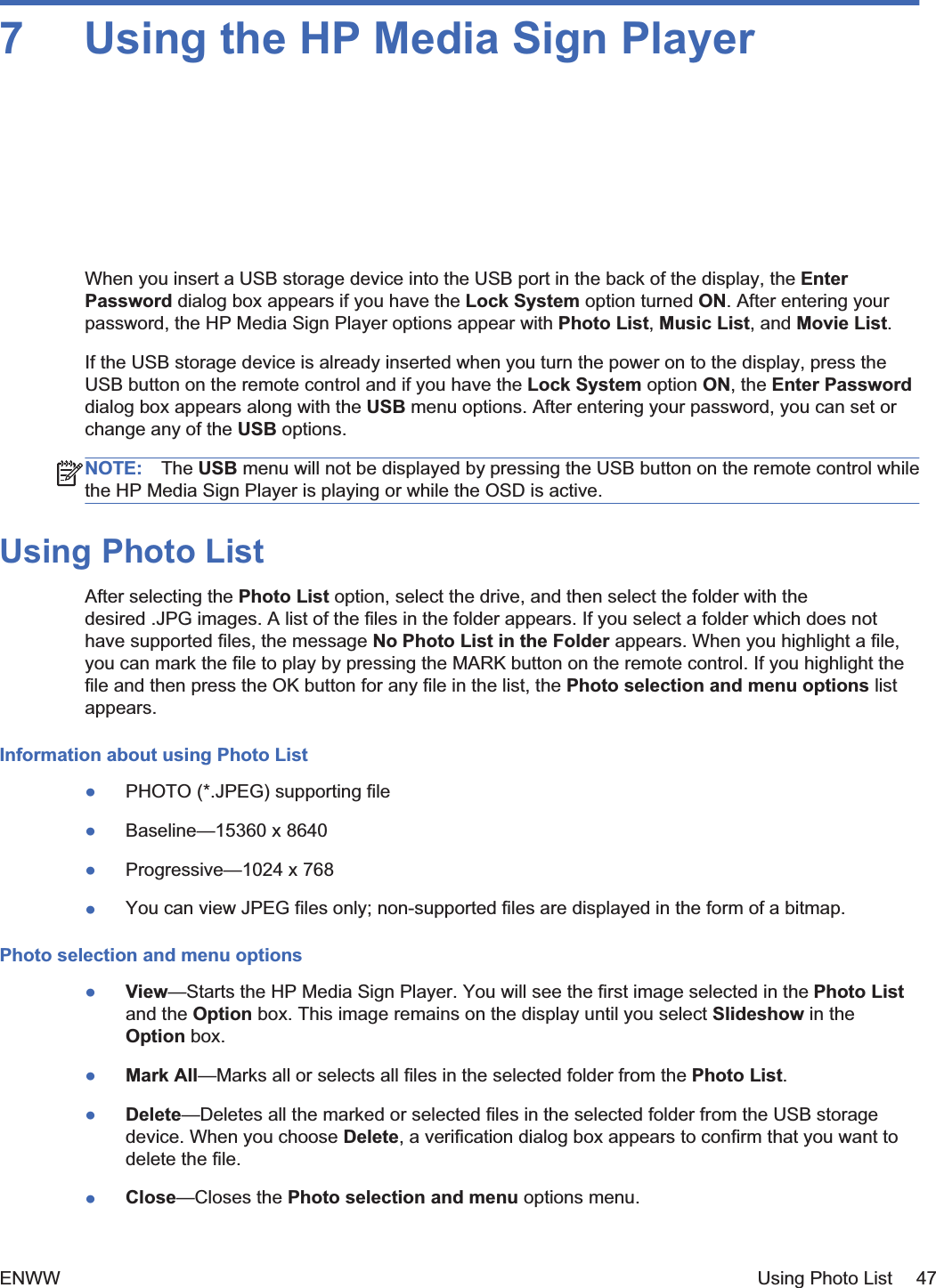
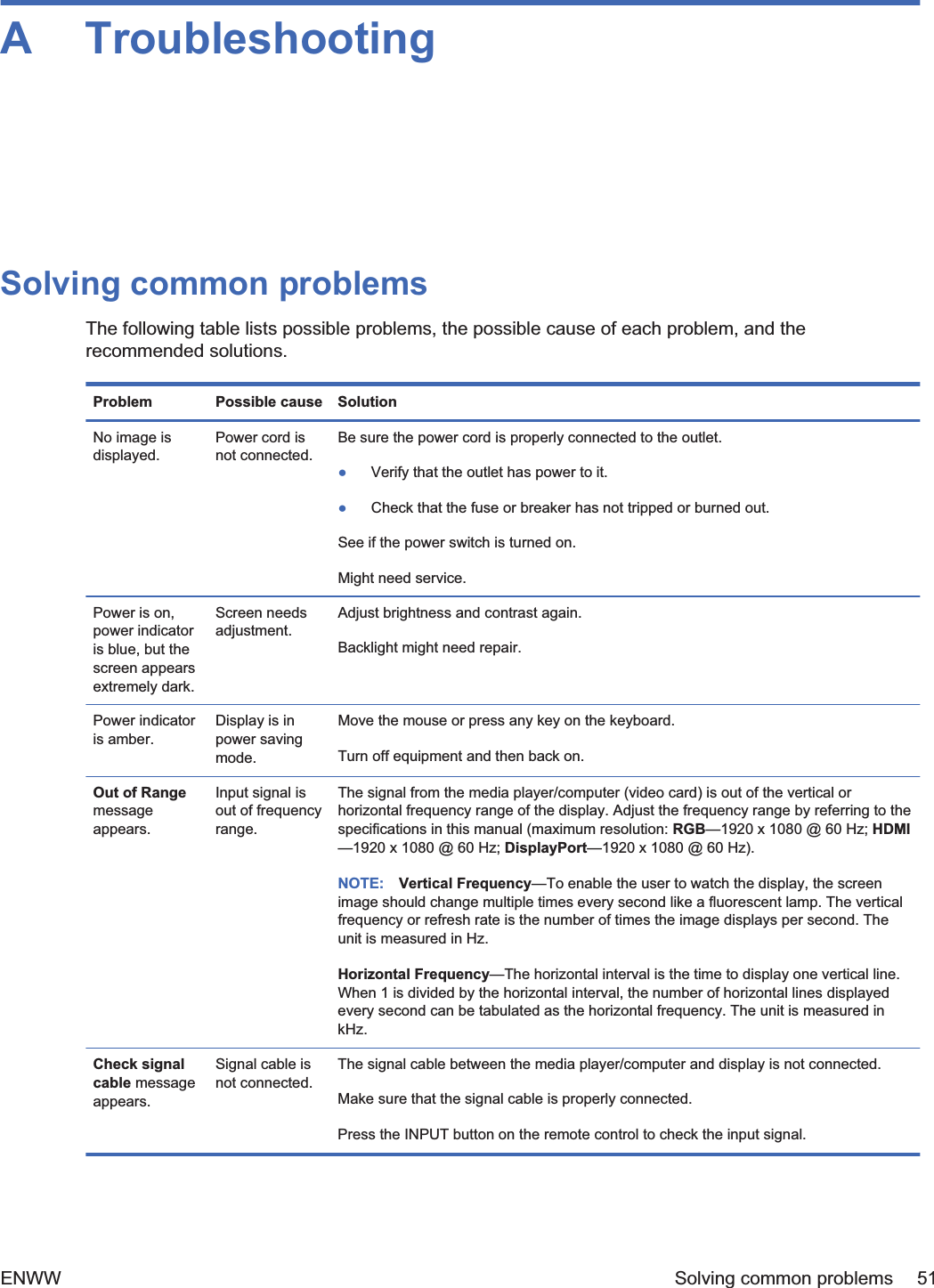
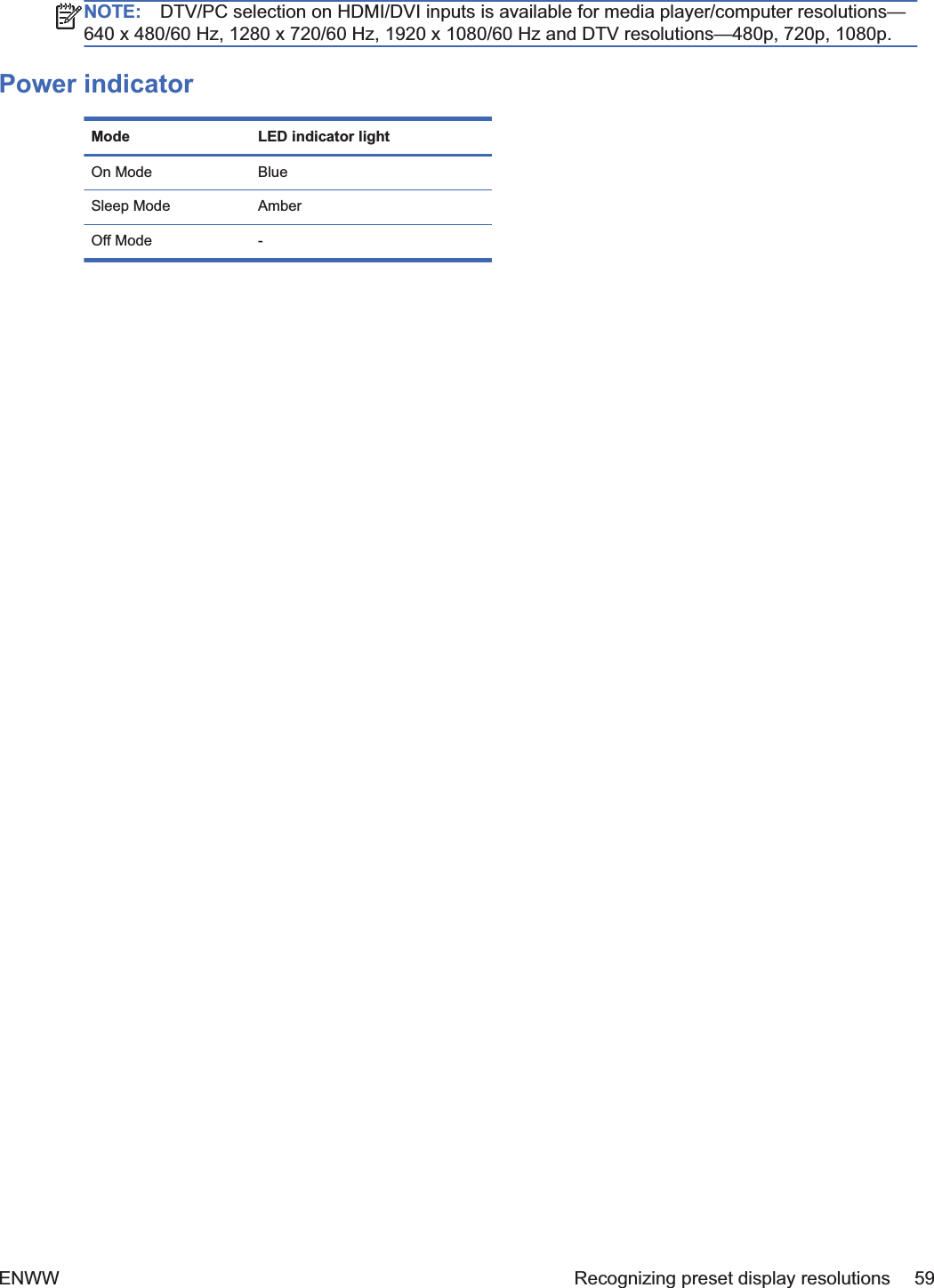
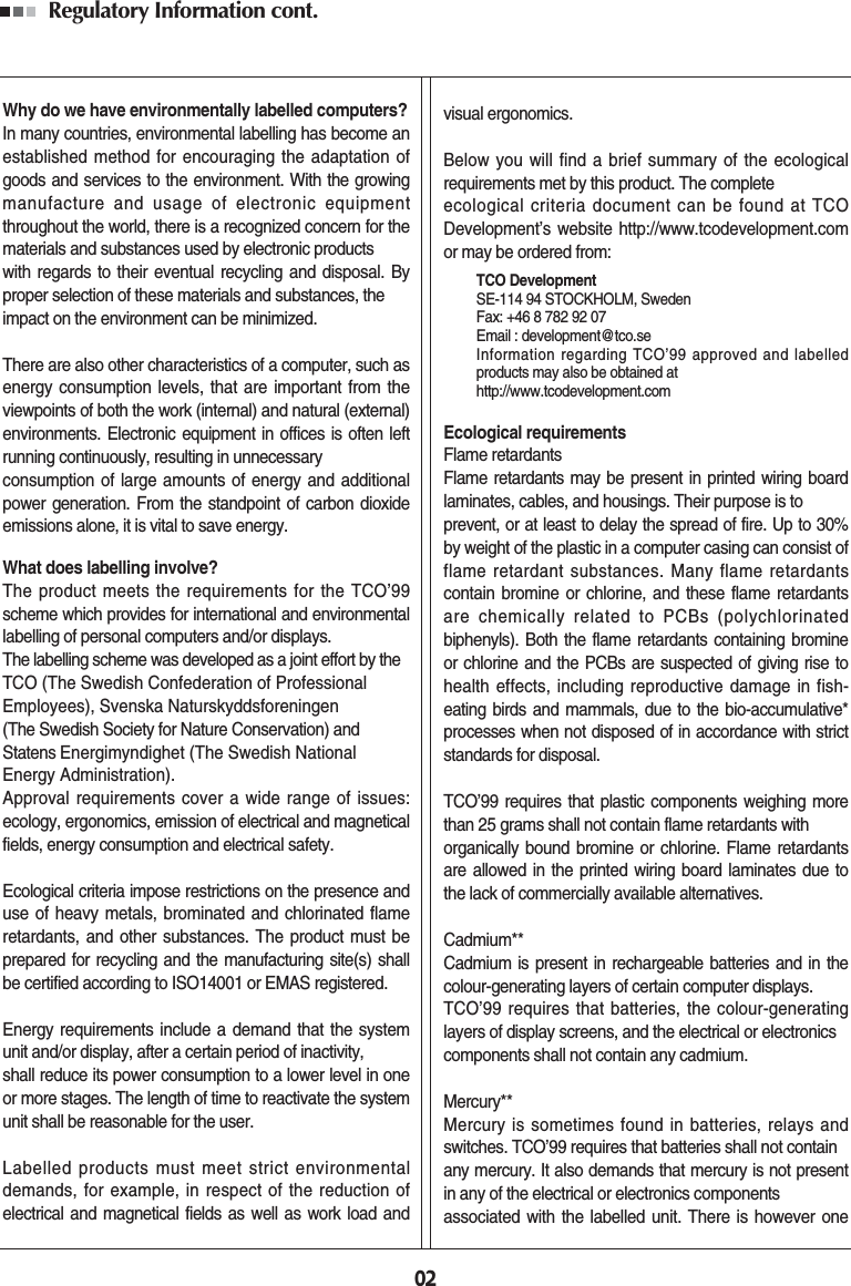
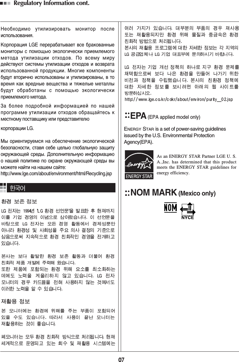
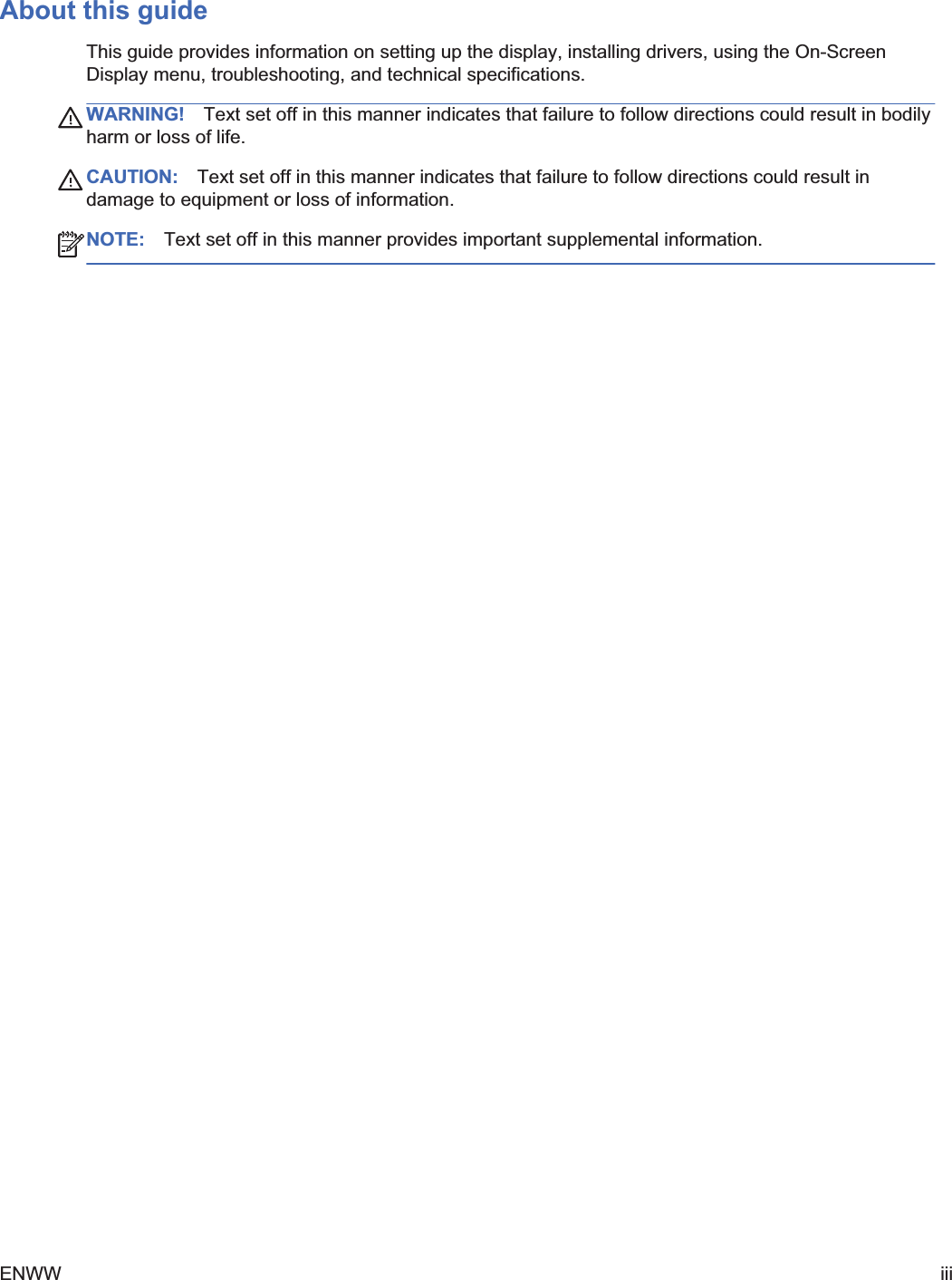
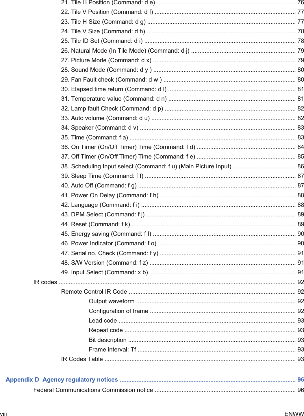
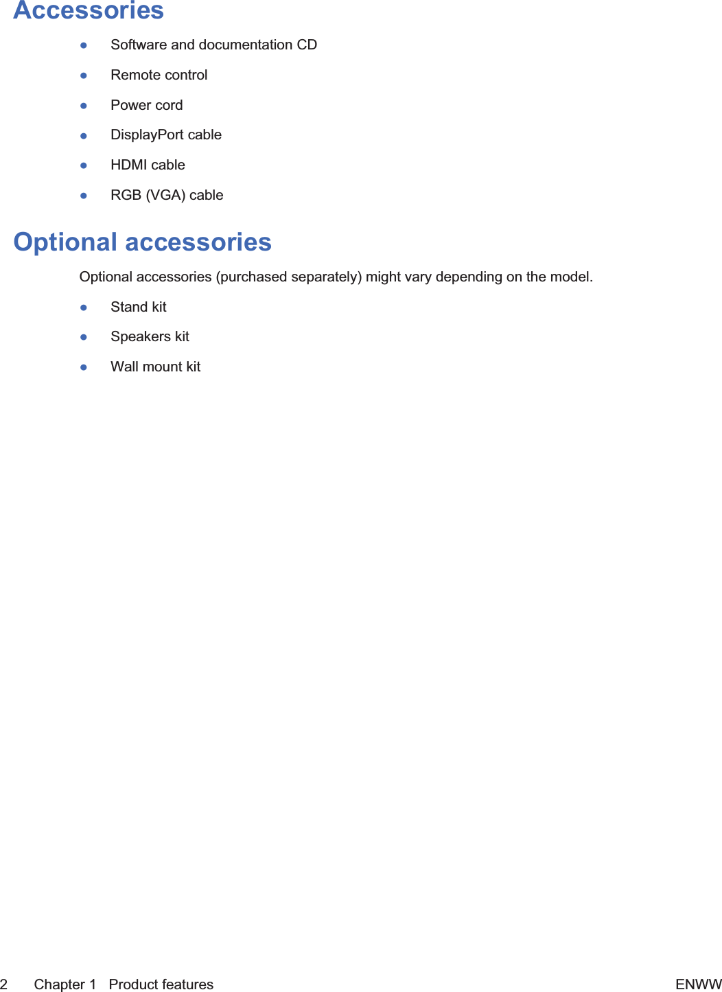
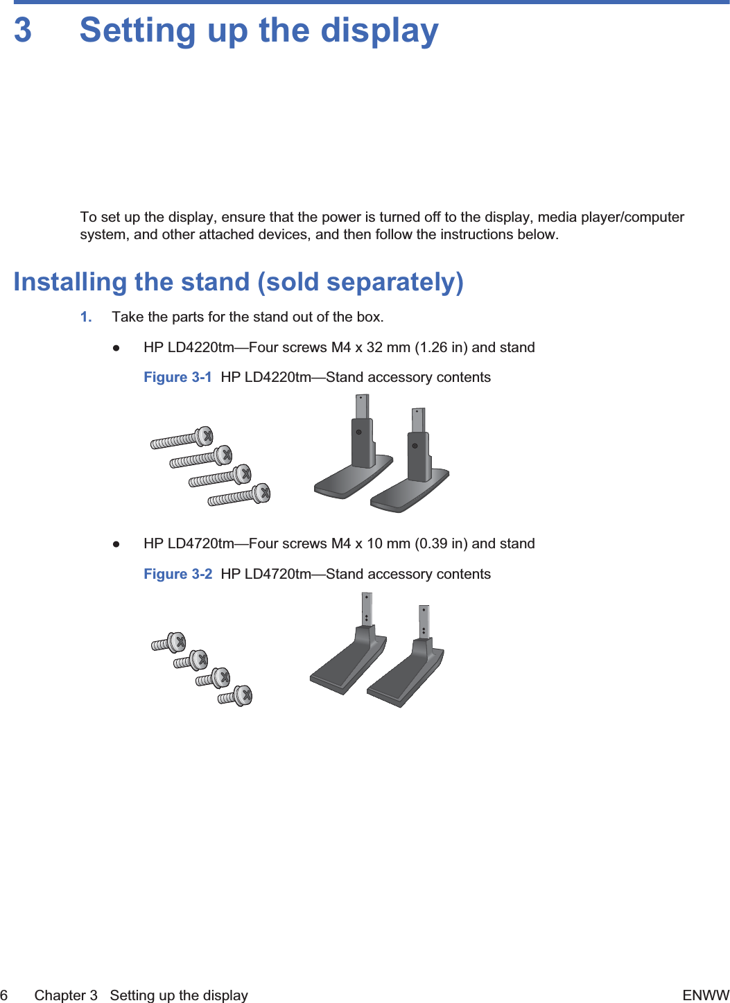
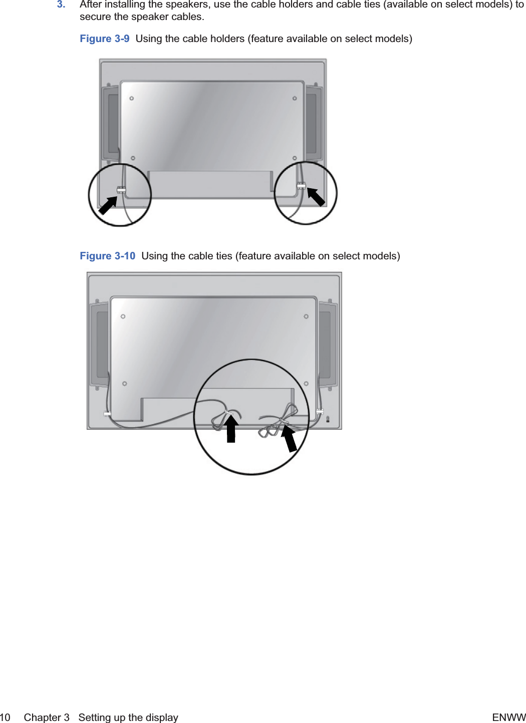
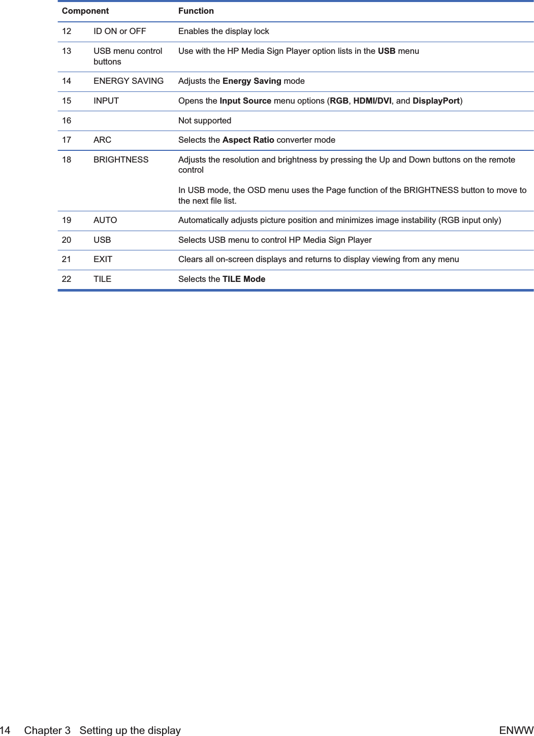
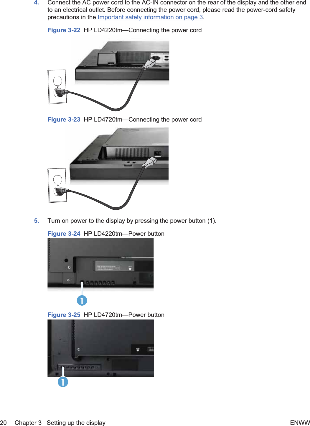
![COMMAND1 COMMAND2 DATA1 DATA2 DATA347. Serial No. f y FFH 48. S/W Verison f z FFH 49. Input Select x b 60H–C0H Transmission/Receiving ProtocolTransmission[Command1][Command2][][Set ID][][Data][Cr]*[Command 1] First command (k, j, m, d, f, x)*[Command 2] Second command (a to z)*[Set ID] Set up the Set ID number of product. range: 01H to 63H. by setting'0', server can control all products.When operating with more than 2 sets using set ID as '0' at thesame time, do not check the ack message. Because all sets willsend the ack message, it is not possible to check all of the ackmessages.*[Data] To transmit command data.Transmit 'FF' data to read status of command.*[Cr] Carriage ReturnASCII code '0 x 0 D'*[] ASCII code Space (0 x 20)OK Acknowledgement[Command2][][Set ID][][OK][Data][x]*The Product transmits ACK (acknowledgement) based on this format when receiving normal data. Atthis time, if the data is in data read mode, it indicates present status data. If the data is in data writemode, it returns the data of the media player/computer.Error Acknowledgement[Command2][][Set ID][][NG][Data][x]If there is an error, it returns NGENWW Transmission/Receiving Protocol 63](https://usermanual.wiki/LG-Electronics-USA/HSTND-3411-G/User-Guide-1487016-Page-74.png)
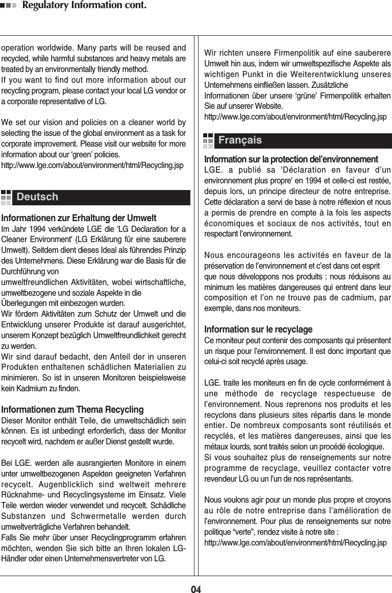
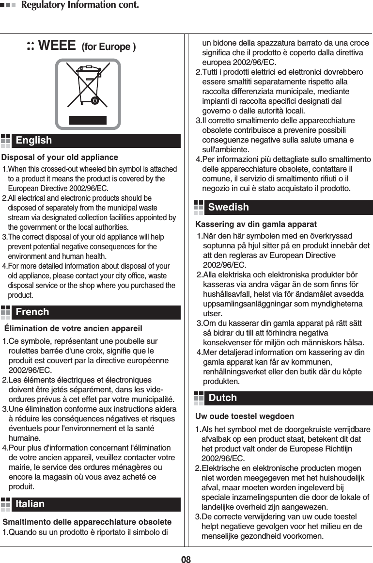
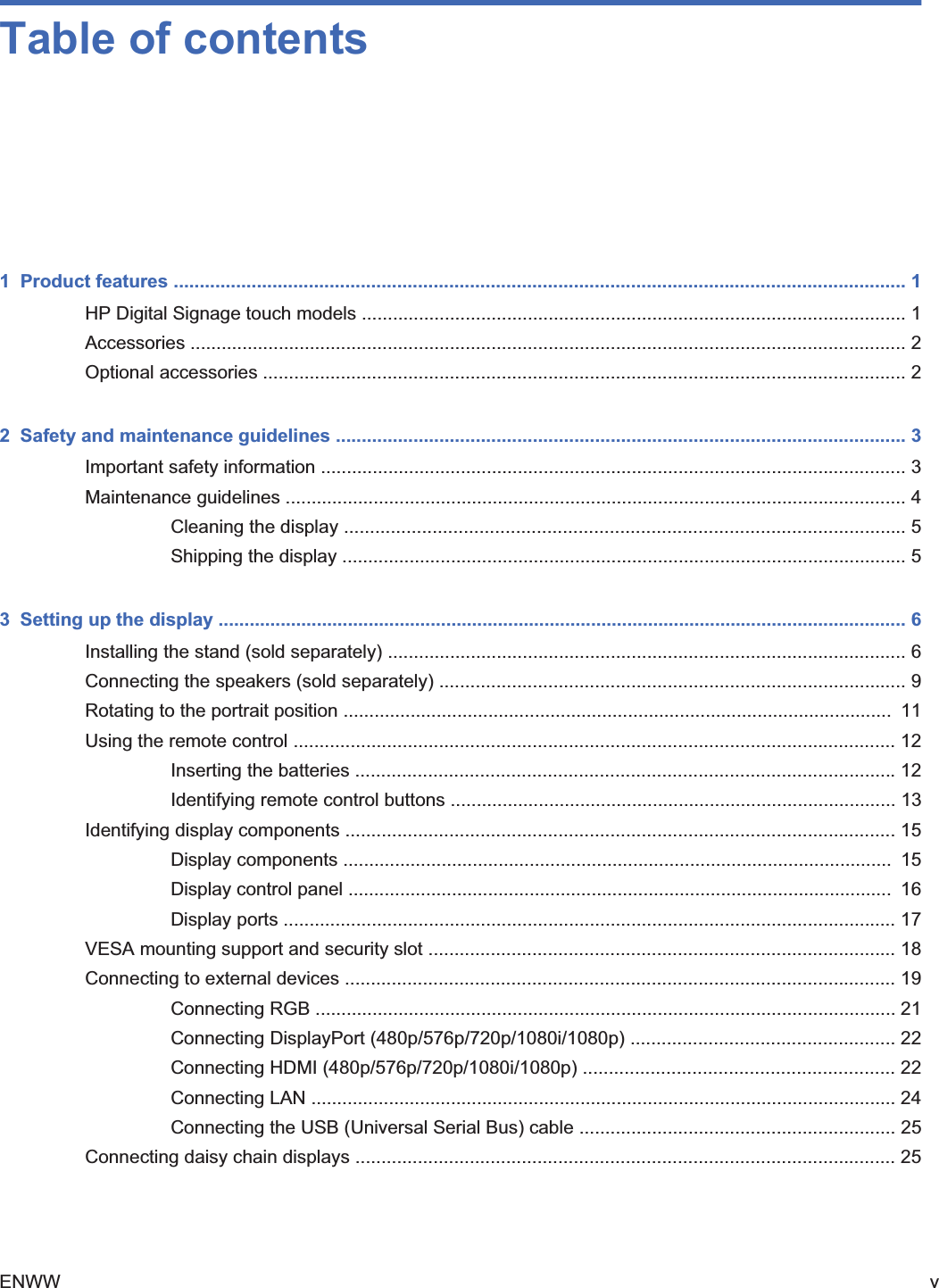
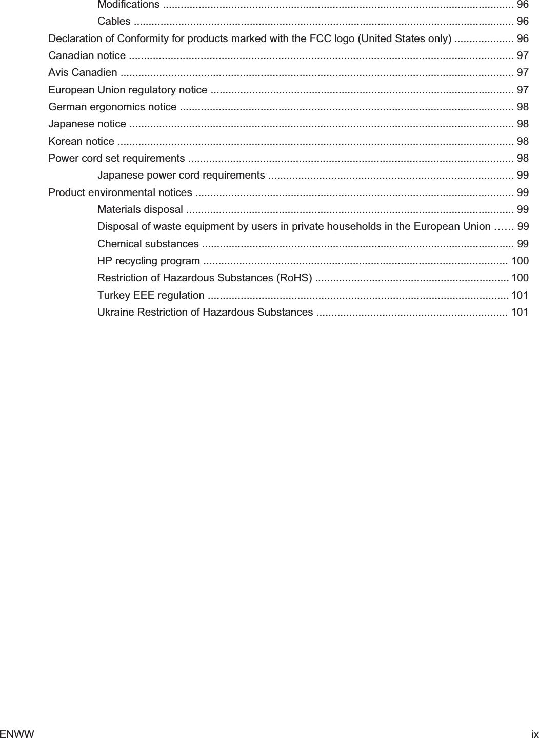
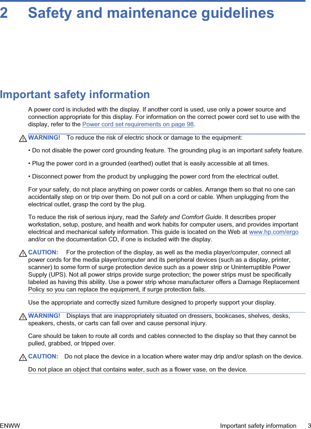
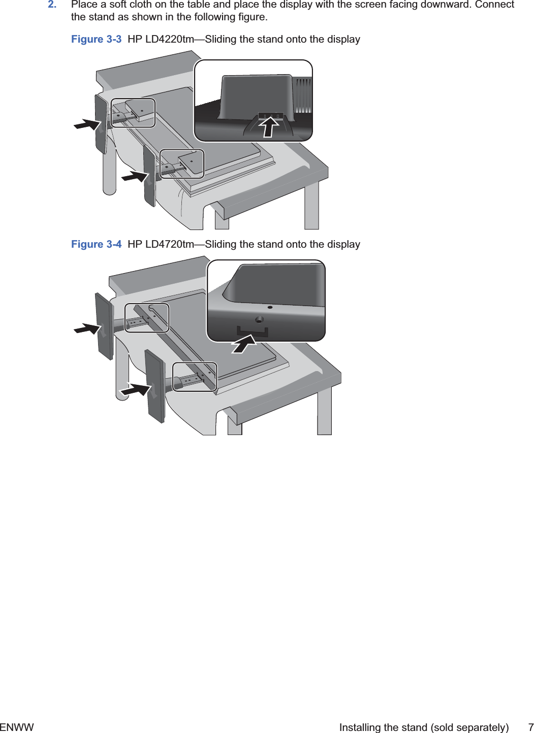
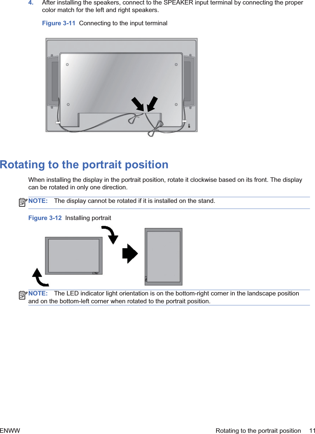
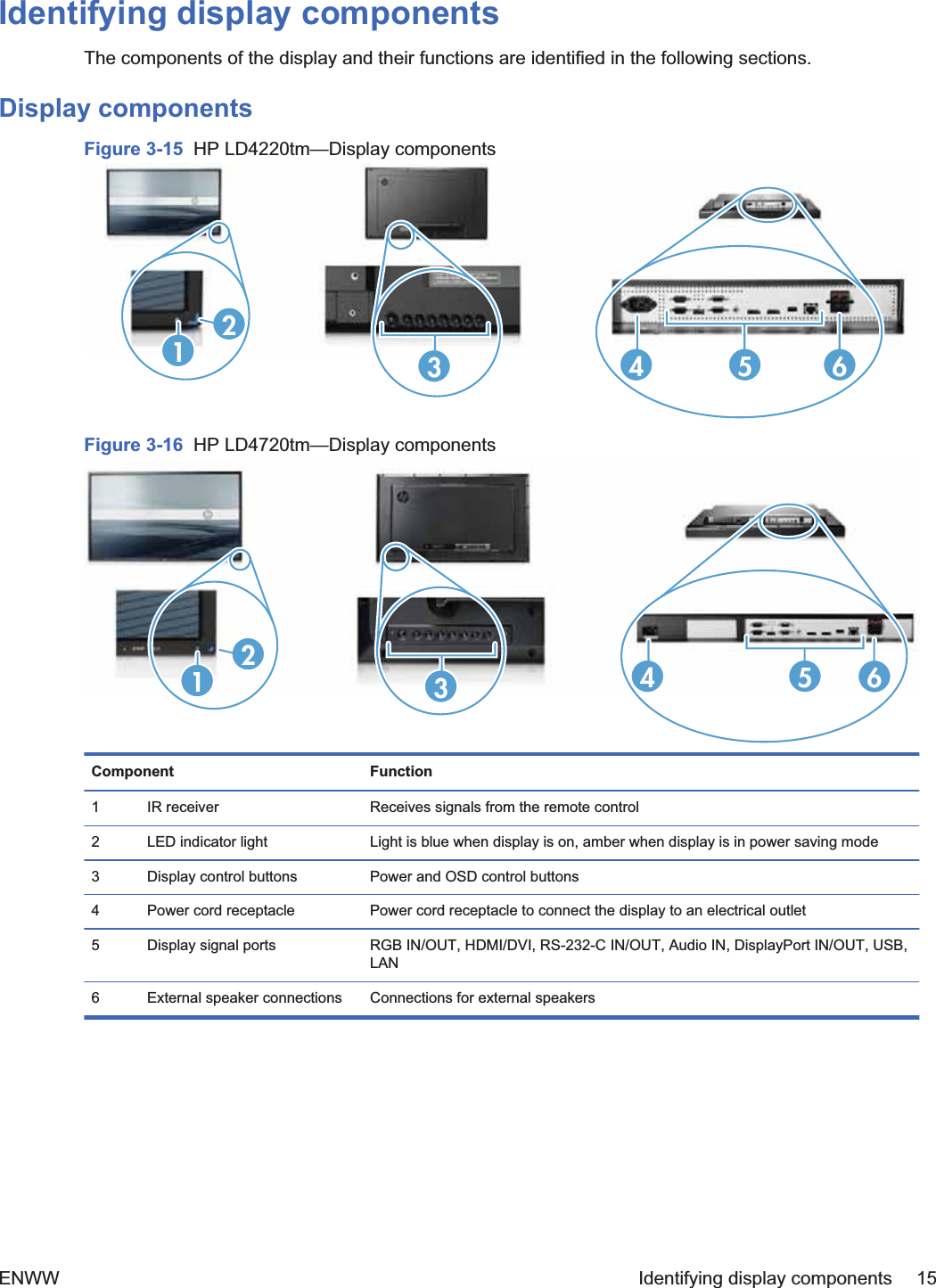
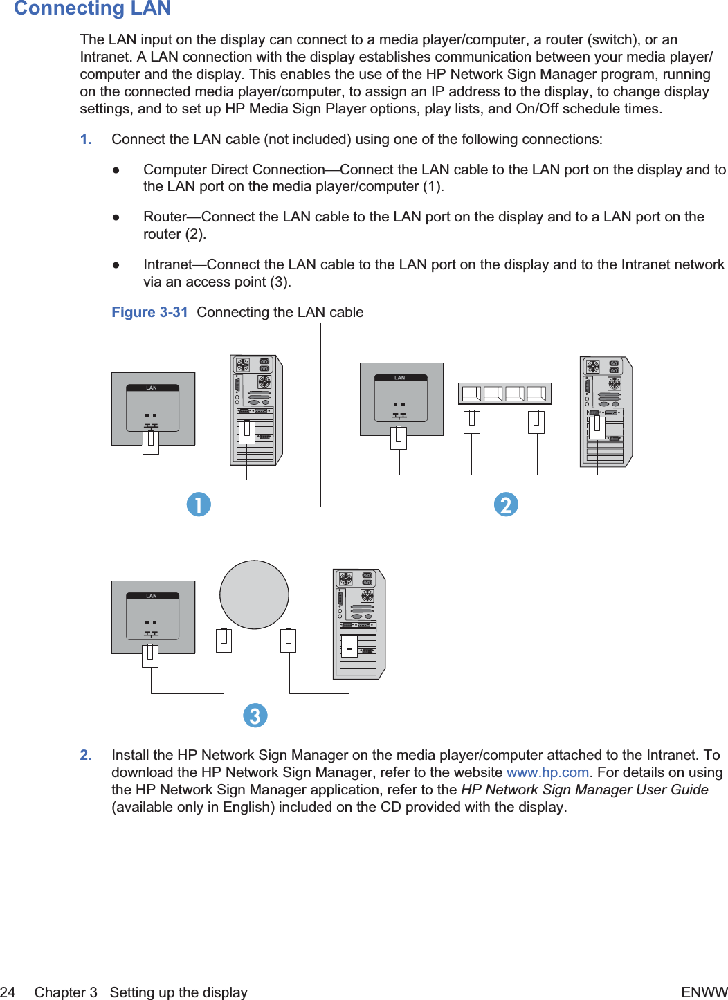
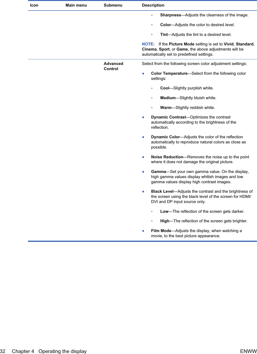
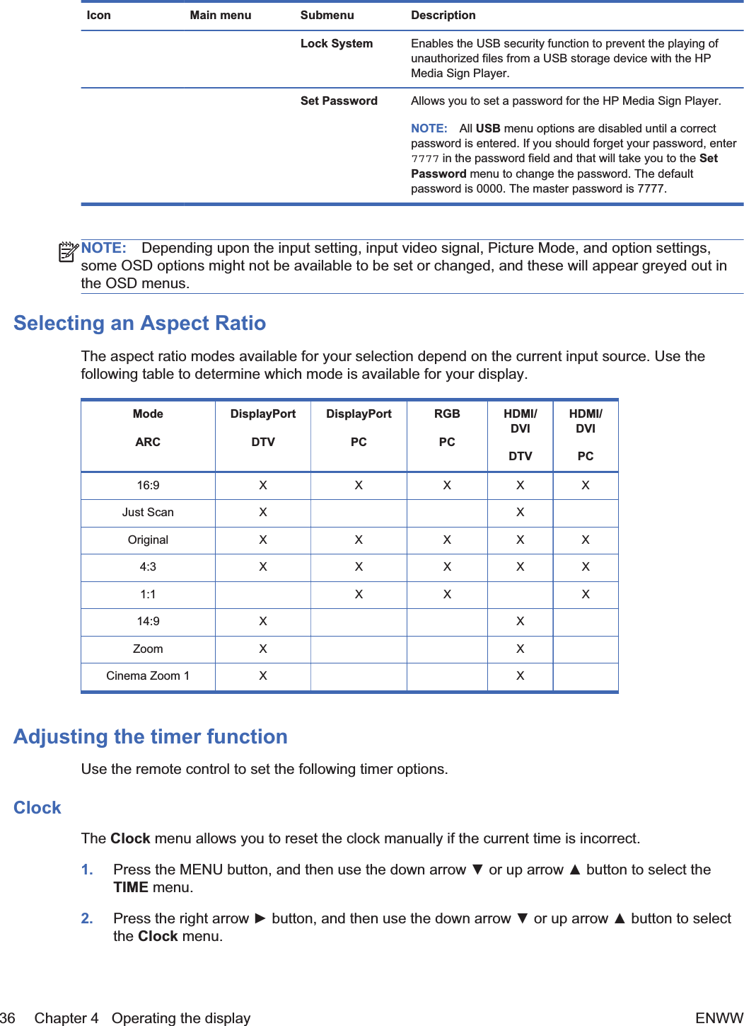
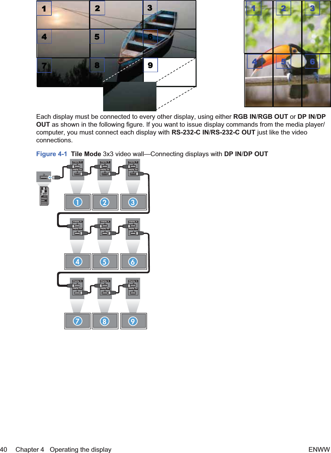
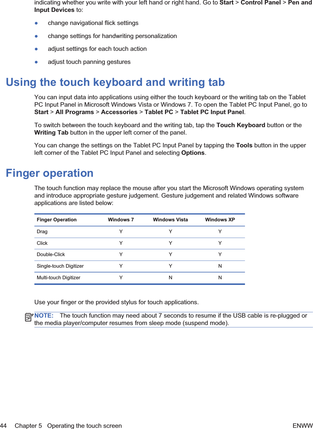
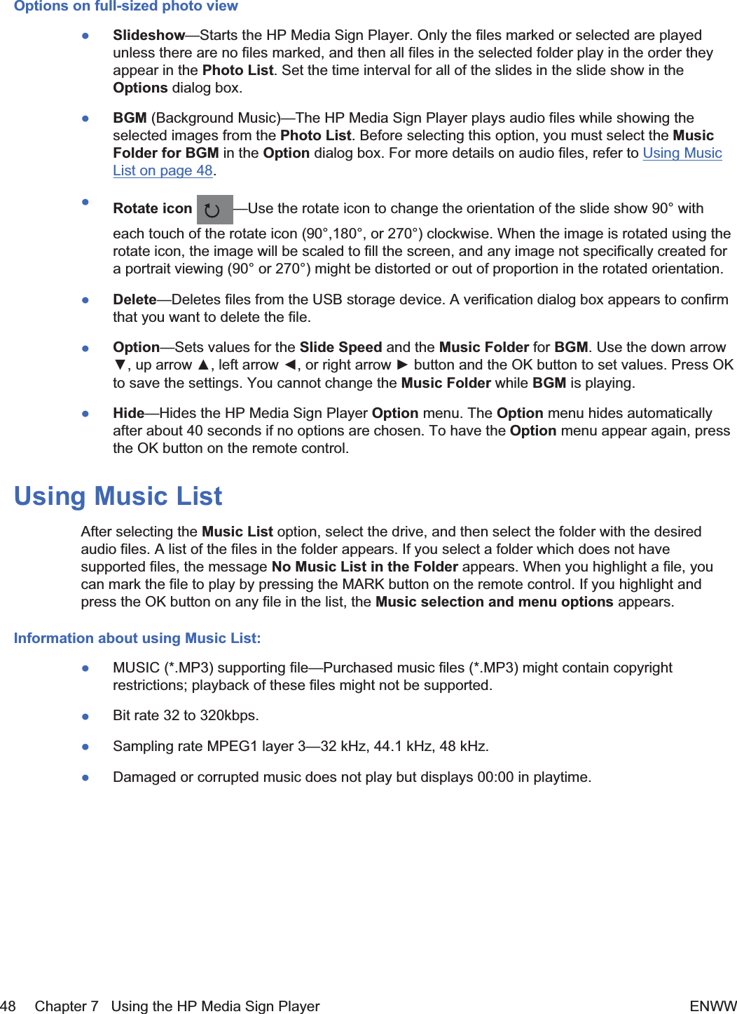
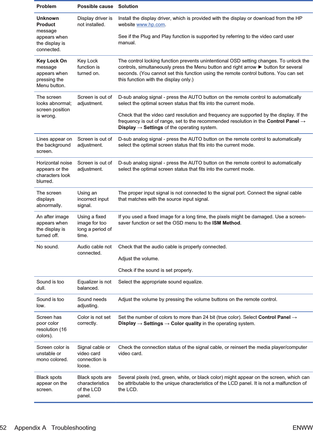
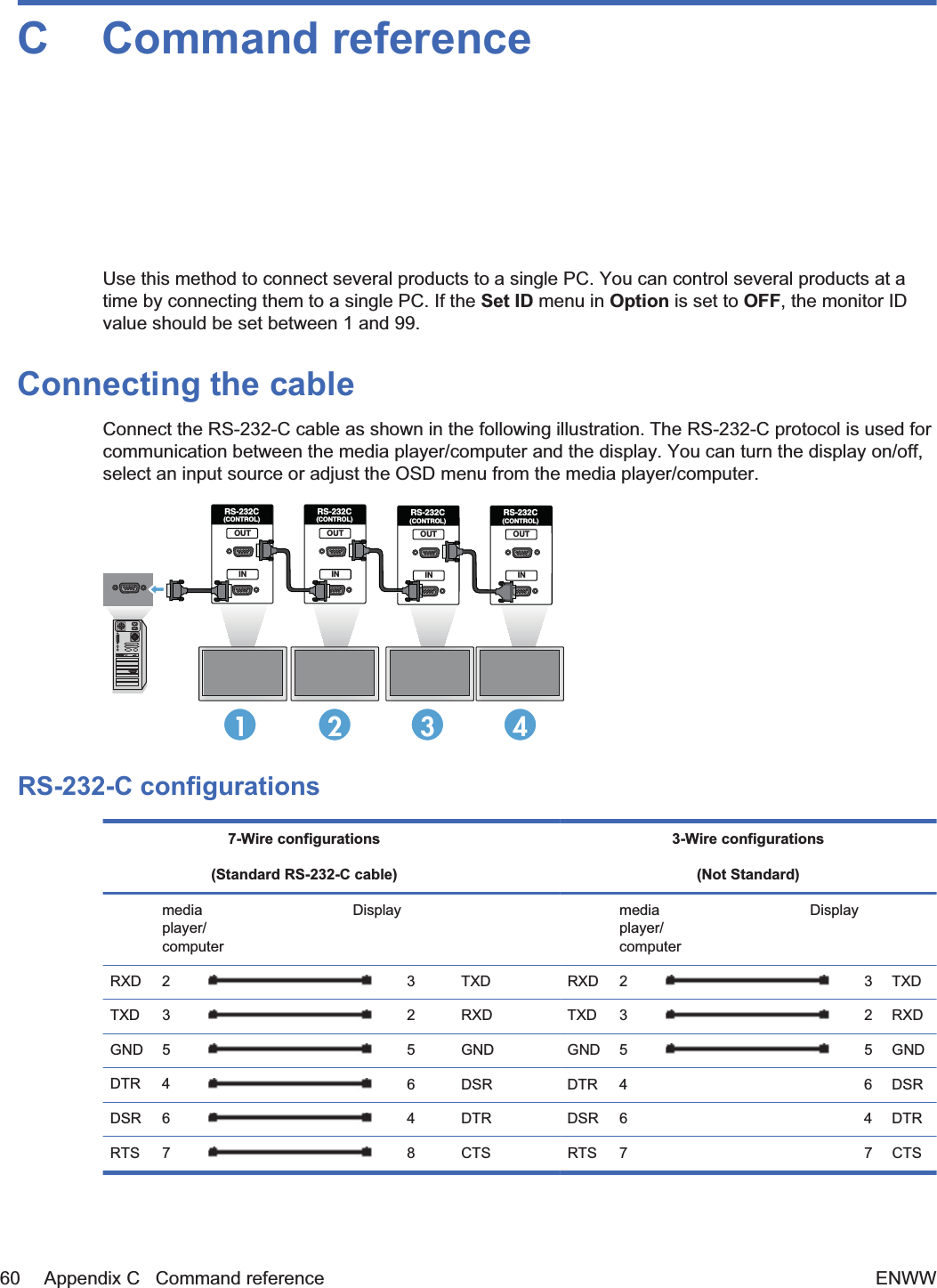
![01. Power (Command: a)To control Power On/Off of the Set.Transmission[k][a][][Set ID][][Data][Cr][Data] 0: Power Off1: Power OnAcknowledgement[a][][Set ID][][OK][Data][x]To show the status of Power On/Off.Transmission[k][a][][Set ID][][FF][Cr]Acknowledgement[a][][Set ID][][OK][Data][x][Data] 0: Power Off1: Power On64 Appendix C Command reference ENWW](https://usermanual.wiki/LG-Electronics-USA/HSTND-3411-G/User-Guide-1487016-Page-75.png)
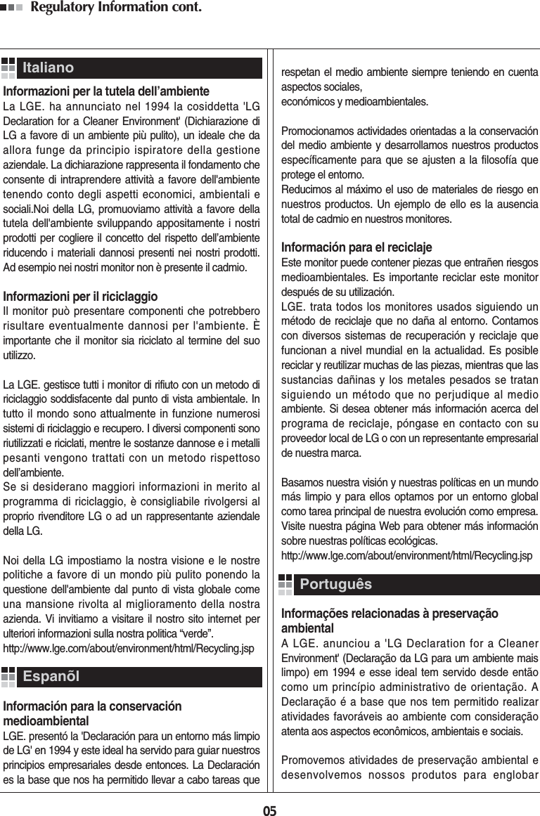
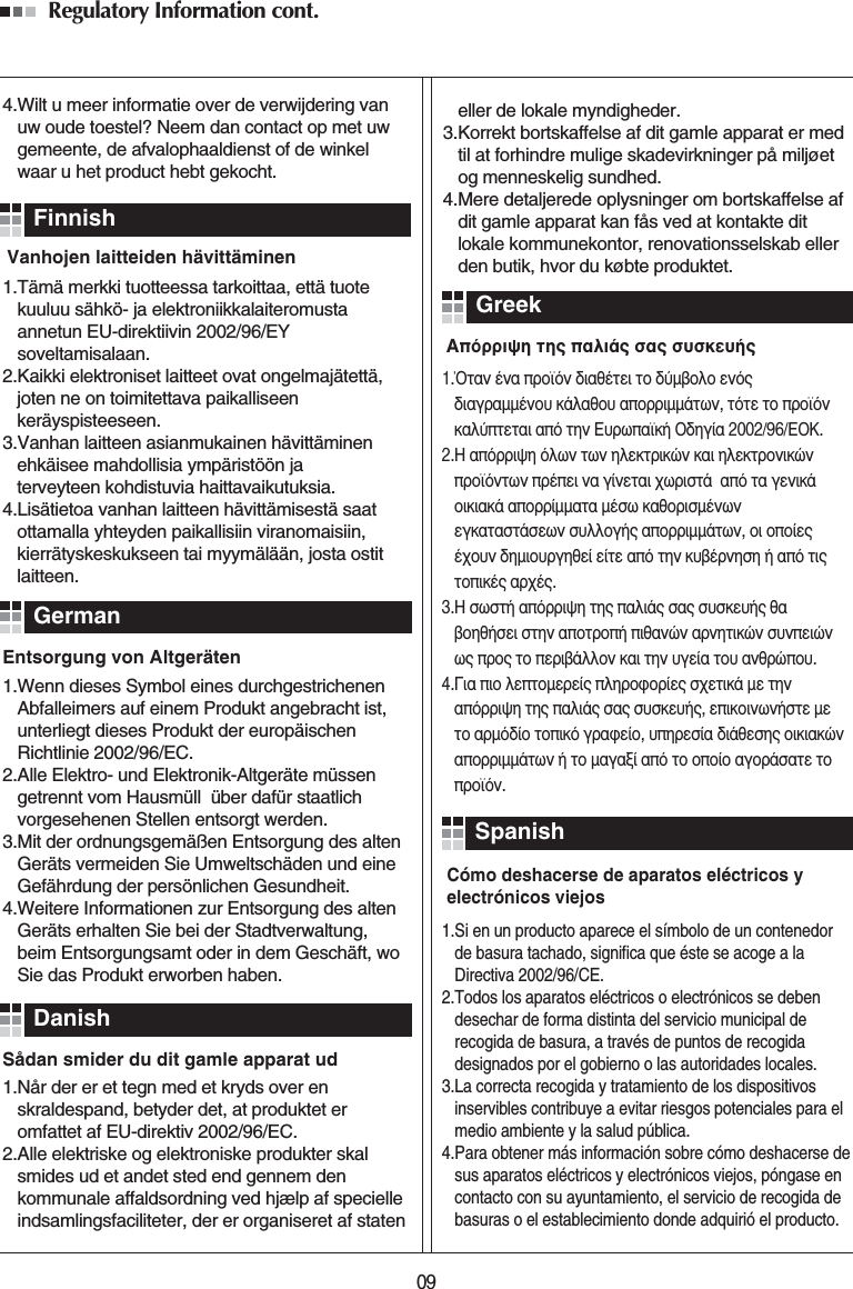
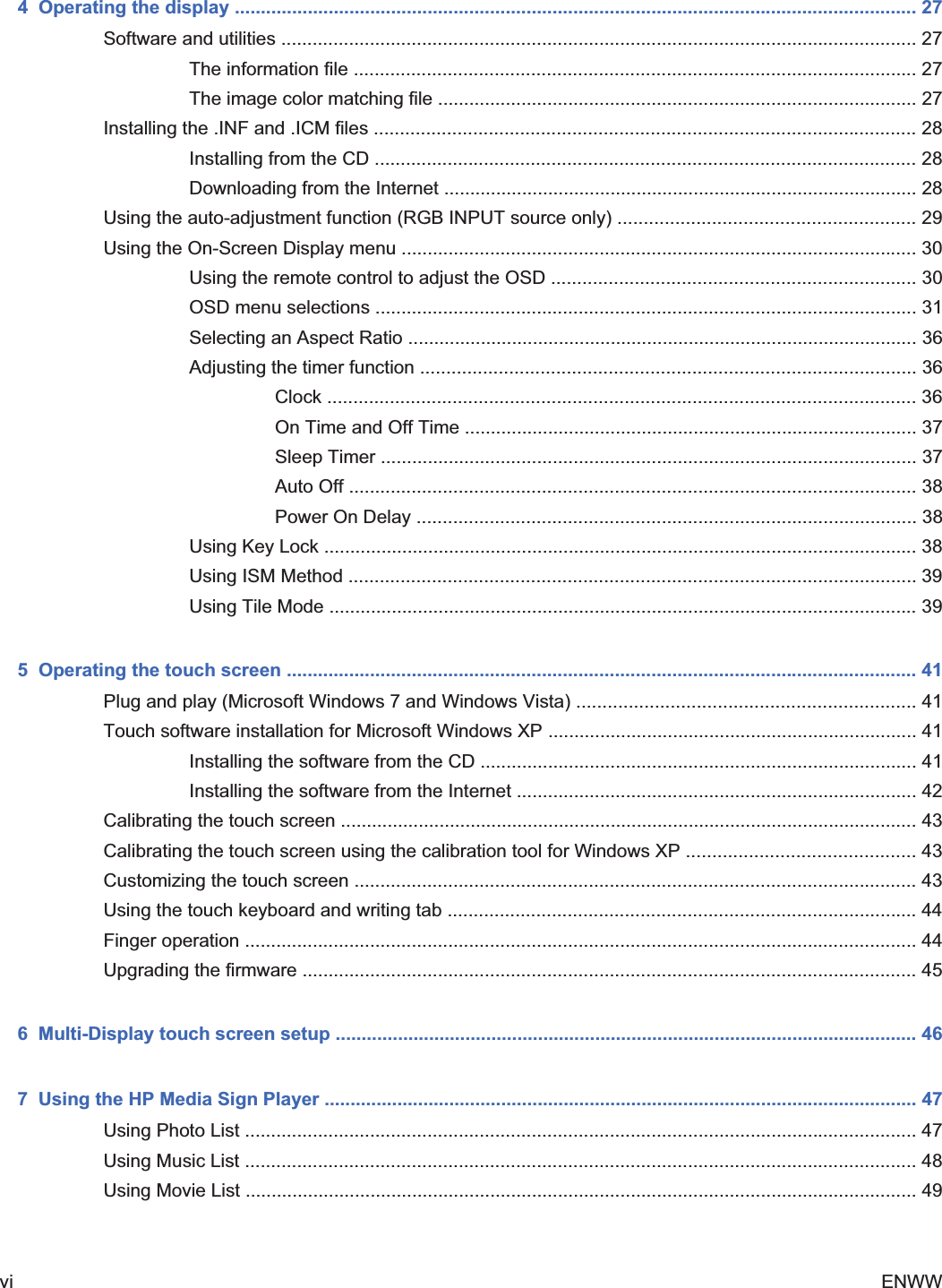
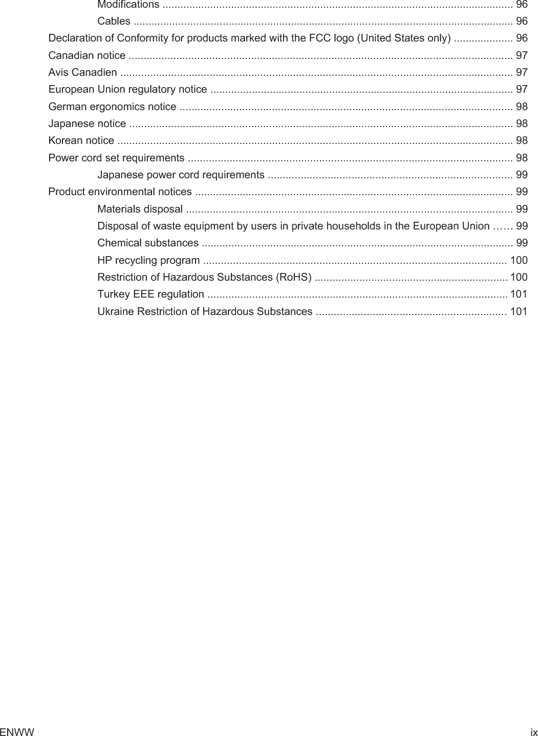
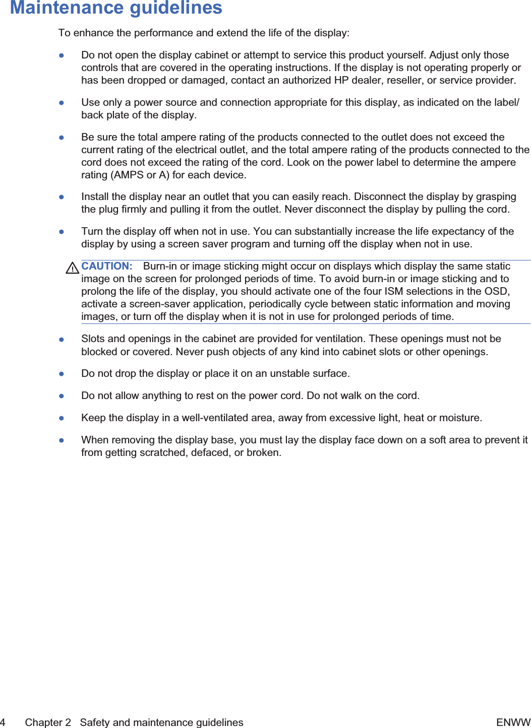
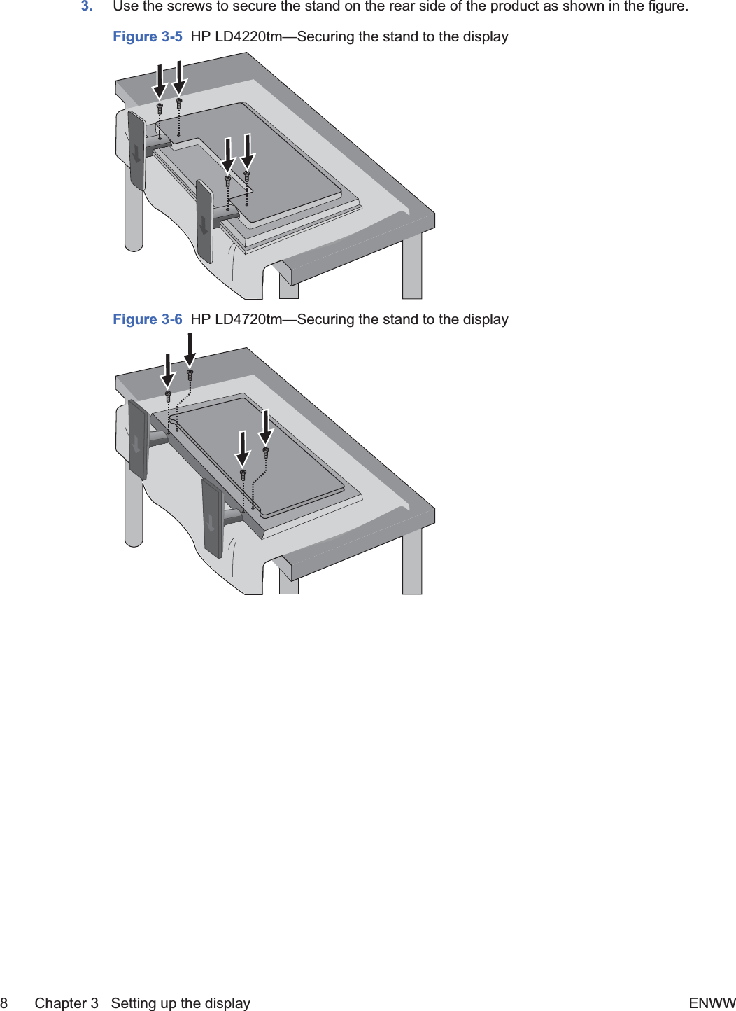
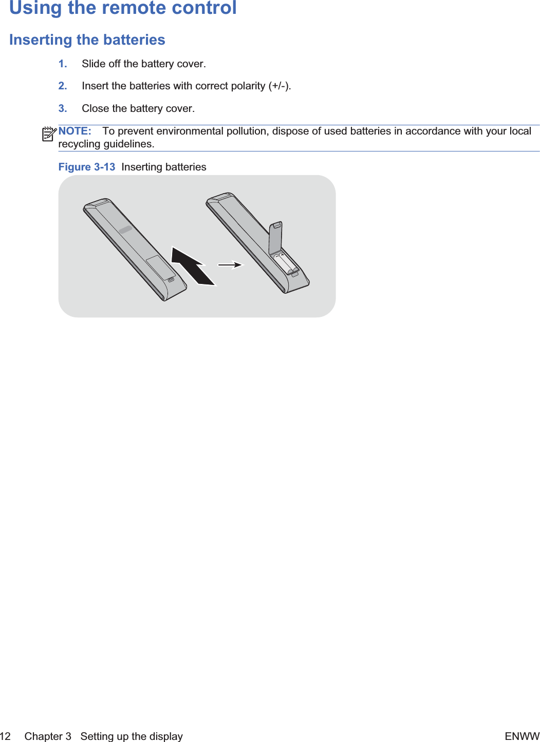
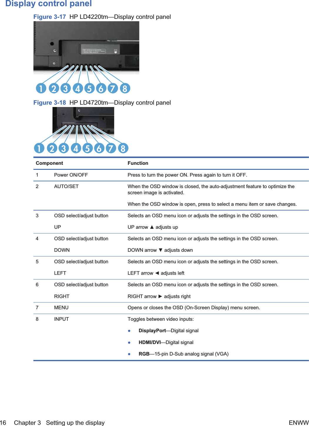
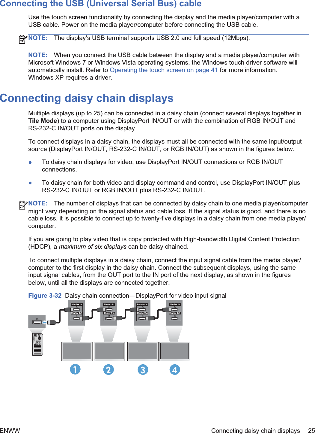
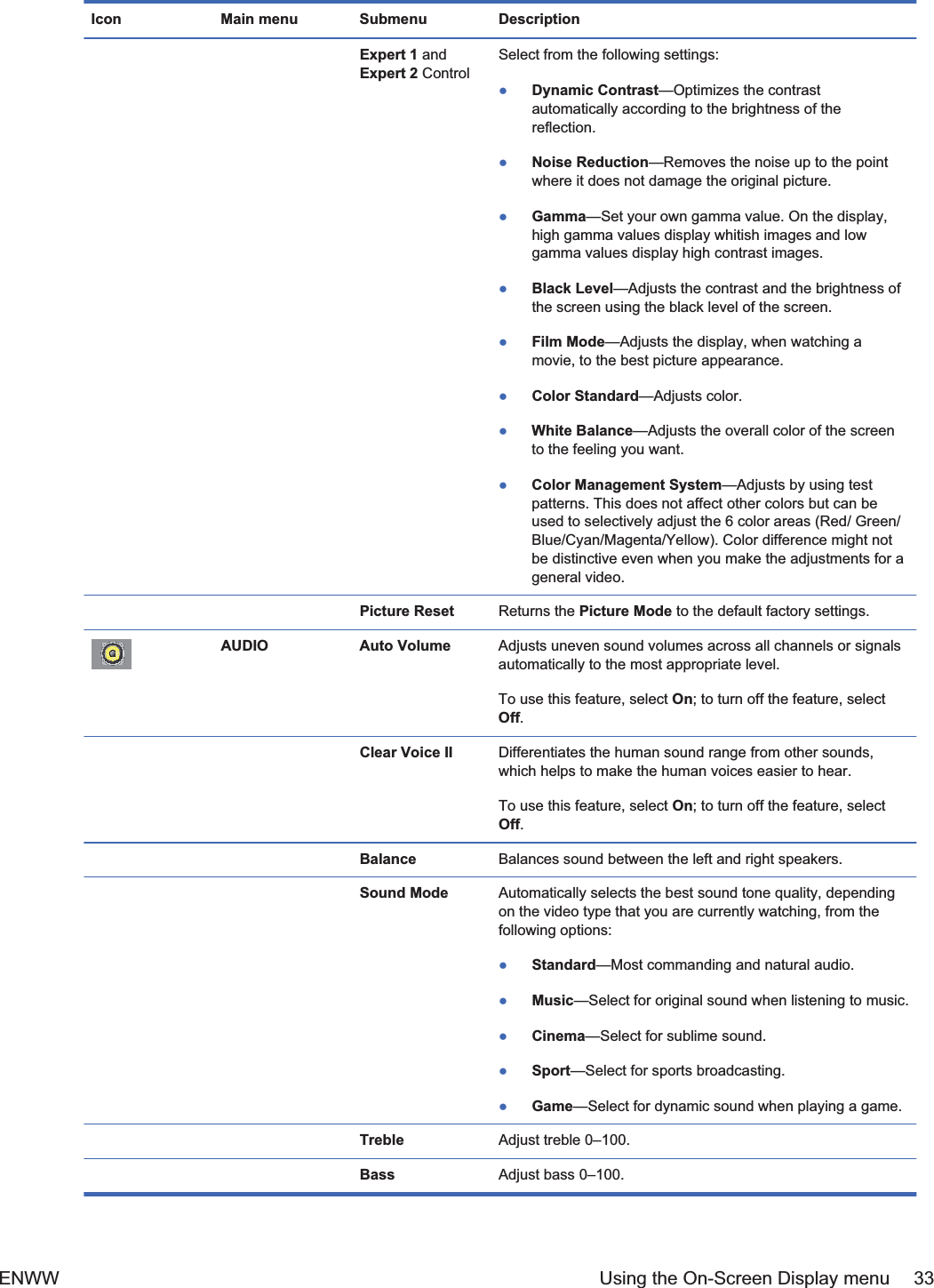
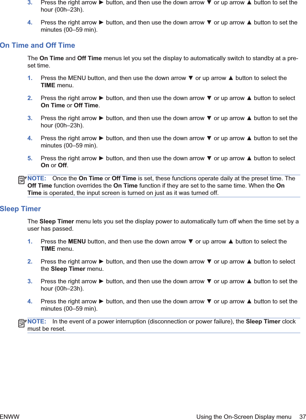
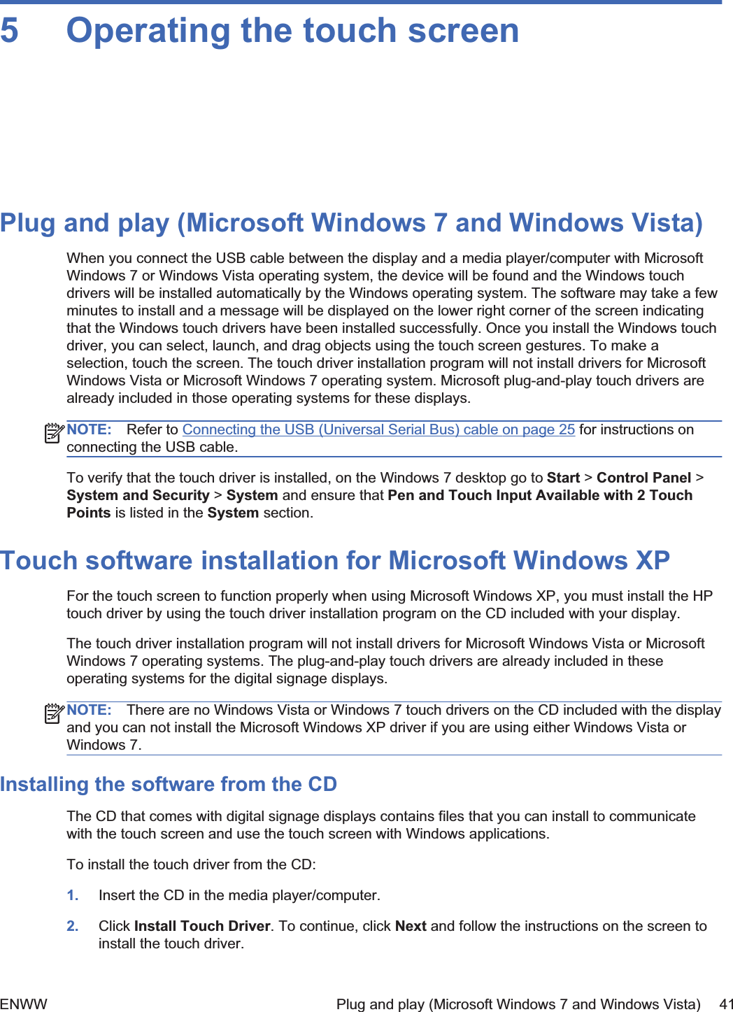
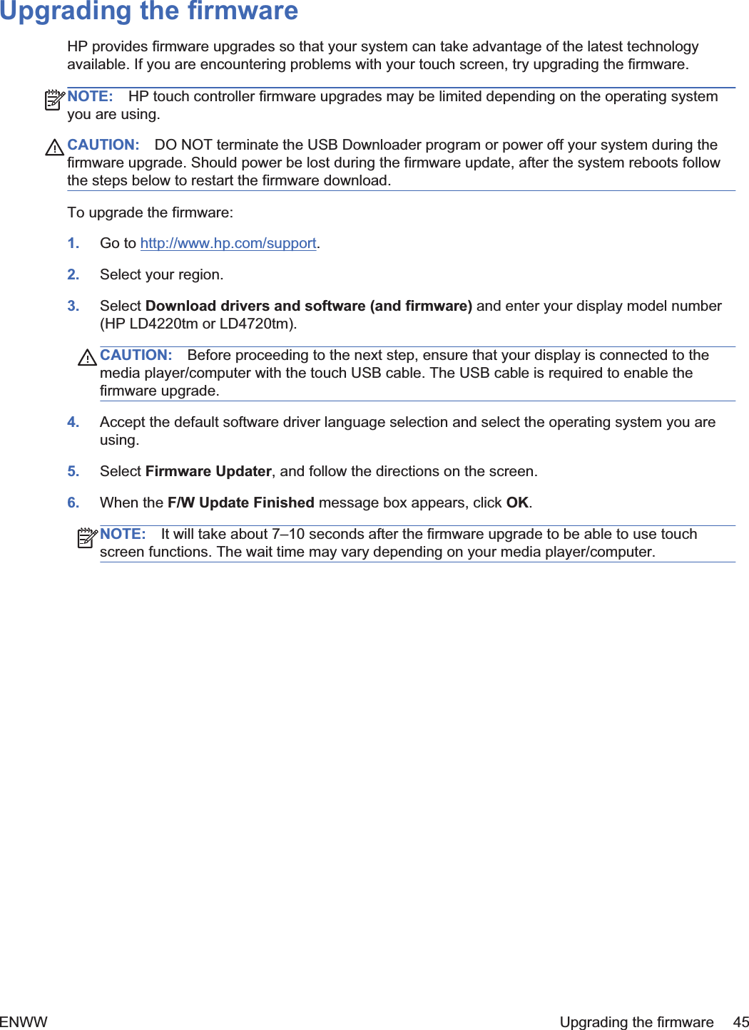
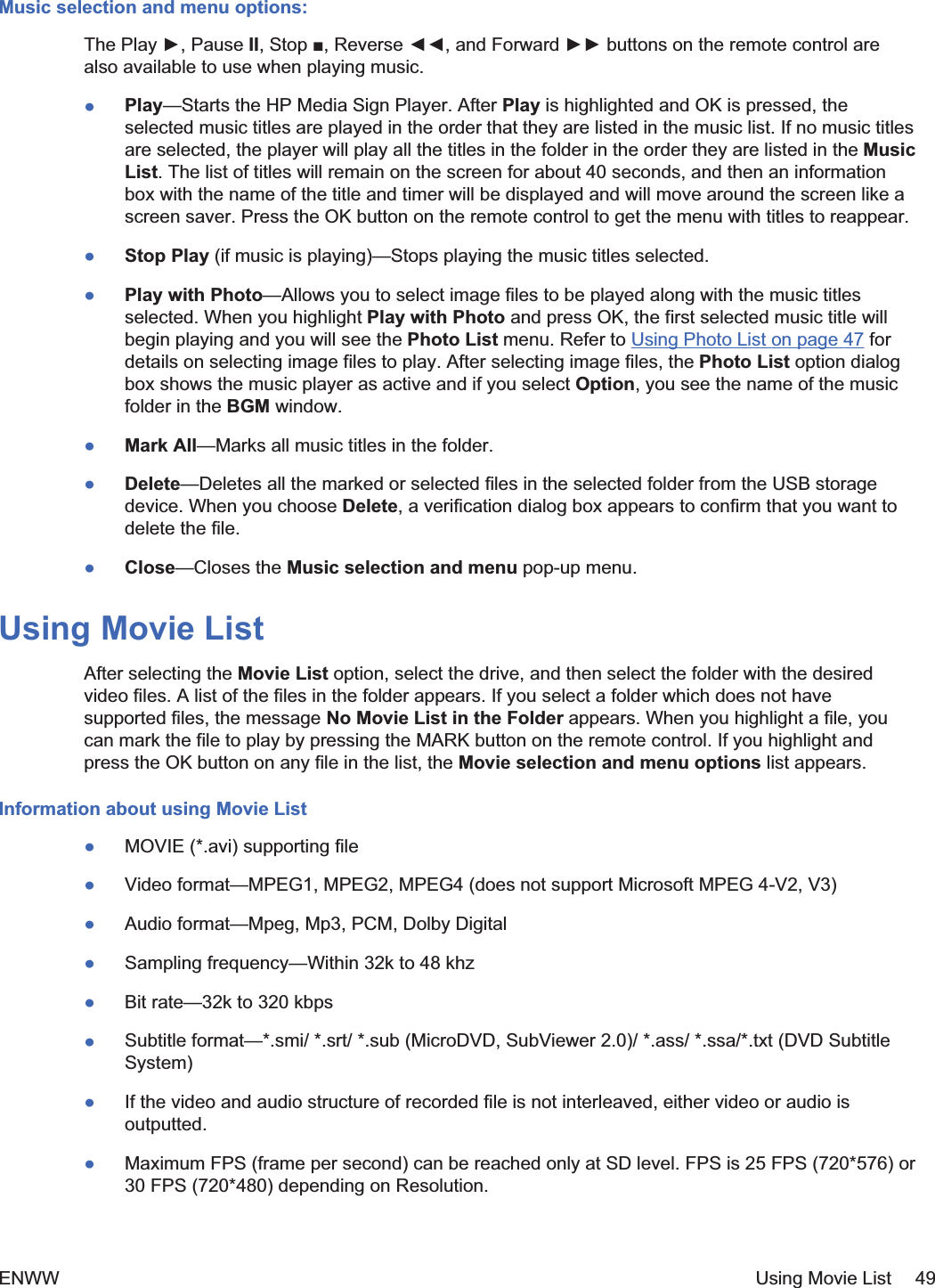
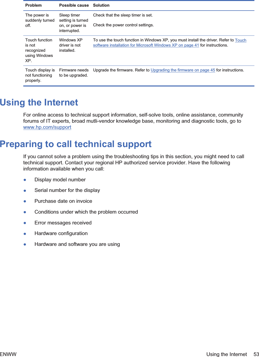
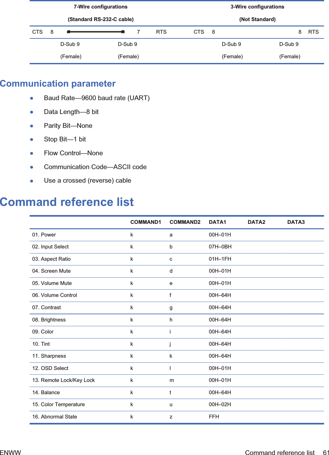
![02. Input Select (Command: b) (Main Picture Input)To select input source for the Set.You can also select an input source using the INPUT button on the remote control.Transmission[k][b][][Set ID][][Data][Cr][Data] 7: RGB (PC)8: HDMI/DVI (HD-DVD)9: HDMI (PC)A: DisplayPort (HD-DVD)B: DisplayPort (PC)Acknowledgement[b][][Set ID][][OK][Data][x][Data] 7: RGB (PC)8: HDMI/DVI (HD-DVD)9: HDMI (PC)A: DisplayPort (HD-DVD)B: DisplayPort (PC)ENWW Transmission/Receiving Protocol 65](https://usermanual.wiki/LG-Electronics-USA/HSTND-3411-G/User-Guide-1487016-Page-76.png)
![03. Aspect Ratio (Command: c) (Main picture format)To adjust the screen format.You can also adjust the screen format using the ARC (Aspect Ratio Control) button on remote controlor in the Screen menu.Transmission[k][c][][Set ID][][Data][Cr][Data] 1: Normal Screen (4:3)2: Wide Screen (16:9)4: Zoom [HDMI (HD-DVD), DisplayPort (HD-DVD)]6: Original7: 14:9 [HDMI (HD-DVD), DisplayPort (HD-DVD)]9: Just Scan [HDMI (HD-DVD), DisplayPort(HD-DVD)]When the RGB, HDMI/DVI-PC, DisplayPort-PCmode (1:1)10 to 1F: Cinema Zoom 1 to 16 [HDMI (HD-DVD), DisplayPort (HD-DVD)]Acknowledgement[c][][Set ID][][OK][Data][x]04. Screen Mute (Command: d)To select screen mute on/off.Transmission[k][d][][Set ID][][Data][Cr][Data] 0: Screen mute off (Picture on)1: Screen mute on (Picture off)Acknowledgement66 Appendix C Command reference ENWW](https://usermanual.wiki/LG-Electronics-USA/HSTND-3411-G/User-Guide-1487016-Page-77.png)
![[d][][Set ID][][OK][Data][x]05. Volume Mute (Command: e)To control On/Off of the Volume Mute.Transmission[k][e][][Set ID][][Data][Cr][Data] 0: Volume Mute On (Volume Off)1: Volume Mute Off (Volume On)Acknowledgement[e][][Set ID][][OK][Data][x][Data] 0: Volume Mute On (Volume Off)1: Volume Mute Off (Volume On)06. Volume Control (Command: f)To adjust Volume.Transmission[k][f][][Set ID][][Data][Cr][Data] Min: 00H to Max: 64H(Hexadecimal code)Acknowledgement[f][][Set ID][][OK][Data][x][Data] Min: 00H to Max: 64HENWW Transmission/Receiving Protocol 67](https://usermanual.wiki/LG-Electronics-USA/HSTND-3411-G/User-Guide-1487016-Page-78.png)
![Real data mapping 0: Step 0:A: Step 10:F: Step 1510: Step 16:64: Step 10007. Contrast (Command: g)To adjust screen contrast. You can also adjust the contrast in the Picture menu.Transmission[k][g][][Set ID][][Data][Cr][Data] Min: 00H to Max: 64HAcknowledgement[g][][Set ID][][OK][Data][x]Real data mapping 0: Step 0:A: Step 10:F: Step 1510: Step 16:64: Step 10068 Appendix C Command reference ENWW](https://usermanual.wiki/LG-Electronics-USA/HSTND-3411-G/User-Guide-1487016-Page-79.png)
![08. Brightness (Command: h)To adjust screen brightness. You can also adjust the brightness in the Picture menu.Transmission[k][h][][Set ID][][Data][Cr][Data] Min: 00H to Max: 64HRefer to “Real data mapping” as shown below.Acknowledgement[h][][Set ID][][OK][Data][x]Real data mapping 0: Step 0:A: Step 10:F: Step 1510: Step 16:64: Step 10009. Color (Command: i) (Video Timing only)To adjust the screen color. You can also adjust the color in the Picture menu.Transmission[k][i][][Set ID][][Data][Cr][Data] Min: 00H to Max: 64H(Hexadecimal code)ENWW Transmission/Receiving Protocol 69](https://usermanual.wiki/LG-Electronics-USA/HSTND-3411-G/User-Guide-1487016-Page-80.png)
![Real data mapping 0: Step 0:A: Step 10:F: Step 1510: Step 16:64: Step 100Acknowledgement[i][][Set ID][][OK][Data][x][Data] Min: 00H to Max: 64H(Hexadecimal code)10. Tint (Command: j) (Video Timing only)To adjust the screen tint. You can also adjust the tint in the Picture menu.Transmission[k][j][][Set ID][][Data][Cr][Data] Red: 00H to Green: 64H(Hexadecimal code)Real data mapping 0: Step 0:A: Step 10:F: Step 1510: Step 16:64: Step 10070 Appendix C Command reference ENWW](https://usermanual.wiki/LG-Electronics-USA/HSTND-3411-G/User-Guide-1487016-Page-81.png)
![Acknowledgement[j][][Set ID][][OK][Data][x][Data] Red: 00H to Green: 64HTint real data mapping 0: Step 0 to Red:64: Step 100 to Green11. Sharpness (Command: k) (Video Timing only)To adjust the screen Sharpness. You can also adjust the sharpness in the Picture menu.Transmission[k][k][][Set ID][][Data][Cr][Data] Min: 00H to Max: 64H(Hexadecimal code)Real data mapping 0: Step 0:A: Step 10:F: Step 1510: Step 16:64: Step 100Acknowledgement[k][][Set ID][][OK][Data][x][Data] Min: 00H to Max: 64HENWW Transmission/Receiving Protocol 71](https://usermanual.wiki/LG-Electronics-USA/HSTND-3411-G/User-Guide-1487016-Page-82.png)
![12. OSD Select (Command: l)To control OSD on/off to the set.Transmission[k][l][][Set ID][][Data][Cr][Data] 0: OSD Off1: OSD OnAcknowledgement[l][][Set ID][][OK][Data][x][Data] 0: OSD Off1: OSD On13. Remote Lock/Key Lock (Command: m)To control Remote Lock on/off to the set.This function, when controlling RS-232C, locks the remote control and the local keys.Transmission[k][m][][Set ID][][Data][Cr][Data] 0: Off1: OnAcknowledgement[m][][Set ID][][OK][Data][x][Data] 0: Off1: On72 Appendix C Command reference ENWW](https://usermanual.wiki/LG-Electronics-USA/HSTND-3411-G/User-Guide-1487016-Page-83.png)
![14. Balance (Command: t)To adjust the sound balance.Transmission[k][t][][Set ID][][Data][Cr][Data] Min: 00H to Max: 64H(Hexadecimal code)00H: Step L5064H: Step R50Acknowledgement[t][][Set ID][][OK][Data][x][Data] Min: 00H to Max: 64H00H: Step 0 to L5064H: Step 100 to R50Balance: L50 to R5015. Color Temperature (Command: u)To adjust the screen color temperature.Transmission[k][u][][Set ID][][Data][Cr][Data] 0: Medium1: Cool2: WarmAcknowledgement[u][][Set ID][][OK][Data][x]ENWW Transmission/Receiving Protocol 73](https://usermanual.wiki/LG-Electronics-USA/HSTND-3411-G/User-Guide-1487016-Page-84.png)
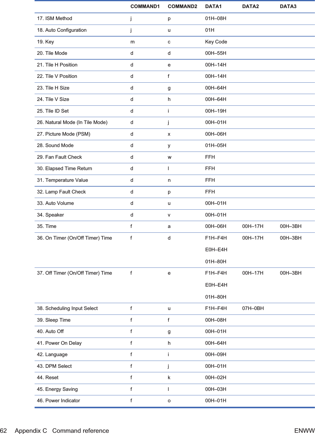
![[Data] 0: Medium1: Cool2: Warm16. Abnormal state (Command: z)Abnormal State: Used to Read the power off status when Stand-by mode.Transmission[k][z][][Set ID][][Data][Cr][Data] FF: ReadAcknowledgement[z][][Set ID][][OK][Data][x][Data] 0: Normal (Power on and signal exist)1: No signal (Power on)2: Turn the display off by remote control3: Turn the display off by sleep time function4: Turn the display off by RS-232-C function8: Turn the display off by off time function9: Turn the display off by auto off function17. ISM Method (Command: j p)Used to select the afterimage preventing function.Transmission[j][p][][Set ID][][Data][Cr]74 Appendix C Command reference ENWW](https://usermanual.wiki/LG-Electronics-USA/HSTND-3411-G/User-Guide-1487016-Page-85.png)
![[Data] 1H: Inversion2H: Orbiter4H: White Wash8H: NormalAcknowledgement[p][][Set ID][][OK][Data][x]18. Auto Configure (Command: j u)To adjust picture position and minimize image shaking automatically. It works only in RGB (PC)mode.Transmission[j][u][][Set ID][][Data][Cr][Data] 1: To setAcknowledgement[u][][Set ID][][OK][Data][x]19. Key (Command: m c)To send IR remote key code.Transmission[m][c][][Set ID][][Data][Cr]Data Key code: Refer to the IR Codes Table on page 93 section.Acknowledgement[c][][Set ID][][OK][Data][x]ENWW Transmission/Receiving Protocol 75](https://usermanual.wiki/LG-Electronics-USA/HSTND-3411-G/User-Guide-1487016-Page-86.png)
![20. Tile Mode (Command: d d)Change a Tile Mode.Transmission[d][d][][Set ID][][Data][x][Data] Description00 or 11 Tile mode is off.12 1 x 2 mode (column x row)13 1 x 3 mode14 1 x 4 mode... ...55 5 x 5 modeThe [Data] cannot be set to 0X or X0 except 00.Acknowledgement[d][][00][][OK/NG][Data][x]21. Tile H Position (Command: d e)To set the Horizontal position.Transmission[d][e][][Set ID][][Data][x][Data] Min: 00H to Max: 14H00H: Step -10 (Left)14H: Step 10 (Right)Acknowledgement[e][][Set ID][][OK/NG][Data][x]76 Appendix C Command reference ENWW](https://usermanual.wiki/LG-Electronics-USA/HSTND-3411-G/User-Guide-1487016-Page-87.png)
![22. Tile V Position (Command: d f)To set the Vertical position.Transmission[d][f][][Set ID][][Data][x][Data] Min: 00H to Max: 14H00H: Step -10 (Left)14H: Step 10 (Right)Acknowledgement[f][][Set ID][][OK/NG][Data][x]23. Tile H Size (Command: d g)To set the Horizontal size.Transmission[d][g][][Set ID][][Data][x][Data] Min: 00H to Max: 64HReal data mapping 0: Step 0:A: Step 10:F: Step 1510: Step 16:64: Step 100Acknowledgement[g][][Set ID][][OK/NG][Data][x]ENWW Transmission/Receiving Protocol 77](https://usermanual.wiki/LG-Electronics-USA/HSTND-3411-G/User-Guide-1487016-Page-88.png)
![24. Tile V Size (Command: d h)To set the Vertical size.Transmission[d][h][][Set ID][][Data][x][Data] Min: 00H to Max: 64HReal data mapping 0: Step 0:A: Step 10:F: Step 1510: Step 16:64: Step 100Acknowledgement[h][][Set ID][][OK/NG][Data][x]25. Tile ID Set (Command: d i)To assign the Tile ID for Tiling function.Transmission[d][i][][Set ID][][Data][x][Data] Min: 00H to Max: 19H(Hexadecimal code)Acknowledgement[i][][Set ID][][OK/NG][Data][x]78 Appendix C Command reference ENWW](https://usermanual.wiki/LG-Electronics-USA/HSTND-3411-G/User-Guide-1487016-Page-89.png)
![26. Natural Mode (In Tile Mode) (Command: d j)To assign the Title Natural mode for Tiling function.Transmission[d][j][][Set ID][][Data][x][Data] 0: Natural Off1: Natural Onff: Read StatusAcknowledgement[j][][Set ID][][OK/NG][Data][x]27. Picture Mode (Command: d x)To adjust the picture mode.Transmission[d][x][][Set ID][][Data][x]Data StructureData (Hex) MODE00 Vivid01 Standard02 Cinema03 Sport04 Game05 Expert 106 Expert 2Acknowledgement[x][][Set ID][][OK/NG][Data][x]ENWW Transmission/Receiving Protocol 79](https://usermanual.wiki/LG-Electronics-USA/HSTND-3411-G/User-Guide-1487016-Page-90.png)
![28. Sound Mode (Command: d y )To adjust the Sound mode.Transmission[d][y][][Set ID][][Data][X]Data StructureData (Hex) MODE01 Standard02 Music03 Cinema04 Sport05 GameAcknowledgement[y][][Set ID][][OK/NG][Data][x]29. Fan Fault check (Command: d w )To check the Fan fault of the display.Transmission[d][w][][Set ID][][Data][x][Data] Data is always FF (in Hex)Data ff: Read StatusAcknowledgement[w][][Set ID][][OK/NG][Data][x]80 Appendix C Command reference ENWW](https://usermanual.wiki/LG-Electronics-USA/HSTND-3411-G/User-Guide-1487016-Page-91.png)
![[Data] [Data] is the status value of the Fan fault.0: Fan fault1: Fan OK2: N/A (Not Available)30. Elapsed time return (Command: d l)To read the elapsed time.Transmission[d][l][][Set ID][][Data][x][Data] Data is always FF (in Hex)Acknowledgement[l][][Set ID][][OK/NG][Data][x][Data] The data means used hours.(Hexadecimal code)31. Temperature value (Command: d n)To read the inside temperature value.Transmission[d][n][][Set ID][][Data][x][Data] Data is always FF (in Hex)Acknowledgement[n][][Set ID][][OK/NG][Data][x][Data] The data is 1 byte long in Hexadecimal.ENWW Transmission/Receiving Protocol 81](https://usermanual.wiki/LG-Electronics-USA/HSTND-3411-G/User-Guide-1487016-Page-92.png)
![32. Lamp fault Check (Command: d p)To check lamp fault.Transmission[d][p][][Set ID][][Data][x][Data] Data is always FF (in Hex)Acknowledgement[p][][Set ID][][OK/NG][Data][x][Data] 0: Lamp Fault1: Lamp OK2: N/A(DPM/Power Off)33. Auto volume (Command: d u)Automatically adjust the volume level.Transmission[d][u][][Set ID][][Data][x][Data] 0: Off1: OnAcknowledgement[u][][Set ID][][OK/NG][Data][x]82 Appendix C Command reference ENWW](https://usermanual.wiki/LG-Electronics-USA/HSTND-3411-G/User-Guide-1487016-Page-93.png)
![34. Speaker (Command: d v)Turn the speaker on or off.Transmission[d][v][][Set ID][][Data][x][Data] 0: Off1: OnAcknowledgement[v][][Set ID][][OK/NG][Data][x]35. Time (Command: f a)Set the current time.Transmission[f][a][][Set ID][][Data1][][Data2][][Data3][Cr][Data1] 0: Monday1: Tuesday2: Wednesday3: Thursday4: Friday5: Saturday6: Sunday[Data2] 00H to 17H (Hours)[Data3] 00H to 3BH (Minutes)Acknowledgement[a][][Set ID][][OK/NG][Data1][Data2][Data3][x]ENWW Transmission/Receiving Protocol 83](https://usermanual.wiki/LG-Electronics-USA/HSTND-3411-G/User-Guide-1487016-Page-94.png)
![When reading data, FFH is inputted for [Data1], [Data2] and [Data3]. In other cases, all are treated asNG.36. On Timer (On/Off Timer) Time (Command: f d)Set On Timer.Transmission[f][d][][Set ID][][Data1][][Data2][][Data3][Cr] 1. 2. 3.[Data1] f1h to f4h (read one index) e0h to e4h (delete one index),e0h (delete all indexes)01h to 80h (write) (Day of Week)f1: read 1st index of On TimeListe0: delete all indexes of On TimeListbit0 (01h): Mondayf2: read 2nd index of On TimeListe1: delete 1st index of On TimeListbit1 (02h): Tuesdayf3: read 3rd index of On TimeListe2: delete 2nd index of On TimeListbit2 (04h): Wednesdayf4: read 4th index of On TimeListe3: delete 3rd index of On TimeListbit3 (08h): Thursdaybit4 (10h): Fridaye4: delete 4th index of On TimeListbit5 (20h): Saturdaybit6 (40h): Sundaybit7 (80h): Everyday(1fh): Monday to Friday(3fh): Monday to Saturday(60h): Saturday to Sunday[Data2] 00h to 17h, ffh (Hours)[Data3] 00h to 3bh, ffh (Minutes)When you read/delete the current on time list, all of [Data2][Data3] have to be 0xff.ex1: fd 01 f1 ff ff - when you read 1st index of On Time Listex2: fd 01 e1 ff ff - when you delete 1st index of On Time Listex3: fd 01 3f 02 03 - when you write one On Time Data, "Monday to Saturday,02:03"84 Appendix C Command reference ENWW](https://usermanual.wiki/LG-Electronics-USA/HSTND-3411-G/User-Guide-1487016-Page-95.png)
![Acknowledgement[d][][Set ID][][OK][Data1][Data2][Data3][x]37. Off Timer (On/Off Timer) Time (Command: f e)Set Off Timer.Transmission[f][e][][Set ID][][Data1][][Data2][][Data3][Cr] 1. 2. 3.[Data1] f1h to f4h (read one index) e0h to e4h(delete one index),e0h (delete all indexes)01h to 80h (write) (Day of Week)f1: read 1st index of On TimeListe0: delete all indexes of On TimeListbit0 (01h): Mondayf2: read 2nd index of On TimeListe1: delete 1st index of On TimeListbit1 (02h): Tuesdayf3: read 3rd index of On TimeListe2: delete 2nd index of On TimeListbit2 (04h): Wednesdayf4: read 4th index of On TimeListe3: delete 3rd index of On TimeListbit3 (08h): Thursdaybit4 (10h): Fridaye4: delete 4th index of On TimeListbit5 (20h): Saturdaybit6 (40h): Sundaybit7 (80h): Everyday(1fh): Monday to Friday(3fh): Monday to Saturday(60h): Saturday to Sunday[Data2] 00h to 17h, ffh (Hours)ENWW Transmission/Receiving Protocol 85](https://usermanual.wiki/LG-Electronics-USA/HSTND-3411-G/User-Guide-1487016-Page-96.png)
![[Data3] 00h to 3bh, ffh (Minutes)When you read/delete the current on time list, all of [Data2][Data3] have to be 0xff.ex1: fd 01 f1 ff ff - when you read 1st index of On Time Listex2: fd 01 e1 ff ff - when you delete 1st index of On Time Listex3: fd 01 3f 02 03 - when you write one On Time Data, "Monday to Saturday,02:03"Acknowledgement[e][][Set ID][][OK][Data1][Data2][Data3][x]38. Scheduling Input select (Command: f u) (Main Picture Input)To select input source for TV depending on day.Transmission[f][u][][Set ID][][Data1][][Data2][Cr] [Data1] f1h to f4h(write/read one index)f1: read 1st index of On Time Inputf2: read 2nd index of On Time Inputf3: read 3rd index of On Time Inputf4: read 4th index of On Time Input Data (Hex) INPUT[Data2] 07 RGB-PC08 HDMI/DVI (HD-DVD)09 HDMI/DVI (PC)A DisplayPort (HD-DVD)B DisplayPort (PC)When you read/delete the current On Time Input, [Data2] needs to be 0xff.ex1: fu 01 f1 ff - when you read 1st index of On Time Inputex2: fu 01 f3 07 - when you write one On Time Input Data in to 3rd index, "RGB"86 Appendix C Command reference ENWW](https://usermanual.wiki/LG-Electronics-USA/HSTND-3411-G/User-Guide-1487016-Page-97.png)
![Acknowledgement[u][][Set ID][][OK][Data1][Data2][x]39. Sleep Time (Command: f f)Set Sleep Time.Transmission[f][f][][Set ID][][Data][Cr][Data] 0: Off1: 102: 203: 304: 605: 906: 1207: 1808: 240Acknowledgement[f][][Set ID][][OK/NG][Data][x]40. Auto Off (Command: f g)Set Auto Sleep.Transmission[f][g][][Set ID][][Data][Cr][Data] 0: Off1: OnAcknowledgementENWW Transmission/Receiving Protocol 87](https://usermanual.wiki/LG-Electronics-USA/HSTND-3411-G/User-Guide-1487016-Page-98.png)
![[g][][Set ID][][OK/NG][Data][x]41. Power On Delay (Command: f h)Set the schedule delay when the power is turned on (Unit: second).Transmission[f][h][][Set ID][][Data][Cr][Data] 00H to 64H (Data value)Real data mapping 0: Step 0:A: Step 10:F: Step 1510: Step 16:64: Step 100Acknowledgement[h][][Set ID][][OK/NG][Data][x]42. Language (Command: f i)Set the OSD language.Transmission[f][i][][Set ID][][Data][Cr]88 Appendix C Command reference ENWW](https://usermanual.wiki/LG-Electronics-USA/HSTND-3411-G/User-Guide-1487016-Page-99.png)
![[Data] 0: English1: French2: German3: Spanish4: Italian5: Portuguese6: Chinese7: Japanese8: Korean9: RussianAcknowledgement[i][][Set ID][][OK/NG][Data][x]43. DPM Select (Command: f j)Set the DPM (Display Power Management) function.Transmission[f][j][][Set ID][][Data][Cr][Data] 0: Off1: OnAcknowledgement[j][][Set ID][][OK/NG][Data][x]44. Reset (Command: f k)Execute the Picture, Screen and Factory Reset functions.Transmission[f][k][][Set ID][][Data][Cr]ENWW Transmission/Receiving Protocol 89](https://usermanual.wiki/LG-Electronics-USA/HSTND-3411-G/User-Guide-1487016-Page-100.png)
![[Data] 0: Picture Reset1: Screen Reset2: Factory ResetAcknowledgement[k][][Set ID][][OK/NG][Data][x]45. Energy saving (Command: f I)To set the Power saving mode.Transmission[f][I][][Set ID][][Data][Cr][Data] 0: Off1: (static level 1)2: (static level 2)3: (static level 3)Acknowledgement[I][][Set ID][][OK/NG][Data][x]46. Power Indicator (Command: f o)To set the LED for Power IndicatorTransmission[f][o][][Set ID][][Data][Cr][Data] 0: Off1: OnAcknowledgement[o][][Set ID][][OK/NG][Data][x]90 Appendix C Command reference ENWW](https://usermanual.wiki/LG-Electronics-USA/HSTND-3411-G/User-Guide-1487016-Page-101.png)
![47. Serial no. Check (Command: f y)To read the serial numbersTransmission[f][y][][Set ID][][Data][Cr][Data] Data FF (to read the serial numbers)Acknowledgement[y][][Set ID][][OK/NG][Data1]to[Data13][x][Data] The data format is ASCII Code.48. S/W Version (Command: f z)Check the software version.Transmission[f][z][][Set ID][][Data][Cr][Data] FFH: ReadAcknowledgement[z][][Set ID][][OK/NG][Data][x]49. Input Select (Command: x b)To select input source for the display.Transmission[x][b][][Set ID][][Data][Cr]ENWW Transmission/Receiving Protocol 91](https://usermanual.wiki/LG-Electronics-USA/HSTND-3411-G/User-Guide-1487016-Page-102.png)
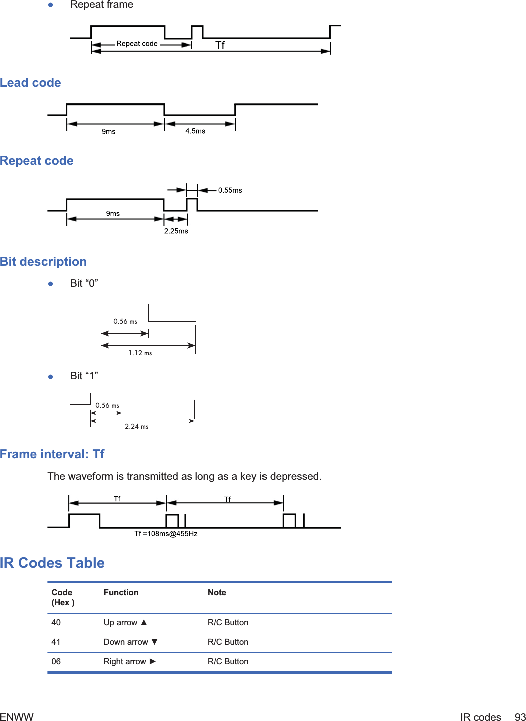
![[Data] 60H: RGB (PC)90H: HDMI/DVI (HD-DVD)A0H: HDMI/DVI (PC)B0H: DisplayPort (HD-DVD)C0H: DisplayPort (PC)Acknowledgement[b][][Set ID][][OK][Data][x][Data] 60H: RGB (PC)90H: HDMI/DVI (HD-DVD)A0H: HDMI/DVI (PC)B0H: DisplayPort (HD-DVD)C0H: DisplayPort (PC)IR codesUse this method to connect your wired remote control port on the display.Remote Control IR CodeOutput waveformłSingle pulse, modulated with 37.917kHz signal at 455kHzłCarrier FrequencyŃFCAR = 1/Tc=fosc/12ŃDuty Ratio = T1/Tc = 1/3Configuration of frameł1st frame92 Appendix C Command reference ENWW](https://usermanual.wiki/LG-Electronics-USA/HSTND-3411-G/User-Guide-1487016-Page-103.png)