LG Electronics USA L01G Cellular/PCS GSM and Cellular WCDMA Wireless Router with WLAN User Manual
LG Electronics MobileComm USA, Inc. Cellular/PCS GSM and Cellular WCDMA Wireless Router with WLAN Users Manual
Users Manual

Contents/Precautions
Setting Up
Connecting to the Internet
Settings (Web browser)
Settings (setting menu on this terminal)
Overseas Use
Charging Mobile Devices
Appendix/Troubleshooting
Before Using this terminal
ISSUE DATE:
NAME:
PHONE NUMBER:
MAIL ADDRESS:
INSTRUCTION MANUAL
‘14.X
L-01G

Introduction
Thank you for purchasing L-01G.
Before or while using, read this manual thoroughly to ensure you use correctly.
Operation description
Download the latest information of this manual from DOCOMO website.
■ "L-01G Setting Up Manual" (Japanese) (Supplied accessory)
It describes how to connect this terminal with PC, etc.
■ "L-01G INSTRUCTION MANUAL" (this manual)
Details about functions and operations are explained.
Download from DOCOMO website.
http://www.nttdocomo.co.jp/english/support/trouble/manual/download/index.html
※ The URL, as well as the contents are subject to change without prior notice.
1
Contents/Precautions
Supplied Accessories
About other optional accessories and related
equipment → P132
L-01G Terminal (with
warranty)
Back Cover LXX
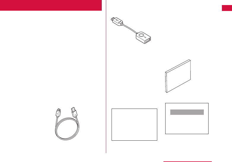
USB Cable L03
Converter Cable for
Charging L02
Battery Pack LXX L-01G INSTRUCTION
MANUAL (Japanese)
取扱説明書
L-01G Setting Up
Manual (Japanese)
かんたんセットアップマニュア ル
SSID/Security sticker
SSID: L01G_XXXXXXXX_A
Security Key: XXXXXXXX
XXXXXXXXXXXXXXX
※XXXXXXXXXXXXXXX※

2
Contents/Precautions
How to Read this Manual
• Any reprint of this manual is prohibited.
• This manual is subject to change without prior
notice.
• Please note that "this terminal" indicates "L-01G"
in this manual.
• In this manual, the operations are described by
illustrations and marks to ensure the correct
usage of this terminal.
• Images and illustrations used in this manual
may diff er from the real images displayed on this
terminal or diff er from the real product.
• Please note that "PC" indicates both "Windows"
and "Mac" in this manual.

3
Contents/Precautions
Supplied Accessories ………………………………… 1
How to Read this Manual……………………………… 2
About Usage of this Terminal ……………………… 5
Main Functions …………………………………………… 7
Safety Precautions (ALWAYS FOLLOW THESE
PRECAUTIONS)
…………………………………………… 10
Handling and Care …………………………………… 25
Before Using this Terminal …………… 31
Part Names and Functions ………………………… 31
Using docomo mini UIM card ……………………… 33
Attaching/Removing Battery Pack ……………… 36
Charging ………………………………………………… 39
Power On/Of …………………………………………… 42
Viewing Display ……………………………………… 44
Basic Operations ……………………………………… 46
Entering a Character ………………………………… 47
Setting up ………………………………… 49
Setup …………………………………………………… 49
Setup Flow ……………………………………………… 52
For Wire Connection ………………………………… 53
For Wireless Connection …………………………… 62
Setting Each Item …………………………………… 76
Connecting to the Internet …………… 77
Internet Connection ………………………………… 77
Connecting to the Internet ………………………… 77
Connecting to the Internet Using Public Wireless
LAN ……………………………………………………… 78
Settings (Web browser) ……………… 79
Logging in to the Setting Page
(L-01G Connection Manager) …………………… 79
Confi rming Connection State or Setting State of
this Terminal …………………………………………… 82
Setting Provider ……………………………………… 84
Setting Public Wireless LAN ……………………… 86
Setting Network ……………………………………… 88
Advanced Settings of Wireless LAN …………… 89
Setting Router ………………………………………… 99
Managing system …………………………………… 104
Settings (setting menu on this terminal)
… 116
Setting on the Display of this Terminal
(Setting Menu) …………………………………………116
Contents

4
Contents/Precautions
Overseas Use …………………………… 125
Overview of International Roaming
(WORLD WING) …………………………………………125
Available Services …………………………………… 125
Confi rming before Using ……………………………126
Settings for using overseas ………………………128
Charging Mobile Device ……………… 130
Charging Mobile Device ……………………………130
Appendix/Troubleshooting …………… 133
L-01G Connection Manager menu item setting
item list …………………………………………………133
Introduction of Options and Related Devices …141
Troubleshooting ………………………………………142
Error message …………………………………………149
Warranty and After-Sales Service ………………151
Updating Software ……………………………………153
Resetting this Terminal ……………………………156
Main Specifi cations ………………………………… 157
Export Administration Regulations ………………160
Declaration of Conformity …………………………161
Important Safety Information ………………………162
Intellectual Property Right …………………………165
Unlocking SIM …………………………………………166
Index ………………………………………………………167

5
Contents/Precautions
About Usage of this
Terminal
• This terminal supports LTE, W-CDMA, GSM/
GPRS and wireless LAN systems.
• Since this terminal uses wireless signal, it may
not be able to use in a location with no signal
reception such as a tunnel, underground, a
building, an outdoor location with weak or poor
signal reception, or a location outside of the Xi
and FOMA service areas. Also this terminal may
not be able to use on high upper fl oors of high-
rise apartments or buildings, even if you can see
no obstructions around you. Please note that
on occasion, data communication may become
disconnected even when you are in a strong-
signal area with 4 signal bars displayed while
you are not moving.
• Note that we do not take responsibilities for any
pure economic losses caused by communication
problems due to false operations of this terminal,
or in case of power outage, etc.
• This terminal responds to FOMA Plus-Areas and
FOMA HIGH-SPEED Areas.
• This terminal uses only docomo mini UIM card.
Bring your UIM/FOMA card to a docomo Shop to
exchange it.
• Set PIN1 lock for this terminal to ensure the
security in case of the loss. (→P102)
• For the details of usage fee, view http://www.
nttdocomo.co.jp/english/
• Note that we do not guarantee any performances
of the optional accessories you purchase at
stores.
• This terminal supports Xi data communication/
FOMA data communication. You are charged
based on the communication format of
measuring sending and receiving data amount.
When using an access point compatible to
Xi data communication (LTE) or FOMA data
communication (3G), such as docomo Internet
connection service of "mopera U", speed of data
communication can reach to maximum 150
Mbps* for receiving data and maximum 50 Mbps*
for sending data.
* Only a part of Xi areas.
• Communication fee may become high when
browsing websites containing a large amount
of images, downloading a large capacity or
performing a large data communication.
• Depending on the network congestion situation,
communication speed may slow down, or it may
be diffi cult to connect network. Especially for
customers who uses a large amount of data
(1 GB or more for last three days, including the
current day), speed may slow down.

6
Contents/Precautions
• Auto access to Internet after powering on is the
default settings for this terminal. We recommend
you turn off this terminal while staying overseas.
• This terminal does not support voice call, digital
signal (TV call, 64 K data communication) and
FAX communication.
• This terminal does not support Remote Wakeup.
• Usage fee of Internet service provider
For Internet access on a PC, etc., usage fee of
docomo Xi/FOMA service contract line, together
with usage fee of Internet service provider
such as a corresponding provider "mopera U"
of docomo are charged. For information about
application of "mopera U", service contents and
setting method, view homepage of "mopera U"
(http://www.mopera.net (in Japanese only)).
You can use Internet service provider of other
companies. In that case, pay usage fee directly
to the provider you use. Consult a provider
directly about the detailed information.
• User authentication when accessing to network
Depending on the connection destination, user
authentication (ID and password) may require
while attempting access. In that case, enter ID
and password and connect.
• ID and password are granted by either Internet
service provider or the network administrator of
that access point. Consult directly for detailed
information.
• Even though the display on this terminal applies
advanced technique, part of the dots may not
light up as well as those always-on light. Please
note that this is a feature of the display. It is not
a malfunction.

7
Contents/Precautions
Main Functions
This terminal can be connected to more than
one wireless LAN terminal via wireless LAN
such as a PC or a game machine, and it can
also be connected to a PC, etc. via USB Cable.
In addition, you can access to the Internet
from the connected device using Xi data
communication or FOMA data communication
via this terminal.
Basic Operations
This terminal supports Xi data communication.
Up to 10 Wi-Fi compatible devices can be
connected to this terminal.
It is compatible with the wireless LAN standard
of IEEE802.11a/b/g/n (2.4 GHz band, 5 GHz
band)/ac. The maximum communication speed
is shown below.
• Connecting to IEEE802.11ac/maximum 867 Mbps
• Connecting to IEEE802.11n/maximum 300 Mbps
• Connecting to IEEE802.11a/g/maximum 54 Mbps
• Connecting to IEEE802.11b/maximum 11 Mbps
When accessing to the Internet, maximum 150
Mbps* for receiving/maximum 50 Mbps* for
sending.
* Only a part of Xi areas.
• For details about compatible areas, please visit
DOCOMO website.

8
Contents/Precautions
• The communication speed is the maximum
value of sending and receiving data based
on the technical standard. It is not the real
communication speed. The speed is provided by
the best eff ort method. The real communication
speed changes depending on the communication
environment and the network congestion
situation.
• Communication speed changes depending
on the access point and the signal reception
condition.
• When using overseas, communication speed
changes depending on the overseas operator or
the network you use.
Wireless LAN
Up to 10 devices compatible with wireless LAN
(IEEE 802.11 a/b/g/n (2.4GHz band, 5GHz
band)/ac), such as a PC or a game machine
can be connected to this terminal.
• This terminal supports WPS function. If the Wi-
Fi compatible device you use supports WPS
function, you can set up Wi-Fi connection easily
(→P71 "Connecting to Wi-Fi compatible device
supports WPS").
• Use L-01G Connection Manager to restrict
the number of devices available to connect.
(→P90)
• Even when this terminal is connected to
public wireless LAN, up to 10 devices can be
connected.

9
Contents/Precautions
Xi Data Communication/FOMA
Data Communication
It is charged based on the communication
method of measuring sending and receiving
data amount.
When using an access point compatible to
Xi data communication (LTE) or FOMA data
communication (3G), such as docomo Internet
connection service of mopera U, speed of data
communication can reach to maximum 150
Mbps* for receiving data and maximum 50
Mbps* for sending data.
* Only a part of Xi areas.
Public Wireless LAN
You can use this terminal to access to the
Internet at the station, airport or fast food
restaurants where public wireless LAN service
is available.
Simple Operations of Touch Panel
From the simple operations of touch panel, the
basic information is displayed on the display of
this terminal and you can set up the settings*
of this terminal. (→P108)
* Only part of the available settings can be set
up by L-01G Connection Manager.
Charging Mobile Device
Connect the supplied USB Cable L03 and
Converter Cable for Charging L02, then
charge the mobile device from this terminal.
(→P122)
10
Contents/Precautions
Safety Precautions (ALWAYS
FOLLOW THESE PRECAUTIONS)
■ Before using this terminal, read these
"Safety Precautions" carefully so that you
can use it properly. After reading the safety
precautions, keep this manual in a safe
place for later reference.
■ These precautions are intended to protect
you and others around you. Read and follow
them carefully to avoid injury, damage to
the product or damage to property.
■ The signs below indicate the levels of
danger or damage that may occur if the
particular precautions are not observed.
DANGER
This sign indicates
that incorrect handling
has a high possibility
of causing death or
serious injury.
WARNING
This sign indicates
that incorrect
handling poses a risk
of causing death or
serious injury.
CAUTION
This sign indicates that
incorrect handling poses
a risk of causing slight
injury or damage to the
product or property.
■ The following symbols indicate special
warnings regarding product usage.
Denotes things not to do
(prohibition).
Denotes not to disassemble.
Denotes not to use where it
could get wet.
Denotes not to use with wet
hands.
Denotes mandatory
instructions (matters that must
be complied with).
Denotes that the equipment
should be unplugged.
11
Contents/Precautions
■ "Safety Precautions" are explained in the
following seven sections.
Precautions for This Terminal, Battery Pack,
Adapter, USB Cable, Converter Cable for
Charging and docomo mini UIM card (common)
………………………………………………………… P11
Precautions for Terminal …………………………P14
Precautions for Battery Pack …………………P16
Precautions for Adapter, USB Cable and
Converter Cable for Charging …………………P18
Precautions for docomo mini UIM card ……P21
Precautions for Using near Electronic Medical
Equipment ……………………………………………P21
Material List ………………………………………… P22
Precautions for This Terminal, Battery
Pack, Adapter, USB Cable, Converter
Cable for Charging and docomo mini
UIM card (common)
DANGER
Do not use, store or leave it in places
with a high temperature such as
besides fi re, besides a heater, inside
a kotatsu, under direct sunlight or in
cars under the blazing sun.
Fire, burns, or injury may result.
Do not put in heating appliances
such as microwaves or high pressure
containers.
Fire, burns, injury, or electric shock
may result.
Do not disassemble or remodel.
Fire, burns, injury, or electric shock
may result.
12
Contents/Precautions
Do not get wet with water, drinking
water, pet urine, sweat, etc.
Fire, burns, injury, or electric shock
may result.
Do not get wet on charging terminal,
external connection terminal, POWER
terminal and LAN port with liquids
such as water, drinking water, pet
urine, sweat, etc.
Fire, burns, injury, or electric shock
may result.
Use the optional accessories
specifi ed by NTT DOCOMO for this
terminal.
Fire, burns, injury, or electric shock
may result.
WARNING
Do not put strong force, severe
shocks, or throw them.
Fire, burns, injury, or electric shock
may result.
Do not let charging terminal, external
connection terminal, POWER terminal
and LAN port touch any conductive
metal such as metal piece, pencil
lead, etc. Also do not put any of them
inside.
Fire, burns, injury, or electric shock
may result.
Do not cover or wrap this terminal
or its accessories with bedding, etc.
while using or charging.
Fire or burns may result.
Make sure to turn off this terminal
or stop charging before going to the
places like a gas station where a
fl ammable gas fumes.
Catching fi re may result.
13
Contents/Precautions
If the equipment starts giving off a
strange smell, overheats, becomes
discolored or deformed during use,
charging or in storage, immediately
perform the following operations.
• Remove the power plug from the wall
outlet or cigar lighter socket.
• Turn off this terminal.
• Remove the battery pack from this
terminal.
Fire, burns, injury, or electric shock
may result.
CAUTION
Do not place the horizontal charge
adapter on unstable locations such
as wobbly tables or slanted locations.
Injury may result from the terminal
falling down.
Do not store the horizontal charge
adapter in humid, dusty places, or in
hot areas.
Fire, burns, or electric shock may
result.
If children use a guardian should
explain the precautions and correct
operations. Also make sure that the
instructions are followed during use.
Injury may result.
Keep out of reach of babies and small
children.
Accidental swallowing or injury may
result.
Be careful especially when using this
terminal with the adapter connected
continuously for a long time.
This terminal, battery pack, adapter,
USB Cable and Converter Cable for
Charging may become warm when
using for a long time during charging.
Directly touching a hot part for a long
time may cause redness, itching or
rash on your skin, or low-temperature
burns depending on your constitution
and/or health condition.
14
Contents/Precautions
Precautions for this Terminal
WARNING
Do not get liquids such as water or
foreign objects such as metal pieces
or fl ammable materials into the
docomo mini UIM card insertion slot
of this terminal.
Fire, burns, injury, or electric shock
may result.
Turn off this terminal in places where
use is prohibited such as airplanes or
hospitals.
Electronic devices or electronic
medical devices may be adversely
aff ected.
Follow the instructions when using
inside medical facilities.
Also, you will get punished according
to law if any prohibited action, such
as using the phone in airplane, is
conducted.
When you use electronic medical
equipment, check with the equipment
manufacturer to determine how the
device is aff ected by radio waves
before using.
Harmful eff ect on electronic medical
equipment etc. may result.
Turn off this terminal in places near
high precision electronic devices
or devices using weak electronic
signals.
Electronic devices may be adversely
aff ected by reasons such as
malfunction.
* Examples of electronic devices to
avoid
Hearing aids, implanted cardiac
pacemakers, implanted defi brillators,
other medical electronic devices, fi re
alarms, automatic doors and other
automatically controlled devices.
If you are using an implanted cardiac
pacemaker, implanted defi brillator or
any other electronic medical device,
consult the manufacturer or retailer
of the device for advice regarding
possible eff ects from radio waves.
15
Contents/Precautions
When the display is accidentally
broken, be careful of broken glass
or exposed internal parts of this
terminal.
Since the plastic panel is used on
the surface of the display, they are
structured to prevent the glass from
scattering. However, if you carelessly
touch the broken or exposed parts,
you may get injured.
CAUTION
Do not use a broken terminal.
Fire, burns, injury, or electric shock
may result.
If the display part is accidentally
broken and liquid crystal leaks out,
do not make the material contact
with your skin of face or hands.
It leads to blindness or skin problems.
If liquid crystal gets into your eyes or
mouth, rinse it with clean water and
see a doctor immediately.
And, if the material adheres to skin
or clothing, use alcohol etc. to wipe it
off , and then wash with soap.
If you use this terminal in a car,
contact the car manufacturer or
dealer to ask about the eff ect from
radio waves.
Depending on the type of car, in-car
electronic devices could be adversely
aff ected. In this case, stop using this
terminal immediately.
16
Contents/Precautions
Itching, rash or eczema may be
caused depending on your physical
conditions or predisposition. If an
abnormality occurs, stop using this
terminal immediately, and then seek
medical attention.
• For the material of each part
(→P22 "Material List")
When watching the display, take a
certain distance from the display in a
fully bright place.
Visual loss may result.
Precautions for Battery Pack
■ Confi rm the battery type from the label of
the battery pack.
Display Battery type
Li-ion00 Lithium-ion battery
DANGER
Do not contact the connector with
metal such as wire. Also do not carry
or store it with metal necklace, etc.
Fire, explosion, getting heated or
liquid leak of the battery pack may
result.
Check the orientation of the battery
pack when inserting it into this
terminal. Stop putting excessive
force when any problem is found
during inserting.
Fire, explosion, getting heated or
liquid leak of the battery pack may
result.
17
Contents/Precautions
Do not throw this terminal into fi re.
Fire, explosion, getting heated or
liquid leak of the battery pack may
result.
Do not sting this terminal with a nail,
and do not hammer or step upon this
terminal.
Fire, explosion, getting heated or
liquid leak of the battery pack may
result.
When the liquid from battery pack
splashes into your eyes, do not rub
your eyes. Wash your eyes and go to
consult with a doctor immediately.
Blindness may result.
WARNING
Stop using when transformation or
damage is found caused by dropping.
Fire, explosion, getting heated or
liquid leak of the battery pack may
result.
When battery pack leaks liquid or
gives off odor, stop using it and keep
it away from fi re.
Fire, explosion may result from liquid.
Keep pets away from biting the
battery pack.
Fire, explosion, getting heated or
liquid leak of the battery pack may
result.
CAUTION
Do not discard it as combustible
waste.
Fire and environmental pollution
may result. Tape the connector to
isolate the battery pack and bring it
to a docomo Shop or follow the local
disposal regulations.
Do not use or charge the wet battery
pack.
Fire, explosion, getting heated or
liquid leak of the battery pack may
result.
18
Contents/Precautions
When battery pack leaks liquid inside,
do not touch your skin, such as your
face or hands.
It leads to blindness or skin problems.
If such liquid gets into your eyes
or mouth, if it adheres to your skin
or clothing, please rinse with clean
water immediately. If it gets into your
eyes or mouth, please seek medical
attention immediately after washing.
Precautions for Adapter, USB
Cable and Converter Cable for
Charging
WARNING
If the adapter code (USB Cable/
Converter Cable for Charging
included) is damaged, do not use any
more.
Fire, burns, or electric shock may
result.
Do not use AC adapter, USB Cable,
Converter Cable for Charging in a
humid place, such as a bathroom.
Fire, burns, or electric shock may
result.
DC adapter is only for minus earth
car. Do not use it on plus earth car.
Fire, burns, or electric shock may
result.
19
Contents/Precautions
Do not touch the adapter, USB Cable,
Converter Cable for Charging during
thunder.
Electric shock may result.
Do not make the charging terminal
or POWER terminal short out while
being connected to the outlet or
cigar lighter socket. Do not touch the
charging terminal or POWER terminal
with a part of your body such as your
hands or fi ngers.
Fire, burns, or electric shock may
result.
Do not put any heavy object on the
adapter code (USB Cable/Converter
Cable for Charging included).
Fire, burns, or electric shock may
result.
When you insert and remove AC
adapter from the power outlet, do not
contact a metal strap or other metal
objects with this terminal.
Fire, burns, or electric shock may
result.
When this terminal is connected with
an adapter, do not subject excessive
force to any direction.
Fire, burns, injury, or electric shock
may result.
Do not touch the adapter code (USB
Cable/Converter Cable for Charging
included), charging terminal or outlet
by your wet hands.
Fire, burns, or electric shock may
result.
Only use with the specifi ed power
source and voltage.
When charging overseas, use a
compatible AC adapter.
If incorrect voltage is used, this may
cause fi re, burns or electric shock.
• AC adapter: AC 100 V
• DC adapter: DC 12 V/24 V
(only for minus earth car)
• Available AC adapter used overseas:
AC 100 V to 240 V (connect to
household AC outlet only)
20
Contents/Precautions
Use the specifi ed fuse when the fuse
of DC adapter blows.
Fire, burns, or electric shock may
result. Refer to the manual for
detailed information of the specifi ed
fuse.
Wipe off any dust that accumulated
on the power plug.
Fire, burns, or electric shock may
result.
When you connect the AC adapter
to an outlet, do not fail to properly
connect to the outlet.
Fire, burns, or electric shock may
result.
When you disconnect the power
plug from the outlet or cigar lighter
socket, do not pull the adapter cord
with excessive force. Instead, hold
the adapter to disconnect.
Fire, burns, or electric shock may
result.
When removing USB Cable or
Converter Cable for Charging, do not
pull the cable with excessive force.
Instead, hold the connector to pull.
Fire, burns, or electric shock may
result.
When inserting and removing
from this terminal do not subject
excessive force. Insert and remove
horizontally.
Fire, burns, or electric shock may
result.
Always remove the power plug from
the outlet or cigar lighter socket
when not using the adapter for an
extended period.
Fire, burns, or electric shock may
result.
Immediately remove the power plug
from the outlet or cigar lighter socket
if water or other fl uids get into the
adapter.
Fire, burns, or electric shock may
result.
21
Contents/Precautions
Always remove the power plug from
the outlet or cigar lighter socket
when cleaning the equipment.
Fire, burns, or electric shock may
result.
Precautions for docomo mini UIM
card
CAUTION
Be careful not to touch the edge
of docomo mini UIM card when
removing it.
Injury may result.
Precautions for Using near
Electronic Medical Equipment
WARNING
If you use electronic medical equipment
such as an implanted cardiac
pacemaker or implanted defi brillator,
use the mobile terminal 15 cm or
more away from the implanted cardiac
pacemaker or implanted defi brillator.
Operations of electronic medical
equipment may be adversely aff ected
by radio waves.
22
Contents/Precautions
Patients using electronic medical
equipment other than implanted
cardiac pacemakers or implanted
defi brillators (using outside medical
facilities for treatment at home,
etc.) should check the infl uence of
radio waves upon the equipment by
consulting the manufacturer.
Operations of electronic medical
equipment may be adversely aff ected
by radio waves.
You may get closer than 15 cm to
people around you who are incapable
of moving. Set this terminal to radio
signal off beforehand (power off ,
etc.).
People who are using electronic
medical equipment such as implanted
cardiac pacemakers or implanted
defi brillators may be around you.
Operations of electronic medical
equipment may be adversely aff ected
by radio waves.
Follow the instructions when using
this terminal inside medical facilities.
Material List
■ L-01G main unit/Back Cover LXX/Battery
Pack LXX
Part Material/Surface
Treatment
Front cover PC/paint
Power button PC, gum/paint
Touch panel PC
Screw Steel (SWCH18A)
Nameplate NY Film
Metal part pasted the
nameplate
SUS304
Battery
pack
connection
terminal
Battery
Contact
Ti-Cu
Mold LCP
External
connection
terminal
Shell Stainless steel
Terminal Ti-Cu
Mold LCP
docomo
mini UIM
card slot
Shell STS304
Terminal Corson Alloy
Mold LCP
mini UIM slot guide PC
23
Contents/Precautions
Part Material/Surface
Treatment
Outer case (battery
contact surface) side
sticker
IR Ink/COPPER CLAD
LAMINATE
Outer case (battery
contact surface)
PC
Back cover PC/paint
Battery
Pack LXX
Battery
Pack
main unit
PC/corrosion treatment
Label PET/mat coating
Terminal
Ni + gold/Plated coating
■ USB Cable L03
Part Material/Surface
Treatment
USB-A connector part SPCC-SD/Ni alloy
microUSB connector
part
Stainless steel/Ni alloy
Cable PPE
Label
Art paper/UV coating
Case PC/UV coating
24
Contents/Precautions
■ Converter Cable for Charging L02
Part Material/Surface
Treatment
USB-A connector part BRASS/Ni alloy
microUSB connector
part
Stainless steel/Ni alloy
Cable PPE
Label Art paper/laminate
coating
Case LUPOY GN1002FH-
KPA1/UV coating

25
Contents/Precautions
Handling and Care
General Usage Guidelines
■ Do not get it wet.
This terminal, battery pack, adapter, USB Cable
and Converter Cable for Charging docomo mini
UIM card are not waterproof. Do not use them in
places with high humidity such as a bath or where
rain may get it wet. If you carry this terminal close
to your body, moisture from sweat may corrode
the internal parts causing a malfunction. Note
that malfunctions deemed to be caused by water
are not covered by the warranty or impossible to
repair. Since these malfunctions are not under
warranty, even when repair is possible, it will be
done at the user's expense.
■ Clean this terminal with a dry, soft cloth
(lens cleaning cloth), etc.
• Rubbing it roughly with a dry cloth may
scratch the display.
• Drops of water or dirt left on the display may
cause stains.
• If this terminal is wiped with alcohol, paint
thinner, benzine or detergent, the printing may
disappear or color may fade.
■ Keep the connector contacts clean with a
dry cotton swab.
Clean the connector contacts with a dry
cotton swab to prevent contacts from
getting dirty which can result in intermittent
connections.
Be careful when cleaning the connector
contacts.
■ Do not place the terminal near air
conditioner outlets.
Condensation may form due to rapid changes
in temperature, and this may corrode internal
parts and cause malfunction.
■ Do not place excessive force on this
terminal, battery pack, etc.
If this terminal is inserted to a full bag, or
placed in a pocket and sat on, the display,
its internal PCBs and battery pack may be
damaged or malfunction.
Also, if an external connection device
is connected to an external connection
terminal, damage on connector or
malfunction may result.
■ Do not rub or scratch the display with metal.
The display may get scratched and it may
cause malfunction or damage.
■ Read the individual manual attached to the
Options.

26
Contents/Precautions
Notes about this Terminal
■ Do not place excessive force on pressing
the touch panel, or operate by sharp objects
such as fi ngernails, ballpoint pen and pins.
Damage of touch panel may result.
■ Avoid using in extremely high or low
temperatures.
This terminal should be used within a
temperature range from 5℃ to 35℃ and a
humidity range from 45% to 85%.
■ This terminal may adversely aff ect fi xed
phones, televisions or radios in use nearby.
Use as far as possible from such appliances.
■ Keep a separate record of any information
stored on this terminal and store the copies
in a safe location.
DOCOMO assumes no responsibility for the
loss of any of your data.
■ Do not drop this terminal or subject it to
shocks.
Damage or malfunction may result.
■ Do not insert an external device into the
external connection terminal crookedly or
pull them strongly after being inserted.
Damage or malfunction may result.
■ When moving this terminal, remove it from
the PC if this terminal is connected with a
PC via the supplied USB Cable.
Damage or malfunction may result.
■ It is normal for this terminal to become
warm during use. You can continue using
without problems.
■ Do not use this terminal without its back
cover attached.
Falling off the battery pack, damage or
malfunction may result.
■ Do not bring any magnetic cards close to
this terminal.
The magnetic data in cash cards, credit
cards, telephone cards, fl oppy disks, etc.
may be erased.
■ Do not bring strong magnetic objects close
to this terminal.
Strong magnetism may cause malfunction.

27
Contents/Precautions
Notes about Battery Pack
■ Battery pack is a consumable supply.
Battery life varies depending on usage
conditions, etc., but it is time to change
battery pack when the usage time has
become extremely short even though the
battery pack has been fully charged. Please
purchase a specifi ed new batter pack.
■ Charge in an environment with the proper
ambient temperature (5℃ to 35℃ ).
■ Battery life may diff er depending on the
use environment or degradation level of the
battery pack.
■ Depending on the usage condition, the
battery pack may get swollen when the
battery life is running out. Note that it is not
a problem.
■ Be careful about the following points when
storing the battery pack.
• Keeping under fully charged state (right after
the charging ends)
• Keeping under non charged state (consumed
too much to turn on this terminal)
The performance and life of the battery life
may deteriorate.
It is recommended that you store the battery
pack when the battery icon is displayed as .
Precautions for Adapter, USB
Cable, Converter Cable for
Charging
■ Charge in an environment with the proper
ambient temperature (5℃ to 35℃ ).
■ Do not charge in the following places.
• Places that are very humid, dusty or exposed
to strong vibrations.
• Near ordinary phone or TV/radio.
■ Note that the adapter, USB Cable and
Converter Cable for Charging may become
warm while charging. It is not abnormal. You
can continue using without problems.
■ Use the DC adapter only when the car
engine is running.
The car battery may be exhausted.
■ When using an outlet with a mechanism
preventing unplugging, follow the handling
instructions of the outlet.
■ Do not give a strong impact to the adapter.
Also, do not deform the charging terminal.
Malfunction may result.

28
Contents/Precautions
Notes about the docomo mini
UIM card
■ Do not put excessive force on the docomo
mini UIM card when inserting into or
removing from this terminal.
■ Note that DOCOMO assumes no responsibility
for malfunctions occurring as the result of
inserting and using a docomo mini UIM card
with other IC card reader/writer.
■ Always keep the IC portion of the docomo
mini UIM card clean.
■ Clean the docomo mini UIM card with a dry,
soft cloth (lens cleaning cloth), etc.
■ Be sure to keep a separate note of the
information registered on the docomo mini
UIM card.
DOCOMO assumes no responsibility for the
loss of any of your data.
■ Visit docomo Shop to return the docomo
mini UIM card for the environmental
purpose.
■ Do not scratch, touch carelessly or short
circuit the IC portion.
Data loss or malfunction may result.
■ Do not drop or give force to the docomo
mini UIM card.
Malfunction may result.
■ Do not bend or put heavy things on the
docomo mini UIM card.
Malfunction may result.
■ Do not insert docomo mini UIM card into this
terminal with labels or stickers attached on.
Malfunction may result.
Notes about Wireless LAN (WLAN)
■ Wireless LAN (WLAN) uses radio waves
to enable data communications between
compatible devices, thus allowing
connection to a local area network from
anywhere within range. However, there is a
risk of data interception by malicious third
parties unless security is established. Users
are advised to assess their responsibilities
and accordingly confi gure security settings.
• Wireless LAN
Do not use wireless LAN near magnetic
devices such as electrical appliances, AV/OA
devices, or in radio waves.
- Magnetism or radio waves may increase
noises or disable communications
(especially when using a microwave oven).
29
Contents/Precautions
- When using near TV, radio, etc., reception
interference may occur, or channels on the
TV screen may be disturbed.
- If there are multiple wireless LAN access
points nearby and the same channel is
used, search may not work correctly.
- For using WLAN overseas, point of use etc.
may be restricted depending on country.
In that case, confi rm conditions such as
available frequency or regulations of the
country to use it.
• Frequency band
The frequency band that the devices with
WLAN equipped uses is written on the
insertion part of the batter pack on the main
unit of this terminal. It shows how to read the
label below.
2.4/DS4/OF4
2.4 : Indicates radio equipment
using 2,400 MHz.
DS : Indicates that modulation
methods are DS-SS format.
OF : Indicates that modulation
methods are OFDM format.
4 : Indicates that assumed
inducing interference from
distances is 40 m or less.
: The full band between 2,400
MHz and 2,483.5 MHz is
used and the band of the
mobile identifi cation device is
avoidable.
Available channels vary by the country.
For use in an aircraft, contact the airline
company beforehand.
• 2.4 GHz Bandwidth Cautions
The operating frequency band of the
WLAN device is used by home electrical
appliances such as microwave ovens,
industrial, scientifi c, consumer and medical
equipment including premises radio
stations for identifying mobile units used in
the manufacturing lines of plants stations
(radio stations requiring no license) and
amateur radio stations (radio stations
requiring a license).
1. Before using the device, confi rm that
premises radio stations for identifying
mobile units, specifi ed low power radio
stations and amateur radio stations are
not being operated nearby.

30
Contents/Precautions
2. If the device causes harmful radio
interference to premises radio stations
for identifying mobile units, immediately
change the frequency band or stop use,
and contact "docomo Information Center"
on the back cover of this manual for
crosstalk avoidance, etc. (e.g. partition
setup).
3. If the device causes radio interference
to specifi ed low power radio stations or
amateur radio stations, contact "docomo
Information Center" on the back cover of
this manual.
• 5 GHz Bandwidth Cautions
The law prohibits the outdoor use of the 5 GHz
(W52) frequency bands.
The channel numbers and frequency used in
Japan is shown as below.
W52
(5.2 GHz bandwidth/ 36, 40, 44, 48 ch)
5GHz Wi-Fi is allowed only in Japan.
Caution
■ Do not use a modifi ed terminal. Using a
modifi ed terminal results in violating Radio
law/Telecommunications Business Act.
This terminal has been complied with
the rules related to technical standard of
wireless equipment stipulated by Radio
law, as well as technical standard of device
stipulated by Telecommunications Business
Act. As a proof, "Technical standard
compliance mark " is indicated in the
electric nameplate.
If this terminal is modifi ed by turning the
screw to the left to disassemble, technical
standard compliance becomes invalid.
Please do not use this terminal during the
time when technical standard compliance
is being invalid, since you are in violation of
Radio law and Telecommunications Business
Act.
■ Keep your body 15 mm away from this
terminal during communication.
■ Do not make unauthorized modifi cations to
the basic software.
Repairs may be refused if the software has
been modifi ed.

31
Before Using this Terminal
Before Using this Terminal
Part Names and Functions a Power button:
Press two seconds or longer to power on/off .
Press shortly to turn on/off the display.
b LED indicator:
Lighting red: charging this terminal
Lighting green: fi nished charging
Flashing red: starting charging of mobile device
c Display (touch panel)
d External connection terminal:
Attach the supplied USB Cable L03, Converter
Cable for Charging L02, etc.

32
Before Using this Terminal
e FOMA/Xi main antenna:
Antennas are built in this terminal.
f FOMA/Xi sub antenna:
The sub antenna is used to improve the
communication quality by using multi antennas.
Antennas are built in this terminal.
g Wi-Fi sub antenna:
The sub antenna is used to improve the
communication quality of Wi-Fi by using multi
antennas. Antennas are built in this terminal.
h Wi-Fi main antenna:
Antennas are built in this terminal.
i Back cover:
You can see docomo mini UIM card slot after
removing the back cover and the battery pack.
Note
• Communication speed may slow down
infl uenced by the antenna performance which
may go worse when you put this terminal
on a metal object, such as a steel desk or a
table.
• When using near an electrical device,
communication speed may slow down
aff ected by the electrical device.

33
Before Using this Terminal
Using docomo mini UIM
card
docomo mini UIM card is an IC card stores
a customer's information such as a phone
number. In this terminal, data communication
is not available without docomo mini UIM card
inserted. For details about the handling of
docomo mini UIM card, refer to the instruction
manual for docomo mini UIM card.
• Turn off the power and remove the battery
pack before attaching/removing docomo mini
UIM card (→P36 " Attaching" / P38
"Removing").
This terminal uses only docomo mini UIM card.
Bring your UIM/FOMA card to a docomo Shop
to exchange it.
Attaching
a Insert docomo mini UIM card into the
underneath of the docomo mini UIM
card slot guide in the direction of the
arrow with its IC side facing down
34
Before Using this Terminal
Removing
a Push out 2 to 3 mm of the docomo
mini UIM card in the direction of
b while pressing the lock by your
fi ngertip (a)
b Release your fi nger from the lock,
slightly hold the docomo mini UIM
card and slide it in the direction of c
Do not appress down the docomo mini UIM
card hard
Note
• After removing, do not lose the docomo mini
UIM card.
• Do not touch the IC of docomo mini UIM card
and be careful not to get injured.
• Inserting the docomo mini UIM card with
wrong orientation may cause malfunction.
• docomo mini UIM card may get damage if
you put excessive force when attaching or
removing it.
35
Before Using this Terminal
Security Code
■ PIN1 code
The docomo mini UIM card can set security
code named PIN1 code. "0000" is set at
the time of subscription. Customers can
change it afterwards (→P103 "Changing
password"). PIN1 code is a security code of
4- to 8-digit number you enter after powering
on this terminal to verify the user in order
to prevent unauthorized use of docomo mini
UIM card by a third party.
When you have set the PIN1 code for docomo
mini UIM card, data communication is not
available without PIN1 code verifi cation
Verify PIN1 code and start use, or set the
docomo mini UM card to not verify PIN1 code
(→P102) beforehand.
■ PIN Unlock code
PIN Unlock code is an 8-digit number used to
unblock the PIN1 code. You cannot change
it by yourself.
If you fail entering the correct
PIN Unlock code ten times in a row, the
docomo mini UIM card will be locked.
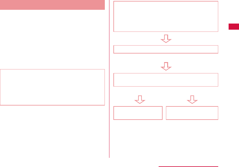
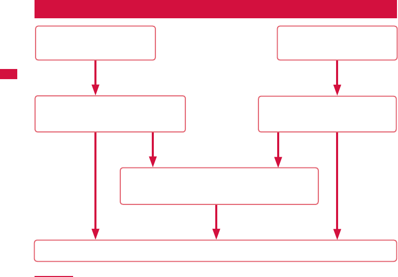
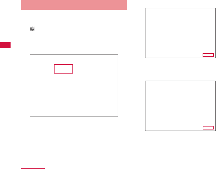
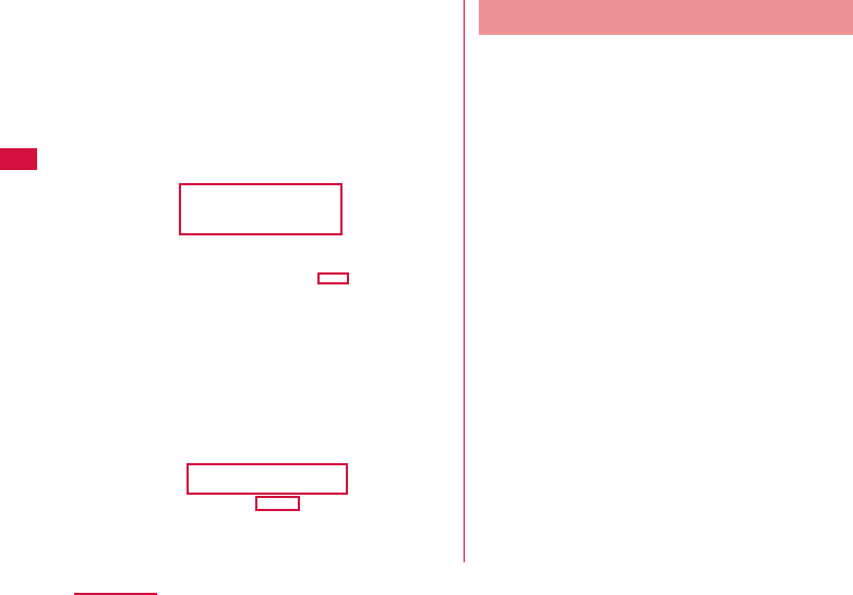
Display PIN1 code when powering on this
terminal or after login to setting page
(L-01G Connection Manager)
• When "PIN1 lock" on setting page is set to
"Locked" (P102), enter PIN1 code.
Enter PIN1 code
Fail three times in a row
Enter PIN Unlock code
Enter it from setting page (→P103)
OK Fail 10 times in a row
Set a new PIN1
code
Contact a docomo
Shop.

36
Before Using this Terminal
Caution
• Avoid setting PIN1 code to "your birthday",
"part of your phone number", "your address or
room number", "1111" or "1234", which can
be easily guessed by others. Take a memo of
PIN1 code to avoid forgetting.
• Do not reveal your PIN1 code to others.
DOCOMO is not responsible for damage
caused by misuse of your PIN1 code by
others.
• If you forget your PIN1 code, you need to
bring your identifi cation document (driver's
license, etc.), this terminal and docomo mini
UIM card to a docomo Shop.
For details, contact "General Inquiries"
provided on the back cover of this manual.
• Your PIN unblocking key is written in the
application form (copy for subscriber)
given at the time of contract. If you have
subscribed at a place other than a docomo
Shop, bring your identifi cation document
(driver's license, etc.), this terminal and
docomo mini UIM card to a docomo Shop, or
contact "General Inquiries" provided on the
back cover of this manual.
Attaching/Removing
Battery Pack
Please use the dedicated battery pack LXX for
this terminal.
Attaching
a Put your fi nger in the groove of
the back cover and hold it up in the
direction of the arrow to detach
37
Before Using this Terminal
b Align the battery pack with the metal
terminals of this terminal and attach
it in the direction of a with " " on
the battery pack facing up, and insert
in the direction of b
Align the tabs of this terminal with the dips on
the battery pack.
c Confi rm the orientation of the back
cover and align it with the main unit,
press the arrow parts one by one to
close the back cover fi rmly
Make sure that the groove and the arrow mark
are on the same side.
38
Before Using this Terminal
Removing
Note
• Make sure to turn off this terminal before
removing the battery pack. The operations
of this terminal may become improper if you
remove the battery pack with the power on.
a Put your fi nger in the groove of
the back cover and hold it up in the
direction of the arrow to detach
b Put your fi nger in the groove of this
terminal against the battery pack
and press in the direction of a. Lift
up in the direction of b and remove it
in the direction of c
c Confi rm the orientation of the back
cover and align it with the main unit,
press the arrow parts one by one to
close the back cover fi rmly
Make sure that the groove and the arrow mark
are on the same side.

39
Before Using this Terminal
Charging
■ Battery Charge
• Do not apply excessive force when inserting
or pulling out the connector. Insert or pull it
out slowly.
• When charging with an entirely empty battery
pack, it may take a while to power on this
terminal.
• The internal of this terminal may become
warm and the charging may stop when data
communicating during charging. In that
case, turn off this terminal and wait until this
terminal cools down. Then charge it again.
• Depending on the usage conditions, charging
may stop before the battery level reaches
100%. In that case, remove the battery
pack and attach it again. You can continue
charging.
• Do not remove the battery pack while
charging. If you remove the battery pack
during charging, this terminal may not power
on properly, or it may not be able to charge.
In that case, remove the battery pack, cables
from this terminal and connect them again.
■ Do not charge this terminal for a prolonged
time with its power turned on.
• If you charge this terminal for a prolonged time
with its power turned on, the battery pack will start
supplying power to this terminal after fi nishing
charging. This will reduce the actual usage time
and deplete the battery. If this happens, please
charge it again correctly. When charging again,
remove this terminal fi rst and connect it again.
■
Usage time of battery pack and estimated
charging time
For details about usage time and charging
time, refer to "Main Specifi cations" (P148).
■ Battery pack life
• Battery pack is a consumable supply. Every
time when you charge the battery, usable time
becomes short.
• When the usage time becomes about half
of a new battery, life of the battery pack is
assumed to be over. We recommend you to
replace the battery pack ahead of time. Also,
depending on the usage condition, the battery
pack may get swollen when the battery life is
running out. Note that it is not a problem.
• Data communicating while charging may
aff ect life of battery pack.

40
Before Using this Terminal
■ AC adapter
• For details, refer to the instruction manual of
AC adapter.
• AC adapter can be used from AC 100 V to
240 V.
• The shape of AC adapter plug is AC 100 V
(Japanese specifi cation). A conversion plug
adapter for the destination country is required
when using an AC adapter compatible from
AC 100 V to 240 V. Also do not use a
transformer for overseas travel to charge.

41
Before Using this Terminal
Charging with AC Adapter
It describes how to charge this terminal with
AC adapter 04 (optional).
a Insert it into the external connection
terminal of this terminal horizontally
with the side of B mark on microUSB
connector of AC adapter 04 facing up
b Insert the power plug of AC adapter
04 into power outlet
LED indicator lights up red and the charging
starts.
After charging is completed, LED indicator
turns to lighting green.

42
Before Using this Terminal
c When charging is completed, remove
the power plug of AC adapter 04
from the power outlet
d Remove the microUSB connector
of AC adapter 04 from this terminal
horizontally
■ DC adapter 03 (optional)
The DC adapter supplies power to charge
this terminal through a cigar lighter socket
(12 V/24 V) in a vehicle.
For details, refer to the instruction manual of
DC adapter 03.
Charging with PC
Connect this terminal to a PC with the supplied
USB cable L03 to charge this terminal on PC.
• About how to connect with a PC, refer to
"Attaching to/Removing from PC" (→P53).
• Depending on the condition of the PC, it may
take a while to fi nish charging, or it may not be
able to charge.
Power On/Of
Power On
a When the power is off , press the
power button for over two seconds
For fi rst time activating, "Startup Wizard" is
displayed.
43
Before Using this Terminal
b Following onscreen instructions to
operate
The following settings are required when
using this terminal following the onscreen
instructions.
• Language
• Provider
• SSID
• Public wireless LAN
• Shortcut
Note
• When it is powered on, network search
such as Xi area or FOMA area starts. When
connected to network, the network name is
displayed.
Also when it is powered on, connection with
compatible Wi-Fi devices is available.
• Lock screen is displayed when activating
this terminal after setting "Startup Wizard".
(→P46)
■ When PIN1 code has been set up
Enter PIN1 code.
a Enter PIN1 code and tap "OK"
• When back light turns off , press the power
button.
Note
• When PIN1 code is failed three times in a row, enter
PIN Unlock code in L-01G Connection Manager.
(→P103)
Power Off
a When the power is on, press the
power button for over two seconds
b "YES"
44
Before Using this Terminal
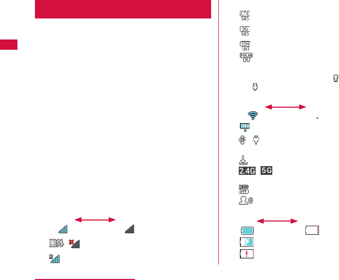
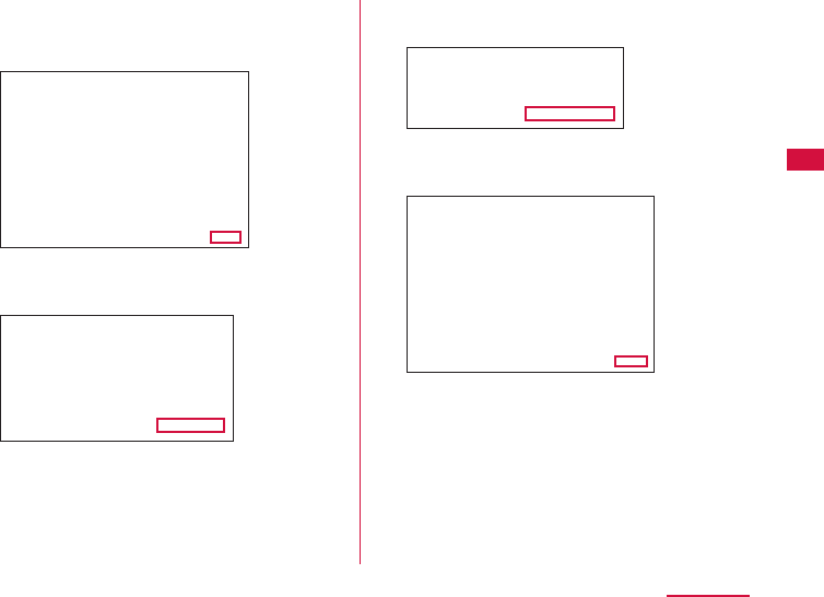
Viewing Display
The following shows the meaning of each icon
displayed on the screen (press the power
button when it is not displayed (→P46)).
Home screen
a Signal level
Strong Weak
/: Out of service/mobile networks
disconnected
: Roaming
b Connected network type
: LTE network connected
: 3G network connected (HSDPA/
HSUPA, W-CDMA)
: GSM network connected
: Connecting via public wireless LAN
• During communicating, " " (uploading) or
" " (downloading) is displayed in whitely.
c Wireless LAN receiving level
Strong Weak
: PWLAN on
d / : USB tethering/pocket charging mode
e : New software
f / : Wi-Fi frequency band 2.4 GHz/
Wi-Fi frequency band 5 GHz/
g : Wi-Fi auto off timer ON ( → P107)
h : Connected clients
i Remaining battery level
Full Empty
: Charging
Flashing
: Battery is almost empty. Please
charge.
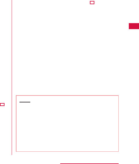
45
Before Using this Terminal
j PWLAN
Touch and hold this to switch public
wireless LAN on and off . When Wi-Fi is
turned off , it cannot be turned on.
k Wi-Fi Touch and hold this to switch
wireless LAN on and off .
l WPS Use WPS to set up Wi-Fi.
Touch and hold it to activate.
When Wi-Fi is turned off , it cannot be
turned on.
m Network
display
Displays the current connected
network name.
n Data communication amount display
(→P110)
o Menu Tap to display menu screen.
■ Example of state display
It displays information such as the charging
state of the battery pack, the state of Wi-Fi
function and network name (example screen is
shown below).
Charging (only
when the
power is off )
WPS function
being
activated
Battery is
empty
Wi-Fi function
Activating
Wi-Fi function
Disconnecting
No service
Charging
mobile device
Note
• Not like other smart phones, L-01G shows
the current time only when it can receive the
time information from the Internet. Therefore,
for the following cases it may not show the
current time correctly.
- Right after launching this terminal, from
out-of-service state to being connected to
network
- When accessing to the Internet overseas

46
Before Using this Terminal
Basic Operations
How to Use Touch Panel
This terminal adopts touch panel which allows
you to operate by touching the panel.
Precautions on touch panel usage
The touch panel is designed for fi nger touching
lightly. Do not press it hard with your fi nger or
with sharp objects (fi ngernail, ballpoint pen, pin
etc.).
The following actions may cause the touch
panel not working properly. Note that it may
cause wrong operations.
• Operating the screen with gloved hands
• Operating the screen with tip of a fi ngernail
• Operating the screen with an object on it
• Operating the screen with a protective sheet or
seal on it
Operations of touch panel
The following operations are available on the
touch panel.
• Tap: Touch the screen lightly
• Touch and hold: Touch the screen for over one
second
• Scroll: Move your fi nger upwards and downwards
while touching the screen.
Screen Unlock
Lock screen is displayed when pressing power
button after back light turned off , or when this
terminal is launched.
Press and hold to unlock.
About screen lock settings, refer to "Display
Settings" (→P110).
47
Before Using this Terminal
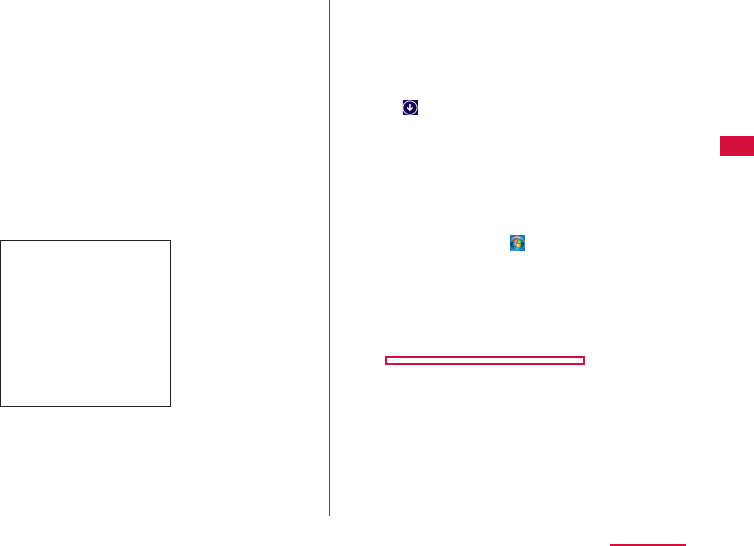
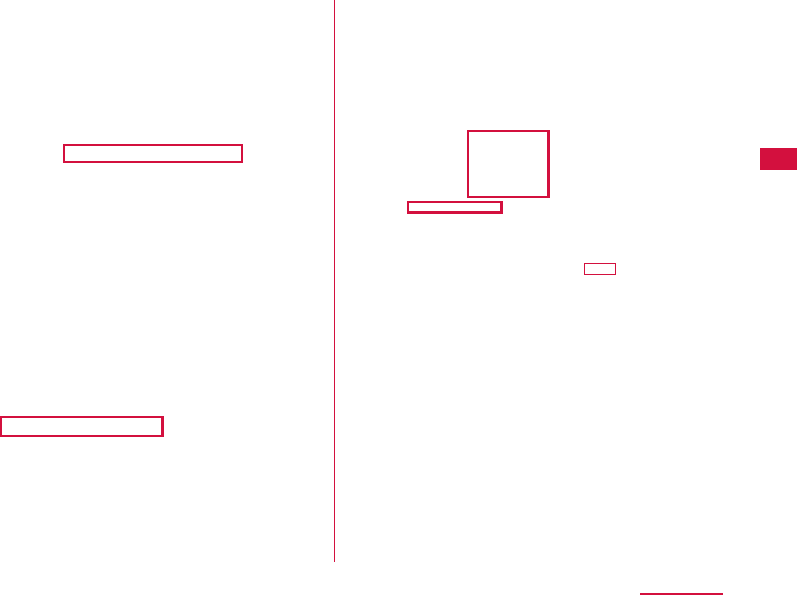
Menu Operations on this Terminal
Operate on the touch panel of this terminal
to set settings. For detailed settings, use
L-01G Connection Manager on PC to set up. For
details, refer to "Settings" (→P77).
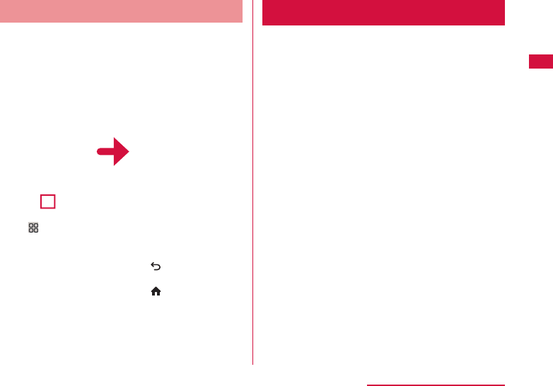
Tap " " Tap each menu to
display the setting
screen.
Tap " " to return to
upper tier.
Tap " " to return to
the Home screen.
Entering a Character
Operate on the touch panel of this terminal to
input characters, etc.
a Text box
b Cancel key
c Keyboard area
One key is assigned multi characters. Tap
the same key more than one time to input the
character you want.
d Shift key
Switch capital letters and small letters.
e OK key
f Delete key
Clear the character on the left side of the
cursor.
48
Before Using this Terminal
g Space key
Enter a space.
h Input switch key
Switch number/alphabet input.
i Input switch key
Switch number/symbol input.
a Tap keyboard area to input
characters.
The selected characters are input in the text
box.
• Select character type from alphabet/number/
symbol and tap the character to input.
• When entering letters which are assigned to
the same key consecutively, wait for one to
two seconds before entering the next letter.
Example: When entering "bc"
a
Tap "abc" key twice
b
After waiting for 1 to 2 seconds, tap
"abc" key three times.
b After fi nishing input, tap "OK"
Note
• In this terminal, only alphanumeric characters
and part of the symbols can be input
(~!@#$%^&*()-_+={}[]
|
\:;"'<>.?/,`).
49
Setting up
Setting up
Setup
Before using this terminal, set up the settings
required when connecting the Wi-Fi compatible
device you use to this terminal via Wi-Fi.
Also, you can change the wireless LAN or
settings of each function depending on your
usage environment.
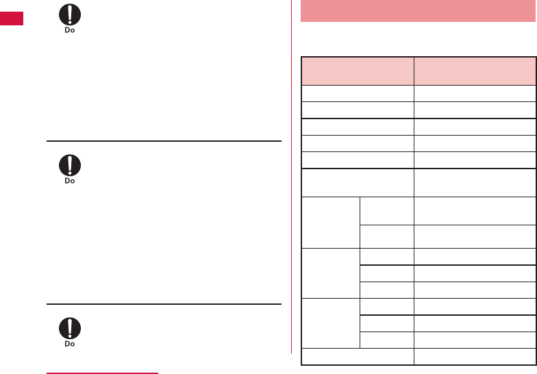
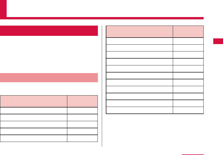
Confi rming the Compatible Device
This terminal supports the following OS/device.
(as of January, 2014)
OS/device
Setting change
of this terminal
Windows 8.1*1 32bit/64bit ○
Windows 8*1 32bit/64bit ○
Windows 7 SP1 32bit/64bit ○
Windows Vista SP2 32bit/64bit ○
Windows XP SP3 32bit ○
OS/device
Setting change
of this terminal
Mac OS X 10.9.1 64bit ○
Mac OS X 10.8.5 64bit ○
Mac OS X 10.7.5 32bit/64bit
○
Mac OS X 10.6.8 32bit/64bit
○
iPad*2 ○
iPod touch*2/iPhone*2 ○
Nintendo 3DS ╳
Nintendo DS ╳
PSP® "PlayStation® Portable" ╳
PS Vita ╳
Android terminal*2 ○
*1 Windows RT is not included.
*2 "SYSTEM" of L-01G Connection Manager →
"Backup & Restore" function cannot be used.
50
Setting up
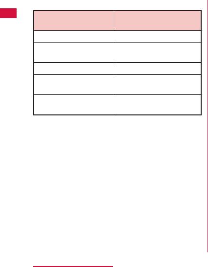
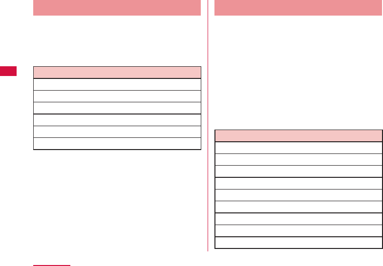
Using USB Cable
You can connect this terminal with a PC via
the supplied USB Cable L03 to use USB
tethering.
The supported OS information is shown below.
(as of January, 2014)
OS
Windows 8.1 32bit/64bit
Windows 8 32bit/64bit
Windows 7 SP1 32bit/64bit
Mac OS X 10.9.1 64bit
Mac OS X 10.8.5 64bit
Mac OS X 10.7.5 32bit/64bit
Data communication is possible when charging
with USB Cable.
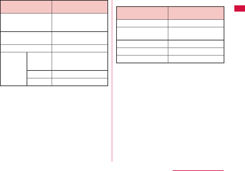
Using Wi-Fi Compatible Device
• For Wi-Fi compatible devices which support
IEEE802.11 a/b/g/n (2.4 GHz/5 GHz)/ac, you
can connect it with this terminal and start use.
• We do not guarantee any operations used on
your PC even when the operating condition
is matching. Operations may not be proper
depending on the usage environment you use,
such as the peripheral devices, application, etc.
• For operations or operating method of Wi-Fi
compatible device, contact source manufacturer.
• The supported OS/device information is shown
below. (as of January, 2014)
OS/device
Windows 8.1 32bit/64bit
Windows 8 32bit/64bit
Windows 7 SP1 32bit/64bit
Windows Vista SP2 32bit/64bit
Windows XP SP3 32bit
Mac OS X 10.9.1 64bit
Mac OS X 10.8.5 64bit
Mac OS X 10.7.5 32bit/64bit
Mac OS X 10.6.8 32bit/64bit
51
Setting up
OS/device
iPad
iPod touch/iPhone
Nintendo 3DS
Nintendo DS
PSP® "PlayStation® Portable"
PS Vita
Android terminal
For operating environment of the latest
information, confi rm DOCOMO website.
Note
• You may not be able to use depending on
your environment and device. Note that
we are not responsible for any inquiries
and operations used in other operating
environments.
52
Setting up
Setup Flow
Connecting via Wi-Fi
(→P62)
Connecting via USB Cable
(→P53)
・Setting on PC ( → P62)
・Setting on Mac ( → P66)
・Setting on portable device (→P68)
Setting in L-01G Connection Manager
・For public wireless LAN setting ( → P84)
・For provider setting ( → P82)
Connecting to the Internet
Installing driver
・For Windows ( → P54)
・For Mac ( → P58)

53
Setting up
Note
• To change the settings of this terminal,
connect to a PC and change the settings
fi rst before connecting to other Wi-Fi
compatible devices.
* Also, for terminals support browser,
settings of the terminal main unit can be
changed not only with PC. However, part
of the menu cannot be used. Depending
on the browser, it may not be able to use.
For Wire Connection
Attaching to/Removing from PC
Use the supplied USB Cable L03 to attach to
a PC.
• When USB tethering is turned on, it is connected
to the Internet automatically when connecting
to a PC. Note that the packet communication
(charging target) is charged.
• Note that if you remove the USB cable from a PC
during data communication, data communication
is disconnected and false operations or loss of
data may result.
54
Setting up
Attaching
a Power on the PC
b Insert the microUSB connector of
the USB cable L03 into the external
connection terminal of this terminal
horizontally with the USB mark facing
up
c Insert the USB connector of USB
cable L03 to the USB port of PC
• When connecting for the fi rst time after
purchase, setup screen of L-01G driver is
displayed automatically via zero installation
only for Windows version. Follow the on-
screen instructions to install (→P54)
• LED indicator lights up red and the charging
starts.
Removing
a Remove the USB cable L03 from
both PC and this terminal
Installing Driver (Windows PC)
When connecting for the fi rst time after
purchase, setup screen of L-01G driver is
displayed automatically via zero installation
only for Windows version. Follow the on-screen
instructions to install
• After installation, on the desktop screen, shortcut
of L-01G Connection Manager is generated.
Note
• Do not cancel or remove this terminal during
installation of the driver.
55
Setting up
Screen displays are taken from Windows 8.1
as example.
a Click "CD Drive (X:) DOCOMO" (X
part diff ers depending on the PC) on
the top right
b Click "Run docomo_L01G_
ModemDriver_Ver_X.X.X_WHQL_All.
exe"
• When user account control screen is
displayed, click "Yes".
• For Windows 7, operate from step 2.
• When installer is not activated
automatically, or if the installer is not
activated automatically even after this
terminal is connected, follow the steps
below.
• For Windows 8.1, on the desktop screen,
"PC" "CD Drive (X:) DOCOMO" (X
part diff ers depending on the PC).
• For Windows 8, on the desktop screen,
swipe from the right side of the screen
(point the top right of the screen in
case of mouse) from charm, "Search"
"Apps" "Computer" "CD Drive "X:"
DOCOMO" (X part diff ers depending on
the PC).
• For Windows 7, (Start) "Computer" .
c Select "English (United States)" and
click "Next"

56
Setting up
d Select "I accept the terms of the
license agreement" and click "Next"
e When "Welcome to the InstallShield
Wizard for docomo L01G" is
displayed, click "Next"
Installation starts.
f Select "Optimize communication
settings (W-TCP Setting)
(Recommended)" and click "Next"
g Select "Yes, I want to restart my
computer now." and click "Finish"
PC is restarted automatically.
57
Setting up
Confi rming the Installed L-01G
Driver
Confi rm if L-01G driver is set in PC. Connect
L-01G with a PC via the supplied USB Cable
beforehand.
Screen displays are taken from Windows 8.1
as example.
a On the desktop, "Control Panel"
"Hardware and Sound"
• For Windows 8, on the desktop screen,
swipe from the right side of the screen (point
the top right of the screen in case of mouse)
from charm, click "Search" "Apps"
"Control Panel" "System and Security".
• For Windows 7, (Start) "Control Panel"
"System and Security".
b Click "Device Manager"
c Click each device display and confi rm
the installed driver name
• Network adapters: docomo L01G USB NDIS
Driver
• Ports (COM & LPT): docomo L01G USB
Serial Port (COMX)
• Modems: docomo L01G Modem Driver
• Universal Serial Bus controllers: USB
Composite Device
Note
• After inserting this terminal to the USB
port of PC, if this terminal is not recognized,
insert with another USB port and confi rm it.
Depending on the PC, this terminal may not
be recognized with certain USB ports.
58
Setting up
Installing Driver (Mac)
Screen displays are taken from Mac OS X
10.9.1 as example.
a (Finder) → "DEVICES"
→ "DOCOMO" →
"NTTDOCOMOINCL01GDRIVERS.
pkg"
• When screen related to "reliability of
software source" is displayed, click
"Continue".
b Click "Continue"
• When you agree on "Software License
Agreement", click "Agree".
c Click "Continue"
• When "Change Install Location" screen is
displayed, select an installation destination
and click "Continue".
59
Setting up
d "Standard Install on "Macintosh HD""
screen is displayed, and click "Install"
Authentication screen is displayed.
e Enter the Mac name (user name) and
password, and click "Install Software"
f Click "Continue Installation"
Installation starts.
g Click "Restart" on the installation
complete screen

60
Setting up
For Wireless Connection
Setting procedures are diff erent depending on
the Wi-Fi compatible device you use. Here it
describes setting procedures of each terminal
below.
• Windows PC (for Windows 8.1) ( →P62)
• Windows PC (for Windows 7 or Windows Vista)
(→P64)
• Windows PC (for Windows XP) ( → P65)
• Mac ( → P66)
• iPad ( → P68)
• Android ( → P69)
• Nintendo DS ( → P69)
• PSP ( → P70)
• Wi-Fi compatible device which supports WPS
(→P71)

61
Setting up
Note
• For those settings, set them up when
connecting each terminal for the fi rst time.
Once it is set up, auto connection starts
after turning on this terminal.
• When connecting without using WPS
function, enter the SSID and security key
set up in this terminal. (→P61) Confi rm
beforehand and set the settings.
• Up to 10 Wi-Fi compatible devices can be
connected to this terminal at the same time.
• For Windows and Mac, log in by a user
account with administrator authority.
■ SSID/security sticker
Confi rm the SSID and security key from
the bundled "SSID/security sticker". Also
SSID and security key are written on the
sticker inside of the main unit after removing
the battery pack (→P36 "Attaching/
Removing Battery Pack").
You can also confi rm from the setting menu of
this terminal. (→P115)

62
Setting up
■ SSID/security sticker
You can use two SSID on this terminal. For
default SSID, refer to the bundled "SSID/
security sticker" and the sticker inside the
main unit for their meaning.
Primary SSID:
Use the "SSID:" written on the sticker It
can be used in wireless LAN security mode
which is over WPA and the security key uses
"SECURITY KEY:".
Secondary SSID:
Replace the "_A" at the end of the "SSID:"
written on the sticker with "_B". About the
settings of secondary SSID, refer to "Setting
Secondary SSID" (→P92).
Connecting to Windows PC
The setting procedures described here is
an example when the security mode of this
terminal is set to the default setting of "WPA/
WPA2-PSK mixed".
• Encryption scheme used of default setting is
TKIP/AES when connecting via WPA-PSK, and
TKIP/AES when connecting via WPA2-PSK.
For Windows 8.1
a Press the power button of this
terminal for over two seconds
This terminal is turned on. When Wi-Fi is OFF,
turn it on.
b Turning on Wi-Fi function on PC
c On the desktop screen, "Control
Panel" "Network and Internet"
"Network and Sharing Center"
• For Windows 8, on the desktop screen,
swipe from the right side of the screen (point
the top right of the screen in case of mouse)
from charm, "Search" "Apps" "Control
Panel" "Network & Internet" "Network
and Sharing Center".
63
Setting up
"Network and Sharing Center" window is displayed.
d Click "Set up a new connection or
network"
e Click "Manually connect to a wireless
network" "Next"
f Enter the SSID (default setting:
"L01G_XXXXXXXX_A" →P61) set
in this terminal in "Network name"
g Select "WPA2-Personal" in "Security
type"
• For Windows 8, you can select "WPA-
Personal", however, security of "WPA2-
Personal" is higher.
• For Windows 8, select "TKIP" or "AES" in
"Encryption type". Security of "AES" becomes
high.
h Enter the security key set in this
terminal in "Security Key" (→ P61)
64
Setting up
i Mark "Start this connection
automatically" and click "Next"
j
When "Successfully added L01G_
XXXXXXXX_A" is displayed, click
"Close"
For Windows 7 and Windows Vista
a Press the power button of this
terminal for over two seconds
This terminal is turned on. When Wi-Fi is OFF,
turn it on.
b Turning on Wi-Fi function on PC
c Click (Start) "Control Panel"
"Network and Internet" "Network
and Sharing Center"
"Network and Sharing Center" window is
displayed.
d Click "Connect to a network"
e Click the displayed SSID set in this
terminal (default setting: "L01G_
XXXXXXXX_A"→ P61) and click
"Connect"

65
Setting up
f Enter the security key (→ P61)
set in this terminal in "Security key"
and click "OK"
For Windows Vista, enter the security key set
in this terminal in "Security key or passphrase"
and click "Connect".
g Mark "Save this network" and "Start
this connection automatically" and
click "Close"
The procedure is not necessary for Windows 7.
For Windows XP
a Press the power button of this
terminal for over two seconds
This terminal is turned on. When Wi-Fi is OFF,
turn it on.
b Turning on Wi-Fi function on PC
c Click Start "Control Panel"
"Network and Internet Connections"
"Network Connections"
d Double click "Wireless Network
Connection"
"Wireless Network Connection" window is
displayed.
66
Setting up
e Click the displayed SSID set in this
terminal (default setting: "L01G_
XXXXXXXX_A"→ P61) and click
"Connect"
f Enter the security key (→ P61)
set in this terminal in "Network key"
and "Confi rm network key" and click
"Connect"
Connecting to Mac
The setting procedures in Mac OS X 10.9.1
described here is an example when the security
mode of this terminal is set to the default
setting of "WPA/WPA2-PSK mixed" (Encryption
scheme supports AES and TKIP).
a Press the power button of this
terminal for over two seconds
This terminal is turned on. When Wi-Fi is OFF,
turn it on.
b "System Preferences..." on apple
menu "Network"
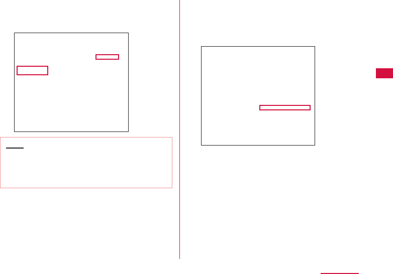
67
Setting up
c Select "Wi-Fi" and click "Turn Wi-Fi
On"
Wi-Fi function on Mac is turned on.
Note
• When "All preferred networks can not be
used" is displayed, click "Cancel" and then
"Ask to join new networks" to cancel the
selection.
d Click "Network Name" and select the
displayed SSID set in this terminal
(default setting: "L01G_XXXXXXXX_
A" →P61)
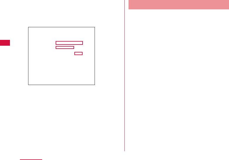
68
Setting up
e Enter the security key ( → P61)
set in this terminal in "Password",
select "Remember this network" and
click "Join"
Connecting to iPad
The setting procedures in iPad described
here is an example when the security mode of
this terminal is set to the default setting of
"WPA/WPA2-PSK mixed" (Encryption scheme
supports AES and TKIP).
a Press the power button of this
terminal for over two seconds
This terminal is turned on. When Wi-Fi is OFF,
turn it on.
b From iPad home screen, tap "Settings"
c Tap "Wi-Fi" and turn on Wi-Fi
d Tap the displayed SSID set in this
terminal (default setting: "L01G_
XXXXXXXX_A"→ P61)
e Enter the security key ( → P61)
set in this terminal, tap "Join"

69
Setting up
Connecting Android
The setting procedures in Android described
here is an example when the security mode of
this terminal is set to the default setting of
"WPA/WPA2-PSK mixed" (Encryption scheme
supports AES and TKIP).
a Press the power button of this
terminal for over two seconds
This terminal is turned on. When Wi-Fi is OFF,
turn it on.
b From the Home screen of Android,
"Menu" → "Settings"
c "Wi-Fi" → "Wi-Fi switch" to turn on
Wi-Fi
d Tap the displayed SSID set in this
terminal (default setting: "L01G_
XXXXXXXX_A" →P61).
e Enter the security key ( → P61) set
in this terminal, tap "Connect"
Connecting to Nintendo DS
The setting procedures in Nintendo DSi
described here is an example when the security
mode of this terminal is set to the default
setting of "WPA/WPA2-PSK mixed" (Encryption
scheme supports AES and TKIP).
a Press the power button of this
terminal for over two seconds
This terminal is turned on. When Wi-Fi is OFF,
turn it on.
b From DSi menu of Nintendo DSi, " 本体
設定 (Unite settings)"
c "インターネット (Internet)" "接続設定
(Connection settings)"
d "上級者設定 (Advantage settings)"
touch an access point from those
displayed as "未設定 (No setting)"
e "アクセスポイントを検索 (Search an
access point)"
f Touch the displayed SSID set in this
terminal (default setting: "L01G_
XXXXXXXX_A"→ P61)

70
Setting up
g Enter the security key (→P61) set
in this terminal, tap "OK"
h "OK"
Settings are saved.
i "OK"
Connection test starts.
Connecting to PSP
The setting procedures in PSP-3000 described
here is an example when the security mode of
this terminal is set to the default setting of
"WPA/WPA2-PSK mixed" (Encryption scheme
supports AES and TKIP).
a Press the power button of this
terminal for over two seconds
Power on this terminal and turn on Wi-Fi
function if it is OFF.
b Switch on PSP wireless LAN
c From the Home screen, "Settings"
"Network settings" and press "○ "
button
d Select "Infrastructure Mode" and
press "○ " button
e Select "New Connection" and press
"○ " button
f Select "Scan" and press the direction
key "△ " button
g Select the displayed SSID set in this
terminal (default setting: "L01G_
XXXXXXXX_A"→ P61) and press
"○ " button
h Confi rm the SSID displayed and
press the direction key of "
△
" button
i Select "WPA-PSK (TKIP)" or "WPA-
PSK (AES)" and press the direction
key of "
△
" button
• Security of "WPA-PSK (AES)" becomes high.
j
Press "○ " button
k Enter the security key ( → P61)
set in this terminal and press the
direction key of "
△
" button
l
Select "Easy" and press the direction
key of "
△
" button

71
Setting up
m Confi rm the connection name displayed
and press the direction key of "
△
"
button
n
Confi rm the setting list displayed and
press the direction key of "
△
" button
o
Press "○ " button
Settings are saved.
p
Press "○ " button
Connection test starts.
Connecting to Wi-Fi Compatible
Device Supports WPS
Note
• Setting method is diff erent depending on
the Wi-Fi compatible device. Refer to the
instruction manual of the Wi-Fi compatible
device you use to ensure your operations.
• When the PIN code of WPS function on the
Wi-Fi compatible device you use is specifi ed,
select "PIN(From Client)" from "WPS type" on
this terminal and set the PIN code specifi ed
in "PIN" beforehand. (→P93)
• In "Security" ( → P90), when it is set to the
following settings, WPS function cannot be
used.
- WEP
- WPA-PSK
- WPA2-PSK (TKIP)
- WPA/WPA2-PSK mixed (TKIP)
• When "SSID Stealth" is set to "On", WPS
function cannot be used.

72
Setting up
■ Example when "WPS type" is set to "button"
a Press the power button of this
terminal for over two seconds
This terminal is turned on. When Wi-Fi is OFF,
turn it on.
b Turn on Wi-Fi function on the Wi-Fi
compatible device being connected
and set up WPS function if necessary
Operations are diff erent depending on the Wi-
Fi compatible device you use.
c Operate connection via WPS function
on the Wi-Fi compatible device being
connected
Operations are diff erent depending on the Wi-
Fi compatible device you use.
d Touch and hold WPS of this terminal
and release
e Follow the screen display on the Wi-
Fi compatible device being connected
to set up
Operations are diff erent depending on the Wi-
Fi compatible device you use.
■ Example when "WPS type" is set to
"PIN(From AP)"
a Press the power button of this
terminal for over two seconds
This terminal is turned on. When Wi-Fi is OFF,
turn it on.

73
Setting up
b Activate Web browser on the PC
connected via Wi-Fi function, log in
to the setting page of this terminal
(L-01G Connection Manager)
c Select "PIN(From AP)" in WPS form
fi eld of WPS setting page on the setting
page (L-01G Connection Manager) you
logged in
d Click "Create" in the PIN fi eld on the
WPS setting page and create WPS
PIN
A 8-digit WPS PIN code is displayed.
e Turn on Wi-Fi function on the Wi-Fi
compatible device being connected
and enter the 8-digit WPS PIN code
in "WPS-PIN"
When check mark is displayed on this terminal,
access to WPS is successful.
■ Example when "WPS type" is set to
"PIN(From client)"
a Press the power button of this
terminal for over two seconds
This terminal is turned on. When Wi-Fi is OFF,
turn it on.
b Activate Web browser on the PC
connected via Wi-Fi function, log in
to the setting page of this terminal
(L-01G Connection Manager)
c Select "PIN(From client)" in WPS form
fi eld of WPS setting page on the setting
page (L-01G Connection Manager) you
logged in
d Turn on Wi-Fi function on the Wi-Fi
compatible device being connected
and select "WPS-PIN" access
A 8-digit WPS PIN code is displayed on the Wi-
Fi compatible device side.

74
Setting up
e Enter the 8-digit number displayed
on the Wi-Fi compatible device
side in the PIN fi eld of WPS
setting page on the setting page
(L-01G Connection Manager) you
logged in, click "Start"
When check mark is displayed on this terminal,
access to WPS is successful.
Setting Each Item
Activate Web browser on the PC connected
by Wi-Fi and display the setting page of this
terminal. Change the settings according to
the usage environment of settings on this
terminal.
• It can also be set via USB tethering on a PC.
In that case, set "USB tethering" to "ON" in the
setting menu of this terminal. (→P114)
* Also, for terminals support browser, settings of
the terminal main unit can be changed not only
with PC. However, part of the menu cannot be
used. Depending on the browser, it may not be
able to use.
* Same settings are in setting menu of this
terminal.
For details, refer to "Settings (Web browser)"
(→P77) or "Settings (setting menu on this
terminal)" (→P108).

75
Connecting to the Internet
Connecting to the Internet
Internet Connection
To connect to the Internet via this terminal,
subscription of an Internet service provider
(mopera U, etc.) compatible with service and
data communication is required.
For details, visit DOCOMO website.
Connection settings with the Internet service
provider is registered in the profi le of this
terminal.
For details about the setting method, refer to
"Adding Access Point" (→P82).
• Up to 10 profi les can be registered.
• The setting is not necessary when it is used
after connecting to mopera U
Connecting to the Internet
After powering on this terminal, it connects
to the access point set up in the profi le
automatically to enable the usage of the
Internet. Confi rm the connection of the
Internet through the Wi-Fi compatible device
you use.
About how to choose an access point when
more than one profi le have been registered,
refer to "Setting Network Search" (→P120).

76
Connecting to the Internet
Connecting to the Internet
Using Public Wireless LAN
Connect to public wireless LAN such as a
station or a cafe to use the Internet. Set up
"PWLAN" (→P84).
• When using the public wireless LAN service, a
separate subscription or settings are required.
Contact the service provider you use for detailed
setting information etc.
77
Settings (Web browser)
Settings (Web browser)
Logging in to the Setting Page
(L-01G Connection Manager)
Activate Web browser on the PC connected
by Wi-Fi and display the setting page
(L-01G Connection Manager) of this terminal.
You can set up each function.
• Only the Wi-Fi compatible devices connected
to primary SSID can log in to the setting page.
The Wi-Fi compatible devices connected to
secondary SSID cannot log in.
• For PC, it can also be set via USB tethering.
In that case, set "USB tethering" to "On" in the
setting menu of this terminal. (→P114)
• Depending on the items, the same settings can
be made in the setting menu of this terminal.
Note
• For terminals support browser, settings of
the terminal main unit can be changed not
only with PC. However, part of the menu
cannot be used. Depending on the browser,
it may not be able to use.
• The setting page on this terminal supports
the following Web browsers.
Windows: Microsoft Internet Explorer
10 or later, Firefox 22 or later,
Google Chrome 28 or later,
Opera 15 or later
Mac OS X: Safari 6.0 or later
Android: Basic browser
iOS: Basic browser
* Depending on the browser you use,
screens or items may not ba able to
display.
* In browser settings, set Cookie to valid
(Save, accept).
* In browser settings, set Cache to invalid
(Not save, always confi rm).

78
Settings (Web browser)
a Press the power button of this
terminal for over two seconds
This terminal is turned on and Wi-Fi function is
turned on.
b Activate PC and turn on Wi-Fi
function
This terminal is connected with the PC via Wi-Fi.
• For the fi rst time connection, setup of Wi-Fi
connection is necessary. Refer to "For Wireless
Connection" (→P60) and set it up.
c Activate Web browser, enter
"http://192.168.225.1/" in address
input fi eld and press Enter key
"Login" screen is displayed.
• When L-01G driver is installed on the
Windows PC, double click the shortcut of
L-01G Connection Manager on the desktop
screen and display "Login" screen.
• "192.168.225.1" is the default setting of
the private UP address of this terminal.
When changing the setting, enter the private
IP address you set up (→P95 "Setting
DHCP function").
d Enter the login password (default:
"1234") in "Password" fi eld and click
"Login"
• "Admin" is displayed in "Username" fi eld. You
cannot change the setting.
• In "Language" fi eld, select a language
displayed in setting page.
79
Settings (Web browser)
■ When setting PIN1 code
PIN1 code confi rmation screen is displayed.
Click "Refresh", unlock PIN1 code on this
terminal and log in again.
Note
• To ensure the security, we recommend
change the default login password. For
detailed information, refer to "Changing Login
password" (→P104).
Screen of Setting Page
a
Top menu
Click a menu item and switch to the setting
page.
You can select the following items.
• STATUS ( → P80)
• PROVIDER ( → P82)
• PWLAN ( → P84)
• MOBILE NETWORK ( → P86)
• Wi-Fi ( → P87)
• ROUTER ( → P97)
• SYSTEM ( → P102)
Depending on the item you selected, sub menu
is displayed and the setting screen is changed.
80
Settings (Web browser)
b
"Logout"
Click it when logging out from the setting page.
c
Setting screen
Setting items of the function you selected in
menu item are displayed.
d
Click it when changing the settings.
e
Click it when updating the display content in
"Status" screen.
f
Help is displayed.
Confi rming Connection State or
Setting State of this Terminal
a Click "STATUS" of the top menu
"Status" screen is displayed.
• Click to update the information.
Network selection
(LTE/3G/GSM)*
:
The network type (LTE/3G/
GSM) being connected is
displayed.
Network name*:The network name being
connected is displayed.
FOMA/Xi signal
strength*
:The current reception level is
displayed.
Wi-Fi status :
Wi-Fi function status is
displayed.

81
Settings (Web browser)
Frequency band
(Wi-Fi)
:
The frequency band used to
access to wireless LAN is
displayed.
Public WLAN :
The setting status of the
connection function accessing
to the public wireless LAN is
displayed. When connecting
via public wireless LAN, the
name of the access point being
connected is displayed.
Connected
clients
:The number of the terminals
connected via Wi-Fi currently is
displayed.
Wi-Fi auto off
timer
:The setting status of the Wi-Fi
auto off timer is displayed.
WPS :
The setting status of WPS is
displayed.
Phone number*:The phone number of docomo
mini UIM card is displayed.
Network data
usage*
:The setting status of whether
to show data communication on
this terminal is displayed.
Interface
information
:IP address, MAC address, etc.
are displayed.
* When docomo mini UIM card is not inserted, this
item is not displayed. Also, "−" is displayed in
"Phone number" fi eld, and "DOCOMO UIM card
has not been inserted properly or is invalid." is
displayed in "Status" screen.

82
Settings (Web browser)
Setting Provider
Adding Access Point
Register, edit and delete an access point. Up
to 10 access points can be registered.
• The settings for connecting to mopera U preset
at the time of purchase cannot be deleted. When
using mopera U. the following settings are not
necessary.
a Click "PROVIDER" on the top menu
b When registering a new access point,
click "Add New"
c Set up each item in setting screen
Profi le name
Enter a name of the access point within the
following range.
• Up to 15 characters of single byte
alphanumeric characters and single byte
space
Access point name
Enter a name of APN within the following
range.
• Up to 99 characters of single byte
alphanumeric characters and symbol
(~!@#$%^&*-_:,./;|()<>{}[]+=`"'?\) and single
byte space
Username
Enter a user name specifi ed by provider
within the following range.
• Up to 64 characters of single byte
alphanumeric characters and symbol
(~!@#$%^&*-_:,./;|()<>{}[]+=`"'?\) and single
byte space
Password
Enter a password specifi ed by provider within
the following range.
• Up to 32 characters of single byte
alphanumeric characters and symbol
(~!@#$%^&*-_:,./;|()<>{}[]+=`"'?\) and single
byte space

83
Settings (Web browser)
Authentication
Select a Authentication for the access point.
• None
• PAP
• CHAP
d When registering a new access point,
click "Save"
e Click "Apply" to save the settings
Note
• The registered profi le name cannot be
changed.
When changing profi le name, delete the
profi le and register again.
■ When setting a registered access point to
profi le
a
Select an access point set to profi le in "Profi le
selection"
b
Click "Apply"
■ Edit an existing access point and set up the
profi le
a
Select an access point in "Profi le selection" to
edit
b
Edit the item you want to change the setting
c
Click "Apply"
■ Delete an access point
a
Select an access point in "Profi le selection" to
delete
b
Click "Delete"
c
Click "OK"

84
Settings (Web browser)
Setting Public Wireless
LAN
You can connect to wireless LAN router at
home or at work, or connect to the public
wireless LAN service outside to access to the
Internet.
• When using the public wireless LAN service, a
separate subscription or settings are required.
Contact the service provider you use for detailed
setting information etc.
a Click "PWLAN" of the top menu
b Set up each item in setting screen
Public WLAN
Set whether to use the connection function
to access to the public wireless LAN.
• On
• Off
■ When using
Display mode
Switch SSID display settings.
• Used networks: Displays all the access
points.
• Registered networks: Search and
display the registered access point as
the AP specifi ed by user.
Network notifi cation
When an non-encrypted access point
which is not in connection history is
detected, it notifi es.

85
Settings (Web browser)
Searching result
Click "Scan" to display the available
access points in list.
• : Connect to an access point.
• : Disconnect the access point being
connected.
• : Up to 10 access points can be
registered as the AP specifi ed by user.
Connection history
Up to 10 connection histories to the
access point are displayed.
• : Delete an access point.
• : Change the settings of an access
point.
• / : Change the priority order when
connecting to an access point.
Add network
Add an access point. Set "AP name" and
"Security", click "Save".
■ When setting to WEP
Password
Enter security key for WEP.
5, 10, 13 and 26 single byte alphameric
characters can be input as a key.
• For 5 characters or 13 characters,
single byte alphanumeric characters (0
to 9, a to z, A to Z)
• For 10 characters or 26 characters,
hex number (0 to 9, a to f, A to F)
■ When setting WPA/WPA2-PSK
Password
Enter a 8 to 64 characters for security
key of WPA/WPA2.
• For key of 8 to 63 characters, single
byte alphanumeric characters (0 to 9,
a to z, A to Z) and symbol (~!@#$%^&*-
_:,./;|()<>{}[]+=`"'?\)
• For key of 64 characters, hex number (0
to 9, a to f, A to F)
■ When setting EAP-SIM
Auto authentication, no specifi c settings.
■ When setting EAP-AKA
Auto authentication, no specifi c settings.
c When selecting an access point from
"Searching result", enter the security
key
d Click "Apply" to save the settings
86
Settings (Web browser)
Setting Network
Selecting an Access Point
You can specify the network of the access
point. (→P120)
• This function cannot be used inside Japan.
Displaying Data Communication
Amount
Data amount used for communication is
displayed. Data communication amount
overseas is not counted. Also data
communication during international roaming is
not displayed.
a Click "MOBILE NETWORK" on the top
menu
b Click "Network data usage" of the
sub menu
c Set up each item in setting screen
Current data usage
Click "Refresh" to check the latest
information.
Click "Reset" to clear the usage amount
information.
For the following case, the usage amount is
reset automatically.
• First of each month 0 o'clock
• When replacing docomo mini UIM card
• When unlocking SIM
Display mode
• Used data only: Data communication
amount is displayed on this terminal.
• Used data with max data: The current
usage amount and the upper limit of data
communication amount are displayed on
this terminal.
• Off : Data communication amount is not
displayed on this terminal.

87
Settings (Web browser)
Maximum data size
Select "Used data with max data" in "Display
mode" to input.
Enter valid value*.
* Valid value: positive integer of 1 to 99
Invalid value: numbers other than minus, 0,
decimal point and valid value
* Even if the top data communication
amount is set, the communication is not
stop when it reaches the top limit amount.
Use as an estimate standard.
d Click "Apply" to save the settings
Advanced Settings of
Wireless LAN
Note
• When using Wi-Fi function overseas, confi rm
conditions such as available frequency or
regulations of the country to use it.
Setting Basic Functions of Wi-Fi
a Click "Wi-Fi" of the top menu
b
Click "Basic setting" of the sub menu
c Set up each item in setting screen

88
Settings (Web browser)
Frequency band
Set the frequency band you use.
• 2.4GHz
SSID/Key Display on modem
Set whether to display the security key in
"Basic setting" of the setting menu on this
terminal.
• On
• Off
Privacy separator
Set if communication between clients
connected to diff erent SSID is available.
When Privacy separator is set to valid,
communication between wire connected
network device and Wi-Fi compatible devices
connected to diff erent SSID is not available.
• On
• Off
* Communication between Wi-Fi compatible
devices connected to the same SSID is
not aff ected.
■ 2.4GHz setting
Channel
Select a channel of wireless LAN.
* When connected to public wireless
LAN, it changes to the channel of the
connected access point automatically.

89
Settings (Web browser)
IEEE802.11 Mode
Select an operation mode of wireless LAN.
• 11b only
• 11b/g
• 11g only
• 11n only
• 11b/g/n
(When wireless LAN security (→P90)
is set to "WEP", or when setting to "WPA-
PSK", "WPA2-PSK", "WPA/WPA2-PSK
mixed" and selecting "TKIP", "11n only"
and "11b/g/n" cannot be selected. )
WLAN Bandwidth
Select wireless LAN bandwidth.
• 20MHz
• 20/40MHz: Available to select only
when "IEEE802.11 Mode" is set to
"11b/g/n" or "11n only".
MIMO
Select whether to use MIMO function.
• On
• Off
■ 5GHz setting
Channel
Select a channel of wireless LAN.
* When connected to public wireless
LAN, it changes to the channel of the
connected access point automatically.
IEEE802.11 Mode
Select an operation mode of wireless LAN.
• 11a only
• 11n only
• 11ac only
• 11a/n
• 11/a/n/ac
(When wireless LAN security (→P90)
is set to "WEP", or when setting to "WPA-
PSK", "WPA2-PSK", "WPA/WPA2-PSK
mixed" and selecting "TKIP", "11a only"
can be selected. )
WLAN Bandwidth
Select wireless LAN bandwidth.
• 20MHz
• 20/40MHz: Available to select only
when "IEEE802.11 Mode" is not set to
"11a only".
• 80MHz: Available to select only when
"IEEE802.11 Mode" is set to "11ac
only".
• 20/40/80MHz: Available to select
only when "IEEE802.11 Mode" is set to
"11a/n/ac".
MIMO
Select whether to use MIMO function.
• On
• Off
d Click "Apply" to save the settings

90
Settings (Web browser)
Setting Security Mode of
Wireless LAN
a Click "Wi-Fi" of the top menu
b Click "SSID setting " of the sub menu
c Set each item of primary SSID in
setting screen
SSID
Enter SSID name within the following range.
• Up to 32 characters, single byte
alphanumeric characters (0 to 9, a to z, A
to Z) and symbol (~!@#$%^&*-_:,./;|()<>{}
[]+=`"'?\)
Security
Setting security mode of wireless LAN.
• Open
• WEP
• WPA-PSK
• WPA2-PSK
• WPA/WPA2-PSK mixed
The setting items are diff erent depending on
the settings of security mode.
■ When setting to Open
No special settings.
■ When setting to WEP
PASSWORDS
Enter security key for WEP.
5, 10, 13 and 26 single byte alphameric
characters can be input as a key.
• For 5 characters or 13 characters,
single byte alphanumeric characters (0
to 9, a to z, A to Z)
• For 10 characters or 26 characters,
hex number (0 to 9, a to f, A to F)
■ When setting to WPA-PSK
Encryption type
Select an Encryption type.
• TKIP/AES
• AES
• TKIP

91
Settings (Web browser)
Password
Enter a 8 to 64 characters for security
key of WPA.
• For key of 8 to 63 characters, single
byte alphanumeric characters (0 to 9,
a to z, A to Z) and symbol (~!@#$%^&*-
_:,./;|()<>{}[]+=`"'?\)
• For key of 64 characters, hex number (0
to 9, a to f, A to F)
Key update cycle(sec)
Set Key update cycle of encryption key
(password).
■ When setting to WPA2-PSK
Encryption type
Select an Encryption type.
• TKIP/AES
• AES
• TKIP
Password
Enter a 8 to 64 characters for security
key of WPA2.
• For key of 8 to 63 characters, single
byte alphanumeric characters (0 to 9,
a to z, A to Z) and symbol (~!@#$%^&*-
_:,./;|()<>{}[]+=`"'?\)
• For key of 64 characters, hex number (0
to 9, a to f, A to F)
Key update cycle(sec)
Set Key update cycle of encryption key
(password).
■ When setting to WPA/WPA2-PSK mixed
Encryption type
Select an Encryption type.
• TKIP/AES
• AES
• TKIP
Password
Enter a 8 to 64 characters for security
key of WPA/WPA2.
• For key of 8 to 63 characters, single
byte alphanumeric characters (0 to 9,
a to z, A to Z) and symbol (~!@#$%^&*-
_:,./;|()<>{}[]+=`"'?\)
• For key of 64 characters, hex number (0
to 9, a to f, A to F)
Key update cycle(sec)
Set Key update cycle of encryption key
(password).
Max number of clients
Select the number of devices connected to
this terminal.
AP isolation
Set whether to allow the communication
between devices connected to the same
SSID.
SSID Stealth
Set SSID to not be detected by other
devices.

92
Settings (Web browser)
Secondary SSID
When using secondary SSID, set "Secondary
SSID" to "On".
d Click "Apply" to save the settings
Setting Secondary SSID
Use secondary SSID function to connect the
Wi-Fi compatible devices with diff erent security
modes at the same time. For Wi-Fi compatible
devices supporting WEP or Open, such as a
game machine, connect to secondary SSID.
When "Max number of clients" (→P91) of
"Setting security mode of wireless LAN" is set
to "10", secondary SSID cannot be used.
• The setting items are diff erent depending on the
settings of wireless LAN security.
a Click "Wi-Fi" of the top menu
b Click "SSID Setting" of the sub menu
c Set "Secondary SSID" to "On"
The setting items are displayed.
d Set up each item in setting screen
SSID (→P62)
Security (→P90)
Encryption type (→P90)
Displayed when WPA-PSK, WPA2-PSK
or WPA/WPA2-PSK mixed is selected in
"Security".
Password (→P90)
Displayed when WEP, WPA-PSK, WPA2-PSK
or WPA/WPA2-PSK mixed is selected in
"Security".
Key update cycle(sec) ( →P91)
Displayed when WPA-PSK, WPA2-PSK
or WPA/WPA2-PSK mixed is selected in
"Security".
Max number of clients (→P91)
AP isolation (→P91)
SSID Stealth (→P91)
93
Settings (Web browser)
e Click "Apply" to save the settings
Setting WPS Function
Note
• In "Security" ( → P90), when it is set to the
following settings, WPS function cannot be
used.
- WEP
- WPA-PSK
- WPA2-PSK (TKIP)
- WPA/WPA2-PSK mixed (TKIP)
• When the top number of clients set in primary
SSID is displayed, WPS cannot be used.
a Click "Wi-Fi" of the top menu
b Click "WPS" of the sub menu
c Set up each item in setting screen
WPS
Select whether to use WPS function.
• On
• Off
■ When using
WPS type
Select a type of WPS function.
• Button: Use WPS button to connect.
• PIN(From AP): PIN code (8 digits
number) for WPS is generated in this
terminal, enter the PIN code in the
terminal you want to connect to.
• PIN(From client) : In this terminal
enter the PIN code (8 digits number)
issued by the terminal side you want to
connect to.
WPS connect
Click "Start" and WPS connection starts
under the WPS type you set up.
94
Settings (Web browser)
d Click "Apply" to save the settings
Click "Apply" button to maintain the saved
WPS type even when this terminal is restarted.
Setting MAC Address Filter
a Click "Wi-Fi" of the top menu
b Click "MAC address fi lter" of the sub
menu
c Set up each item in setting screen
Restrict mode
Select operation mode of MAC address fi lter
function.
• Off
• Allow: Only allow connection with the
specifi ed MAC address terminals.
• Deny: Reject connection with the specifi ed
MAC address terminals.
■ When allowing or rejecting
Input fi eld of MAC address is displayed.
Enter the specifi ed MAC address of this
terminal.
Up to 10 MAC addresses can be specifi ed.
d Click "Apply" to save the settings
Confi rming Connection Client
a Click "Wi-Fi" of the top menu
b Click "Connected clients" of the sub
menu
c Information of the connection client
is displayed
• Click to update the information.
95
Settings (Web browser)
d To disconnect, click in the
"Disconnect" fi eld
• Each client is displayed as MAC address.
Make sure the client you want to disconnect.
• : Save to permission list of MAC
address fi lter.
• : Save to rejection list of MAC address
fi lter.
Setting DHCP Function
a Click "Wi-Fi" of the top menu
b Click "DHCP" of the sub menu
c Set up each item in setting screen
IP address
Set the private IP address of this terminal.
Subnet mask
Set Subnet mask of LAN.
96
Settings (Web browser)
DHCP server
Select whether to use DHCP function.
• On
• Off
Primary DNS
Set IP address of Primary DNS server.
For 0.0.0.0, the IP address of DNS server
provided by the operator is applied.
Secondary DNS
Set IP address of Secondary DNS server.
MTU(byte)
Top limit amount of data sending at once
can be changed.
Specify from 578 to 1500.
■ When setting
Start IP address
Set the smallest IP address assigned to
this terminal.
End IP address
Set the biggest IP address assigned to
this terminal.
• When the fi xed IP address is registered,
the assignment of DHCP can only be
set within the range of the registered
fi xed IP address included.
Static DHCP IP
Display the registered MAC address and
IP address.
Add static DHCP
Add static
IP address
. When registering
the terminal connected to this terminal,
click and enter the MAC address, IP
address in item fi eld. Click "Register"
button.
d Click "Apply" to save the settings
Note
• When changing the IP address of this
terminal while using USB tethering, follow
one of the operations shown below.
- Inserting and removing the USB cable
(→P53)
- USB tethering setting OFF to ON
(→P114)
97
Settings (Web browser)
Setting Router
Using Firewall
Use Firewall function to prevent unauthorized
access to the Internet. Also you can set IP
address fi lter.
a Click "ROUTER" of the top menu
b Click "Firewall" of the sub menu
c Set up each item in setting screen
Firewall
Set valid or not.
• On: Set Firewall to valid.
• Off : Set Firewall to invalid.
■ When using
Click and register IP address.
Internet IP address
Enter the IP address of the Internet side.
LAN IP address
Enter the IP address of the LAN side.
Direction
Specify the Direction of the
communication which uses Firewall.
• Internet->LAN: Specify the
communication from the Internet side to
LAN side.
• LAN->Internet: Specify the
communication from LAN side to the
Internet side.
Protocol
Select a Protocol to apply. When "TCP",
"UDP" or "Manual" is selected, "Protocol
number" fi eld is displayed.
• All
• TCP
• UDP
• ICMP
• Manual
98
Settings (Web browser)
Protocol number
In Protocol setting, when "TCP", "UDP" or
"Manual" is selected, select or enter port
number. Port number can be entered from
1 to 65535.
Policy
Set Policy.
• Accept: Transmit the communication
with the registered IP address.
• Ignore : Block the communication with
the registered IP address.
IP address fi lter list
The setting list of the registered Firewall
is displayed.
• : Delete the setting of Firewall.
d Click "Apply" to save the settings
Abandon Ping from WAN Side
It prevents IP information leak of both this
terminal and the terminal of LAN side by
abandoning Ping request access from WAN
side and not answering.
a Click "ROUTER" of the top menu
b Click "WAN ping blocking" of the sub
menu
c Set up each item in setting screen
WAN ping blocking
Set this function to valid or not.
• On: Set WAN ping blocking function to
valid.
• Off : Set WAN ping blocking function to
invalid.
d Click "Apply" to save the settings
99
Settings (Web browser)
Setting IDENT
Send reject packet to the authentication
request of IDENT from the Internet.
a Click "ROUTER" of the top menu
b Click "IDENT" of the sub menu
c Set up each item in setting screen
IDENT packet handling
• Accept
• Block
d Click "Apply" to save the settings
Setting DMZ
One of the devices connected to network on
this terminal can be set to DMZ.
The packet sent from the Internet side to the
device you set is relayed.
When using DMZ, specify an IP address of the
network device to connect.
a Click "ROUTER" of the top menu
b Click "DMZ" of the sub menu
c Set up each item in setting screen
DMZ
• On: Set DMZ to valid and enter an IP
address of the network device to connect.
• Off
d Click "Apply" to save the settings

100
Settings (Web browser)
Setting Port Maping
Set to allow (port convert) about the
communication starts from the Internet.
a Click "ROUTER" of the top menu
b Click "Port maping" of the sub menu
c Set up each item in setting screen
Port maping
• On: Set Port maping to valid.
• Off
■ When setting
Click "Add".
Forward the connection request from "From"
automatically to the certain terminal (IP
address and port number) of "To".
From
• IP address: The IP address on the
Internet side connected to this terminal is
displayed.
• Port number
Select protocol and enter the port number
you use.
• TCP
• UDP
To
• IP address: Specify an IP address of the
client connected to this terminal.
• Port number: protocol is set automatically.
Enter the port number of the forward
destination.
d Click "Save" to save the settings
101
Settings (Web browser)
VPN connection
This terminal provides VPN pass-through
function.
VPN pass-through function allows the client
connected to this terminal supports connection
via external VPN.
PPTP, L2TP and IPsec are VPN protocol
supported by this terminal.
Also, this terminal provides VPN multiple pass-
through (to multi clients at the same time is
supported by VPN pass-through).
Setting UPnP Function
When using application, etc. which uses UPnP
function, set UPnP function to "On".
a Click "ROUTER" of the top menu
b Click "UPnP" of the sub menu
c Set up each item in setting screen
UPnP
Select whether to use UPnP function.
• On
• Off
d Click "Apply" to save the settings

102
Settings (Web browser)
Managing system
Protecting this Terminal by
Password
Set up this function to lock network
communication and the password (PIN1 code)
is required to enter when powering on this
terminal.
a Click "SYSTEM" of the top menu
b Click "PIN1 lock" of the sub menu
c Set up each item in setting screen
PIN1 lock status
The current setting status is displayed.
• Locked: PIN1 lock is set
• Unlocked: PIN1 is unlocked
PIN1 code to set lock/PIN1 code to set
unlock
When changing lock valid/invalid (PIN1 code
input valid/invalid), enter the PIN1 code of
docomo mini UIM card.
Remaining times
The number of available input times of PIN1
code is displayed. (→P35)
d Click "Apply" to save the settings
103
Settings (Web browser)
Unlocking PIN1
If you enter an incorrect PIN1 code three times
in a row, it will be locked and you cannot use it
anymore. In that case, enter "PIN Unlock code"
(→P35) and unlock.
a Enter PIN Unlock code in "PIN Unlock
code" fi eld
b Enter a new PIN1 code in "Enter new
PIN1 code" fi eld
c Enter the same PIN1 code as you
entered in "Enter new PIN1 code"
in "Confi rm new PIN1 code" fi eld to
confi rm
d Click "Apply" to save the settings
Changing Password
Password (PIN1 code) can be changed.
• Password (PIN1 code) can only be changed
when PIN1 lock (→P102) is set to "Locked".
a Click "SYSTEM" of the top menu
b Click "PIN1 lock" of the sub menu
and click "Modify"
c Set up each item in setting screen
Current PIN1 code
Enter the PIN1 code set in docomo mini UIM
card.
New PIN1 code
Enter a new PIN1 code.

104
Settings (Web browser)
Confi rm PIN1 code
Enter the same PIN1 code as you entered in
"New PIN1 code" to confi rm.
Remaining times
The number of available input times of PIN1
code is displayed. (→P35)
d Click "Apply" to save the settings
PIN1 code is changed.
Changing Login password
The login password of the setting page can
be changed. Set password using 4 to 32-digit
single byte alphanumeric characters and
symbol (~!@#$%^&*-_:、。/;|()<>{}[]+=`?‘“\).
a Click "SYSTEM" of the top menu
b Click "Modify password" of the sub
menu
c Set up each item in setting screen
Current password
Enter the password you set currently.
New password
Enter a new one.
Confi rm password
Enter the same password as you entered in
"Confi rm password" to confi rm.

105
Settings (Web browser)
d Click "Apply"
"Incorrect password entered" is displayed.
e Click "OK"
Backing up/Restoring the
Setting Data
The setting data of setting page can be saved
in PC. Also, the setting data you saved can be
imported into this terminal.
a Click "SYSTEM" of the top menu
b Click "Backup & Restore" of the sub
menu
c Follow the operations below in setting
screen
Backup to fi le
Click "Backup" and specify a fi le name
("L01G_webcm_confi g.cfg" as default), save
the current settings.
* Depending on the browser you use, fi le
name may not be able to specify.
Restore from fi le
Click "Browse..."(depending on the browser
you use "Chose fi le to upload") and specify a
fi le to read.
d Click "Apply"
Restart this terminal and log out from the
setting page.
106
Settings (Web browser)
Initializing the Settings
All the settings of the setting page can
be initialized to the status at the time of
purchase. However, data communication
amount displayed on the display is not reset.
For details about resetting data
communication amount, refer to "Displaying
Data Communication Amount" (→P86).
a Click "SYSTEM" of the top menu
b Click "Reset" of the sub menu
c Click "Reset"
d Click "OK"
Log out from the setting page and the
communication is disconnected.
Confi rming Version Information
a Click "SYSTEM" of the top menu
b Click "Version" of the sub menu
Firmware and version information of this
terminal are displayed.
107
Settings (Web browser)
Setting Wi-Fi Power Control
a Click "SYSTEM" of the top menu
b Click "Wi-Fi Power control" of the sub
menu
c Set up each item in setting screen
Auto off timer(min)
Set if turn off Wi-Fi function and turn on
power save mode when no client connected
for a certain period of time.
• Never: Do not set to Off
• 10
• 30
• 60
DTIM period(100ms)
Set interval to insert DTIM.
• Range of 1 to 10 can be set.
Transmit strength
Wi-Fi output can be changed. If output is
decreased, this terminal can be used in a
narrower area with a stronger protection
from radio wave interference of other
networks.
• 100%
• 75%
• 50%
• 35%
• 15%
d Click "Apply" to save the settings
Log out from the L-01G Connection Manager.
Note
• Auto off timer function is valid during
charging.
• In Auto off timer, public wireless LAN is
invalid too.
• When Wi-Fi function turns to invalid in Auto
off timer, from the Home screen touch and
hold "Wi-Fi" and set Wi-Fi function to valid.
108
Settings (setting menu on this terminal)
Settings (setting menu on this terminal)
Setting on the Display of this
Terminal (Setting Menu)
For details about the operations of setting
menu, refer to "Menu Operations on this
Terminal" (→P47).
Provider Settings
a From the Home screen, " "
Display the setting menu.
b "Provider"
c "Add"
Profi le name ( →P82)
Access point name (→P82)
User name (→P82)
Password (→P82)
Authentication (→P83)
d "Save"
109
Settings (setting menu on this terminal)
Note
• The registered profi le name cannot be changed.
When changing profi le name, delete the
profi le and register again.
• The selected profi le is displayed as
(orange).
Tap (gray) displayed at the right edge of
the profi le to select the profi le.
Tap profi le name and display the details of
the profi le. However, password is displayed
as "*".
Wi-Fi Setting
a From the Home screen, " "
Display the setting menu.
b "Wi-Fi"
Wi-Fi
Set if set Wi-Fi to valid or not.
Frequency band (→P88)
Primary SSID
Edit the information of the Primary SSID you
set up. (→P90)
Secondary SSID
Set Secondary SSID to valid or invalid. Also
when it is set to valid, the information of
the Secondary SSID you set can be edited.
(→P92)
Connected clients
The number of the devices connected to
this terminal is displayed. Tap to confi rm the
MAC address of the connected device.
WPS
Set WPS to valid/invalid and set WPS type.
110
Settings (setting menu on this terminal)
Display Settings
a From the Home screen, " "
Display the setting menu.
b "Display"
Lock screen
Set whether to lock touch panel.
Language
Change the displayed language.
Screen timeout
Set the lighting time to automatically turn
off the screen.
Brightness
Set screen brightness.
Shortcut setting
Set up shortcuts to the setting menu on the
Home screen.
Displaying Data Usage Amount
Estimates of network data usage can be
displayed.
You can also make settings by
L-01G Connection Manager. (→P86)
a From the Home screen, " "
Display the setting menu.
b "Mobile Network"
c "Mobile Data usage display"
Display mode
Switch the display mode of network data
usage.
Max data setting
The maximum values can be changed.
111
Settings (setting menu on this terminal)
Searching Network
You can also search networks with
L-01G Connection Manager. (→P120)
• This function is not available if connected to a
network in Japan.
a From the Home screen, " "
Display the setting menu.
b "Mobile Network"
c "Searching network"
Searching network
Select if you want to specify an access
point or not.
• Auto: The connectable network is selected
automatically.
• Manul: Select it if you want to specify
an access point. If tapped, connectable
networks are searched for, and displayed
in the network operator screen.
■ When selecting manually
The network operator screen is displayed.
Network Operators
Tap the access point network from list to
access to the Internet.
• : 3G network
• : GSM/GPRS network
• : LTE network
Connectable network names are displayed
with (○), and unconnectable network
names are displayed with (x).

112
Settings (setting menu on this terminal)
Network mode
Select a network.
• 3G/GSM: Select automatically from 3G
network and GSM/GPRS network and
start use.
• GSM: Use only 3G network.
• GSM: Use only GSM/GPRS network.
Setting Public Wireless LAN
The same setting can be operated in
L-01G Connection Manager. (→P84)
a From the Home screen, " "
Display the setting menu.
b "PWLAN"
Turn on "PWLAN".
Public WLAN
Set whether to connect to the public
wireless LAN.
Display mode
When "Public WLAN" is "ON", select a method
to display the access point.
• Registered networks: Search and display
the registered access point as the AP
specifi ed by user.
• Used networks: Displays all the access
points.
Notifi cation
When an non-encrypted access point which
is not in connection history is detected, set
if notify or not. When "Public WLAN" is set to
"ON", it can be set.
Wi-Fi network
When "Public WLAN" is "ON", search access
point and display them in list.
113
Settings (setting menu on this terminal)
Select and tap an access point on the list
to connect. When selecting an access
point being connected, the connection is
disconnected.
Tap "Refl esh" to search the available access
points again.
• (Blue): Unconnected access points
• (Check mark): Connected access points
• : Security confi gured access points
• Public wireless LAN receiving level
Strong Weak
Note
• This terminal support only ASCII 128
characters (single byte alphanumeric
characters, and a part of symbols). Other
letters will be replaced with “_ (under
bar),” and the access point name is
displayed as “(Unknown),” and cannot be
selected. In this case, make the setting on
L-01G Connection Manager. (→P84)
Kana and kanji are not correctly displayed.
They are replaced with “_ (under bar)” after
scanning again.
• The security key is saved in this terminal
once you enter it. To reenter the security key,
tap an unconnected access point from the
list → "Modify".
114
Settings (setting menu on this terminal)
• If access points are not immediately
connected to even if you are in a service area
where the public wireless LAN is switched
"ON", from the Home screen, switch OFF/
ON PWLAN , or tap " " → "PWLAN" → "Wi-Fi
network" to search access points.
System Setting
a From the Home screen, " "
Display the setting button.
b "System"
Wi-Fi Power control
Change settings for Auto off timer.
(→P107)
USB tethering
Switch USB tethering function to ON/OFF.
(→P114)
PIN1 setting
Set PIN1 lock and change password (PIN1
code). (→P102)
Vibrate setting
Set whether the terminal vibrates or not when
touch operations are operated.
Reset
Reset this terminal's settings to default.
( → P106)
Setting USB Tethering
Set USB tethering function to valid.
For details about compatible OS, refer to "Using
USB Cable" ( → P50).
a Attach this terminal to a PC via the
supplied USB Cable L03(→ P53)
b From the Home screen, " "
Display the setting menu.
c "System"→"USB tethering"
Set "USB tethering" to ON.
115
Settings (setting menu on this terminal)
• ON/OFF is toggled each time when tapping
"USB tethering".
ON
Set USB tethering to valid.
OFF
Set USB tethering to invalid.
Note
• The PCs that are connected via USB
tethering cannot be counted in the
connection count (up to 10) to this terminal.
Confi rming Phone Number or
SSID Key
a From the Home screen, " "
Display the setting button.
b "Basic information"
Phone number
The phone number of docomo mini UIM card
is displayed.
SSID & Password*1, *2
SSID and password (security key) are
displayed.
Provider
Connected provider is displayed.
IMEI
Terminal's identifi cation number is displayed.
116
Settings (setting menu on this terminal)
Software version
The software version in use is displayed.
*1 Security key is only displayed when "SSID/
Key Display on modem" is set to "On"
(→P88) in L-01G Connection Manager.
*2 Secondary SSID is only displayed
when "Secondary SSID" is set to "ON"
(→P92) in L-01G Connection Manager.
User Guide
a From the Home screen, " "
Display the setting button.
b "User Guide"
Indicator icon glossary
Explanations for all of the icons are given in
the upper portion of the Home screen.
Hotkey description
Explanations about Hotkey operations are
displayed in the Home screen.
Shortcut setting
Explanations about shortcuts can be
displayed at the bottom of the Home screen.
Usage of 5GHz
Explanations about Wi-Fi 5GHz band usage
conditions.
Connection manager
Explanations about an overview of the
L-01G Connection Manager.
117
Overseas Use
Overseas Use
Overview of International
Roaming (WORLD WING)
With International roaming (WORLD WING),
you can use this terminal in the service areas
conducted by overseas operators affi liated
with DOCOMO.
■ Available network
This terminal is placed in class 4. You
can use it in 3G network and GSM/GPRS
network service areas. You can also use it in
countries/regions supporting 3G 850 MHz/
GSM 850 MHz networks. Check out the
information of the available areas.
■ Before using this terminal overseas, check
out the following items.
- "Mobile Phone User's Guide [International
Services]"
- DOCOMO "International Services website"
■ Since overseas is outside of Xi area, please
use a 3G network or GSM/GPRS network.
Available Services
SERVICES Description
Data
communication
Data communication via pack
communication is able to use.
Note
• For available communication service during
international roaming, refer to "Mobile Phone
User's Guide [International Services]" or the
DOCOMO "International Services website".

118
Overseas Use
Confi rming before Using
Confi rming before Departure
Before using this terminal overseas, check the
items below in Japan.
■ Contract
Check whether you have applied for WORLD
WING. For more details, contact "General
Inquiries" on the back cover of this manual.
■ Charges
For overseas use, fees are charged
diff erently (packet communication fee) from
the charge in Japan.
■ Using the Internet
• When using the Internet overseas, for
information about access point at overseas
and its setting method, contact the Internet
service provider you use.
• For users of mopera U, refer to the mopera U
website. http://www.mopera.net/ (in Japanese
only)
Confi rming Overseas
When you arrive overseas, this terminal
automatically connects to an available network
operator if it is powered on.
■ About connections
• When using this terminal inside Japan, you
cannot select the network you want to
connect to manually. To select a network
overseas, you need to set up the network
after arriving at overseas. (→P120)
• At the time of purchase, this terminal is preset
to detect available networks automatically at
overseas to enable the connection.
On "Setting Network Search" (→P120)
screen, connect the network of the operator
compatible with the fl at-rate service to
enable the overseas use based on fl at-rate
(per day) packet communication fee. Also
the subscriptions of packet fl at-rate service,
fl at-rate data plan or Xi data communication
dedicated plan is required. For details, refer
to "Mobile Phone User's Guide [International
Services]" or DOCOMO "International service
website".
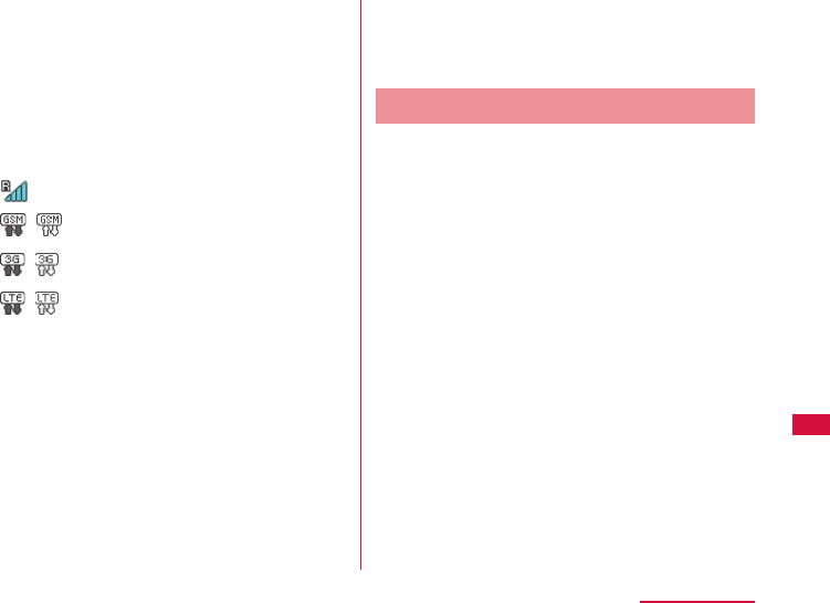
119
Overseas Use
• " 圏外 (Out of service)" is displayed when moved
out of the service area of the operator you set
up manually. To reuse the service, you need
to either search the connectable operators in
"Searching network" and select one, or move
to the service area of the operator you set.
■ About screen display
• The network type in use is displayed on the
status bar.
Roaming
/GSM available/
communicating
/3G available/
communicating
/LTE available/
communicating
• You can check the connected network
operator name on notifi cation panel.
■ Inquiries
• If this terminal or docomo mini UIM card is
lost or stolen overseas, contact DOCOMO
immediately from your current location and
carry out the procedures to suspend usage.
For contact information, refer to the back
cover of this manual. Note that you are liable
for charges incurred for communication after
the loss or theft of this terminal.
• You will need the country's "international
call access code" or "universal number
international prefi x" if calling from a land-line
phone overseas.
After Returning to Japan
When you return to Japan, this terminal
automatically connects to docomo network. If
it is unable to connect, change the following
settings.
• Set "Searching network" to "Auto". ( → P111)

120
Overseas Use
Settings for using overseas
At the time of purchasing, it is set to
automatically search and connect to an
available network. When changing to another
network manually, follow the operations below
to set up.
The same setting can be operated in setting
menu. (→P111)
Setting Network Search
a Log in to the setting page
For details, refer to "Logging in to the
Setting Page (L-01G Connection Manager)"
(→P77).
b Click "MOBILE NETWORK" on the top
menu
c Click "Searching network" on the sub
menu and set the items
Searching mode
Select if you want to specify an access point
or not.
• Auto: The connectable network is selected
automatically.
• Manual: Select it if you want to specify an
access point. Click "Apply" to search the
connectable network, and it is displayed in
"Operators".
■ Setting manually
Operators
Select a network to connect.
d Click "Apply" to save the settings
121
Overseas Use
Setting Network Mode
a Log in to the setting page
For details, refer to "Logging in to the
Setting Page (L-01G Connection Manager)"
(→P77).
b Click "MOBILE NETWORK" on the top
menu
c Click "Network mode" on the sub
menu and set the items
Network mode
Select an access point base on the area you
use
• 3G/GSM: Select automatically from 3G
network and GSM/GPRS network and start
use.
• 3G: Use only 3G network.
• GSM: Use only GSM/GPRS network.
d Click "Apply" to save the settings
Note
• Using overseas
- Some services are not able to use
depending on the overseas operator or the
network you use.

122
Charging Mobile Devices
Charging Mobile Device
Charging Mobile Device
Attaching
a Press the power button of this
terminal for over two seconds
This terminal is turned on.
b Insert the microUSB connector of
the supplied Converter Cable for
Charging L02 into the external
connection terminal of this terminal
with the USB mark facing up
c Insert the USB connector of the
supplied USB cable L03 into the USB
connector of the supplied Converter
Cable for Charging L02 with the USB
mark facing up
d Confi rm the orientation of the
microUSB connector of the USB
cable L03 and insert it into the
microUSB connection terminal of the
mobile device
123
Charging Mobile Devices
• 40%
• 20%
• 0% (Only displayed when "Charging Only"
is selected)
Note
• Depending on the usage environment, this
terminal may become warm which may result
in power supply suspension.
• When "Charging with using network" is
selected, "0%" in "Select Battery Limit" is set
to unable to choose to ensure the remaining
battery for possible communication. Also we
recommend "Charging Only" since "Charging
with using network" causes large consumed
power and results in high temperature.
• When it attempts to charge even if charging
current is excess, the protecting circuit of
the battery pack on this terminal will function
automatically and power off this terminal. In
that case, remove the battery pack of this
terminal and attach it again before turning it
on.
• When inserting or removing the connector,
confi rm the orientation (both sides) and
insert or remove horizontally. Putting
excessive force to remove it may result in
malfunction.
e Select charging mode on the display
of this terminal and tap "OK"
Charging of the mobile device starts.
is displayed and the LED indicator is
fl ashing red for fi ve seconds.
Charging Only
Stop the network service and charge the
mobile device.
Charging with using network
Network service can be used while charging
the mobile device.
• "Charging with using network" cannot
be selected without full charge of this
terminal.
Select Battery Limit
When remaining battery is less than the
value you specifi ed, power supply stops.
• 80%
• 60%

124
Charging Mobile Devices
Removing
a Remove USB cable L03 from the
mobile device and Converter Cable
for Charging L02
b Remove Converter Cable for
Charging L02 from this terminal
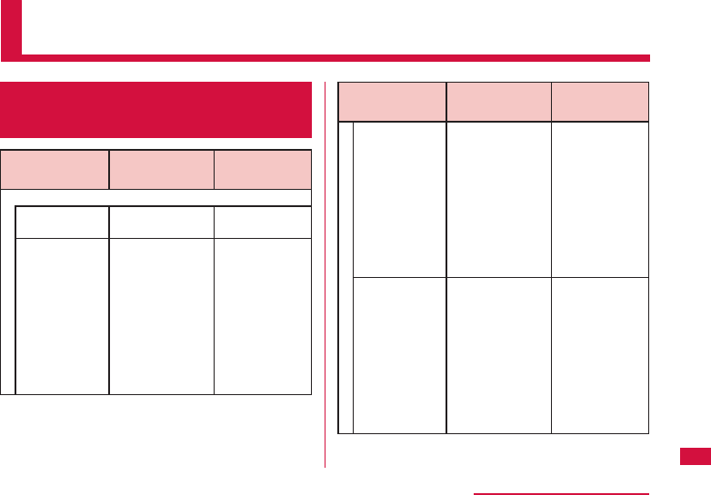
125
Appendix/Troubleshooting
Appendix/Troubleshooting
L-01G Connection Manager
menu item setting item list
Menu item/
setting item Default value Setting
range
Provider
Profi le
selection
mopera U -
Profi le name mopera U Up to 15
characters of
single byte
alphanumeric
characters and
single byte
space, symbols
(~ ! @#$%^&*-
_:、。/;|()<>{}[]+=`
? `"\)
Menu item/
setting item Default value Setting
range
Access point
name
mopera.net Up to 99
characters of
single byte
alphanumeric
characters and
single byte
space, symbols
(~!@#$%^&*-
_:、。/;|()<>{}[]+=`?
‘“\)
Username (None) Up to 64
characters of
single byte
alphanumeric
characters and
single byte
space, symbols
(~!@#$%^&*-
_:、。/;|()<>{}[]+=`?
‘“\)
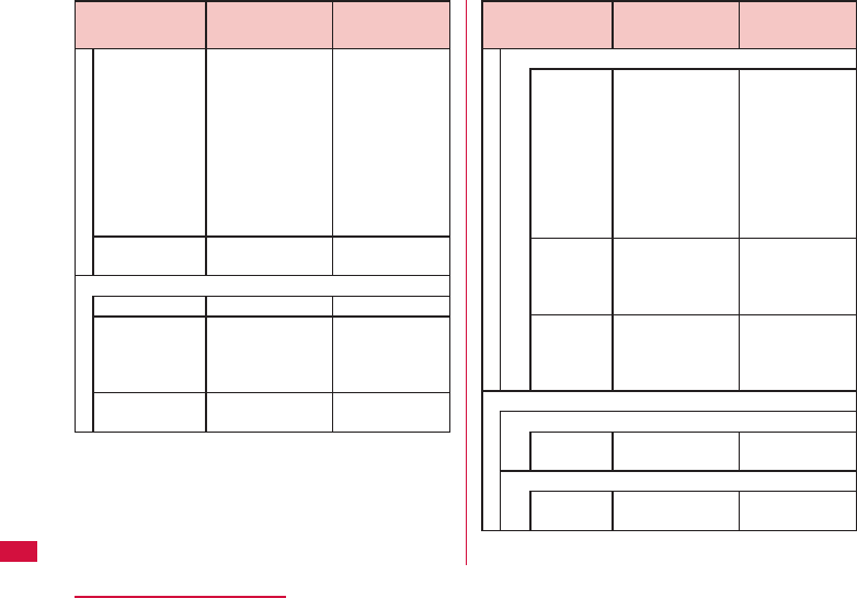
126
Appendix/Troubleshooting
Menu item/
setting item Default value Setting
range
Password (None) Up to 32
characters of
single byte
alphanumeric
characters and
single byte
space, symbols
(~!@#$%^&*-
_:、。/;|()<>{}[]+=`?
‘“\)
Authentic
method
CHAP CHAP, PAP,
None
Public WLAN
Public WLAN Off On, Off
Display mode Used networks Used
networks,
Registered
networks
Network
notifi cation
Off On, Off
Menu item/
setting item Default value Setting
range
Add new WLAN access point
AP name (None) Up to 32
characters of
single byte
alphanumeric
characters and
symbols (~!
@#$%^&*-_:、。
/;|()<>{}[]+=`?
‘“\)
Security Open Open, WEP,
WPA/WPA2-
PSK, EAP-SIM,
EAP-AKA
Password (None) Able to change
depending
on security
setting
MOBILE NETWORK
Searching network
Searching
mode
Auto Auto, Manual
Network mode
Network
mode
3G/GSM 3G/GSM, 3G,
GSM
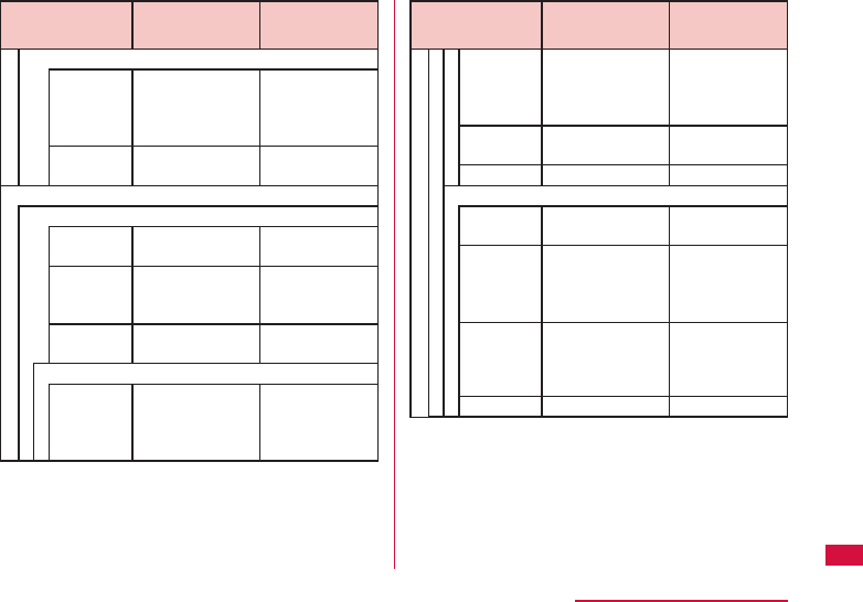
127
Appendix/Troubleshooting
Menu item/
setting item Default value Setting
range
Network data usage
Current
data
usage
Used data only Used data
only, Used
data with max
data, Off
Maximum
data size
0 1 to 99
Wi-Fi
Basic setting
Frequency
band
2.4 GHz 2.4 GHz
SSID/Key
Display on
modem
On On, Off
Privacy
separator
Off On, Off
2.4GHz setting
Channel Auto Auto, 1, 2, 3,
4, 5, 6, 7, 8,
9, 10, 11, 12,
13
Menu item/
setting item Default value Setting
range
IEEE802.11
Mode
11b/g/n 11b only, 11b/
g, 11g only,
11n only, 11b/
g/n
WLAN
Bandwidth
20/40 MHz 20 MHz,
20/40 MHz
MIMO On On, Off
5GHz setting
Channel Auto Auto, 36, 40,
44, 48
IEEE802.11
Mode
11a/n/ac 11a only, 11n
only, 11ac
only, 11a/n,
11a/n/ac
WLAN
Bandwidth
20/40/
80MHz
20MHz
20/40 MHz
20/40/80MHz
MIMO On On, Off
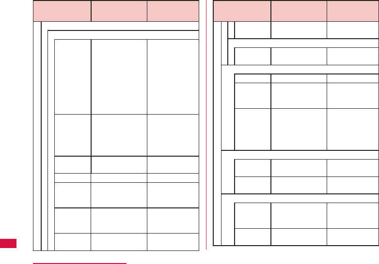
128
Appendix/Troubleshooting
Menu item/
setting item Default value Setting
range
SSID setting
Primary SSID
SSID L01G_
XXXXXXXX_A
Up to 32
characters of
single byte
alphanumeric
characters
and symbols
(~`!@#$%^&*()-
_+={}
[]|\:;"'<>,.?/)
Security WPA/WPA2-
PSK mixed
Open, WEP,
WPA-PSK,
WPA2-PSK,
WPA/WPA2-
PSK mixed
Encryption
type
TKIP/AES TKIP/AES,
AES, TKIP
Password XXXXXXXX -
Key
update
cycle(sec)
86400 0 to 86400
Max
number of
clients
9 1, 2, 3, 4, 5, 6,
7, 8, 9, 10
AP
isolation
Off On, Off
Menu item/
setting item Default value Setting
range
SSID
Stealth
Off On, Off
Secondary SSID
Secondary
SSID
Off On, Off
Wi-Fi Protected Setup (WPS)
WPS On On, Off
WPS type Button Button, PIN
(From AP), PIN
(From client)
PIN (None) (enter the
issued PIN
on Wi-Fi
compatible
device side)
MAC address fi lter
Restrict
mode
Off Off , Allow,
Deny
MAC
addresses
(None) (MAC address)
DHCP
IP
address
192.168.225.1
IP address
available to
set
Subnet
mask
255.255.255.0
255.255.255.0 to
255.255.255.254
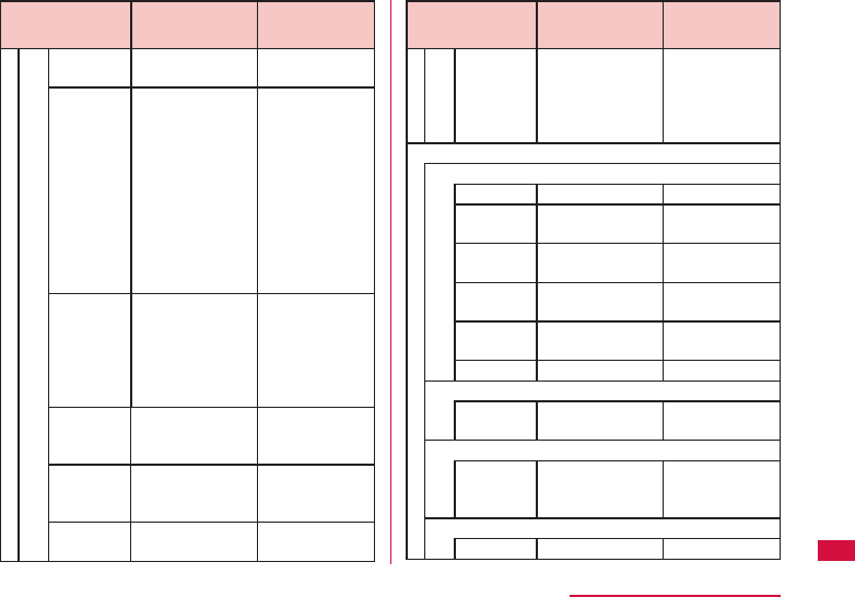
129
Appendix/Troubleshooting
Menu item/
setting item Default value Setting
range
DHCP
server
On On, Off
Start IP
address
192.168.225.20
From fi rst to
third octet IP
address of
DHCP server
is same. The
fourth octet
is values
excluded the
IP address of
DHCP server
from 1 to 254.
End IP
address
192.168.225.40
Same as Start
IP address
However, a
bigger value
than Start IP
address
Primary
DNS
0.0.0.0
IP address
available to
DNS
Secondary
SSID
0.0.0.0
IP address
available to
DNS
MTU
(byte)
1500 578 to 1500
Menu item/
setting item Default value Setting
range
Add static
DHCP
(None) (MAC address,
values from
Start IP
address to End
IP address)
ROUTER
Firewall
Firewall Off On, Off
Internet IP
address
(None)
0.0.0.1 ∼
255.255.255.254
LAN IP
address
(None)
0.0.0.1 ∼
255.255.255.254
Direction Internet->LAN
Internet->LAN,
LAN->Internet
Protocol All All, TCP, UDP,
ICMP, Manual
Policy Accept Accept, Ignore
WAN ping blocking
WAN ping
blocking
Off On, Off
IDENT
IDENT
packet
handling
Block Accept, Block
DMZ
DMZ Off On, Off
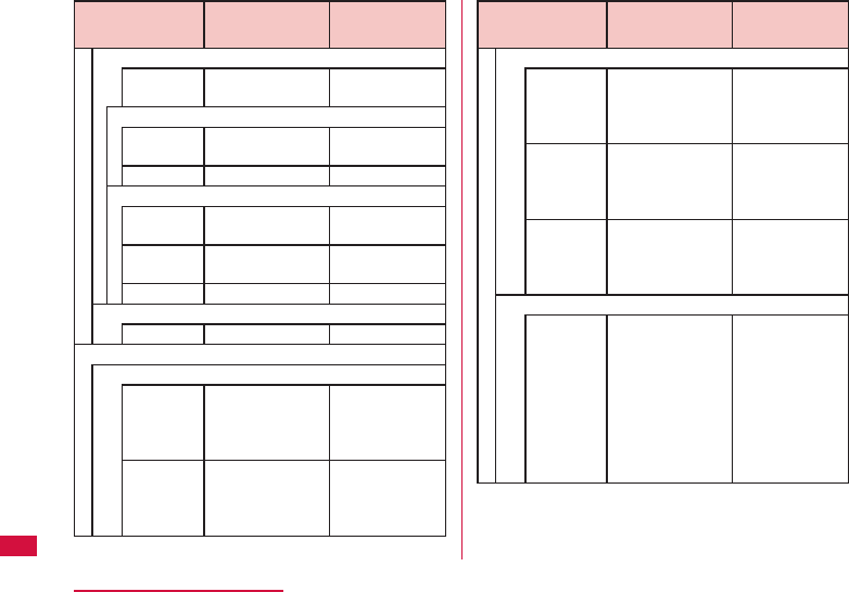
130
Appendix/Troubleshooting
Menu item/
setting item Default value Setting
range
Modify
Current
PIN1
code
(None) Single byte
numbers of
4 digits to 8
digits
New PIN1
code
(None) Single byte
numbers of
4 digits to 8
digits
Confi rm
PIN1
code
(None) Single byte
numbers of
4 digits to 8
digits
Modify password
Current
password
(None) Up to 4 to 32
characters of
single byte
alphanumeric
characters and
symbols (~!
@#$%^&*-_:、。
/;|()<>{}[]+=`?
‘“\)
Menu item/
setting item Default value Setting
range
Port mapping
Port
mapping
Off On, Off
From
Port
number
TCP TCP, UDP
(None) 1 to 65535
To
IP
address
(None)
0.0.0.1 ∼
255.255.255.254
Port
number
TCP -
(None) 1 to 65535
Universal Plug and Play (UPnP)
UPnP On On, Off
SYSTEM
PIN1 lock
PIN1
code to
set lock
(None) Single byte
numbers of
4 digits to 8
digits
PIN1
code to
set unlock
(None) Single byte
numbers of
4 digits to 8
digits
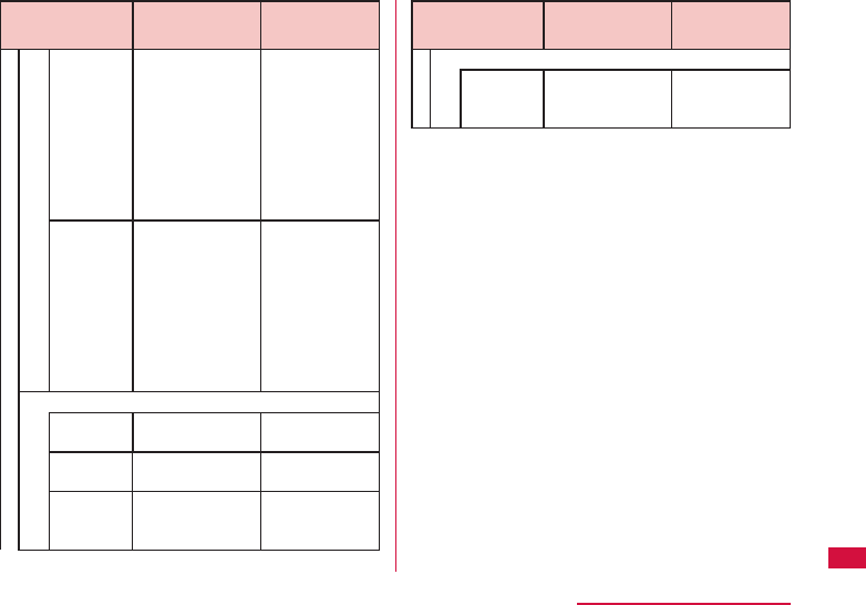
131
Appendix/Troubleshooting
Menu item/
setting item Default value Setting
range
New
password
(None) Up to 4 to 32
characters of
single byte
alphanumeric
characters and
symbols (~!
@#$%^&*-_:、。
/;|()<>{}[]+=`?
‘“\)
Confi rm
password
(None) Up to 4 to 32
characters of
single byte
alphanumeric
characters and
symbols (~!
@#$%^&*-_:、。
/;|()<>{}[]+=`?
‘“\)
Wi-Fi Power control
Auto off
timer(min)
10 Never, 10, 30,
60
DTIM period
(100ms)
1 1, 2, 3, 4, 5, 6,
7, 8, 9, 10
Transmit
strength
100% 100%, 75%,
50%, 35%,
15%
Menu item/
setting item Default value Setting
range
AP operation mode
AP
operation
mode
Router Router, Bridge

132
Appendix/Troubleshooting
Introduction of Options
and Related Devices
You can use this terminal for both personal
and business purposes through combining
with diff erent optional devices. Some products
may not be able to purchase in some certain
areas. For details, contact a service counter
such as a docomo Shop.
For details about options, refer to the related
instruction manuals.
• Back cover LXX
• Battery Pack LXX
• AC Adapter L04
• AC Adapter L03
• AC Adapter L02
• USB Cable L03
• USB Cable L02
• USB Cable L01
• Converter Cable for Charging L02
• Pocket Charger 02
• Pocket Charger 01
• AC Adapter 04
• AC Adapter 03
• DC Adapter 03
• AC Adapter Converter Plug TypeC 01
• MicroUSB Cable 01
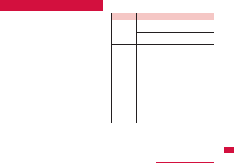
133
Appendix/Troubleshooting
Troubleshooting
First, check whether software update
is necessary. If so, update the software
(→P145 "Updating Software").
If it does not improve after confi rming the
check items, contact "Repairs" (in Japanese
only) on the back cover of this manual or a
repair counter specifi ed by DOCOMO.
■ Power, charging and mobile device charging
related
Symptom Check item
Cannot
power on
Is battery pack inserted correctly?
(→P33)
Is the battery dead?
(→P44, P41, P53)
Cannot
charge
LED
indicator
does not
light up
Confi rm the following things.
• Is battery pack inserted correctly?
(→P33)
• Is the power plug of adapter
inserted into outlet correctly?
(→P41)
• Are the adapter and this terminal
set properly? (→P41)
• When using the AC adapter
04, is the USB connector fi rmly
connected to this terminal?
(→P41)
• When using the supplied USB
Cable L03, is the PC powered on?
(→P53)
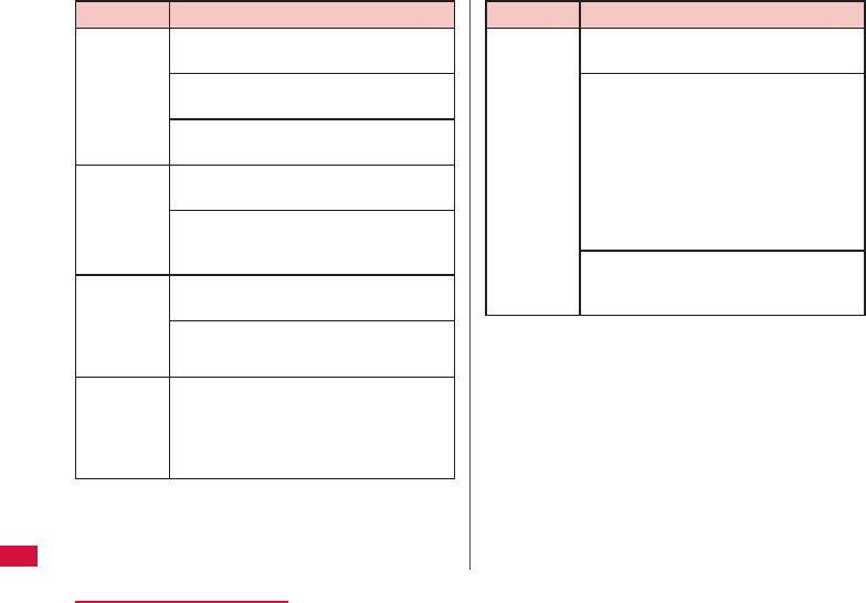
134
Appendix/Troubleshooting
Symptom Check item
Cannot
charge
mobile
device
Is the specifi ed cable used?
(→P122)
Is the cable inserted into mobile
device? (→P122)
Has this terminal been charged?
(→P39)
Charging
time of
the mobile
device is
short
Is the specifi ed cable used?
(→P122)
When charging the battery pack
of mobile device with battery left,
charging time becomes short.
Charging
time of
the mobile
device is
long
Is the specifi ed cable used?
(→P122)
Is the mobile device powered on?
Charging
of the
mobile
device
stopped
Is it charged with the low battery of
this terminal? Charge this terminal
fi rst. ( →P39)
Symptom Check item
Even
when this
terminal is
charged
fully, the
mobile
device is
not fully
charged
Is the specifi ed cable used?
(→P122)
Battery pack is a consumable
supply. When consuming time
becomes short even when it is fully
charged, it is time to replace the
battery pack. Please purchase a
new batter pack.
* The replacement time of the
battery pack diff ers depending on
the usage conditions.
Depending on the mobile device, it
may not be able to charge fully. For
details, visit DOCOMO website.
135
Appendix/Troubleshooting
■ Terminal operations related
Symptom Check item
Becomes
hot during
operating
or
charging
It is normal that the adapter
becomes warm during operating or
charging. You can continue using
without problems.
Symptom Check item
Battery life
is short
Confi rm the following things.
(→P39)
• Has this terminal been out of the
network service area for a long
time?
As this terminal searches for
radio waves in order to enable
communication when out of the
network service area, more battery
is consumed than usual.
• Battery life may diff er depending
on the use environment or
degradation level.
• Battery pack is a consumable
supply. Every time when you
charge the battery, usable time
becomes short.
When usage time becomes
extremely short compared with
the new one you purchased even if
it is fully charged, purchase a new
specifi ed one.
Power is
disconnected/
restart
Power may turn off when the
terminal of the battery pack is soiled
or when the connection is not good.
If so, wipe the terminal of the battery
pack by using a dry cotton swab.
136
Appendix/Troubleshooting
Symptom Check item
docomo
mini UIM
card is not
recognized
Is docomo mini UIM card inserted in
the right direction? (→P33)
■ This terminal is not recognized
Symptom Check item
This
terminal
is not
recognized
by the PC
connect
via USB
Cable L03
Connect with another USB port and
confi rm again.
Confi rm if this terminal is connected
correctly with a PC via the supplied
USB Cable L03.
Remove the USB Cable L03 from
the PC and restart the PC, then
connect again.
Symptom Check item
This
terminal
is not
recognized
by the PC
connect
via USB
Cable L03
L-01G Uninstall the driver and
connect again.
■ How to uninstall driver
■ For Windows 8.1
a
On the desktop screen, →
"Control Panel" → "Programs"
→ "Programs and Features"
• For Windows 8, on the
desktop screen, swipe from
the right side of the screen
(point the top right of the
screen in case of mouse) →
from charm, click "Search"
→ "Apps" → "Control Panel"
→ "Programs" → "Programs
and Features"
• "Uninstall or change
a program" window is
displayed.
b
Select "docomo L01G" and
click "Uninstall"
c
Click "Yes"
d
Make sure that "Clear
communication settings
(W-TCP setting)
(Recommended)" is selected
and click "Next"
e
Click "Finish"
137
Appendix/Troubleshooting
Symptom Check item
This
terminal
is not
recognized
by the PC
connect
via USB
Cable L03
■ For Windows 7
a
Click (Start) → "Control
Panel" → "Programs" →
"Program and Features"
• "Uninstall or change
a program" window is
displayed.
b
Select "docomo L01G" and
click "Uninstall"
c
Click "Yes"
d
Make sure that "Clear
communication settings
(W-TCP setting)
(Recommended)" is selected
and click "Next"
e
Click "Finish"
■ For Mac OS X 10.9.1
a
Click "Go" → "Applications"
b
Click "L-01G UnInstaller"
c
Click "Uninstall"
d
Enter the Mac name (user
name) and password, and
click "OK"
e
Click "Restart" on the
installation complete screen
■ Wi-Fi function related
Symptom Check item
Cannot
connect
to Wi-Fi
compatible
device
Confi rm if the Wi-Fi function on this
terminal and the Wi-Fi compatible
device is turned on.
Confi rm if the correct security key is
set in the Wi-Fi compatible device.
(→P60)
When you forget the security key
set in this terminal, refer to "Setting
Security Mode of Wireless LAN"
(→P90) to change the security
key and connect again.
138
Appendix/Troubleshooting
Symptom Check item
Cannot
connect
to Wi-Fi
compatible
device
When this terminal is set to a
security mode other than WPA/
WPA2-PSK mixed, the same setting
is necessary on the Wi-Fi compatible
device to be connected. For details,
refer to the instruction manual of
the Wi-Fi compatible device you use.
■ Example when security mode is
WEP (for Windows 8.1)
On the desktop screen, →
"Control Panel" → "Network and
Internet" → "Network and Sharing
Center" → click the name of this
terminal in "Connections:" of "View
your active networks" → "Wireless
Properties" → "Security" tab → set
as follows
• Security type: No authentication
(Open)
• Encryption type: WEP
• Network security key: the WEP
key set in this terminal by the
number selected in [Key index]
Symptom Check item
Cannot
connect
to Wi-Fi
compatible
device
■ Example when security mode is
WEP (for Mac OS X 10.9.1)
"Apple" menu → "System
Preferences" → "Network" →
select "Wi-Fi" on the left of the
screen → "Edit Locations..." in
"Locations" → "+" → enter any
name in "Untitled" → "Done" →
mark "Show Wi-Fi status in menu
bar" → "Advanced..." → select "Wi-
Fi" on the top of the screen → "+
" → enter network name → select
"WEP" in "Security" → enter the
WEP key set in this terminal in
"Password" → "OK" → "OK" → when
"Off " is displayed, mark "Turn Wi-Fi
On", "Apply"
When it cannot be connected
via WPS function, refer to the
instruction manual of the Wi-Fi
compatible device you use and
confi rm the settings of the WPS
function on this terminal (→P93
"Setting WPS function"), then
connect again.
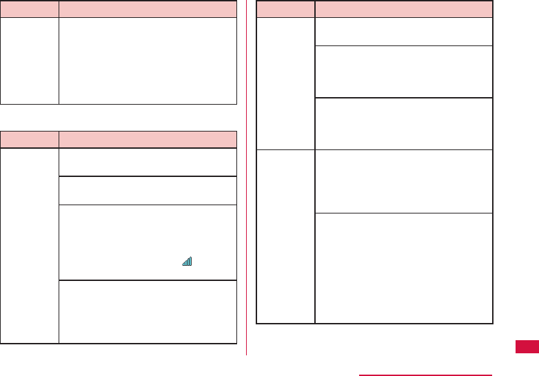
139
Appendix/Troubleshooting
Symptom Check item
Cannot
connect
to Wi-Fi
compatible
device
When connecting with the Wi-Fi
compatible device with PIN code
for WPS specifi ed, confi rm if "WPS
PIN" is selected in the WPS function
settings (→P93 "Setting WPS
function") on this terminal, and
confi rm if PIN code is set correctly.
■ Communicating related
Symptom Check item
Cannot
communicate
Confi rm if the signal is received
within the service area
Power on again, or insert the battery
pack or docomo mini UIM card again.
Depending on the type of radio
waves, you may not be able to make
communication with state of "it is
not out of service" or "Signal
reception is displayed as ". Move
to another place and confi rm again.
If a password is set for docomo
mini UIM card, when this terminal
is powered on or when the setting
page is logged in, enter PIN1 code.
(→P43, P79)
Symptom Check item
Cannot
communicate
Confi rm the settings of this terminal
and the APN registration.
You may not be able to access to
the Internet depending on the signal
condition. In this case, turn off this
terminal and turn on again.
When accessing to the Internet
via this terminal, make sure that
other communication devices are
disconnected.
Internet
speed
becomes
slow
immediately
For service environment of LTE/
W-CDMA/HSDPA/HSUPA/GSM/
GPRS located in unsteady areas,
speed becomes slow. Move to
another place and connect again.
When communicating on Windows
PC, optimization of the PC
communication setting is necessary.
Connect this terminal with a PC
via the supplied USB Cable L03
and install the driver. Confi rm if
"Optimize communication settings
(W-TCP Setting) (Recommended)" is
selected.
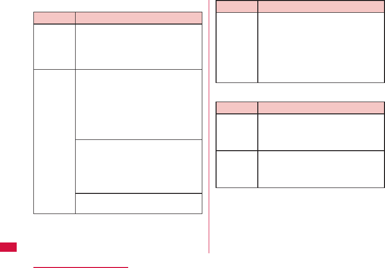
140
Appendix/Troubleshooting
■ Overseas usage related
Symptom Check item
Cannot
communicate
overseas
(Antenna
mark appears)
Have you applied for WORLD WING?
Check whether you have applied for
WORLD WING.
Cannot
communicate
overseas
(Icon
indicates out-
of-service
area appears)
Are you at a location outside of the
international roaming service area,
or a place where the signal is weak?
Use "Mobile Phone User's Guide
[International Services]" or DOCOMO
"International Services website" to
check whether a service area or
network operator is available.
Change the settings of network or
overseas network operator.
• Set "Searching mode" to "Manual".
(→P120)
• Confi rm the setting of
"PROVIDER". (→P82)
It may recover after turning off this
terminal and then turning it on again.
Symptom Check item
Communication
becomes
unusable
suddenly while
using overseas
Has the approximate limit of usage
fee been exceeded?
For "International roaming service
(WORLD WING)", the approximate
limit of usage fee is set in advance.
If the limit is exceeded, all services
are stopped. Pay off the usage fee
to resume services.
■ Other
Symptom Check item
Stop
operating
all of
sudden
Is docomo mini UIM card inserted
correctly into this terminal?
(→P33)
Back cover
is off
Align the back cover with the main
unit, press the arrow parts one by
one to close the back cover fi rmly.
(→P37)
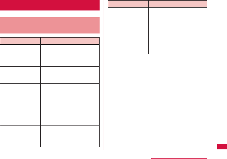
141
Appendix/Troubleshooting
Error message
Message Displayed in Setting
Page (L-01G Connection Manager)
Error Message Description
Incorrect
password entered
When logging in, the
password you entered is
wrong, Click "OK" and enter
the correct password.
Incorrect PIN1
code entered.
Please try again.
The PIN1 code you entered
is wrong. Click "OK" and
enter the correct PIN1 code.
Incorrect PIN1
code entered for 3
times.
Please enter PIN
unlock code.
PIN1 code is locked after
failing entering three times
in a row. Click "OK" and enter
PUK in "PIN unlock code".
Enter a new PIN1 code in
each item of "New PIN1
code" and "Confi rm PIN1
code" and click "Apply".
Incorrect PIN
unlock code
entered.
Please try again.
The PIN unlock code you
entered is wrong. Click "OK"
and enter the correct PIN
unlock code.
Error Message Description
L-01G is locked
because user
failed to input
correct PIN unlock
code for 10 times.
Please contact
DOCOMO shop
or DOCOMO
information center.
If you fail entering the
correct PIN unlock code ten
times, the docomo mini UIM
card will be locked. Contact
a docomo Shop.
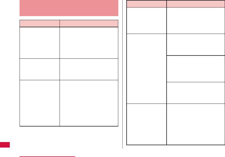
142
Appendix/Troubleshooting
Message Shown on the Display
of this Terminal
Error Message Description
Secondary SSID is
set.
Please turn
secondary SSID
off to use Public
WLAN function.
When using public
wireless LAN, set
"Secondary SSID" to "Off " in
L-01G Connection Manager.
(→P92)
Pocket Charging is
unavailable.
Because battery is
too low.
Charge this terminal fi rst.
(→P39)
L-01G is locked
because user
failed to input
correct PIN unlock
code for 10 times.
Please contact
DOCOMO shop
or DOCOMO
information center.
If you fail entering the
correct PIN unlock code ten
times, the docomo mini UIM
card will be locked. Contact
a docomo Shop.
Error Message Description
PWLAN is not
available because
Wi-Fi is off . To use
PWLAN , turn Wi-Fi
on First.
If Wi-Fi function is turned
off , public wireless LAN
cannot be used. Turn on Wi-
Fi function fi rst. ( →P45)
WPS function
is not available
under the following
conditions.
• Security type is
WEP or WPA
• Encryption type
is TKIP
• SSID stealth is
on
When "Security" is set to
"WEP", WPS function cannot
be used. Change "Security"
in setting page. (→P90)
When "SSID Stealth" is
set to "On", WPS function
cannot be used. Change
"SSID Stealth" in setting
page. (→P91)
When "Security" is set to
"WEP" and "SSID Stealth" is
set to "On", WPS function
cannot be used. (→P91)
No more clients
can be connected.
Please check the
maximum numbers
of clients
When it reaches the top
number of the devices which
can be connected to primary
SSID, WPS function cannot
be used.
Confi rm the maximum
number of the connection of
primary SSID. (→P91)

143
Appendix/Troubleshooting
Warranty and After-Sales
Service
Warranty
• Be sure to receive a warranty at the time of
purchase of this terminal. Read contents of
the warranty and confi rm information such as
"販売店名・お買い上げ日 (shop name and date
of purchase)" and keep it in a safe place. If
necessary items are not described, immediately
contact the shop of purchase. The warranty for
free repair is valid for one year from the date of
purchase.
• This product and its accessories are subject
to modifi ed, in part or whole, for improvement
without prior notice.
After-Sales Service
When this terminal breaks down
• Before requesting repairs, read "Troubleshooting"
in this instruction manual. If the problem still
persists, contact "Repairs" (in Japanese only) on
the back of this manual.
Repairs
Bring your terminal to a repair counter
specifi ed by DOCOMO. Repairs are accepted
during business hours of a repair counter.
Also, you must bring the warranty. Note that
it may take some days to repair this terminal
depending on the malfunction state.
■ During the warranty period
• This terminal is repaired at no charge under
the conditions of the warranty.
• Make sure to bring the warranty for repair.
You will be charged even during the warranty
period if the warranty is not presented or
the trouble or damage is caused by your
inappropriate handling (such as damage of
display or connector, etc.).
• You will be charged even during the warranty
period if malfunction is caused by the use of
devices and consumables other than those
specifi ed by DOCOMO.
■ Repair may not be possible in the following
cases.
• When, as the result of inspection, corrosion is
found due to exposure to water, condensation
or sweat, or any of the internal boards are
damaged or deformed (damage of the external
connection terminal, display or cracked body
could be the case as well).

144
Appendix/Troubleshooting
* Since these conditions are outside the scope
of the warranty, any repairs, if at all possible,
will be charged.
■ After expiration of the warranty
All repairs that are requested are charged.
■ Replacement parts
Replacement parts (parts required to
maintain functions) will in principle be kept
in stock for 4 years after termination of
production. However, depending on the
malfunctioning part, repair may not be
possible due to a lack of replacement parts.
Even after the stock period has expired, the
repair of some malfunctioning parts may
be possible. Therefore contact "Repairs" (in
Japanese only) on the back of this manual.
Precautions
• Never modify this terminal or accessories.
- Doing so may result in fi re, injuries or
malfunctions.
- The modifi ed terminal may be repaired only
if the owner agrees on that all the modifi ed
parts are restored to the original conditions.
However, repairs may be refused depending on
the modifi cations.
The following cases may be considered as
modifi cations.
• Put stickers on the display or button part
• Glued decorations on this terminal using
adhesion bond, etc.
• Change the parts such as exterior to other
than DOCOMO standard parts.
- Malfunction and damage due to modifi cations
will be repaired at the owner's expense even
during the warranty period.
• Do not take off the nameplate pasted on this
terminal. Nameplate is a certifi cate proofs that
the technical standards meet the demand. If the
content of a nameplate cannot be confi rmed
when it is taken it off or replaced it on purpose,
repair is not acceptable due to the impossibility
of technical standards judgment.
• Note that the settings and other information
may be cleared (reset) as a result of malfunction,
repair or other handling. In this case, make the
settings again.
• When the repair is executed, MAC address,
security key, SSID, etc. for Wireless LAN in this
terminal may be changed regardless of repaired
part.
• If this terminal has gotten wet or moist,
immediately power off this terminal and remove
the battery pack, then bring it to the DOCOMO-
specifi ed repair offi ce as soon as possible.
However, note that it may not be repaired
depending on the extent of the damage.

145
Appendix/Troubleshooting
Updating Software
Software Update is a function that connects
to the network to check whether software on
this terminal needs to be updated, downloads
the software when required, and updates the
software.
The NTT DOCOMO website provides
information about required software updates.
There are two methods of checking the
software update as shown below.
• When there is a latest update, "New software
version is available. Update it now?" is displayed
on this terminal.
• Check manually if there is a software to update.
("Confi rming Software Update" ( →P146))
Before Updating Software
• Do not remove the battery pack while updating
software. This may result in a failed update.
• Fully charge the battery before updating
software. Connecting the charging cable is
recommended while updating.
• Software cannot be updated in the following
circumstances.
- While communicating
- When docomo mini UIM card is not inserted
- When "out of service" is displayed
- During international roaming
- When it cannot be powered on
- When the date or time has not been set
correctly
- When the battery level is too low for software
update
* While you are out of the service area or using
overseas roaming, update is not available
even Wi-Fi is connected.
• Software update (download, installation) may
take time.
• During a software update, you cannot use
communication function and other functions.
• We recommend that you update software
without moving and when you have strong
reception. Software update may be interrupted in
146
Appendix/Troubleshooting
a place with bad reception.
• When the software has already been updated,
"Latest version." is displayed when checking the
software update.
• During software update, data charge may occur
depending on the charge plan you registered.
• During a software update, your L-01G
information (model and manufacturing numbers)
are automatically sent to a software update
server managed by DOCOMO. DOCOMO shall
not use this information for any purpose other
than software update.
• When software update fails, all operations may
become unavailable. In this case, please take
this terminal to a repair counter specifi ed by
DOCOMO.
• If a PIN has been set, the PIN entry screen
appears during the restart after rewriting and
you are required to enter your PIN.
• During software update, data communication
may be charged depending on the charge plan
you used.
Confi rming Software Update
a From the Home screen, " "
b "Software update"
c "Check now for update"
Software update screen is displayed.
Later
Return to the software update screen.
"" icon is displayed to show that there is a
new software.
Update
Software update starts. Follow the on-screen
instructions.
147
Appendix/Troubleshooting
Setting Download Method
a From the Home screen, " "
b "Software update"
c "Download setting"
Download setting screen is displayed.
Via any network
Download when the Internet is connected by
all means including data communication.
Via Wi-Fi/Wired port
Download only when connecting via Wi-Fi or
wire LAN.
Updating Software
Update software by the following operations
when a message appears to show the update
notifi cation.
Note
• When software is updated, setting data is
changed to default. To remain the setting
data, set to "Backup & Restore" in setting
page. (→P105)
a When a message appears to show
there is a update notifi cation, "Update"
b "OK"
Software download starts and software is
updated. This terminal restarts once or twice
during installation.
c When the software update is
completed, "OK"
148
Appendix/Troubleshooting
Resetting this Terminal
Follow the operations below to reset this
terminal to the default settings. However,
data communication amount displayed on the
display is not reset.
For details about resetting data
communication amount, refer to "Displaying
Data Communication Amount" (→P86).
a From the Home screen, " "
b "System"
c "Reset"
Confi rmation screen is displayed.
d "Yes"
This terminal is reset.
Main Specifi cations
■ Terminal
Model name L-01G
Size (H×W×D) Approx. 97 mm × Approx.
62 mm × Approx. 19.5 mm
(Max. thickness : Approx. 19.5
mm)
Weight Approx. 156 g (with battery
pack attached)
Continuous
communication
time
LTE Approx. 13 hours
3G
(HSDPA/
HSUPA,
W-CDMA)
Approx. 16 hours
GSM Approx. 12 hours
Continuous
standby
time
LTE Approx. 450 hours
3G
(HSDPA/
HSUPA,
W-CDMA)
Approx. 550 hours
GSM Approx. 700 hours
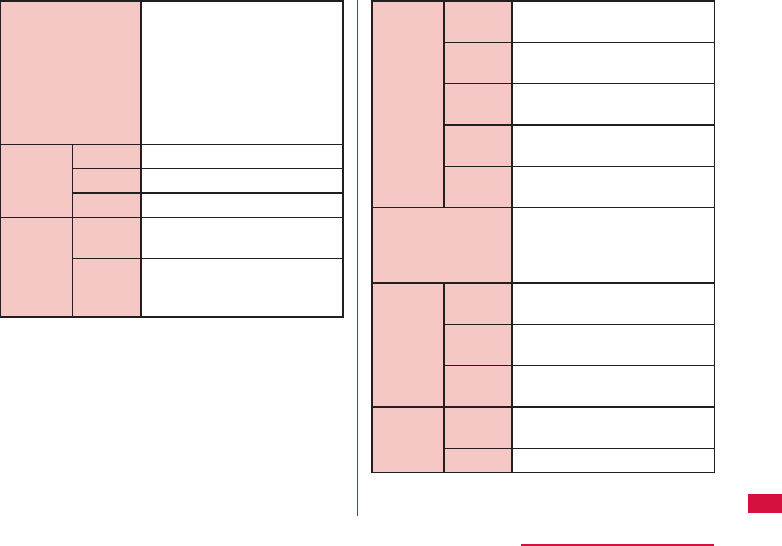
149
Appendix/Troubleshooting
Charging time AC adapter 03: approx. 300
minutes
AC adapter 04: approx. 210
minutes
DC adapter 03: approx. 360
minutes
USB Cable L03: approx.
360 minutes
Screen
part
Type TFT
Size Approx. 3.0 inch
Pixels 240 dots×320 dots QVGA
Communication
form
WAN LTE/HSDPA/HSUPA/
W-CDMA
Wireless
LAN
IEEE802.11a/b/g/n/ac
(IEEE802.11n frequency
band: 2.4 GHz)
Wireless
LAN
compatible
standard
IEEE
802.11a
max. transmission speed
(standard) 54 Mbps
IEEE
802.11b
2.4 GHz, max. transmission
speed (standard) 11 Mbps
IEEE
802.11g
2.4 GHz, max. transmission
speed (standard) 54 Mbps
IEEE
802.11n
max. transmission speed
(standard) 300 Mbps
IEEE
802.11ac
max. transmission speed
(standard) 867 Mbps
Communication
speed*1*2*3*4
*5*6
Packet communication:
Max. 150 Mbps*7 for
receiving
Max. 50 Mbps*7 for sending
Compatible
frequency
band
LTE 2 GHz, 1.7 GHz, 1.5 GHz,
800 MHz
3G 2 GHz, 800 MHz, new 800
MHz
GSM/
GPRS
850 MHz, 900 MHz, 1800
MHz, 1900 MHz
Power
supply
function
Power
voltage
DC 5V
Current Rated 1.5A/max. 1.8 A
150
Appendix/Troubleshooting
*1 The communication speed is the maximum
value of sending and receiving data based
on the technical standard. It is not the
real communication speed. The speed is
provided by the best eff ort method. The real
communication speed changes depending
on the communication environment and the
network congestion situation.
*2 For the FOMA HIGH-SPEED area outside of Xi
area, maximum speed for sending is 14 Mbps,
and 5.7 Mbps for receiving.
*3 Speed of transferring may become 384 kbps
maximum even within FOMA HIGH-SPEED
area depending on the places.
*4 For FOMA area outside of both Xi area and
FOMA HIGH-SPEED area, maximum speed for
both sending and receiving is 384 kbps.
*5 The standard communication speed
based on the bandwidth of Xi area is,
receiving speed (bandwidth "20/15/10/5
MHz"): 150/110/75/37.5 Mbps, sending
speed (bandwidth "20/15/10/5 MHz"):
50/37.5/25/12.5 Mbps.
*6 For details about Xi compatible areas, please
visit DOCOMO website.
*7 Only a part of Xi areas.
• Continuous communication time is an estimate
of the battery life in case of a continuous call
with normal signal reception.
• Continuous standby time is an estimate
of the battery life in case of a continuous
standby with normal signal reception. In certain
circumstances, the standby time may drop to
as low as half the shown time in case of battery
charge, function settings, temperature, or radio
wave reception in the area (no reception or
weak).
• Data communication makes the communication
time and standby time become shorter.
• Charging time is an estimate of the time required
to charge a completely empty battery pack while
this terminal is turned off . The charging time is
longer if you charge while this terminal is turned
on.
■ Battery Pack
Model name Battery Pack LXX
Battery type Lithium-ion battery
Nominal
voltage
3.7 V
Nominal
capacity
3,600 mAh
■ JATE validation key
D13-0330001

151
Appendix/Troubleshooting
Export Administration
Regulations
Japan Export Control Regulations ("Foreign
Exchange and Foreign Trade Law" and
relevant laws and regulations) may apply to
this product and its accessories. U.S. Re-
export Regulations (Export Administration
Regulations) applies to this product and its
accessories. If you export or re-export this
product or its accessories, please follow
the necessary procedures at your own risk
and expense. For details on the procedures,
contact the Ministry of Economy, Trade and
Industry or the U.S. Department of Commerce.
Specifi c Absorption Rate
(SAR) of Mobile Terminals
This model L-01G complies with Japanese
technical regulations and international
guidelines regarding exposure to radio waves.
This terminal was designed in observance
of Japanese technical regulations regarding
exposure to radio waves (*1) and limits to
exposure to radio waves recommended by
a set of equivalent international guidelines.
This set of international guidelines was set
out by the International Commission on Non-
Ionizing Radiation Protection (ICNIRP), which
is in collaboration with the World Health
Organization (WHO), and the permissible limits
include a substantial safety margin designed
to assure the safety of all persons, regardless
of age and health condition.
The technical regulations and international
guidelines set out limits for radio waves as the
Specifi c Absorption Rate, or SAR, which is the
value of absorbed energy in any 10 grams of
tissue over a 6-minute period. The SAR limit for
mobile terminals is 2.0 W/kg. The highest SAR
value for this terminal when tested for intended
use described in the instruction manual is

152
Appendix/Troubleshooting
0.527W/kg (*2). There may be slight diff erences
between the SAR levels for each product, but
they all satisfy the limit.
The actual SAR of this terminal while operating
can be well below that indicated above. This is
due to automatic changes to the power level of
the device to ensure it only uses the minimum
required to reach the network. Therefore in
general, the closer you are to a base station,
the lower the power output of the device.
During communication, please keep the
terminal farther than 1.5 cm away from your
body without including any metals. This
terminal satisfi es the technical regulations and
international guidelines.
The World Health Organization has stated
that "a large number of studies have been
performed over the last two decades to assess
whether mobile phones pose a potential health
risk. To date, no adverse health eff ects have
been established as being caused by mobile
phone use."
Please refer to the WHO website if you would
like more detailed information.
http://www.who.int/docstore/peh-emf/
publications/facts_press/fact_english.htm
Please refer to the websites listed below if you
would like more detailed information regarding
SAR.
Ministry of Internal Aff airs and
Communications Website:
http://www.tele.soumu.go.jp/e/sys/ele/
index.htm
Association of Radio Industries and
Businesses Website:
http://www.arib-emf.org/index02.html
(in Japanese only)
NTT DOCOMO, INC. Website:
https://www.nttdocomo.co.jp/english/
product/sar/
LG Electronics Inc. Website (Check the
Specifi cations page for this terminal:
http://www.lg.com/jp/data-communication
(in Japanese only)
(the above URLs are subject to change for
without notice.)
*1 Technical regulations are defi ned by the
Ministerial Ordinance Related to Radio
Law (Article 14-2 of Radio Equipment
Regulations).
*2 Including other radio systems that can be
simultaneously used with Xi/FOMA.

153
Appendix/Troubleshooting
Declaration of Conformity
The product "L-01G" is declared to conform
with the essential requirements of European
Union Directive 1999/5/EC Radio and
Telecommunications Terminal Equipment
Directive 3.1(a), 3.1(b) and 3.2.
This wireless router complies with the EU
requirements for exposure to radio waves.
Your wireless router is a radio transceiver,
designed and manufactured not to exceed the
SAR* limits** for exposure to radio-frequency
(RF) energy, which SAR* value, when tested
for compliance against the standard was
0.431 W/kg at the body. To comply with the RF
Exposure limits a distance of greater than 1.5
cm must be maintained from the user's body.
While there may be diff erences between the
SAR* levels of various wireless routers and
at various positions, they all meet*** the EU
requirements for RF exposure.
* The exposure standard for wireless routers
employs a unit of measurement known as the
Specifi c Absorption Rate, or SAR.
** The SAR limit for wireless routers used by the
public is 2.0 watts/kilogram (W/kg) averaged
over ten grams of tissue, recommended by
The Council of the European Union. The limit
incorporates a substantial margin of safety to
give additional protection for the public and to
account for any variations in measurements.
*** Tests for SAR have been conducted using
standard operating positions with the
wireless router transmitting at its highest
certifi ed power level in all tested frequency
bands. Although the SAR is determined at the
highest certifi ed power level, the actual SAR
level of the wireless router while operating
can be well below the maximum value.
This is because the
wireless router
is
designed to operate at multiple power levels
so as to use only the power required to reach
the network. In general, the closer you are to
a base station antenna, the lower the power
output.
154
Appendix/Troubleshooting
European Union Directives
Conformance Statement
Hereby, LG Electronics Inc.
declares that this product
is in compliance with:
• The essential
requirements and other
relevant provisions of
Directive 1999/5/EC
http://www.lg.com/
global/declaration
• All other relevant EU
Directives
The above gives an
example of a typical
Product Approval Number.
Wi-Fi (WLAN) This device is intended for sale in
Japan only.
Important Safety
Information
AIRCRAFT
Switch off your wireless device when boarding
an aircraft or whenever you are instructed to
do so by airline staff . Power off your wireless
device when boarding an aircraft or whenever
you are instructed to do so by airline staff .
DRIVING
Full attention should be given to driving at all
times and local laws and regulations restricting
the use of wireless devices while driving must
be observed.
HOSPITALS
Terminal should be switched off wherever you
are requested to do so in hospitals, clinics
or health care facilities. These requests are
designed to prevent possible interference with
sensitive medical equipment.
PETROL STATIONS
Obey all posted signs with respect to the use
of wireless devices or other radio equipment in
locations with fl ammable material and chemicals.
Switch off your wireless device whenever you are
instructed to do so by authorized staff .

155
Appendix/Troubleshooting
INTERFERENCE
Care must be taken when using the wireless
router in close proximity to personal medical
devices, such as pacemakers and hearing aids.
Pacemakers
Pacemaker manufacturers recommend that a
minimum separation of 15 cm be maintained
between a wireless router and a pacemaker
to avoid potential interference with the
pacemaker. To achieve this use the wireless
router on the opposite ear to your pacemaker
and do not carry it in a breast pocket.
For other Medical Devices:
Please consult your physician and the device
manufacturer to determine if operation of your
wireless router may interfere with the operation
of your medical device.
CAUTION
RISK OF EXPLOSION IF BATTERY IS
REPLACED BY AN INCORRECT TYPE.
DISPOSE OF USED BATTERIES ACCORDING
TO THE INSTRUCTIONS.
FCC Regulations
Part 15.105 statement
This equipment has been tested and found
to comply with the limits for a class B digital
device, pursuant to Part 15 of the FCC
Rules. These limits are designed to provide
reasonable protection against harmful
interference in a residential installation.
This equipment generates uses and can
radiate radio frequency energy and, if not
installed and used in accordance with the
instructions, may cause harmful interference
to radio communications. However, there is
no guarantee that interference will not occur
in a particular installation. If this equipment
does cause harmful interference or television
reception, which can be determined by
turning the equipment off and on, the user is
encouraged to try to correct the interference
by one or more of the following measures:
• Reorient or relocate the receiving antenna.
• Increase the separation between the equipment
and receiver.
• Connect the equipment into an outlet on a
circuit diff erent from that to which the receiver is
connected.

156
Appendix/Troubleshooting
• Consult the dealer or an experienced radio/TV
technician for help.
Change or Modifi cations that are not expressly
approved by the manufacturer could void the
user's authority to operate the equipment.
Part 15.19 statement
This device comply with part15 of FCC rules.
Operation is subject to the following two
conditions:
• This device may not cause harmful interference.
• This device & its accessories must accept any
interference received, including interference that
may cause undesired operation.
Body-worn Operation
For body worn operation, this device has
been tested and meets the FCC RF exposure
guidelines. Please use an accessory
designated for this product or an accessory
which contains no metal and which positions
the handset a minimum of 1.5 cm from the
body.
Consumer Information on SAR
(Specifi c Absorption Rate)
THIS DEVICE MEETS THE GOVERNMENT'S
REQUIREMENTS FOR EXPOSURE TO RADIO
WAVES.
Your wireless device is a radio transmitter
and receiver. It is designed and manufactured
not to exceed the emission limits for exposure
to radio frequency (RF) energy set by the
Federal Communications Commission of
the U.S. Government. These limits are part
of comprehensive guidelines and establish
permitted levels of RF energy for the general
population. The guidelines are based on
standards that were developed by independent
scientifi c organizations through periodic and
thorough evaluation of scientifi c studies.
The standards include a substantial safety
margin designed to assure the safety of
all persons, regardless of age and health.
The exposure standard for wireless devices
employs a unit of measurement known as the
Specifi c Absorption Rate, or SAR.
The SAR limit set by the FCC is 1.6W/kg.
* Tests for SAR are conducted using standard
operating positions specifi ed by the FCC with
the device transmitting at its highest certifi ed
power level, the actual SAR level of the device
while operating can be well below the maximum
value. This is because the device is designed
to operate at multiple power levels so as to use

157
Appendix/Troubleshooting
only the power required to reach the network. In
general, the closer you are to a wireless base
station antenna, the lower the power outputs.
Before a device is available for sale to the
public, it must be tested and certifi ed to
the FCC that it does not exceed the limit
established by the government-adopted
requirement for safe exposure. The tests are
performed in positions and locations (e.g.,
worn on the body) as required by the FCC for
each model.
The highest SAR value for this device when
worn on the body is 0.912 W/kg.
The FCC has granted an Equipment
Authorization for this device with all reported
SAR levels evaluated as in compliance
with the FCC RF emission guidelines. SAR
information on this device is on fi le with the
FCC and can be found under the Display Gant
section of http://www.fcc.gov/oet/ea/fccid/
after searching on FCC ID ZNFL01G. Additional
information about Specifi c Absorption
Rates (SAR) can be found on the Cellular
Telecommunications Industry Association
(CTIA) web-site at http://www.ctia.org/.
Intellectual Property Right
Copyrights and portrait rights
You have no right to copy, modify, or distribute
contents such as text, images, music, map
data, or software downloaded from websites
on the Internet without permission from the
copyright holder except when the copy or
quote is for personal use that is allowed under
Copyright Law.
Trademarks
• "FOMA", "mopera U", "WORLD WING", "Xi"
and "Xi" logo are trademarks or registered
trademarks of NTT DOCOMO, INC.
• Microsoft®, Windows®, and Windows Vista®
are trademarks or registered trademarks of
Microsoft Corporation in the United States and/
or other countries.
• The abbreviations of operating systems
(Japanese versions) below are used in this
manual.
- Windows 8 stands for Microsoft® Windows® 8
(Core edition, Pro, Enterprise).

158
Appendix/Troubleshooting
- Windows 7 stands for Microsoft® Windows®
7 (Starter, Home Basic, Home Premium,
Professional, Enterprise and Ultimate).
• Mac and Macintosh are registered trademarks of
Apple Inc. of US and other countries.
• Adobe and Adobe Reader are either registered
trademarks or trademarks of Adobe Systems
Incorporated in the United States and/or other
countries.
• Wi-Fi®, Wi-Fi Alliance®, Wi-Fi Certifi ed® , WPA™,
WPA2™ and logos are trademarks or registered
trademarks of Wi-Fi Alliance.
• PSP and PS Vita are registered trademarks of
Sony Computer Entertainment Inc.
• Nintendo DS, Nintendo DSi and Nintendo 3DS
are registered trademarks or trademarks of
Nintendo.
• NINTENDO DS is a trademark of Nintendo.
• iPod Touch and iPad are either registered
trademarks or trademarks of Apple Inc. in the
United States and/or other countries.
• Android is a registered trademark or trademark
of Nintendo.
• Other company names or product names
described in this manual are trademarks or
registered trademarks of those companies.
Unlocking SIM
Unlocking SIM is available on this terminal.
Unlocking SIM enables a SIM card from other
makers to be used.
• Unlocking SIM is available at a docomo Shop.
• A fee is required to unlock the SIM.
• Note that it may take several days to unlock
SIM.
• When a SIM card from another maker is used,
LTE is not available. In addition, its services and
functions may get restricted. DOCOMO assumes
no responsibility for any operation problems
based on SIMs from other makers.
• Visit the DOCOMO website for detailed
information on unlocking SIM.

159
Appendix/Troubleshooting
Index
A
Access point operation mode ……………… 110
Available communication on this terminal
Public Wireless LAN …………………………… 9
Wireless LAN ……………………………………… 8
Xi Data Communication/FOMA Data
Communication ………………………………… 9
B
Back cover ………………………………………… 32
Basic settings …………………………………… 89
Battery pack ……………………………………… 36
Attaching ……………………………………… 36
Removing ……………………………………… 38
C
Changing Login Password …………………… 106
Charging …………………………………………… 39
Charging mobile device……………………… 130
Charging time ………………………………… 157
Charging with AC Adapter ………………… 41
Charging with PC ……………………………… 42
Usage time……………………………………… 39
Confi rming connection client ………………… 96
Connecting to Wi-Fi Compatible Devices … 62
Connecting Android ………………………… 71
Connecting to iPad …………………………… 70
Connecting to Mac …………………………… 68
Connecting to Nintendo DS ……………… 71
Connecting to PSP …………………………… 72
Connecting to Wi-Fi Compatible Device
Supports WPS ………………………………… 73
Connecting to Windows PC ……………… 64
D
DHCP ……………………………………………… 97
Display ………………………………………… 31, 44
docomo mini UIM card ………………………… 33
Attaching ……………………………………… 33
Changing password ………………………… 105
Removing ……………………………………… 34

160
Appendix/Troubleshooting
E
Error message …………………………………… 149
European Union Directives Conformance
Statement ………………………………………… 162
Export Administration Regulations ………… 160
External connection terminal ………………… 31
F
FCC Regulations ………………………………… 163
Firewall ……………………………………………… 99
FOMA/Xi antenna ……………………………… 32
I
Ignore auto off timer …………………………… 109
Important Safety Information ………………… 162
Initializing the Settings ………………………… 108
Intellectual Property Right …………………… 165
Introduction of Options and Related Devices
… 141
L
Logging in to the Setting Page …………… 79
Compatible browser ………………………… 79
M
MAC address fi lter ……………………………… 96
Main Specifi cations …………………………… 157
Material List ……………………………………… 22
O
Overseas use
Available Services …………………………… 125
Confi rming before Using …………………… 126
Overview of International Roaming
(WORLD WING) ………………………………… 125
Setting network search …………………… 128
P
Part Names and Functions …………………… 31
Ping ………………………………………………… 100
Power button ……………………………………… 31
Power On/Off ……………………………………… 42
PPPoE ……………………………………………… 112
Public wireless LAN …………………………… 86

161
Appendix/Troubleshooting
R
Reset
Resetting this Terminal …………………… 156
S
Security Code …………………………………… 35
PIN1 code ……………………………………… 35
PIN Unlock code ……………………………… 35
Setting Network ………………………………… 88
Adding Access Point ………………………… 84
Setting Security Mode of Wireless LAN … 92
Setting up ………………………………………… 49
Confi rming the Compatible Device ……… 49
Software Update
Updating Software …………………………… 153
Supplied Accessories …………………………… 1
T
Trademarks ……………………………………… 165
Troubleshooting ………………………………… 142
U
UPnP ………………………………………………… 103
USB Cable L03 ………………………………… 53
Attaching ……………………………………… 54
Removing ……………………………………… 54
V
Version Information …………………………… 108
W
Warranty and After-Sales Service ………… 151
Wi-Fi antenna …………………………………… 32
WPS ………………………………………………… 95

You can view/change your contract details, subscribe to services, and request information materials
on the Internet.
My docomo (http://www.mydocomo.com/) 各種お申込・お手続き (Various Applications/Procedures) (in
Japanese only) on a PC
※ When using a PC, you need your "docomo ID/password" to access this page.
※ If you do not have or you have forgotten your "docomo ID/password", contact "General Inquiries" on the back
of this manual.
※ You may not be able to access some websites depending on your subscription.
※ You may not be able to access the site due to system maintenance, etc.
Using mobile phones with your manners!
Please be considerate of others around you when using this terminal.
Always turn OFF your terminal in the following situations
■ In a place where the use of mobile phones is prohibited
Inside airplane or hospital, follow instructions of the airline company or medical facility. Power off this
terminal in places banning the use of it.
■ While driving
Using this terminal while driving is dangerous.
■ When you are in a public place such as a theater, movie theater, or museum
Using this terminal in a public place, where you need to be quiet, annoys people around you.
We collect mobile phones and related equipment that you no longer
need even if it is not a docomo product. Please bring them to your
local docomo Shop.
※ Acceptable Products: Mobile phones, PHS terminals, battery
packs, battery chargers, and desktop holders (regardless of the
provider)
● If you lose your terminal or have it stolen, immediately take the steps necessary for suspending the use of this terminal.
● If this terminal you purchased is damaged, bring your terminal to a repair counter specified by DOCOMO after returning to Japan.
NTT DOCOMO website http://www.nttdocomo.co.jp/english/
● Please confirm the phone number before you dial.
●
For Applications or Repairs and After-Sales Service, please contact the above-mentioned information center or the docomo Shop etc. near you on the NTT DOCOMO website.
General Inquiries
〈docomo Information Center〉
For loss, theft, malfunction, and inquiries while overseas (24-hour reception)
From land-line phones 〈Universal number〉
-81-3-6832-6600*
(toll free)
* You are charged a call fee to Japan when calling from a land-line phone, etc.
From DOCOMO mobile phones
-8000120-0151
*
International call access code
for the country you stay
Universal number
international prefix
* You might be charged a domestic call fee according to the call rate for the country you stay.
* For international call access codes for major countries and universal number international prefix, refer to DOCOMO International Services website.
Repairs
Sales: NTT DOCOMO, INC.
Manufacturer: LG Electronics Inc.
'14.X (1.0 Edition)
MFLXXXXXXXX(1.0)
Business hours: 24 hours (open all year round)
* Unavailable from land-line phones, etc.
■From DOCOMO mobile phones (In Japanese only)
(No prefix)
113
(toll free)
* Unavailable from part of IP phones.
0120-800-000
(toll free)
■From land-line phones (In Japanese only)
Business hours: 9:00 a.m. to 8:00 p.m. (open all year round)
* Service available in: English, Portuguese, Chinese, Spanish.
* Unavailable from part of IP phones.
0120-005-250
(toll free)
Don't forget your mobile phone … or your manners!
○ When using your mobile phone in a public place,
don't forget to show common courtesy and consideration for others around you.
■ From DOCOMO mobile phones (In Japanese only)
* Unavailable from land-line phones, etc.
(No prefix)
151
(toll free)
Business hours: 9:00 a.m. to 8:00 p.m. (open all year round)
* Unavailable from part of IP phones.
0120-800-000
(toll free)
■From land-line phones (In Japanese only)