LG Electronics USA L23LW 23-inch LCD TV Monitor User Manual User s Manual I
LG Electronics USA 23-inch LCD TV Monitor User s Manual I
UserManual.wiki
>
LG Electronics USA
>
L23LW User Manual
Users Manual
Navigation menu
Upload a User Manual
Namespaces
Wiki Guide
HTML
PDF
Info
Views
User Manual
Discussion / Help
Navigation
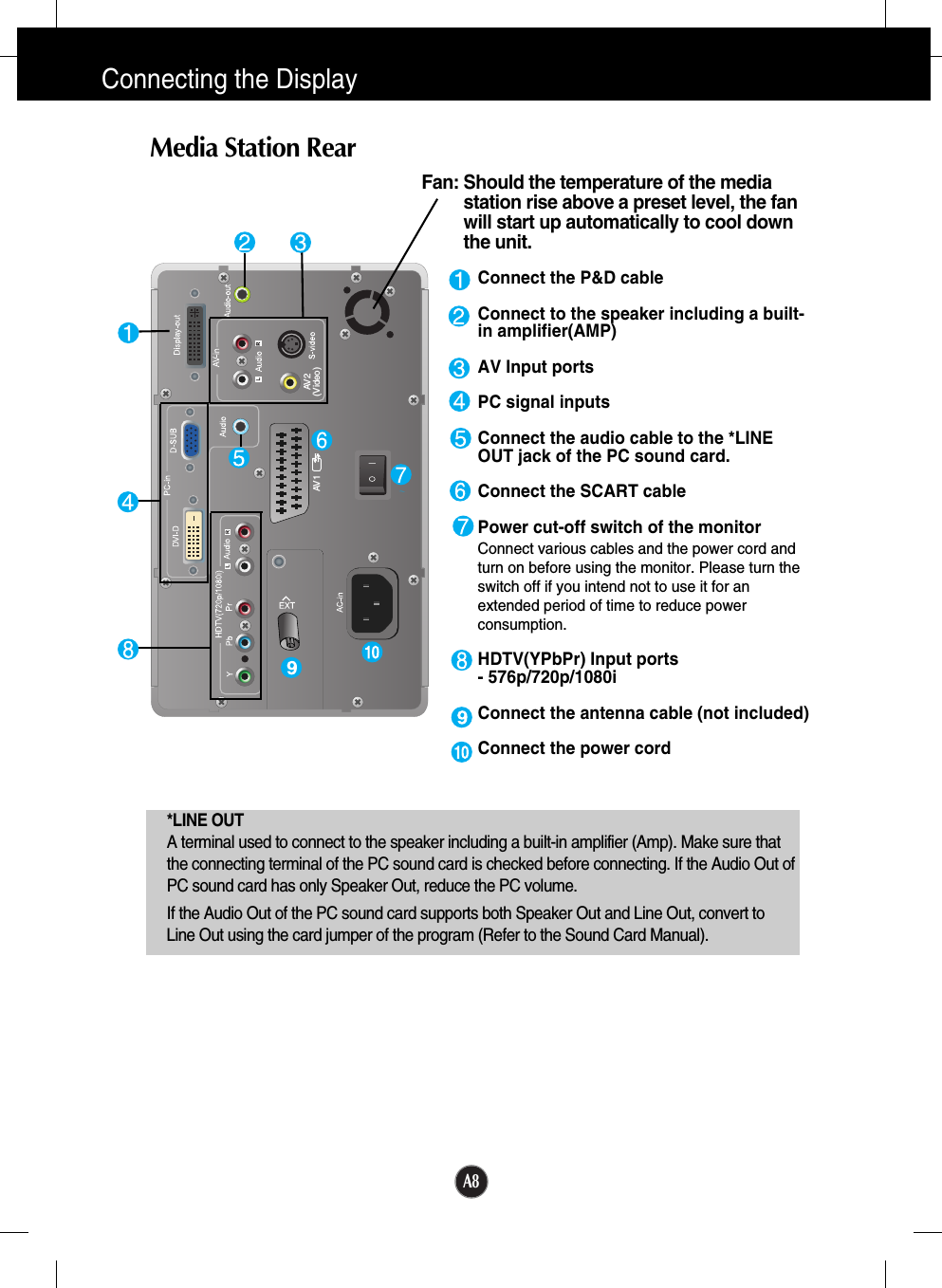
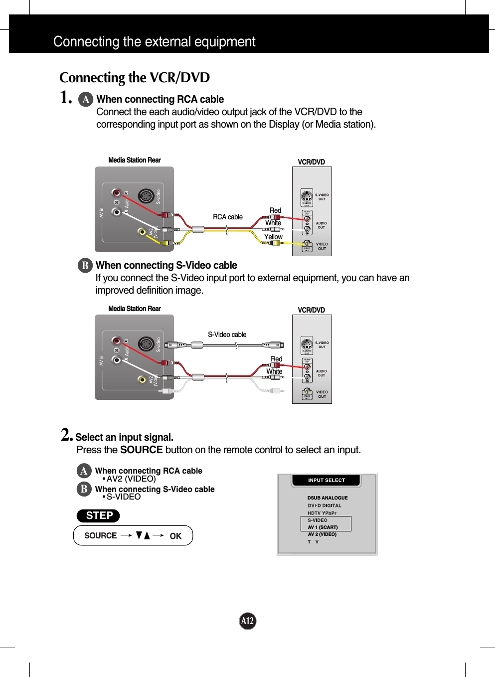
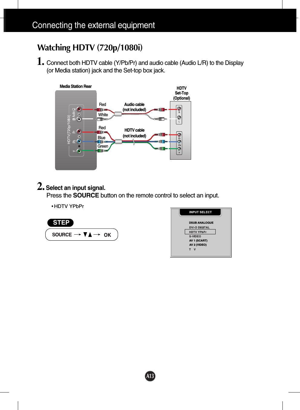
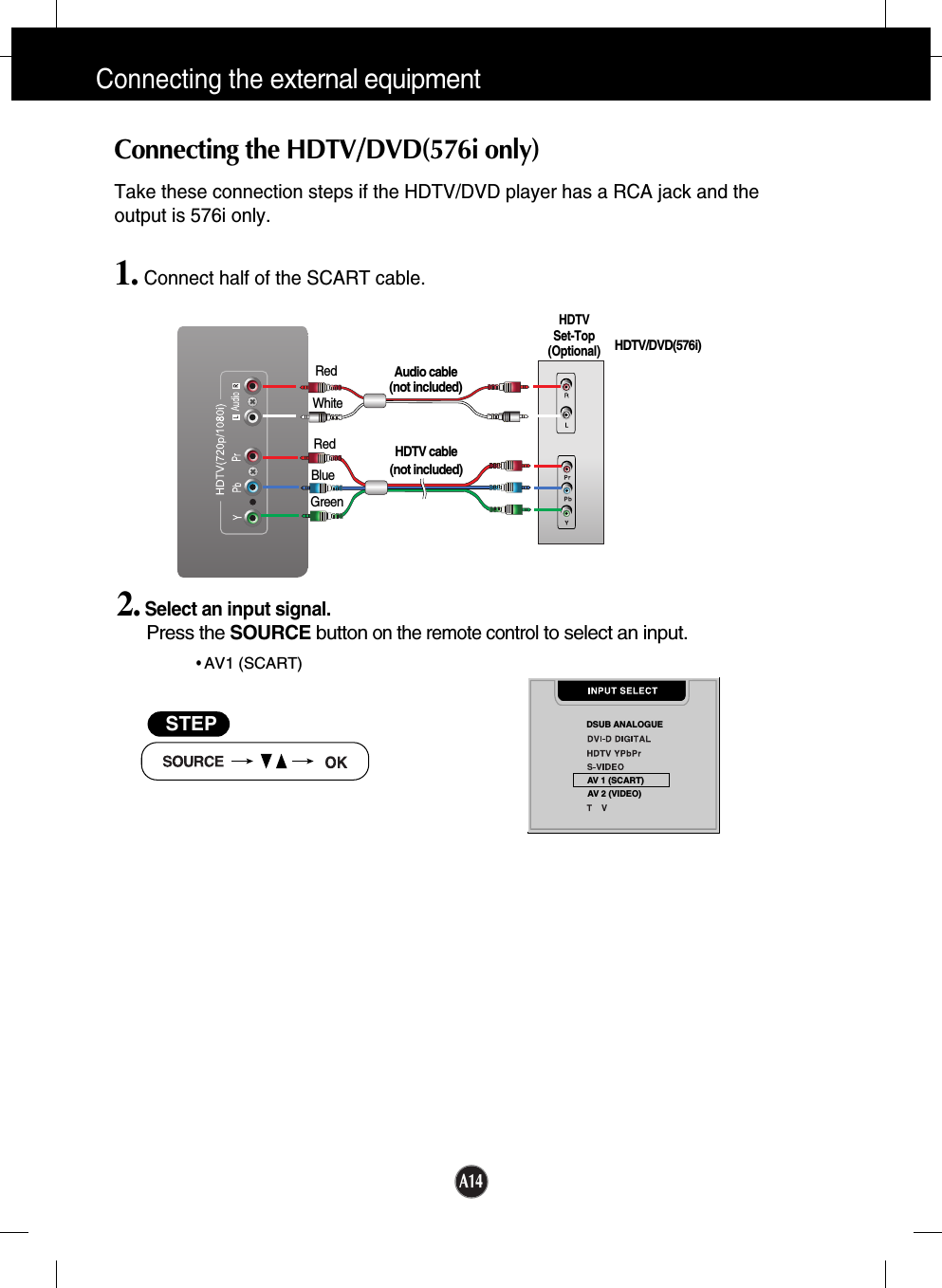
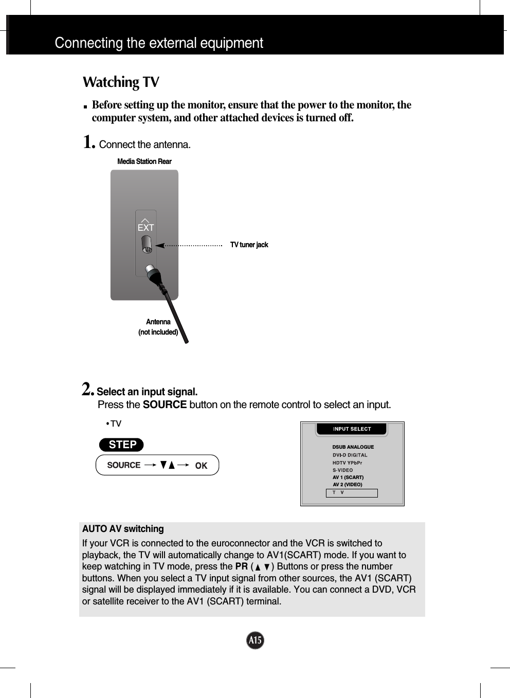
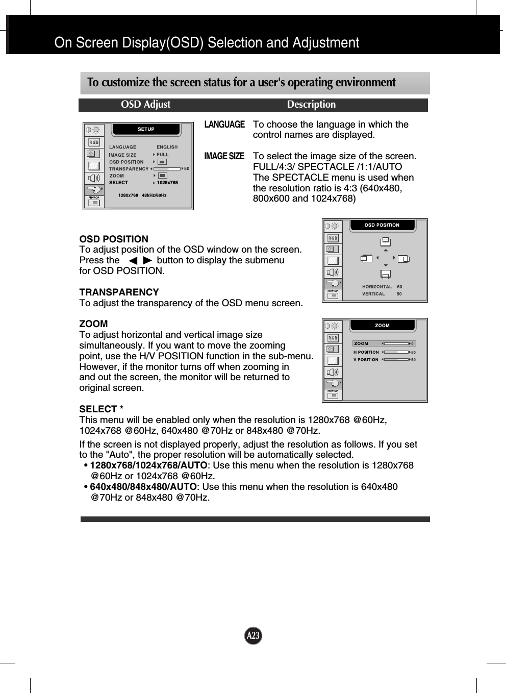
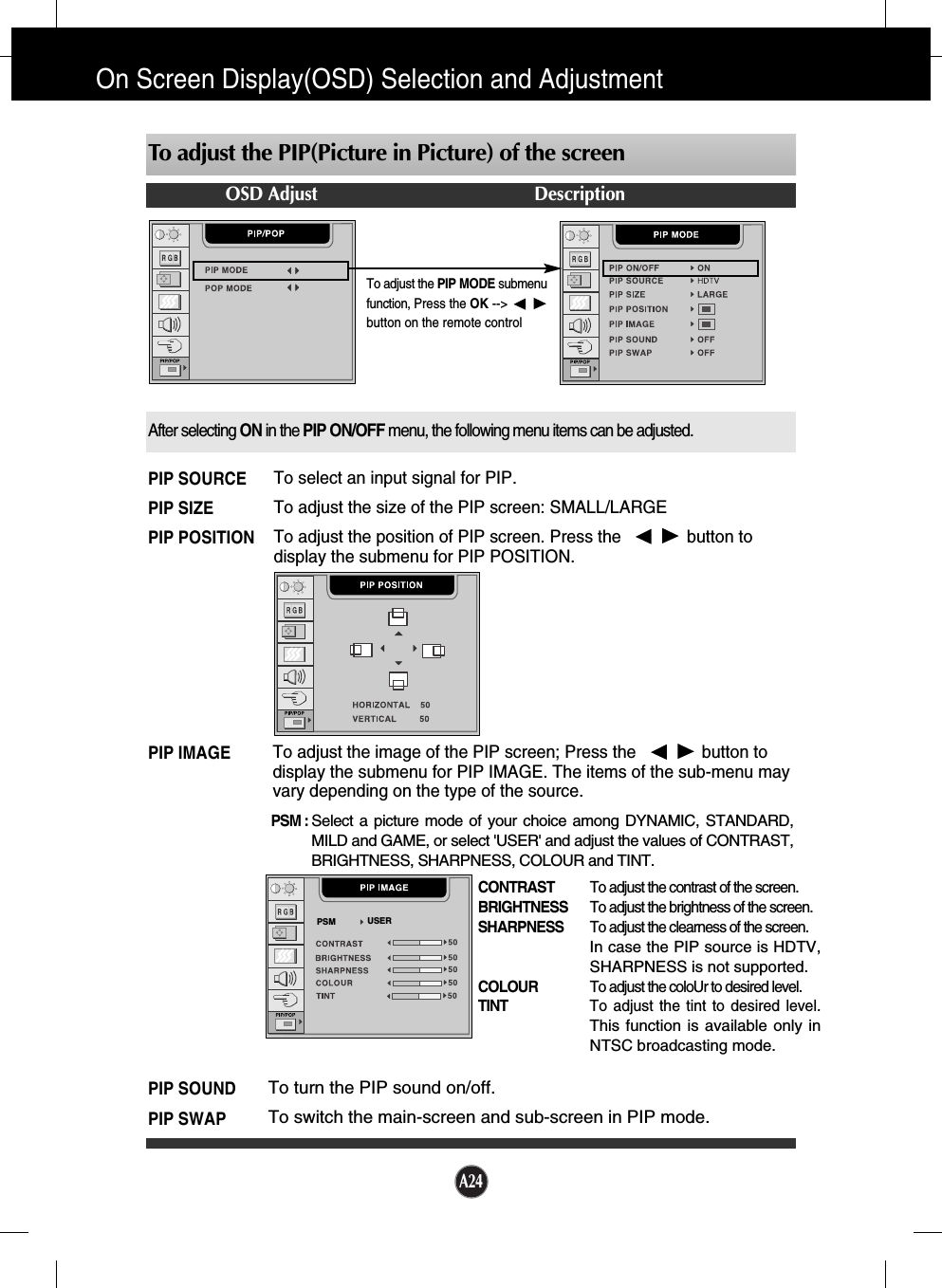
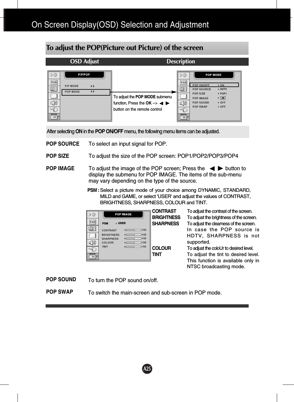
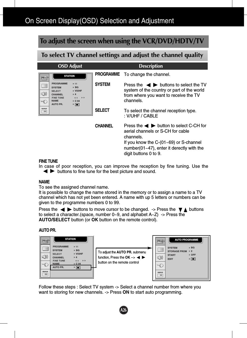
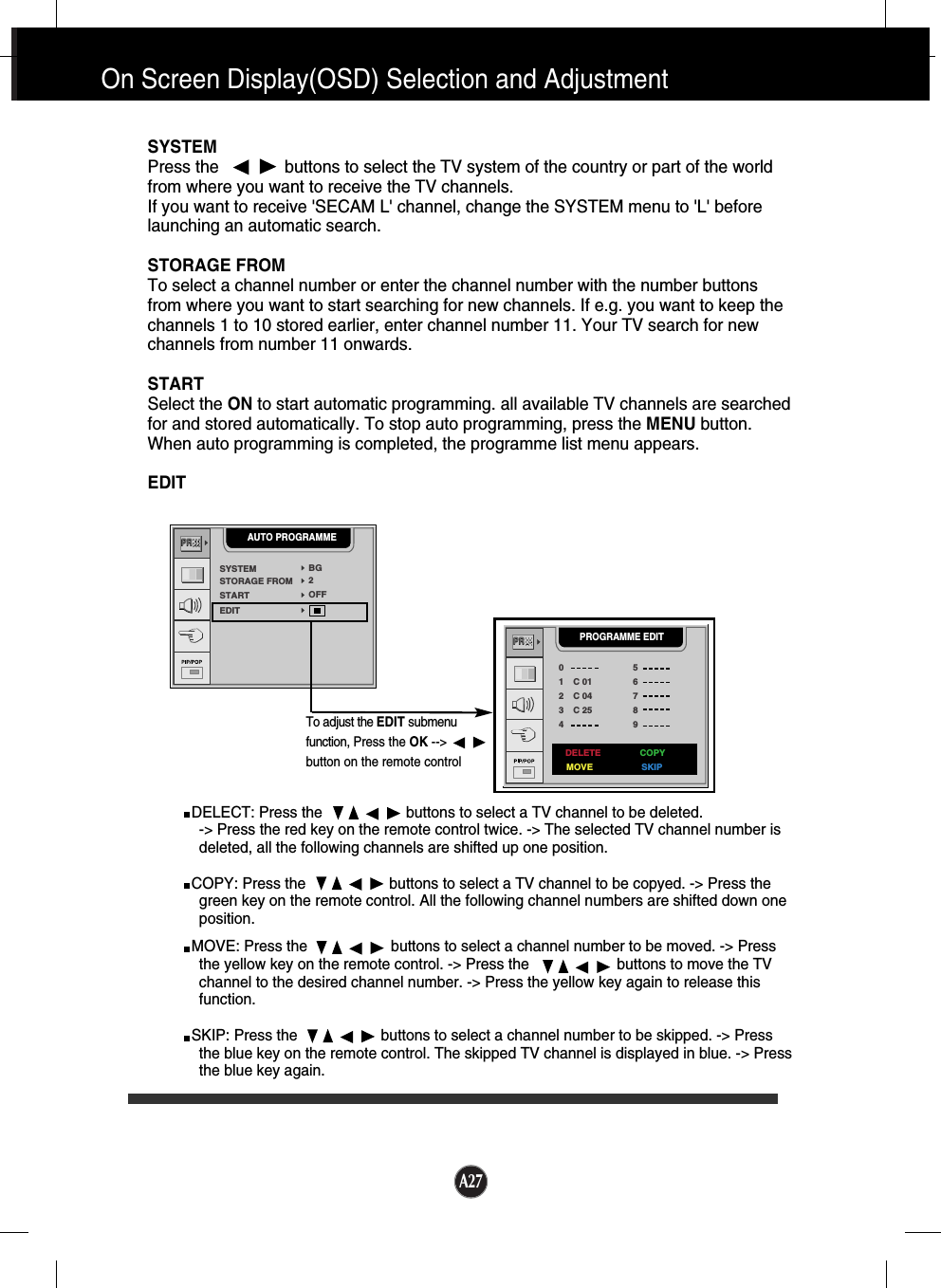
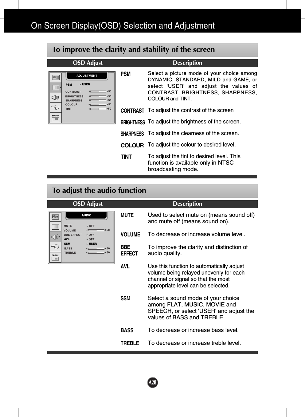
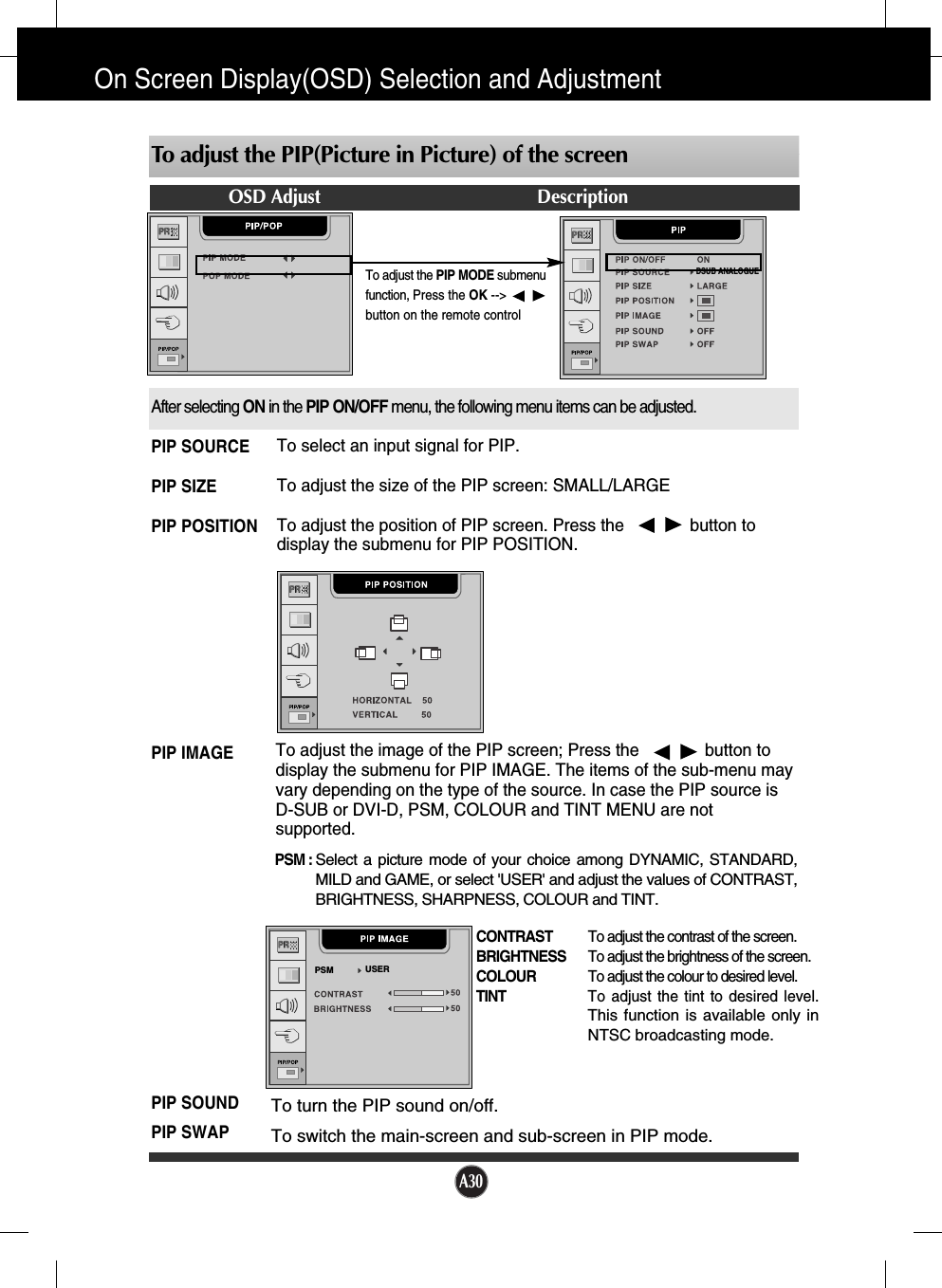
![A29FULLYou can enjoy the picture (format of 4:3) or general TV in 16:9 mode.4:3This picture format is 4 to 3 of general TVSPECTACLEThis function provides different areas of the screen with a varied ratio, so that the ratio at thecentral area is close to 4:3 and near the edges it exceeds 16:9. Since most peopleconcentrate their focus upon the central area of the screen, they do not clearly recognize anonlinear expansion of the image near the edges of the display. Therefore a 4:3 image can fitinto the wide screen naturally. ZOOM 1/ZOOM 2Zoom 1 and 2 are functions, which keeps the input ratio constant at 16:9 while zooming in;these functions, unlike conventional zoom in function, minimize the image distortion usuallyseen in the zooming process. Input source can be controlled only in AV1 (SCART), AV2 (VIDEO), TV, S-VIDEO states.AUTOWhen your set receives a wide screen signal, it will automatically change to the picture formatto be sent.On Screen Display(OSD) Selection and Adjustment To customize the screen status for a user's operating environmentOSD Adjust DescriptionLANGUAGEIMAGE SIZE[example]Image Size 4:316:9ScreenZOOM1FULL ZOOM2Input SourceTo choose the language in which the controlnames are displayed.To select the image size of the screen.FULL/4:3/ SPECTACLE /ZOOM1/ZOOM2/AUTO.SPECTACLE, ZOOM1, ZOOM2 and AUTOfunctions are useful for TV or motionpictures, but not suitable for PCenvironments such as computer graphics orword processing.OSD POSITIONTo adjust position of the OSD window on the screen. Press the button to display the submenufor OSD POSITION.TRANSPARENCYTo adjust the transparency of the OSD menu screen.COLOURTo select the screen colour. • 9300K: Slightly bluish white. • 6500K: Slightly reddish white.](https://usermanual.wiki/LG-Electronics-USA/L23LW/User-Guide-411530-Page-34.png)