LG Electronics USA L23LW 23-inch LCD TV Monitor User Manual User s Manual I
LG Electronics USA 23-inch LCD TV Monitor User s Manual I
Users Manual
Make sure to read the Important Precautions before using the product.
Keep the User's Guide(CD) in an accessible place for furture reference.
See the label attached on the back cover and quote this information to your
dealer when you require service.
L23LW
User’s Guide
1
FCC Compliance Statement
This equipment has been tested and found to comply within
the limits of a Class B digital device pursuant to Part 15 of
the FCC Rules. These limits are designed to provide
reasonable protection against harmful interference in a
residential installation.
This equipment generates, uses, and can radiate radio
frequency energy and if not installed and used in
accordance with the instructions, may cause harmful
interference to radio communications. However, there is no
guarantee that interference will not occur in a particular
installation.
If this equipment does cause harmful interference to radio
or television reception (which can be determined by turning
the equipment on and off), the user is encouraged to try to
correct the interference by using one or more of the
following measures:
Reorient or relocate the receiving antenna.
Increase the separation between the equipment and the
receiver.
Connect the equipment into an outlet on a circuit
different from that to which the receiver is connected.
Consult the dealer or an experienced radio/TV
technician for help.
Caution: Changes or modifications not expressly approved
by the party responsible for compliance could void the
user's (or your) authority to operate the equipment. Only
peripherals (digital input/output devices, terminals, printers,
etc.) certified to comply with the Class B limits may be
attached to this monitor. Operation with non-certified
peripherals is likely to result in interference to radio and TV
reception.
Only shielded signal cables may be used with this System.
Canadian DOC Notice
This Class B digital apparatus meets all requirements of the
Canadian Interference-Causing Equipment Regulations.
Cet appareil numérique de la classe B respecte toutes les
exigences du Règlement sur le matériel brouilleur du
Canada.
CE Conformity Notice (for Europe)
Products with the “CE” Marking comply with the EMC
Directive(89/336/EEC) and LOW VOLTAGE Directive
(73/23/EEC) issued by the Commission of the European
Community.
Compiance with these directives implies conformity to the
following European Norms :
• EN 55022:1998 ; Radio Frequency Interference
• EN 55024:1998 ; Electromagnetic Immunity
• EN 61000-3-2 ; Power Line Harmonics
• EN 61000-3-3 ; Voltage Fluctuations
• EN 60950 ; Product Safety
Low Radiation Compliance (MPR II)
This monitor meets one of the strictest guidelines available
today for low radiation emissions, offering the user extra
shielding and an antistatic screen coating. These
guidelines, set forth by a government agency in Sweden,
limit the amount of emission allowed in the Extremely Low
Frequency (ELF) and Very Low Frequency (VLF)
electromagnetic range.
TCO95
Congratulations!
You have just purchased a TCO’95 approved and labelled
product! Your choice has provided you with a product
developed for professional use. Your purchase has also
contributed to reducing the burden on the environment and
to the further development of environmentally-adapted
electronic products.
Why do we have environmentally labelled computers?
In many countries, environmental labelling has become an
established method for encouraging the adaptation of
goods and services to the environment. The main problem
as far as computers and other electronic equipment are
concerned is that environmentally harmful substances are
used both in the products and during their manufacture.
Since it has not been possible so far for the majority of
electronic equipment to be recycled in a satisfactory way,
most of these potentially damaging substances sooner or
later enter Nature.
There are also other characteristics of a computer, such as
energy consumption levels, that are important from both the
working and natural environment viewpoints. Since all
types of conventional electricity generation have a negative
effect on the environment (acidic- and climatic-influencing
emissions, radioactive waste, etc.), it is vital to conserve
energy. Electronic equipment in offices consumes as
enormous amount of energy, since it is often routinely left
running continuously.
What does the environmenal labelling involve?
This product meets the requirements for the TCO’95
Regulatory Information
NOTICE
The regulations are applied only to the products with the
ID LABEL indicating specific requirements.
NOTICE
The regulations are applied only to the products with the
ID LABEL indicating specific requirements.
NOTICE
The regulations are applied only to the products with the
ID LABEL indicating specific requirements.
2
Regulatory Information cont.
NUTEK
Naturskydds
föreningen
Närings- och teknikutvecklingsverket
SEMKO
scheme, which provides for international environmental
labelling of personal computers. The labelling scheme was
developed as a joint effort by the TCO (The Swedish
Confederation of Professional Employees),
Naturckyddsföreningen (The Swedish Society for Nature
Conservation), and NUTEK (The National Board for
Industrial and Technical Development in Sweden), and
SEMKO AB (an international certification agency).
The requirements cover a wide range of issues:
environment, ergonomics, usability, emission of electrical
and magnetic fields, energy consumption and electrical and
fire safety.
The environmental demands concern, among other things,
restriction on the presence and use of heavy metals,
brominated and chlorinated flame retardants, CFCs
(freons), and chlorinated solvents. The product must be
prepared for recycling, and the manufacturer is obliged to
have an environmental plan, which must be adhered to in
each country where the company implements its
operational policy.
The energy requirements include a demand that the
computer and/or display, after a certain period of inactivity,
shall reduce its power consumption to a lower level, in one
or more stages. The length of time to reactivate the
computer shall be reasonable for the user.
Labelled products must meet strict environmental
demands, for example, in respect of the reduction of electric
and magnetic fields, along with physical and visual
ergonomics and good usability.
The following is a brief summary of the environmental
requirements met by this product. The complete
environmental criteria document may be ordered from:
TCO Development Unit
Linnegatan 14, S-11494 Stockholm, Sweden
FAX +46-8 782 92 07
E-mail (Internet): development@tco.se
Current information regarding TCO’95 approved and
labelled products may also be obtained on the Internet
using the address: http://www.tco-info.com/
TCO’95 is a co-operative project between:
Environmental requirements
Brominated flame retardants are present in printed circuit
boards, cabling, casings, and housings, and are added to
delay the spread of fire. Up to 30% of the plastic in a
computer casing can consist of flame-retardant substances.
These are related to another group of environmental toxins,
PCBs, and are suspected of giving rise to similar harm,
including reproductive damage in fish-eating birds and
mammals. Flame retardants have been found in human
blood, and researchers fear that they can disturb fetus
development.
Bio-accumulative1TCO’95 demands require that plastic
components weighing more than 25 grams must not
contain flame retardants with organically bound chlorine or
bromine.
Lead can be found in picture tubes, display screens, solder,
and capacitors. Lead damages the nervous system and in
higher doses causes lead poisoning. The relevant bio-
accumulative TCO’95 requirement permits the inclusion of
lead, as no replacement has yet been developed.
Cadmium is present in rechargeable batteries and in the
color-generating layers of certain computer displays.
Cadmium damages the nervous system and is toxic in high
doses. The relevant bio-accumulative TCO’95 requirement
states that batteries may not contain more than 25 ppm
(parts per million) of cadmium. The color-generating layers
of display screens must not contain any cadmium.
Mercury is sometimes found in batteries, relays and
switches. Mercury damages the nervous system and is
toxic in high doses. The relevant bio-accumulative TCO’95
requirement states that batteries may not contain more than
25 ppm of mercury and that no mercury is present in any of
the electrical or electronic components concerned with the
display unit.
CFCs (freons) are sometimes used for washing printed
circuit boards and in the manufacture of expanded foam for
packaging. CFCs break down ozone and thereby damage
the ozone layer in the atmosphere, causing increased
reception on Earth of ultra-violet light with consequent
increased risks of skin cancer (malignant melanoma). The
relevant TCO’95 requirement: Neither CFCs nor HCFCs
may be used during the manufacture of the product or its
packaging.
1Bio-accumulative means that the substance accumulates
within living organisms.
Shipping Package
The packaging material can be recycled, or you can save it
to return the monitor to a service center for repair or
disposal.
CFC Compounds in Distribution Packaging
Cushioning material used for shipping finished monitors are
not manufactured with nor do they contain any CFC
compounds.
Design for Disassembly/Recycling
These monitors have been designed for easy end-of-life
disassembly and recycling. Fasteners are generally of the
same type for efficient disassembly. Components made of
different materials can be easily separated and plastics
have been identified using intermational symbols to aid in
recycling.
Monitor Disposal
WARNING
If you need to dispose of a monitor, ask a qualified service
representative for the proper procedure. Improper disposal
could result in personal injury from implosion.

3
TCO99
Congratulations!
You have just purchased a TCO’99 approved and
labelled product! Your choice has provided you with
a product developed for professional use. Your
purchase has also contributed to reducing the
burden on the environment and also to the further
development of environmentally adapted electronics
products.
Why do we have environmentally labelled
computers?
In many countries, environmental labelling has
become an established method for encouraging the
adaptation of goods and services to the environment.
The main problem, as far as computers and other
electronics equipment are concerned, is that
environmentally harmful substances are used both in
the products and during their manufacture. Since it is
not so far possible to satisfactorily recycle the
majority of electronics equipment, most of these
potentially damaging substances sooner or later
enter nature.
There are also other characteristics of a computer,
such as energy consumption levels, that are
important from the viewpoints of both the work
(internal) and natural (external) environments. Since
all methods of electricity generation have a negative
effect on the environment (e.g. acidic and climate-
influencing emissions, radioactive waste), it is vital to
save energy. Electronics equipment in offices is
often left running continuously and thereby
consumes a lot of energy.
What does labelling involve?
This product meets the requirements for the TCO’99
scheme which provides for international and
environmental labelling of personal computers. The
labelling scheme was developed as a joint effort by
the TCO (The Swedish Confederation of
Professional Employees), Svenska
Naturskyddsforeningen (The Swedish Society for
Nature Conservation) and Statens Energimyndighet
(The Swedish National Energy Administration).
Approval requirements cover a wide range of issues:
environment, ergonomics, usability, emission of
electric and magnetic fields, energy consumption
and electrical and fire safety.
The environmental demands impose restrictions on
the presence and use of heavy metals, brominated
and chlorinated flame retardants, CFCs (freons) and
chlorinated solvents, among other things. The
product must be prepared for recycling and the
manufacturer is obliged to have an environmental
policy which must be adhered to in each country
where the company implements its operational
policy.
The energy requirements include a demand that the
computer and/or display, after a certain period of
inactivity, shall reduce its power consumption to a
lower level in one or more stages. The length of time
to reactivate the computer shall be reasonable for
the user.
Labelled products must meet strict environmental
demands, for example, in respect of the reduction of
electric and magnetic fields, physical and visual
ergonomics and good usability.
Below you will find a brief summary of the
environmental requirements met by this product. The
complete environmental criteria document may be
ordered from:
TCO Development
SE-114 94 Stockholm, Sweden
Fax: +46 8 782 92 07
Email (Internet): development@tco.se
Current information regarding TCO’99 approved and
labelled products may also be obtained via the Internet,
using the address: http://www.tco-info.com/
Environmental requirements
Flame retardants
Flame retardants are present in printed circuit
boards, cables, wires, casings and housings. Their
purpose is to prevent, or at least to delay the spread
of fire. Up to 30% of the plastic in a computer casing
can consist of flame retardant substances. Most
flame retardants contain bromine or chloride, and
those flame retardants are chemically related to
another group of environmental toxins, PCBs. Both
the flame retardants containing bromine or chloride
and the PCBs are suspected of giving rise to severe
health effects, including reproductive damage in
fish-eating birds and mammals, due to the bio-
accumulative* processes. Flame retardants have
been found in human blood and researchers fear
that disturbances in foetus development may occur.
The relevant TCO’99 demand requires that plastic
components weighing more than 25 grams must not
contain flame retardants with organically bound
bromine or chlorine. Flame retardants are allowed in
the printed circuit boards since no substitutes are
available.
Cadmium**
Cadmium is present in rechargeable batteries and in
the colour-generating layers of certain computer
displays. Cadmium damages the nervous system
and is toxic in high doses. The relevant TCO’99
requirement states that batteries, the colour-
generating layers of display screens and the
electrical or electronics components must not contain
any cadmium.
Regulatory Information cont.
4
Regulatory Information cont.
Mercury**
Mercury is sometimes found in batteries, relays and
switches. It damages the nervous system and is
toxic in high doses. The relevant TCO’99
requirement states that batteries may not contain
any mercury. It also demands that mercury is not
present in any of the electrical or electronics
components associated with the labelled unit.
CFCs (freons)
The relevant TCO’99 requirement states that neither
CFCs nor HCFCs may be used during the
manufacture and assembly of the product. CFCs
(freons) are sometimes used for washing printed
circuit boards. CFCs break down ozone and thereby
damage the ozone layer in the stratosphere, causing
increased reception on earth of ultraviolet light with
e.g. increased risks of skin cancer (malignant
melanoma) as a consequence.
Lead**
Lead can be found in picture tubes, display screens,
solders and capacitors. Lead damages the nervous
system and in higher doses, causes lead poisoning.
The relevant TCO’99 requirement permits the
inclusion of lead since no replacement has yet been
developed.
* Bio-accumulative is defined as substances which
accumulate within living organisms
** Lead, Cadmium and Mercury are heavy metals which are
Bio-accumulative.
EPA (U.S.A only)
ENERGYSATR is a set of power-saving guidelines
issued by the U.S. Environmental Protection
Agency(EPA).
NOM MARK (Mexico only)
GOST MARK
EPA POLLUTION PREVENTER
As an ENERGY STAR Partner LG
Electronics U.S.A.,Inc. has
determined that this product meets the
ENERGY STAR guidelines for
energy efficiency.
BZ03
Internet Address:http://www.lg.ru
»ÌÙÓχˆËÓÌ̇ˇ ÒÎÛÊ·‡ LG
Electronics (095)742-77-77

A1
This unit has been engineered and manufactured to ensure your personal
safety, however improper use may result in potential shock or fire hazards.
In order to allow the proper operation of all safeguards incorporated in this
display, observe the following basic rules for its installation, use, and
servicing.
On Safety
Use only the power cord supplied with the unit. In case you use another power
cord, make sure that it is certified by the applicable national standards if not being
provided by the supplier. If the power cable is faulty in any way, please contact the
manufacturer or the nearest authorized repair service provider for a replacement.
The power supply cord is used as the main disconnection device. Ensure that the
socket-outlet is easily accessible after installation.
Operate the display only from a power source indicated in the specifications of this
manual or listed on the display. If you are not sure what type of power supply you
have in your home, consult with your dealer.
Overloaded AC outlets and extension cords are dangerous. So are frayed power
cords and broken plugs. They may result in a shock or fire hazard. Call your
service technician for replacement.
Do not Open the Display.
There are no user serviceable components inside.
There are Dangerous High Voltages inside, even when the power is OFF.
Contact your dealer if the display is not operating properly.
To Avoid Personal Injury :
Do not place the display on a sloping shelf unless properly secured.
Use only a stand recommended by the manufacturer.
To Prevent Fire or Hazards:
Always turn the display OFF if you leave the room for more than a short period
of time. Never leave the display ON when leaving the house.
Keep children from dropping or pushing objects into the display's cabinet
openings. Some internal parts carry hazardous voltages.
Do not add accessories that have not been designed for this display.
During a lightning storm or when the display is to be left unattended for an
extended period of time, unplug it from the wall outlet.
Do not place objects on top of the media station or cover it. Obstructing
ventilation holes may damage your media station or overheat the machine
causing fire.
Important Precautions

A2
Important Precautions
On Installation
Do not allow anything to rest upon or roll over the power cord, and do not place the
display where the power cord is subject to damage.
Do not use this display near water such as near a bathtub, washbowl, kitchen sink,
laundry tub, in a wet basement, or near a swimming pool.
Displays are provided with ventilation openings in the cabinet to allow the release
of heat generated during operation. If these openings are blocked, built-up heat
can cause failures which may result in a fire hazard. Therefore, NEVER:
Block the bottom ventilation slots by placing the display on a bed, sofa, rug, etc.
Place the display in a built-in enclosure unless proper ventilation is provided.
Cover the openings with cloth or other material.
Place the display near or over a radiator or heat source.
Do not rub or strike the Active Matrix LCD with anything hard as this may scratch,
mar, or damage the Active Matrix LCD permanently.
Do not press the LCD screen with your finger for a long time as this may cause
some afterimages.
Some dot defects may appear as Red, Green or Blue spots on the screen.
However, this will have no impact or effect on the display performance.
If possible, use the recommended resolution to obtain the best image quality for
your LCD display. If used under any mode except the recommended resolution,
some scaled or processed images may appear on the screen. However, this is
characteristic of the fixed-resolution LCD panel.
On Cleaning
Unplug the display before cleaning the face of the display screen.
Use a slightly damp (not wet) cloth. Do not use an aerosol directly on the display
screen because over-spraying may cause electrical shock.
On Repacking
Do not throw away the carton and packing materials. They make an ideal
container in which to transport the unit. When shipping the unit to another
location, repack it in its original material.
Unpacking Your Display
A3
Speakers
I/II
TV/AV
*
/SSM
AUTO
TEXT SLEEP MODE
UPDATE LIST TIME
SIZE Q.VIEW MIX
HOLD
INDEX
APC/PSM REVEAL
SWAP
PR
VOLVOL
PR
OK
M
X
?
i
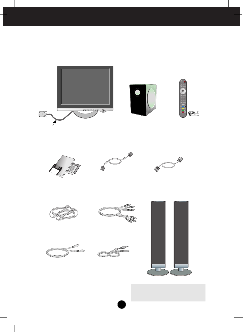
Please make sure the following items are included with your monitor. If any
items are missing, contact your dealer.
Media Station Remote control /
Batteries (AAA x 2)
user's Manual/
Cards
15-pin D-Sub Signal Cable DVI-D Signal Cable
Power Cord RCA Cable
S-Video Cable Audio Cable (PC)
Display
P&D cable
Please see the Speaker User Manual
(included in the speaker box) to reference
the speaker accessory list.
A4
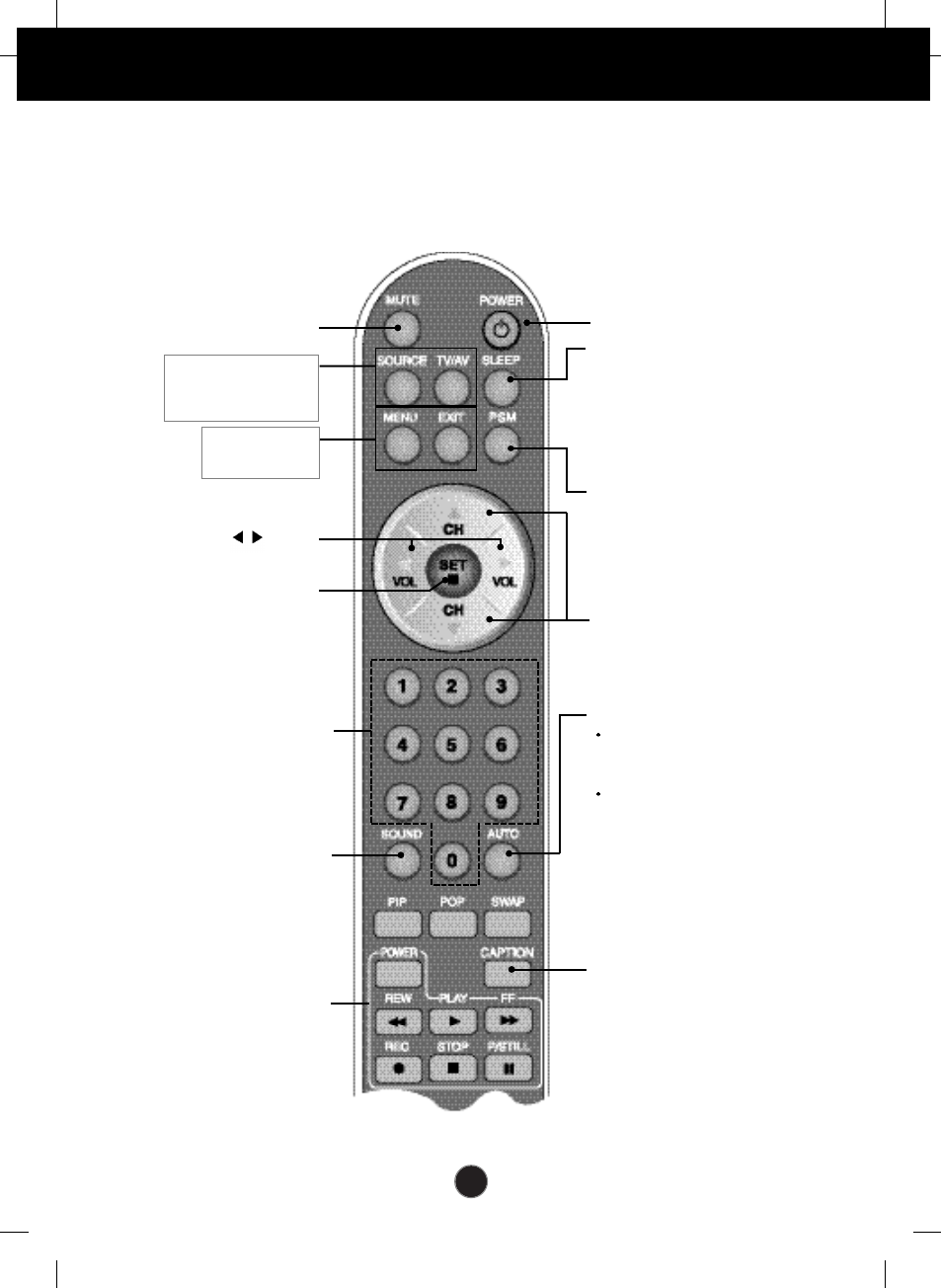
Using the Remote Control
Remote Control
For detailed instructions of each button on the remote control, refer to the
appropriate pages of this manual.
Power On/Off Button
Channel Up/Down Button
•
Input Select Button
•
TV/AV Button
(See next page)
Sleep Button
When watching AV/DVD/HDTV/TV
-
The monitor will be automatically
turned off after a certain period of
time.
Press this button repetitively to
select an appropriate time duration
PSM Button
When watching
AV/DVD/HDTV/TV
- Automatically adjusts the image.
Press this button repetitively to
set the intended screen. (See
A27)
CAPTION Button
(See A33)
•
Menu Button
•
Exit Button
Auto Channel Button
TV: Automatic TV channel
setup(Applicable to the model
equipped with the TV tuner)
PC: Automatic adjustment
function(Operational for
the analog signal only)
Channel Number Select
Button
Operational at the TV mode only
Check Button
Sound Mode Select
Select the sound mode
: MONO/STEREO/SAP
Video Operation Button
Applicable for LG products only
Volume Button
Mute button
A5
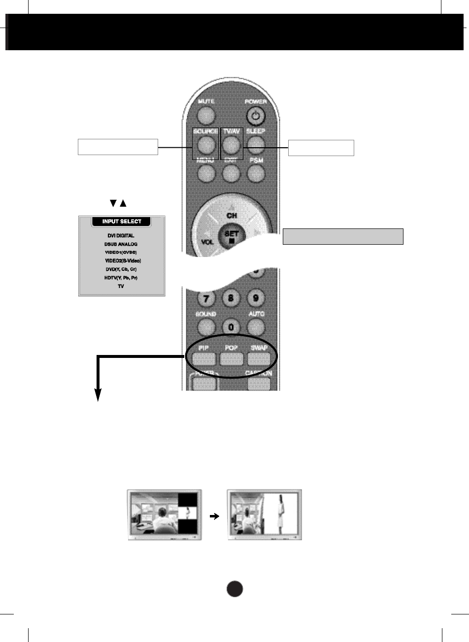
Using the Remote Control
Remote Control
1. PIP (Picture in Picture) Button
The sub-screen moves to the next mode whenever you press this button.
: SMALL -> LARGE -> OFF
2. POP (Picture out Picture) Button
The sub-screen moves to the next mode whenever you press this button.
: POP ON -> PBP(FULL) -> PBP(4:3) -> OFF
If you press the button once,
the following Input Signal
Window will appear. Select
the signal type you want
using the button.
This button will be enabled only
when you selected the TV/AV
signal. The signal type will be
changed with the following
order. Set the signal type you
want.
POP ON PBP (FULL)
•
Input Select Button
•
TV/AV Button
TV > VIDEO >VEDIO2 > DVD > HDTV
A6
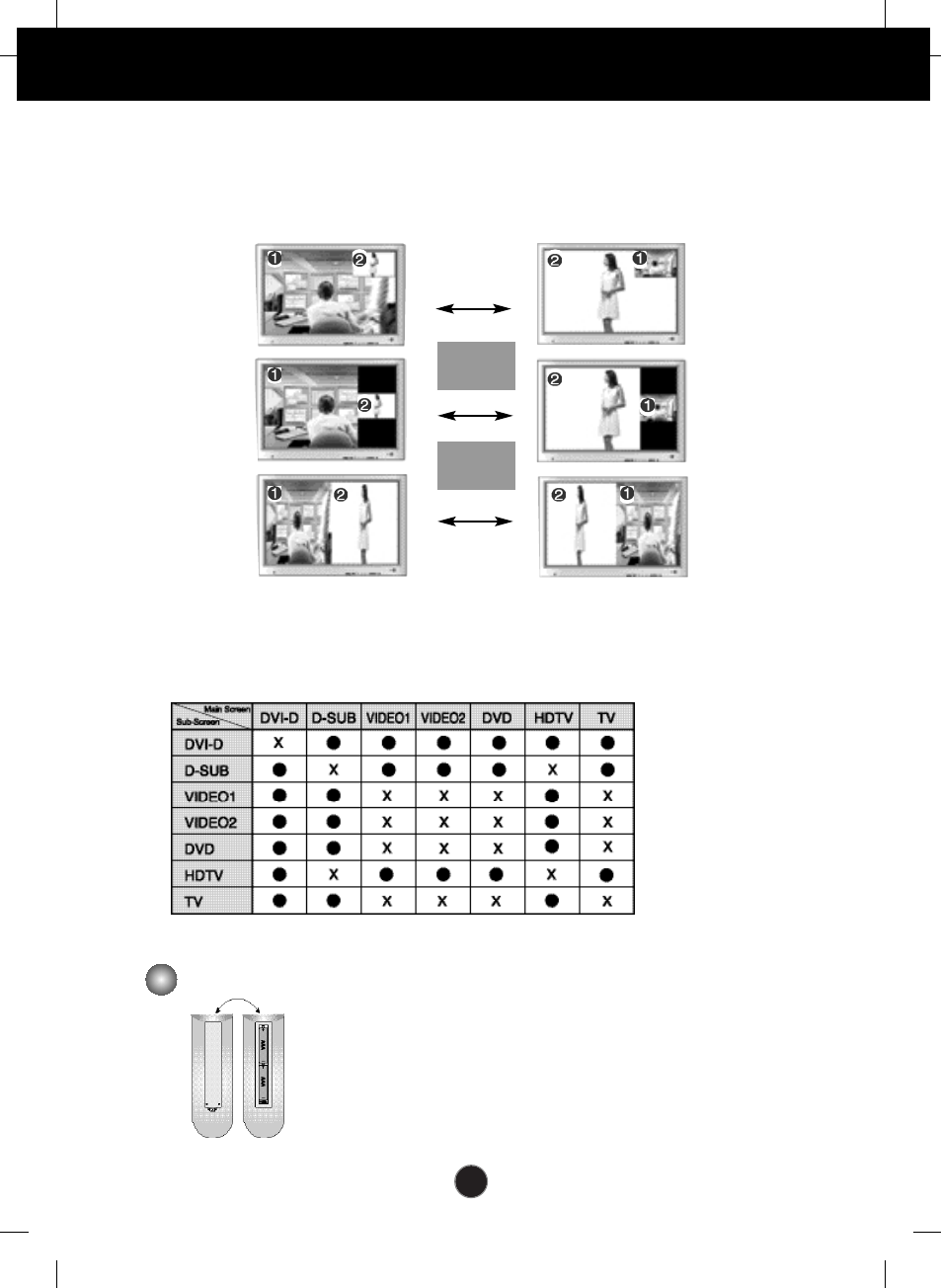
<Table of PIP/POP/PBP Function Support>
SWAP
SWAP
When 'Input Signal 1' comes on in the main screen, only 'Input Signal 2' can be displayed on the sub-screen. On
the contrary, if the main screen displays 'Input Signal 2', the sub-screen can display 'Input Signal 1' only. You can
swap 'Input Signal 1' and 'Input Signal 2' using the SWAP button.
1. Take out the battery cap.
2. Insert the battery with correct polarity (+/-).
3. Close the battery cap.
• You can use a remote controller 7 meter distance and 30 degree (left/right)
within the receiving unit scope.
• Dispose of used batteries in the recycle bin to prevent environmental pollution.
Inserting batteries into remote controller.
3. Swap Button
You can swap the main screen and the sub-screen when the PIP/POP/PBP function is used..
PIP
POP
PBP
A7
Using the Remote Control
This section shows you how to use the remote control.
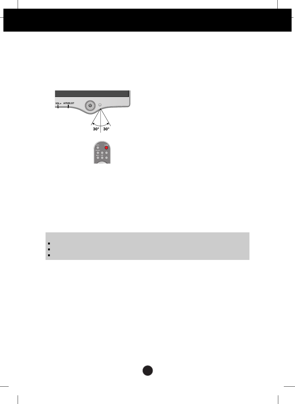
Operating with the Remote Control
Point the remote control at the remote sensor and press the buttons.
Distance : About 23 ft (7 m) from the
front of the remote sensor.
Angle : About 30° in each direction
of the front of the remote
sensor.
Do not expose the sensor of remote control in the monitor to a strong light source
such as direct sunlight or illumination. If so, may not be able to operate the monitor
with the remote control.
I/II
TV/AV
*
/SSM
Note
Do not drop the remote control or handle it roughly.
Do not leave the remote control in extremely hot or humid conditions.
Do not expose the remote control to water or anything wet.
Within about 23ft (about 7m)
A8
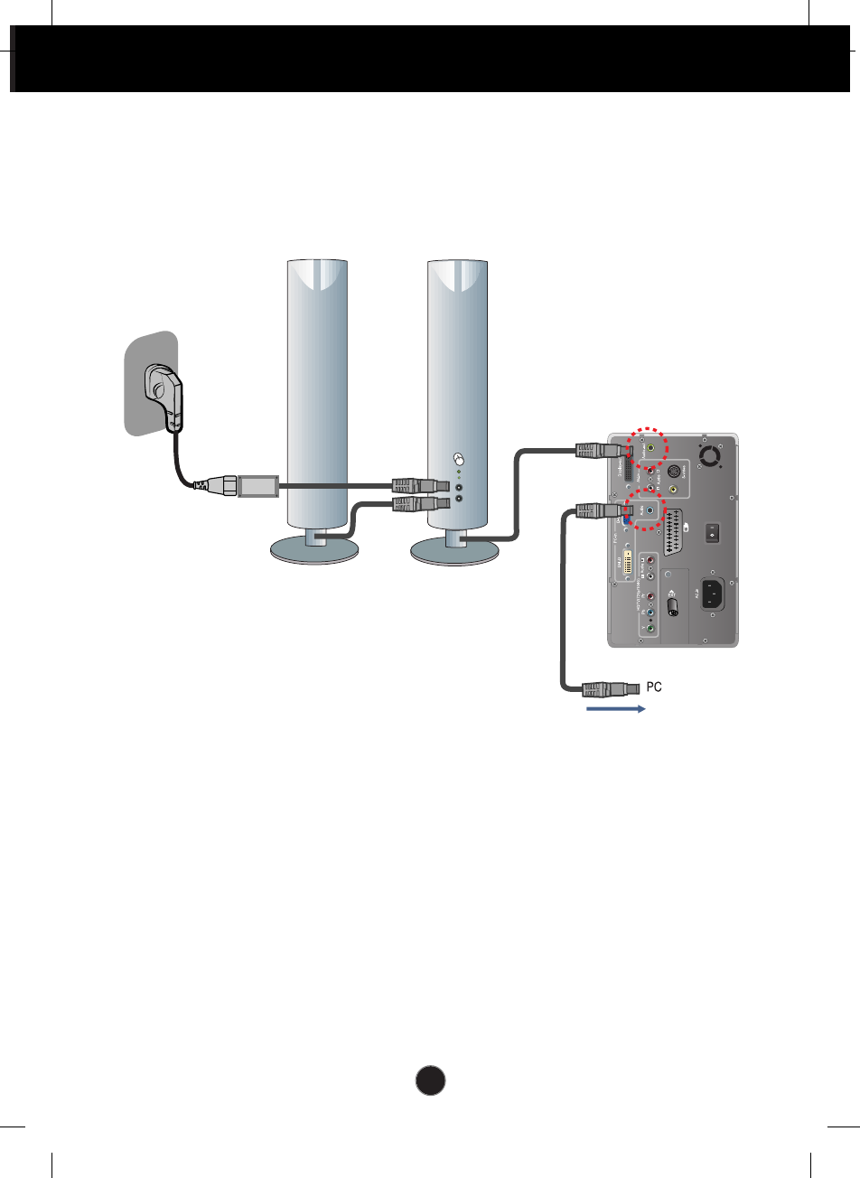
Connecting the Display
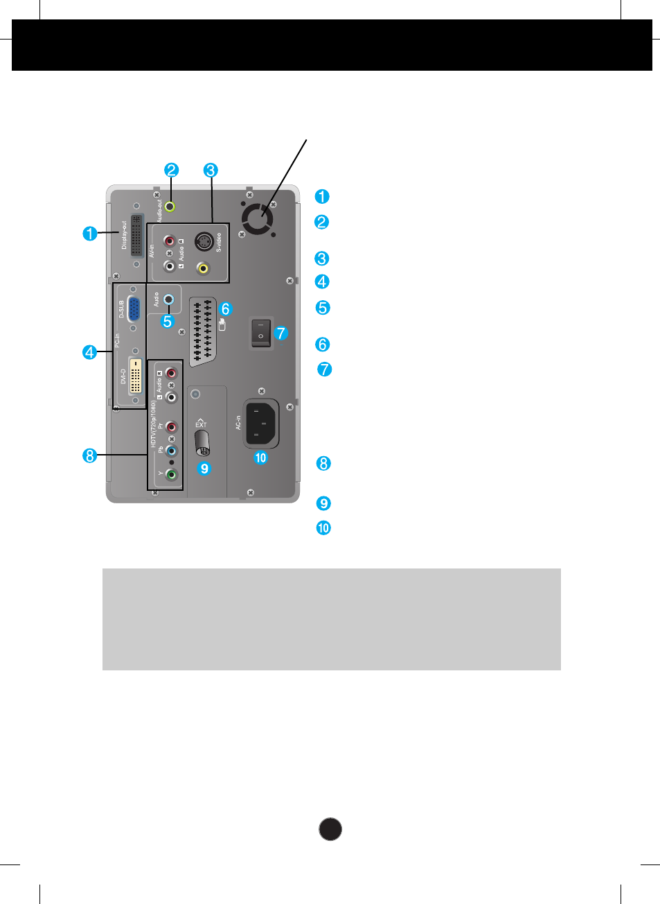
Media Station Rear
AV1
AV2
(Video)
Connect the P&D cable
Connect to the speaker including a built-
in amplifier(AMP)
AV Input ports
PC signal inputs
Connect the audio cable to the *LINE
OUT jack of the PC sound card.
Connect the SCART cable
Power cut-off switch of the monitor
Connect various cables and the power cord and
turn on before using the monitor. Please turn the
switch off if you intend not to use it for an
extended period of time to reduce power
consumption.
HDTV(YPbPr) Input ports
- 576p/720p/1080i
Connect the antenna cable (not included)
Connect the power cord
*LINE OUT
A terminal used to connect to the speaker including a built-in amplifier (Amp). Make sure that
the connecting terminal of the PC sound card is checked before connecting. If the Audio Out of
PC sound card has only Speaker Out, reduce the PC volume.
If the Audio Out of the PC sound card supports both Speaker Out and Line Out, convert to
Line Out using the card jumper of the program (Refer to the Sound Card Manual).
Fan: Should the temperature of the media
station rise above a preset level, the fan
will start up automatically to cool down
the unit.
A9
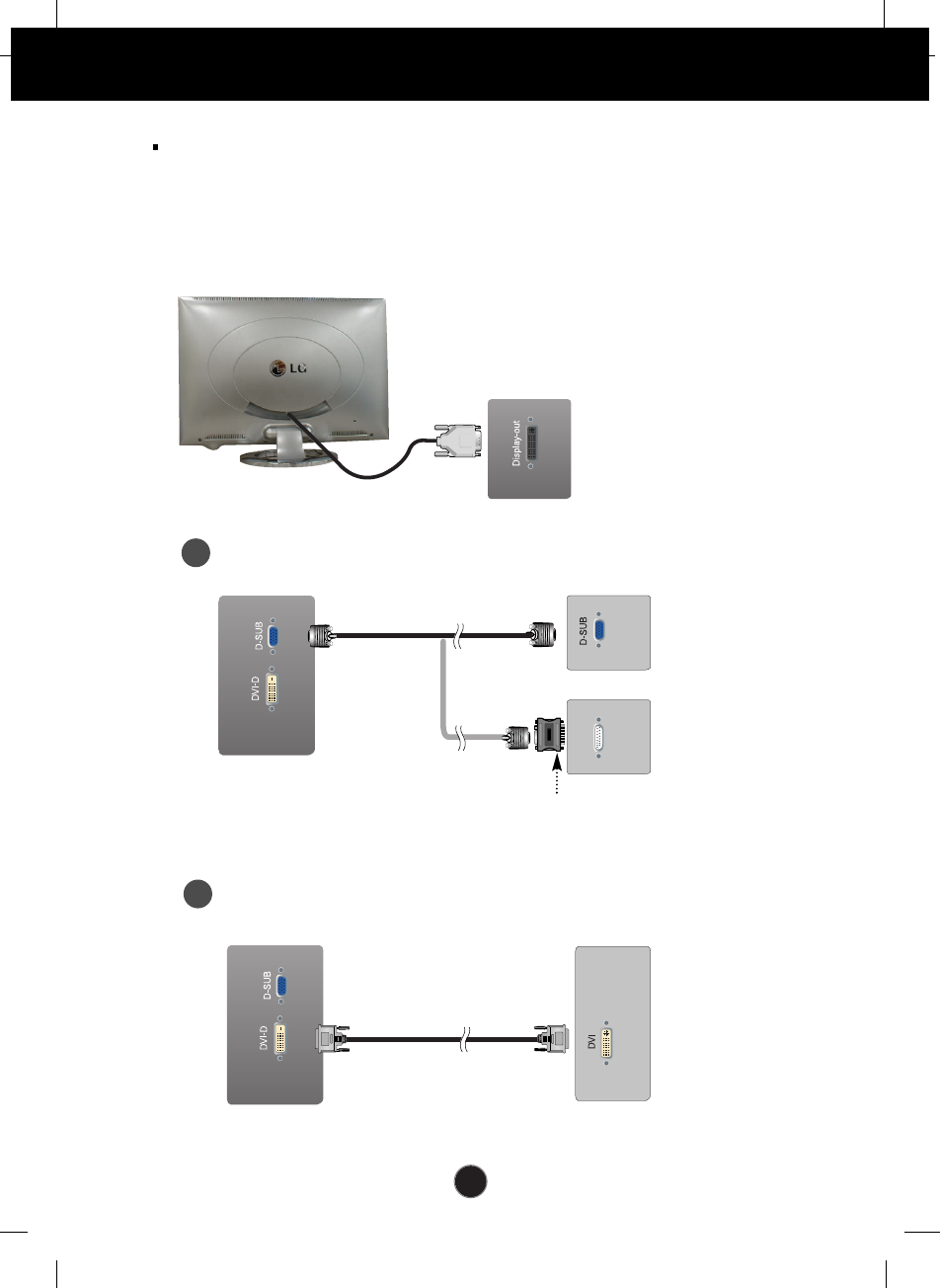
Connecting the Display
Before setting up the monitor, ensure that the power to the monitor, the
computer system, and other attached devices is turned off.
Using the Computer
1. Connect the P&D (Plug and Display) cable. When attached, tighten the
thumbscrews to secure the connection.
2. Connect the signal cable
When connecting D-SUB signal cable
When connecting DVI-D signal cable
PC
Media Station Rear
MAC
Mac adapter (not included)
For Apple Macintosh use, a separate plug adapter is needed to
change the 15 pin high density (3 row) D-sub VGA connector
on the supplied cable to a 15 pin 2 row connector.
P&D cable
Media Station Rear
Media Station Rear PC
A
B
A10
Connecting the Display
DSUB ANALOGUE
AV 1 (SCART)
AV 2 (VIDEO)
When connecting D-SUB signal cable
•
DSUB ANALOGUE: 15-pin D-sub analogue signal
When connecting DVI-D signal cable
•
DVI-D DIGITAL: DVI-D digital signal
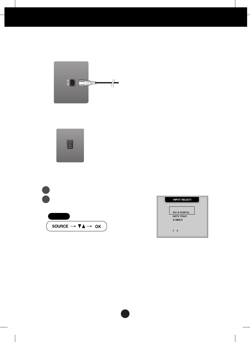
3. Connect the power cord into a proper power outlet that is easily accessible and
close to the display.
5. Select an input signal.
Press the SOURCE button
on the remote control
to select an input.
4. Turn the media station power on.
Media Station Rear
Media Station Rear
STEP
A
B
A11
Connecting the Display
AV1
AV2
(Video)
Connecting the Speakers
Connect the audio cable.
A12
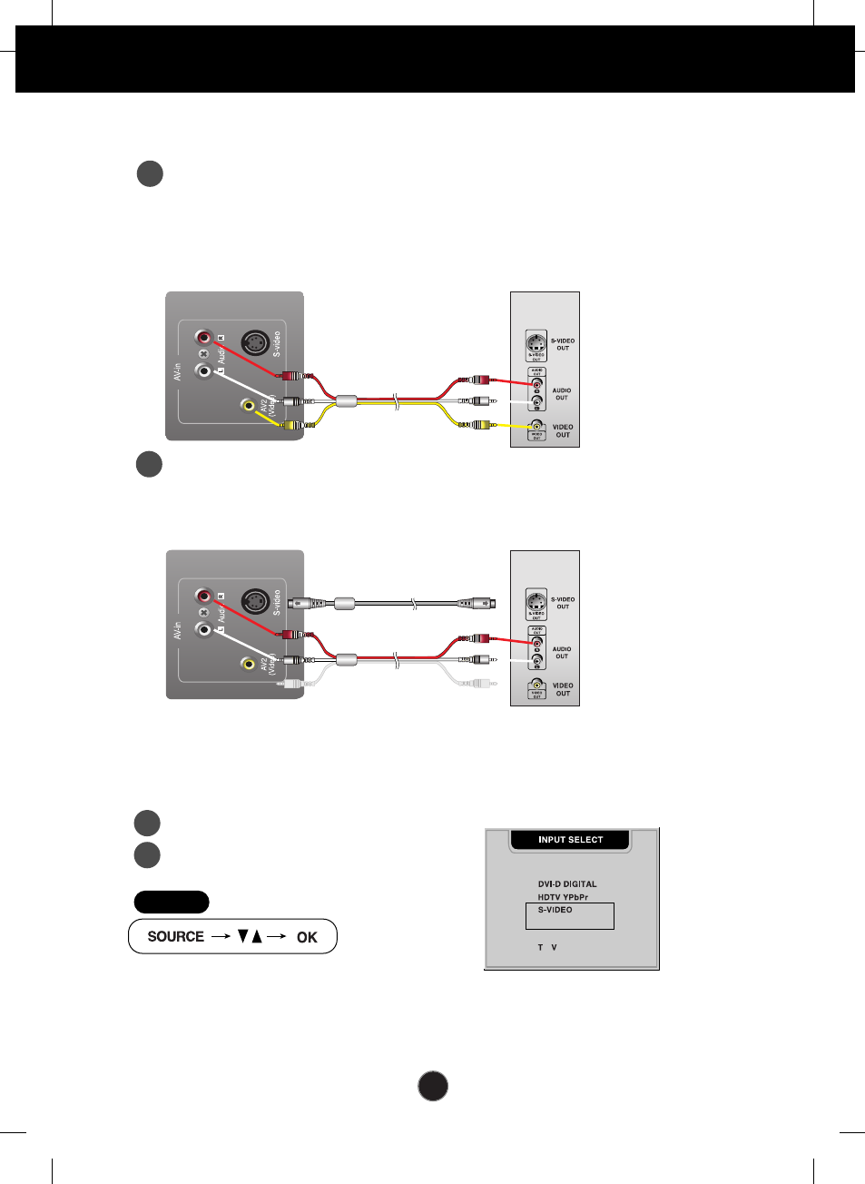
Connecting the
external equipment
Red
White
Red
White
Yellow
When connecting RCA cable
•
AV2 (VIDEO)
When connecting S-Video cable
•
S-VIDEO
2. Select an input signal.
Press the SOURCE button
on the remote control
to select an input.
Connecting the VCR/DVD
1. When connecting RCA cable
Connect the each audio/video output jack of the VCR/DVD to the
corresponding input port as shown on the Display (or Media station).
A
When connecting S-Video cable
If you connect the S-Video input port to external equipment, you can have an
improved definition image.
B
Media Station Rear VCR/DVD
Media Station Rear VCR/DVD
A
B
DSUB ANALOGUE
AV 1 (SCART)
AV 2 (VIDEO)
STEP
S-Video cable
RCA cable
A13
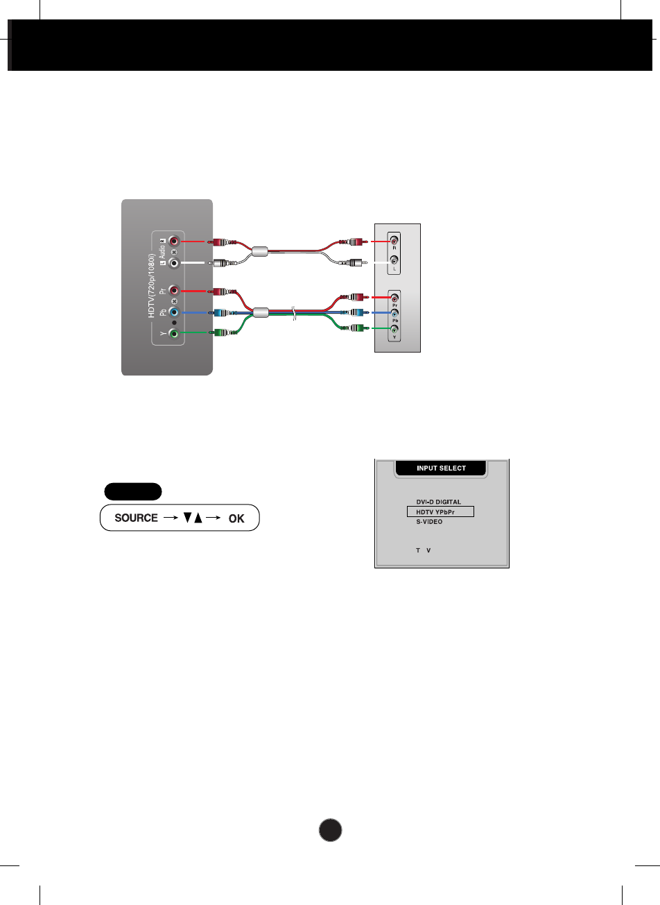
Connecting the
external equipment
Watching HDTV (720p/1080i)
HDTV cable
(not included)
Red
Blue
Green
1. Connect both HDTV cable (Y/Pb/Pr) and audio cable (Audio L/R) to the Display
(or Media station) jack and the Set-top box jack.
Audio cable
(not included)
Media Station Rear
HDTV
Set-Top
(Optional)
•
HDTV YPbPr
2. Select an input signal.
Press the SOURCE button
on the remote control
to select an input.
DSUB ANALOGUE
AV 1 (SCART)
AV 2 (VIDEO)
STEP
Red
White
A14
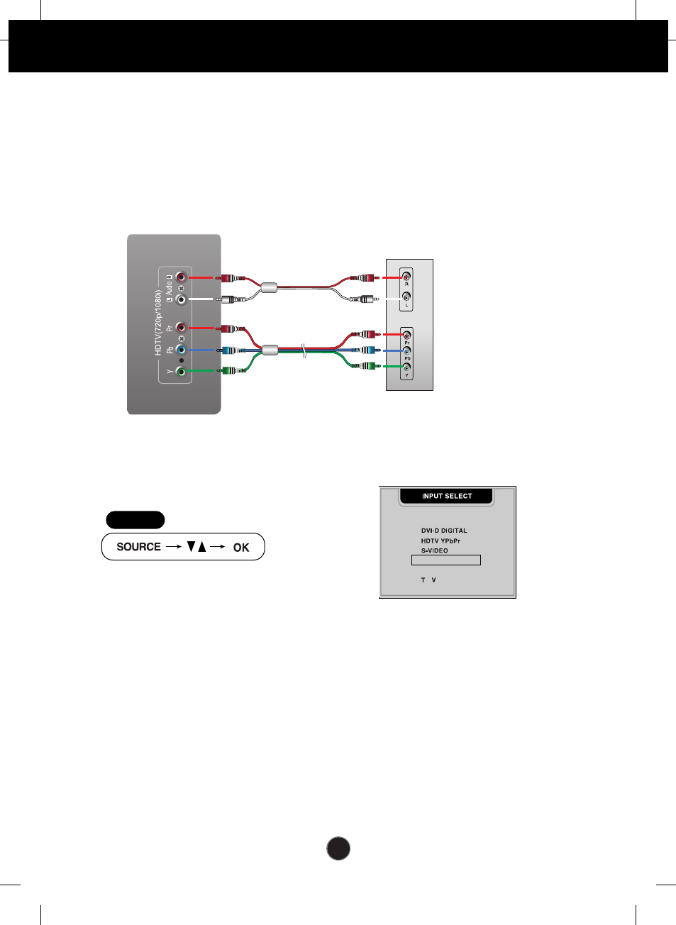
Connecting the
external equipment
•
AV1 (SCART)
2. Select an input signal.
Press the SOURCE button
on the remote control
to select an input.
Connecting the HDTV/DVD(576i only)
Take these connection steps if the HDTV/DVD player has a RCA jack and the
output is 576i only.
HDTV/DVD(576i)
DSUB ANALOGUE
AV 1 (SCART)
AV 2 (VIDEO)
STEP
1. Connect half of the SCART cable.
HDTV cable
(not included)
Red
Blue
Green
Audio cable
(not included)
HDTV
Set-Top
(Optional)
Red
White
A15
Watching TV
Antenna
(not included)
Before setting up the monitor, ensure that the power to the monitor, the
computer system, and other attached devices is turned off.
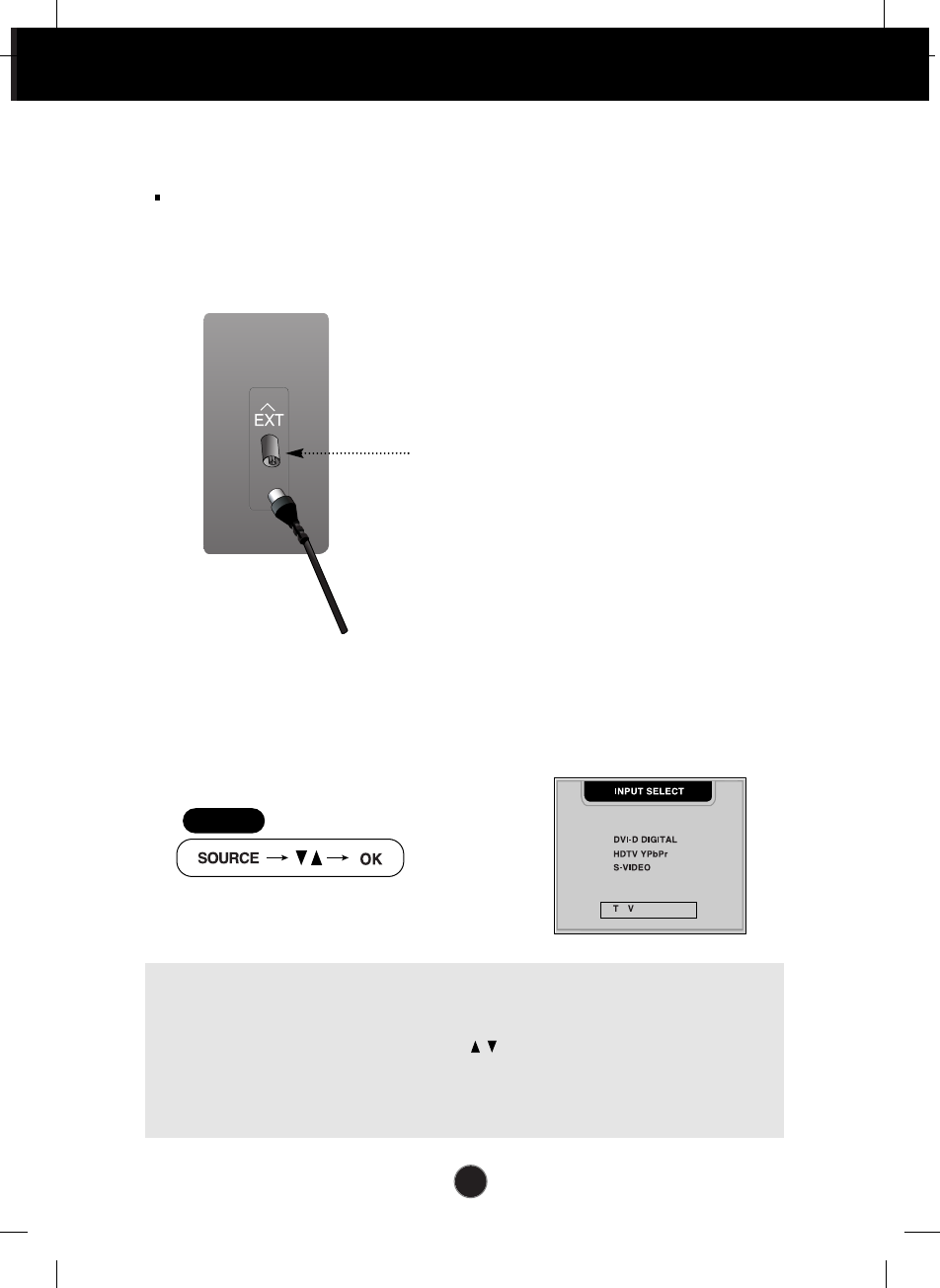
1. Connect the antenna.
TV tuner jack
Connecting the
external equipment
Media Station Rear
•
TV
2. Select an input signal.
Press the SOURCE button
on the remote control
to select an input.
DSUB ANALOGUE
AV 1 (SCART)
AV 2 (VIDEO)
STEP
AUTO AV switching
If your VCR is connected to the euroconnector and the VCR is switched to
playback, the TV will automatically change to AV1(SCART) mode. If you want to
keep watching in TV mode, press the PR ( ) Buttons or press the number
buttons. When you select a TV input signal from other sources, the AV1 (SCART)
signal will be displayed immediately if it is available. You can connect a DVD, VCR
or satellite receiver to the AV1 (SCART) terminal.
A16
Control Panel Functions
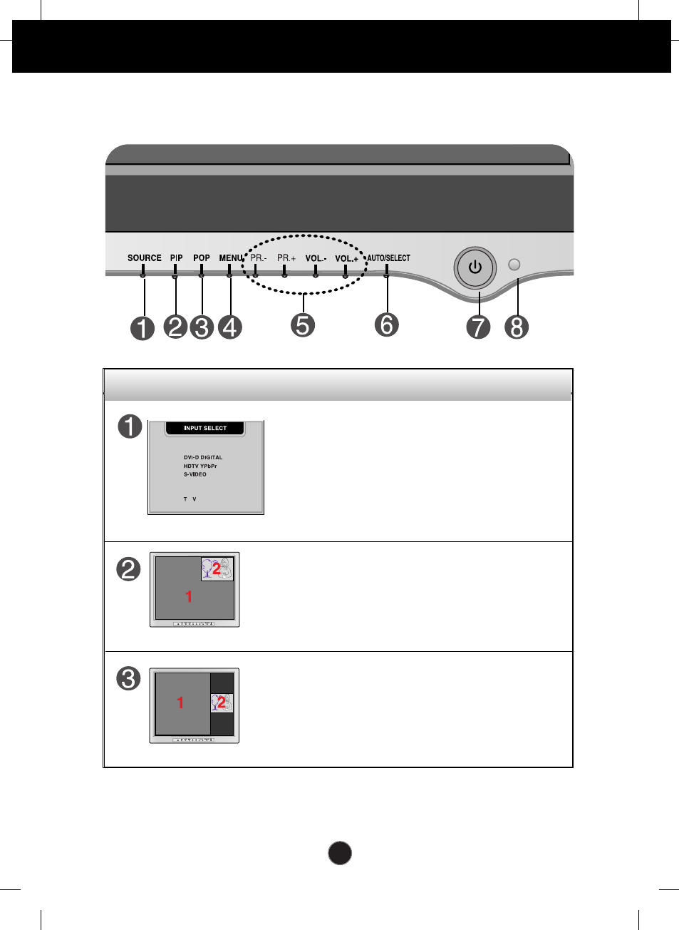
Front Panel Controls
Control Function
DSUB ANALOGUE
AV 1 (SCART)
AV 2 (VIDEO)
Use this button to select an input signal.
• DSUB ANALOGUE: 15-pin D-sub analogue signal
• DVI-D DIGITAL: DVI-D digital signal
• HDTV YPbPr: HDTV
• S-VIDEO: S video
• AV1 (SCART) : SCART
• AV2 (VIDEO) : CVBS
• TV: TV
Source Selection:
The sub-screen is changed in the order shown below.
: SMALL -> LARGE -> OFF
The positions of SOURCE 1 and SOURCE 2 can be
transposed by selecting SWAP on the remote control.
PIP (Picture in Picture) function
The sub-screen is changed in the order shown below.
: POP1 -> POP2 -> POP3 -> POP4 -> OFF
The positions of SOURCE 1 and SOURCE 2 can be
transposed by selecting SWAP on the remote control.
POP (Picture out Picture) function
A17
Control Panel Functions
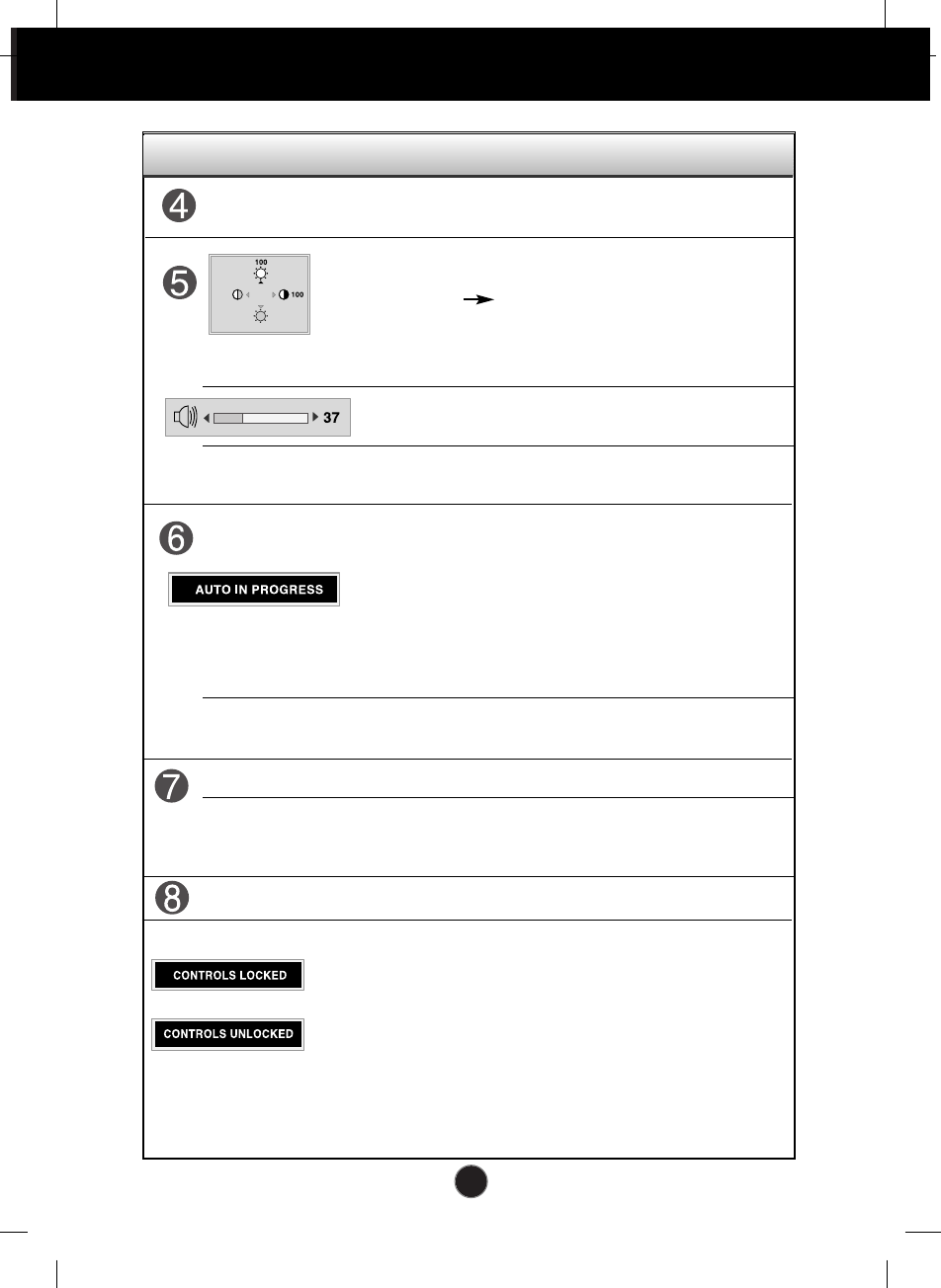
Control Function
•
Bring up Contrast and Brightness adjustment. It is
available to the PC signal inputs only.
• Use these buttons to go up and down the channel
when the TV source is available.
When adjusting your display settings, always press the
AUTO/SELECT button before entering the On Screen
Display(OSD). This will automatically adjust your display
image to the ideal settings for the current screen
resolution size (display mode). It is available to the PC
signal inputs only.
The best display mode is 1280x768 @60Hz.
AUTO adjustment function
Use these buttons to decrease or increase the volume level.
VOL. - / VOL. +
PR. - / PR. +
PR. - / PR. +
Use these buttons to choose or adjust items in
the On Screen Display.
MENU Button
Use this button to enter or exit the On Screen
Display.
Use this button to turn the display on or off.
This Indicator lights up blue when the display operates
normally. If the display is in DPM (Energy Saving) mode,
this indicator color changes to amber.
Power Button
Power (DPMS)
Indicator
Use this button to enter a selection in the On Screen
Display.
Remote Control Sensor
This function allows you to secure the current control settings,
so that they cannot be inadvertently changed. Press and hold
the MENU button and
VOL.+
button for 5 seconds: the
message “CONTROLS LOCKED”appears.
You can unlock the OSD controls at any time by pushing the
MENU button and
VOL.+
button for 5 seconds:
the message “CONTROLS UNLOCKED” will appear.
CONTROLS LOCKED/UNLOCKED :
MENU and VOL.+
PR. - / PR. + : To adjust the brightness
VOL. - / VOL. + : To adjust the contrast
A18
On Screen Display (OSD) Control Adjustment
Screen Adjustment
Making adjustments to the image size, position and operating parameters of
the display is quick and easy with the On Screen Display Control system. A
short example is given below to familiarize you with the use of the controls.
The following section is an outline of the available adjustments and selections
you can make using the OSD.
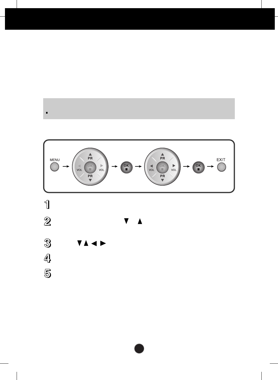
To make adjustments in the On Screen Display, follow these steps:
Press the MENU Button, then the main menu of the OSD appears.
To access a control, use the or Buttons. When the icon you want
becomes highlighted, press the OK Button.
Use the Buttons to adjust the item to the desired level.
Accept the changes by pressing the OK Button.
Exit the OSD by Pressing the EXIT Button.
NOTE
Allow the display to stabilize for at least 30 minutes before making image adjustments.
A19
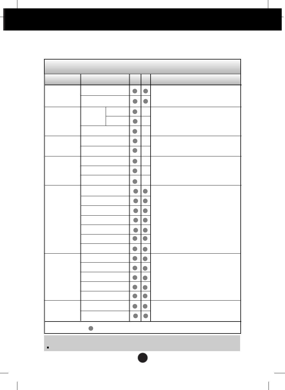
On Screen Display(OSD) Selection and Adjustment
The following table indicates all the On Screen Display control, adjustment,
and setting menus.
NOTE
The order of icons may differ depending on the model (A22~A34).
To adjust the brightness and
contrast of the screen
BRIGHTNESS
CONTRAST
COLOUR
ADJUSTMENT
IMAGE
POSITION
TRACKING
AUDIO
SETUP
PIP/POP
Main menu Sub menu A D Reference
PRESET
9300K
6500K
R/G/B(User Colour)
To adjust the position of the
screen
To customize the colour of the
screen
To customize the screen status
for a user's operating environment
To improve the clarity and
stability of the screen
BRIGHTNESS
CONTRAST
V POSITION
H POSITION
AUTO
CLOCK
PHASE
LANGUAGE
IMAGE SIZE
OSD POSITION
TRANSPARENCY
ZOOM
To adjust the PIP/POP of the
screen
Using the computer
To adjust the audio function
MUTE
VOLUME
BBE EFFECT
AVL
SSM
BASS
TREBLE
: Adjustable A : Analog Input D : Digital Input
PIP MODE
POP MODE
A20
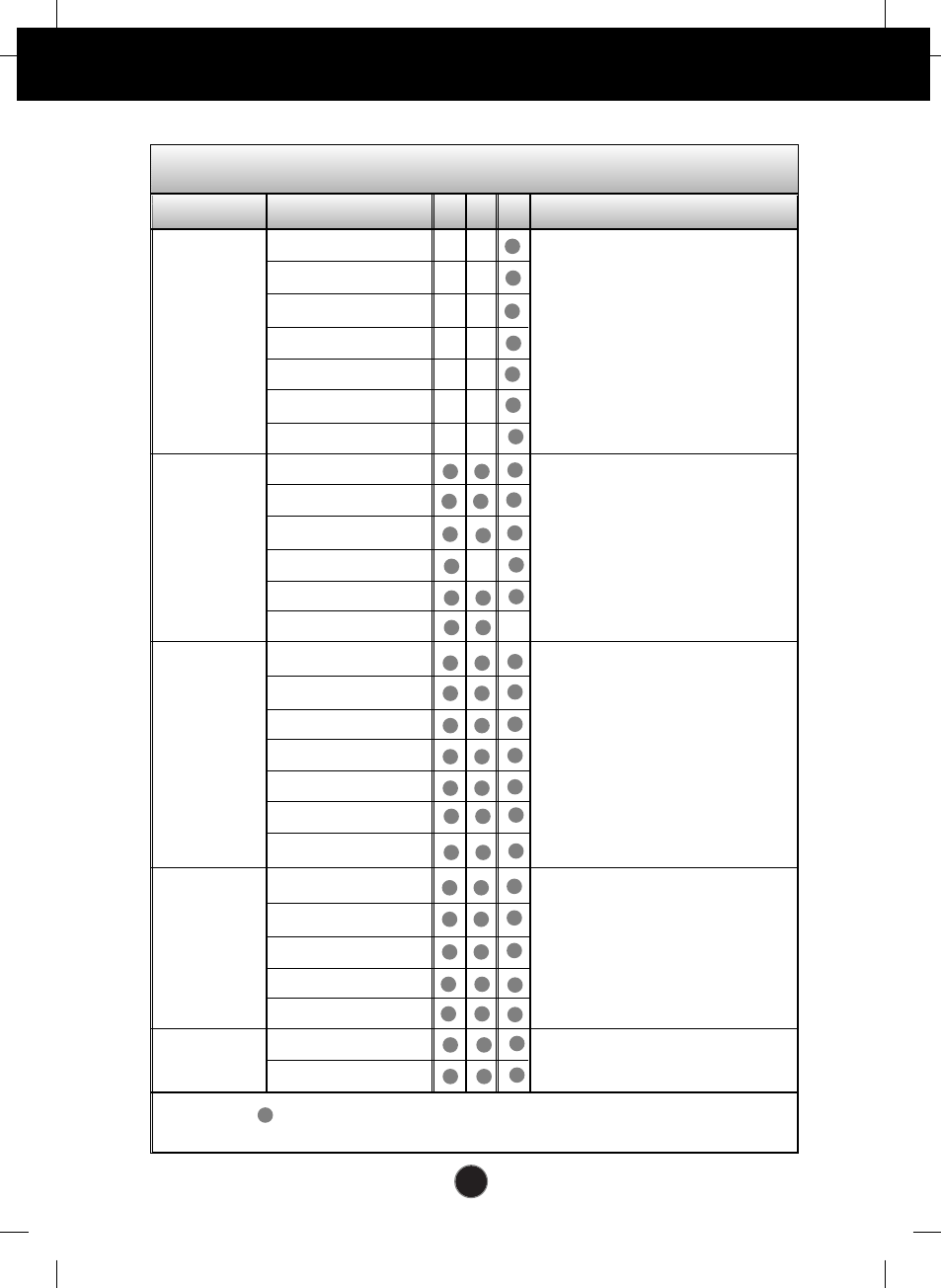
On Screen Display(OSD) Selection and Adjustment
STATION
ADJUSTMENT
AUDIO
SETUP
PIP/POP
Main menu Sub menu V H T Reference
PSM
CONTRAST
BRIGHTNESS
SHARPNESS
COLOUR
TINT
To customize the screen
status for a user's operating
environment
To improve the clarity and
stability of the screen
LANGUAGE
IMAGE SIZE
OSD POSITION
TRANSPARENCY
COLOUR
To adjust the audio function
PROGRAMME
SYSTEM
SELECT
CHANNEL
FINE TUNE
NAME
AUTO PR.
To select the TV channel
settings and adjust the
channel quality.
Using the VCR/DVD/TV/HDTV
: Adjustable V : VCR/DVD T : TV H : HDTV
MUTE
VOLUME
BBE EFFECT
AVL
SSM
BASS
TREBLE
To adjust the PIP/ POP of the
screen
PIP MODE
POP MODE
A21
On Screen Display(OSD) Selection and Adjustment
You were introduced to the procedure of selecting and adjusting an item
using the OSD system. Listed below are the icons, icon names, and icon
descriptions of the all items shown on the Menu.
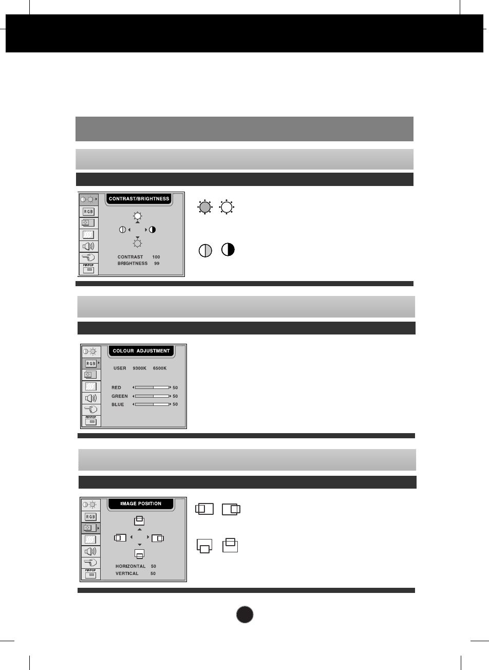
OSD Adjust Description
BRIGHTNESS
To adjust the brightness of the screen.
CONTRAST
To adjust the contrast of the screen.
To adjust the brightness and contrast of the screen
USER
9300K
6500K
RED/GREEN/BLUE
Set your own colour levels.
Select the screen colour.
• 9300K: Slightly bluish white.
• 6500K: Slightly reddish white.
To customize the colour of the screen
OSD Adjust Description
Vertical Position
To move image up and down.
Horizontal Position
To move image left and right.
To adjust the position of the screen
OSD Adjust Description
To adjust the screen when using the computer
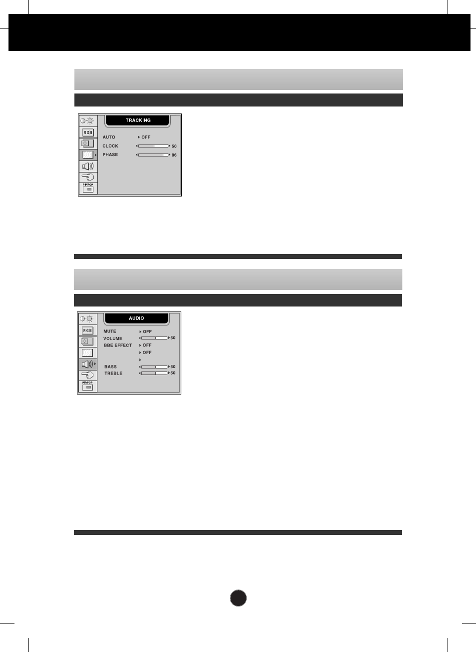
A22
On Screen Display(OSD) Selection and Adjustment
This function is suitable for analog signal
input only. This button is for the
automatic adjustment of the screen
position, clock and phase.
To minimize any vertical bars or stripes
visible on the screen background.The
horizontal screen size will also change.
To adjust the focus of the display. This
item allows you to remove any horizontal
noise and clear or sharpen the image of
characters.
AUTO
CLOCK
PHASE
To improve the clarity and stability of the screen
OSD Adjust Description
To adjust the audio function
OSD Adjust Description
Used to select mute on (means sound off)
and mute off (means sound on).
To decrease or increase volume level.
To improve the clarity and distinction of
audio quality.
Use this function to automatically adjust
volume being relayed unevenly for each
channel or signal so that the most
appropriate level can be selected.
Select a sound mode of your choice
among FLAT, MUSIC, MOVIE and
SPEECH, or select 'USER' and adjust the
values of BASS and TREBLE.
To decrease or increase bass level.
To decrease or increase treble level.
MUTE
VOLUME
BBE
EFFECT
AVL
SSM
BASS
TREBLE
AVL
SSM USER
A23
On Screen Display(OSD) Selection and Adjustment
SELECT 1028x768
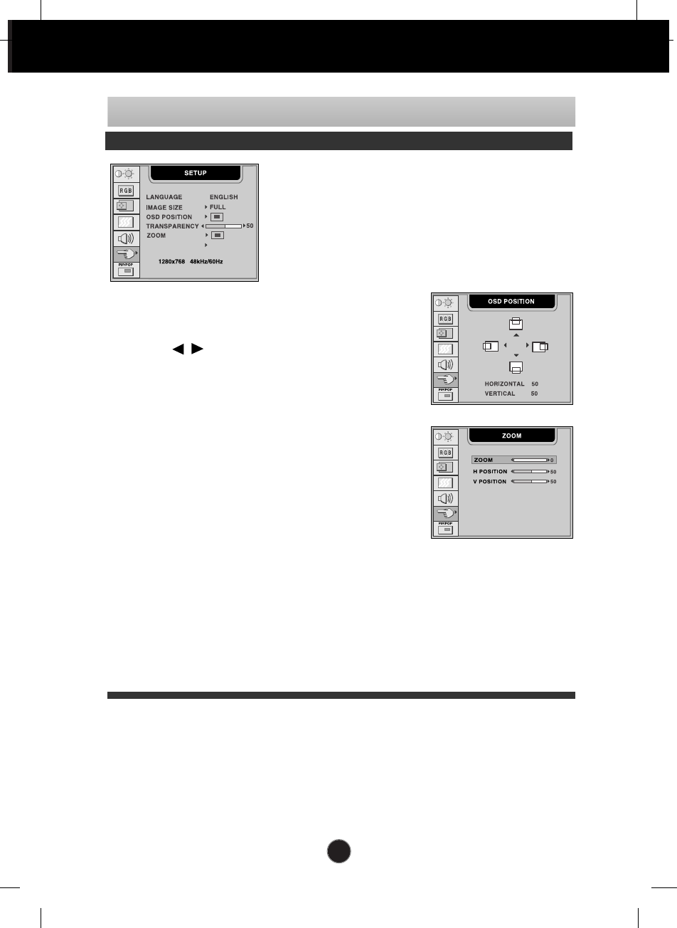
To customize the screen status for a user's operating environment
OSD Adjust Description
To choose the language in which the
control names are displayed.
To select the image size of the screen.
FULL/4:3/ SPECTACLE /1:1/AUTO
The SPECTACLE menu is used when
the resolution ratio is 4:3 (640x480,
800x600 and 1024x768)
OSD POSITION
To adjust position of the OSD window on the screen.
Press the button to display the submenu
for OSD POSITION.
TRANSPARENCY
To adjust the transparency of the OSD menu screen.
ZOOM
To adjust horizontal and vertical image size
simultaneously. If you want to move the zooming
point, use the H/V POSITION function in the sub-menu.
However, if the monitor turns off when zooming in
and out the screen, the monitor will be returned to
original screen.
SELECT *
This menu will be enabled only when the resolution is 1280x768 @60Hz,
1024x768 @60Hz, 640x480 @70Hz or 848x480 @70Hz.
If the screen is not displayed properly, adjust the resolution as follows. If you set
to the "Auto", the proper resolution will be automatically selected.
• 1280x768/1024x768/AUTO: Use this menu when the resolution is 1280x768
@60Hz or 1024x768 @60Hz.
• 640x480/848x480/AUTO: Use this menu when the resolution is 640x480
@70Hz or 848x480 @70Hz.
LANGUAGE
IMAGE SIZE
A24
On Screen Display(OSD) Selection and Adjustment
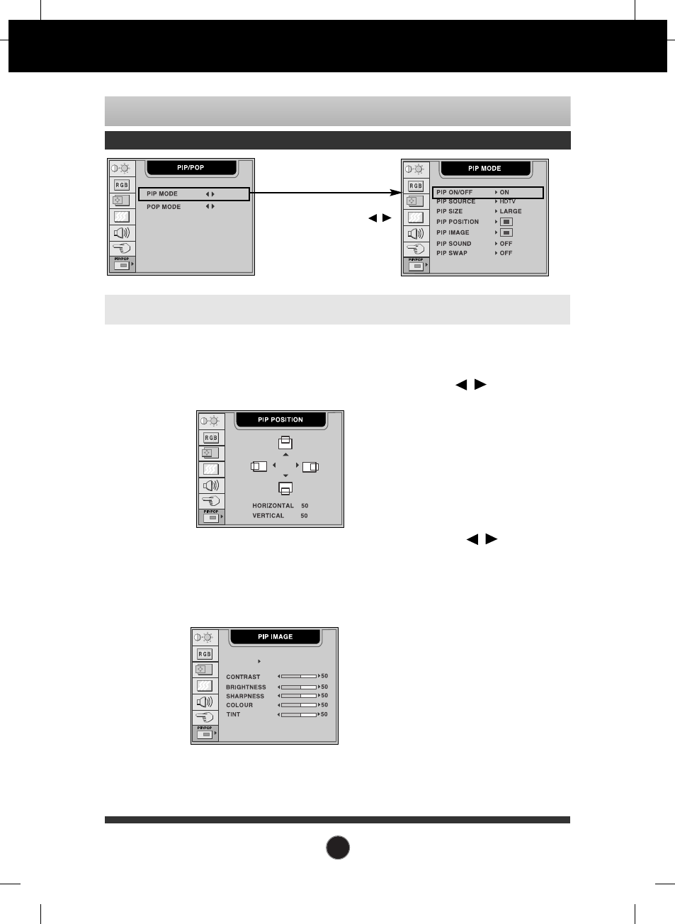
After selecting ON in the PIP ON/OFF menu, the following menu items can be adjusted.
To adjust the image of the PIP screen; Press the button to
display the submenu for PIP IMAGE. The items of the sub-menu may
vary depending on the type of the source.
To adjust the PIP(Picture in Picture) of the screen
OSD Adjust Description
PIP SOURCE
PIP SIZE
PIP POSITION
PIP IMAGE
PIP SOUND
PIP SWAP
CONTRAST To adjust the contrast of the screen.
BRIGHTNESS To adjust the brightness of the screen.
SHARPNESS To adjust the clearness of the screen.
In case the PIP source is HDTV,
SHARPNESS is not supported.
COLOUR To adjust the coloUr to desired level.
TINT To adjust the tint to desired level.
This function is available only in
NTSC broadcasting mode.
PSM :
Select a picture mode of your choice among DYNAMIC, STANDARD,
MILD and GAME, or select 'USER' and adjust the values of CONTRAST,
BRIGHTNESS, SHARPNESS, COLOUR and TINT.
To select an input signal for PIP.
To adjust the size of the PIP screen: SMALL/LARGE
To adjust the position of PIP screen. Press the button to
display the submenu for PIP POSITION.
PSM USER
To turn the PIP sound on/off.
To switch the main-screen and sub-screen in PIP mode.
To adjust the PIP MODE submenu
function, Press the OK -->
button on the remote control
A25
On Screen Display(OSD) Selection and Adjustment
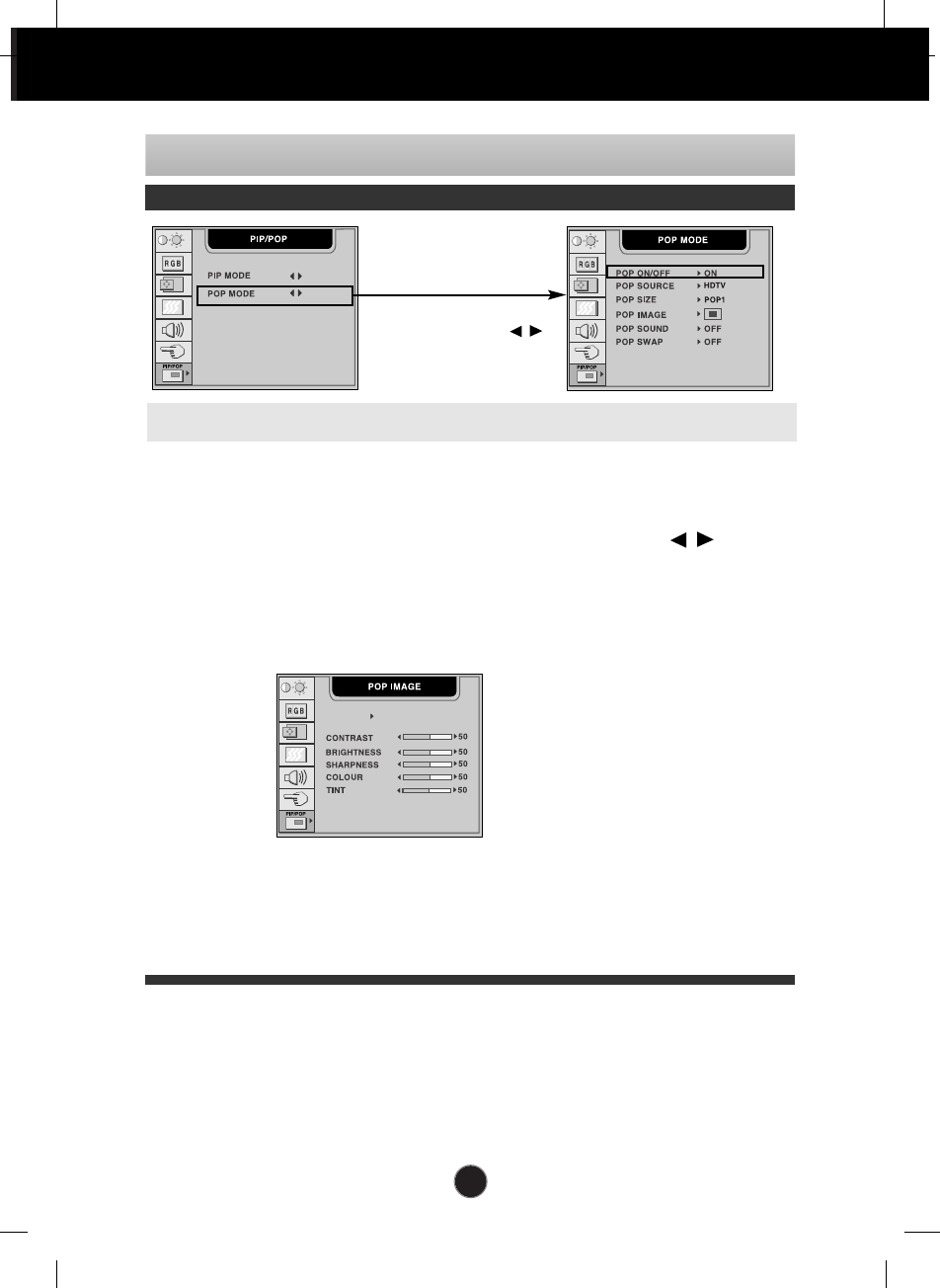
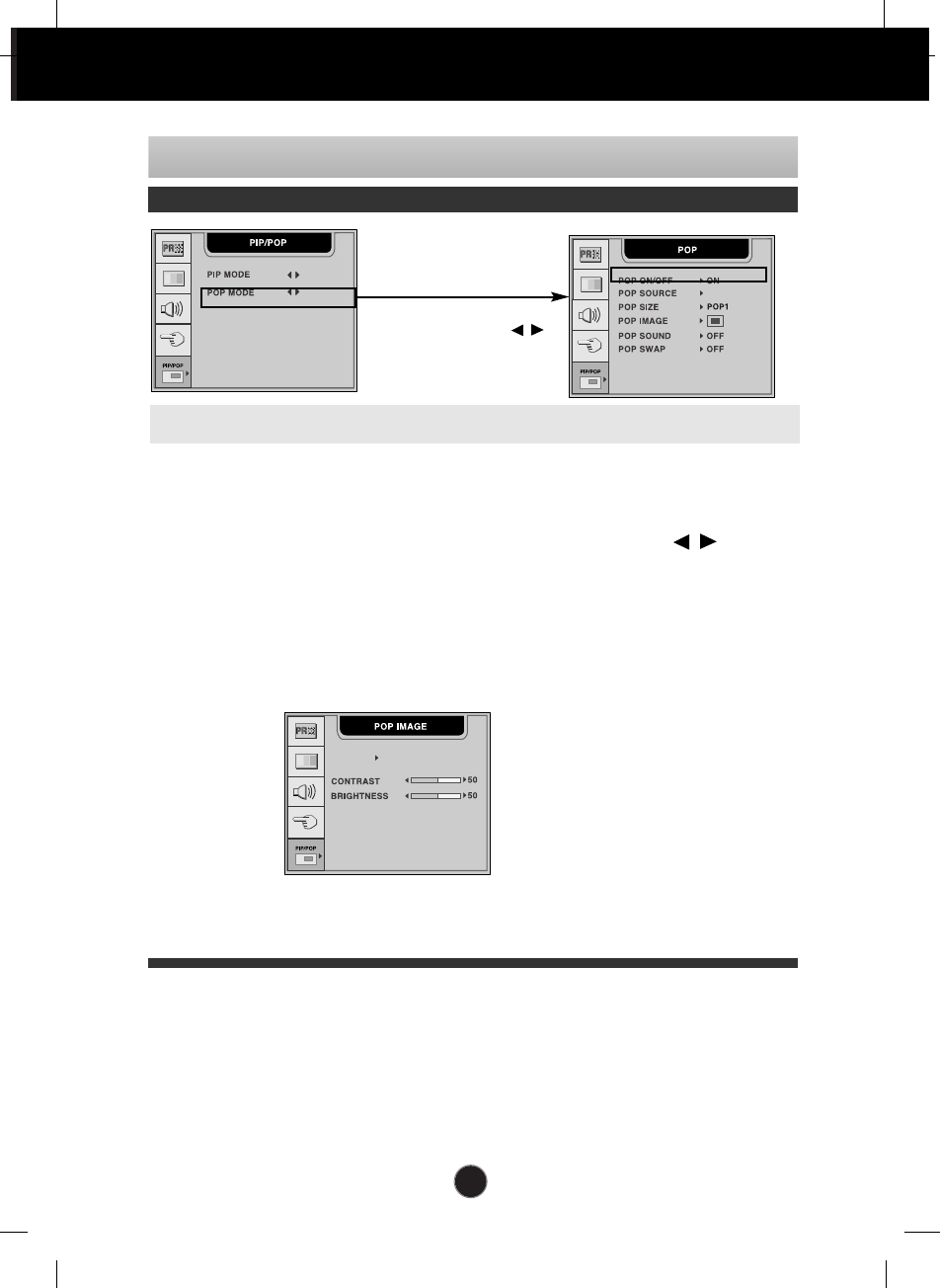
To adjust the POP(Picture out Picture) of the screen
OSD Adjust Description
To select an input signal for POP.
To adjust the size of the POP screen: POP1/POP2/POP3/POP4
To adjust the image of the POP screen; Press the button to
display the submenu for POP IMAGE. The items of the sub-menu
may vary depending on the type of the source.
To turn the POP sound on/off.
To switch the main-screen and sub-screen in POP mode.
POP SOURCE
POP SIZE
POP IMAGE
POP SOUND
POP SWAP
After selecting ON in the POP ON/OFF menu, the following menu items can be adjusted.
PSM USER
To adjust the POP MODE submenu
function, Press the OK -->
button on the remote control
CONTRAST To adjust the contrast of the screen.
BRIGHTNESS To adjust the brightness of the screen.
SHARPNESS To adjust the clearness of the screen.
In case the POP source is
HDTV, SHARPNESS is not
supported.
COLOUR To adjust the coloUr to desired level.
TINT To adjust the tint to desired level.
This function is available only in
NTSC broadcasting mode.
PSM :
Select a picture mode of your choice among DYNAMIC, STANDARD,
MILD and GAME, or select 'USER' and adjust the values of CONTRAST,
BRIGHTNESS, SHARPNESS, COLOUR and TINT.
A26
On Screen Display(OSD) Selection and Adjustment
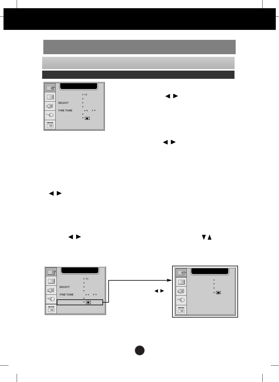
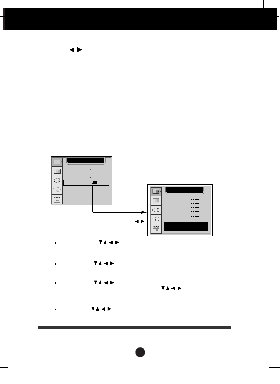
To select TV channel settings and adjust the channel quality
OSD Adjust Description
To change the channel.
Press the buttons to select the TV
system of the country or part of the world
from where you want to receive the TV
channels.
To select the channel reception type.
: V/UHF / CABLE
Press the button to select C-CH for
aerial channels or S-CH for cable
channels.
If you know the C-(01~69) or S-channel
number(01~47), enter it derectly with the
digit buttons 0 to 9.
FINE TUNE
In case of poor reception, you can improve the reception by fine tuning. Use the
buttons to fine tune for the best picture and sound.
NAME
To see the assigned channel name.
It is possible to change the name stored in the memory or to assign a name to a TV
channel which has not yet been entered. A name with up 5 letters or numbers can be
given to the programme numbers 0 to 99.
Press the buttons to move cursor to be changed. -> Press the buttons
to select a character.(space, number 0~9, and alphabet A~Z) -> Press the
AUTO/SELECT button (or OK button on the remote control).
AUTO PR.
PROGRAMME
SYSTEM
SELECT
CHANNEL
STATION
PROGRAMME
SYSTEM
CHANNEL
NAME
AUTO PR.
BG
V/UHF
4
C 04
PR
PR
STATION
PROGRAMME
SYSTEM
CHANNEL
NAME
AUTO PR.
BG
V/UHF
4
C 04
PR
PR
AUTO PROGRAMME
STORAGE FROM 2
START OFF
EDIT
SYSTEM BG
PR
PR
Follow these steps : Select TV system -> Select a channel number from where you
want to storing for new channels. -> Press ON to start auto programming.
To adjust the AUTO PR. submenu
function, Press the OK -->
button on the remote control
To adjust the screen when using the VCR/DVD/HDTV/TV
A27
On Screen Display(OSD) Selection and Adjustment
SYSTEM
Press the buttons to select the TV system of the country or part of the world
from where you want to receive the TV channels.
If you want to receive 'SECAM L' channel, change the SYSTEM menu to 'L' before
launching an automatic search.
STORAGE FROM
To select a channel number or enter the channel number with the number buttons
from where you want to start searching for new channels. If e.g. you want to keep the
channels 1 to 10 stored earlier, enter channel number 11. Your TV search for new
channels from number 11 onwards.
START
Select the ON to start automatic programming. all available TV channels are searched
for and stored automatically. To stop auto programming, press the MENU button.
When auto programming is completed, the programme list menu appears.
EDIT
AUTO PROGRAMME
STORAGE FROM 2
START OFF
EDIT
SYSTEM BG
PR
PR
PROGRAMME EDIT
0
1
2
3
C 01
C 04
C 25
4
5
6
7
8
9
DELETE COPY
MOVE SKIP
PR
PR
DELECT: Press the buttons to select a TV channel to be deleted.
-> Press the red key on the remote control twice. -> The selected TV channel number is
deleted, all the following channels are shifted up one position.
COPY: Press the buttons to select a TV channel to be copyed. -> Press the
green key on the remote control. All the following channel numbers are shifted down one
position.
MOVE: Press the buttons to select a channel number to be moved. -> Press
the yellow key on the remote control. -> Press the buttons to move the TV
channel to the desired channel number. -> Press the yellow key again to release this
function.
SKIP: Press the buttons to select a channel number to be skipped. -> Press
the blue key on the remote control. The skipped TV channel is displayed in blue. -> Press
the blue key again.
To adjust the EDIT submenu
function, Press the OK -->
button on the remote control
A28
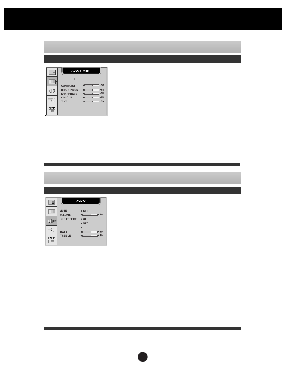
To improve the clarity and stability of the screen
OSD Adjust Description
Select a picture mode of your choice among
DYNAMIC, STANDARD, MILD and GAME, or
select 'USER' and adjust the values of
CONTRAST, BRIGHTNESS, SHARPNESS,
COLOUR and TINT.
To adjust the contrast of the screen
To adjust the brightness of the screen.
To adjust the clearness of the screen.
To adjust the colour to desired level.
To adjust the tint to desired level.
This
function is available only in NTSC
broadcasting mode.
PSM
CONTRAST
BRIGHTNESS
SHARPNESS
COLOUR
TINT
PR
PR
PSM USER
On Screen Display(OSD) Selection and Adjustment
To adjust the audio function
OSD Adjust Description
PR
PR
AVL
SSM USER
Used to select mute on (means sound off)
and mute off (means sound on).
To decrease or increase volume level.
To improve the clarity and distinction of
audio quality.
Use this function to automatically adjust
volume being relayed unevenly for each
channel or signal so that the most
appropriate level can be selected.
Select a sound mode of your choice
among FLAT, MUSIC, MOVIE and
SPEECH, or select 'USER' and adjust the
values of BASS and TREBLE.
To decrease or increase bass level.
To decrease or increase treble level.
MUTE
VOLUME
BBE
EFFECT
AVL
SSM
BASS
TREBLE
A29
FULL
You can enjoy the picture (format of 4:3) or general TV in 16:9 mode.
4:3
This picture format is 4 to 3 of general TV
SPECTACLE
This function provides different areas of the screen with a varied ratio, so that the ratio at the
central area is close to 4:3 and near the edges it exceeds 16:9. Since most people
concentrate their focus upon the central area of the screen, they do not clearly recognize a
nonlinear expansion of the image near the edges of the display. Therefore a 4:3 image can fit
into the wide screen naturally.
ZOOM 1/ZOOM 2
Zoom 1 and 2 are functions, which keeps the input ratio constant at 16:9 while zooming in;
these functions, unlike conventional zoom in function, minimize the image distortion usually
seen in the zooming process.
Input source can be controlled only in AV1 (SCART), AV2 (VIDEO), TV, S-VIDEO states.
AUTO
When your set receives a wide screen signal, it will automatically change to the picture format
to be sent.
On Screen Display(OSD) Selection and Adjustment
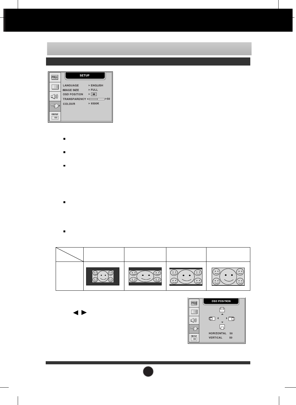
To customize the screen status for a user's operating environment
OSD Adjust Description
LANGUAGE
IMAGE SIZE
[example]
Image
Size 4:3
16:9
Screen
ZOOM1FULL ZOOM2
Input
Source
To choose the language in which the control
names are displayed.
To select the image size of the screen.
FULL/4:3/ SPECTACLE /ZOOM1/ZOOM2/AUTO.
SPECTACLE, ZOOM1, ZOOM2 and AUTO
functions are useful for TV or motion
pictures, but not suitable for PC
environments such as computer graphics or
word processing.
OSD POSITION
To adjust position of the OSD window on the screen.
Press the button to display the submenu
for OSD POSITION.
TRANSPARENCY
To adjust the transparency of the OSD menu screen.
COLOUR
To select the screen colour.
• 9300K: Slightly bluish white. • 6500K: Slightly reddish white.
A30
To
On Screen Display(OSD) Selection and Adjustment
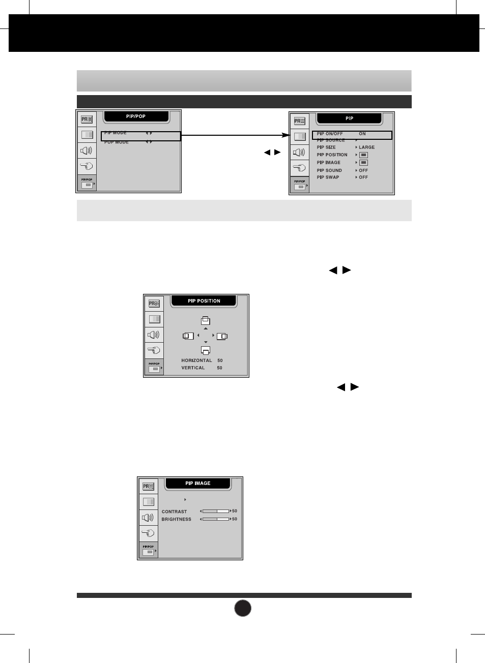
After selecting ON in the PIP ON/OFF menu, the following menu items can be adjusted.
To adjust the image of the PIP screen; Press the button to
display the submenu for PIP IMAGE. The items of the sub-menu may
vary depending on the type of the source. In case the PIP source is
D-SUB or DVI-D, PSM, COLOUR and TINT MENU are not
supported.
To adjust the PIP(Picture in Picture) of the screen
OSD Adjust Description
PIP SOURCE
PIP SIZE
PIP POSITION
PIP IMAGE
PIP SOUND
PIP SWAP
CONTRAST To adjust the contrast of the screen.
BRIGHTNESS To adjust the brightness of the screen.
COLOUR To adjust the colour to desired level.
TINT To adjust the tint to desired level.
This function is available only in
NTSC broadcasting mode.
To select an input signal for PIP.
To adjust the size of the PIP screen: SMALL/LARGE
To adjust the position of PIP screen. Press the button to
display the submenu for PIP POSITION.
DSUB ANALOGUE
PSM USER
To turn the PIP sound on/off.
To switch the main-screen and sub-screen in PIP mode.
To adjust the PIP MODE submenu
function, Press the OK -->
button on the remote control
PSM :
Select a picture mode of your choice among DYNAMIC, STANDARD,
MILD and GAME, or select 'USER' and adjust the values of CONTRAST,
BRIGHTNESS, SHARPNESS, COLOUR and TINT.
A31
To
On Screen Display(OSD) Selection and Adjustment
DSUB ANALOGUE
To adjust the POP(Picture out Picture) of the screen
OSD Adjust Description
To select an input signal for POP.
To adjust the size of the POP screen: POP1/POP2/POP3/POP4
To adjust the image of the POP screen; Press the button to
display the submenu for POP IMAGE. The items of the sub-menu
may vary depending on the type of the source. In case the POP
source is D-SUB or DVI-D, PSM, COLOUR and TINT MENU are not
supported.
To turn the POP sound on/off.
To switch the main-screen and sub-screen in POP mode.
POP SOURCE
POP SIZE
POP IMAGE
POP SOUND
POP SWAP
After selecting ON in the POP ON/OFF menu, the following menu items can be adjusted.
PSM USER
CONTRAST To adjust the contrast of the screen.
BRIGHTNESS To adjust the brightness of the screen.
COLOUR To adjust the colour to desired level.
TINT To adjust the tint to desired level.
This function is available only in
NTSC broadcasting mode.
To adjust the POP MODE submenu
function, Press the OK -->
button on the remote control
PSM :
Select a picture mode of your choice among DYNAMIC, STANDARD,
MILD and GAME, or select 'USER' and adjust the values of CONTRAST,
BRIGHTNESS, COLOUR and TINT.
A32
Troubleshooting
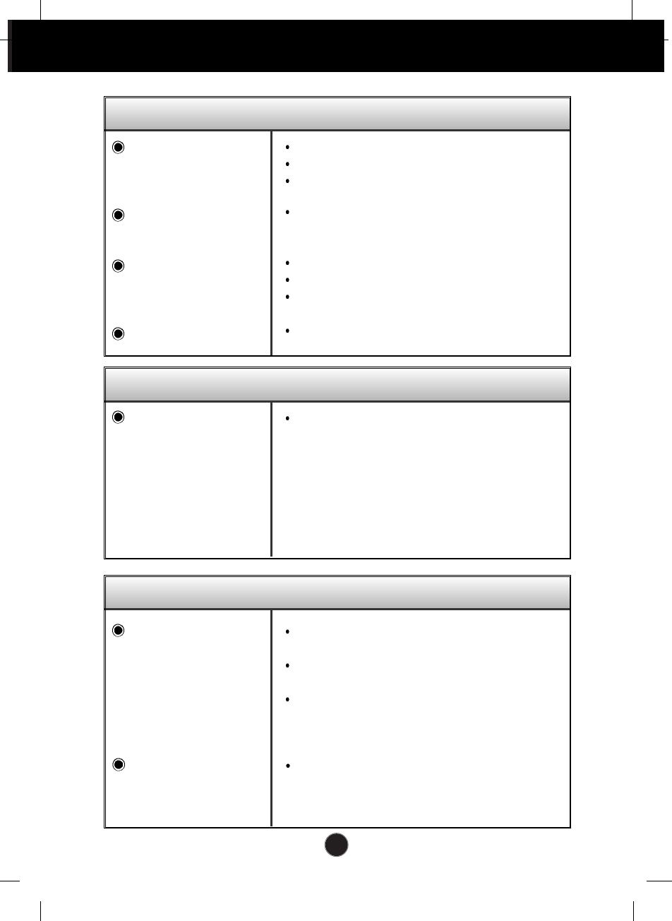
No image appears
Check the following before calling for service.
No image appears
Check and see if the power cord is connected
properly to the power outlet.
Press the Power button.
Adjust the brightness and the contrast.
If the display is in power saving mode, try moving
the mouse or pressing any key on the keyboard to
bring up the screen.
This message appears when the signal from the PC
(video card) is out of horizontal or vertical frequency
range of the display. See the 'Specifications' section
of this manual and configure your display again.
* Max Resolution
1280 x 1024 @60Hz
Check if the HDTV resolution of your set top box is
set at 480i/576i. If so, reconfigure it to
576p/720p/1080i
Check if connection is being made via the D-SUB
cable. If HDTV is connected via D-SUB cable, the
interface method and PAL (50 Hz) are not
supported. Use the HDTV port (component) instead.
This message appears when the signal cable
between your PC and your display is not connected.
Check the signal cable and try again.
Press the SOURCE button on the remote control
and select and input signal connected.
Is the power cord of the
display connected?
Is the power indicator
light on?
When the power is on
with the power
indicator lighting blue,
does the screen appear
dark?
(Display:blue, Media
station:blue)
Is the power indicator
amber?
(Display:amber,
Media station:blue)
Do you see an "OUT
OF RANGE" message
on the screen?
Does the “OUT OF
RANGE” message
appear when you have
set the main source as
HDTV?
Do you see a "CHECK
SIGNAL CABLE "
message on the screen?
A33
Troubleshooting
Display image is incorrect
Display Position is
incorrect.
Display size is not
correct in the PC mode.
On the screen
background, vertical
bars or stripes are
visible.
Any horizontal noise
appearing in any
image or characters
are not clearly
portrayed.
The screen color is
mono or abnormal.
The screen blinks.
Press the AUTO button to automatically adjust
your display image to the ideal setting.
If the results are unsatisfactory, adjust the image
position using the H position and V position
icon in the on screen display.
Check Control Panel --> Display --> Settings
and see if the frequency or the resolution were
changed. If yes, readjust the video card to the
recommend resolution.
If the resolution is 1280x768 @60Hz, 1024x768
@60Hz, 640x480 @70Hz or 848x480 @70Hz,
select the SELECT menu among SETUP OSD
menu to set the proper resolution.
If the resolution is 1280x768 @60Hz or
1024x768 @60Hz: Select one of
1280x768/1024x768/AUTO.
If the resolution is 640x480 @70Hz or 848x480
@70Hz: Select one of 640x480/848x480/AUTO.
Press the AUTO button to automatically adjust
your display image to the ideal setting.
If the results are unsatisfactory, decrease the
vertical bars or stripes using the CLOCK icon in
the on screen display.
Press the AUTO button to automatically adjust
your display image to the ideal setting.
If the results are unsatisfactory, decrease the
horizontal bars using the PHASE icon in the on
screen display.
Check Control Panel --> Display --> Settings
and adjust the display to the recommended
resolution or adjust the display image to the ideal
setting. Set the color setting higher than 24 bits
(true color).
Check if the signal cable is properly connected
and use a screwdriver to fasten if necessary.
Make sure the video card is properly inserted in
the slot.
Set the color setting higher than 24 bits (true
color) at Control Panel - Settings.
Check if the screen is set to interlace mode and if
yes, change it to the recommend resolution.
A34
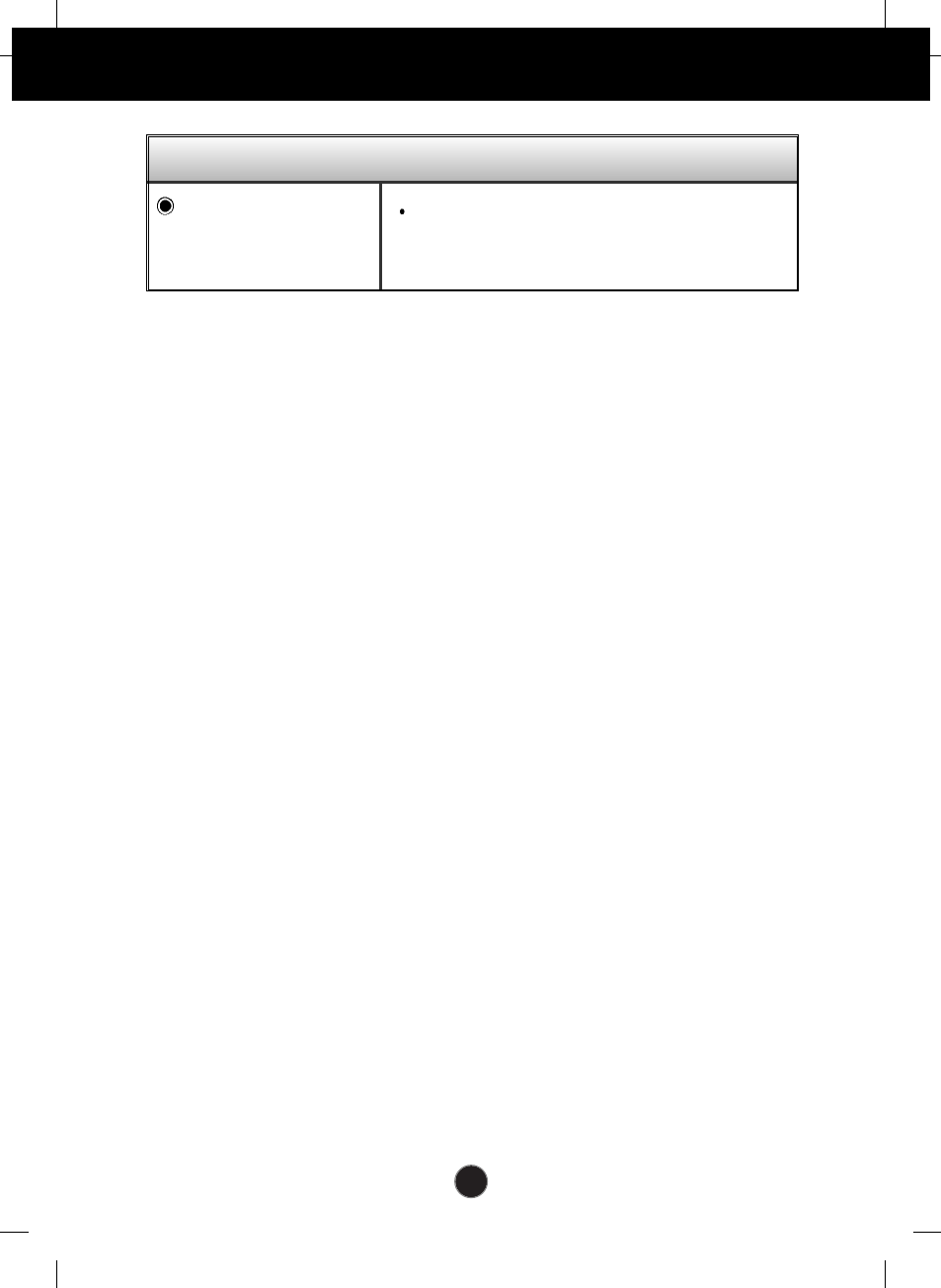
“IMAGE SIZE” function on OSD menu does not work.
Check if POP function is in use. While POP is in
use, IMAGE SIZE function becomes disabled.
“IMAGE SIZE” function
on OSD menu does not
work?
Have you installed the display driver?
Have you installed the
display driver?
Do you see an
"Unrecognized monitor,
Plug&Play (VESA DDC)
monitor found"
message?
Be sure to install the display driver from the
display driver CD (or diskette) that comes with
your display. Or, you can also download the
driver from our web site: http://www.lge.com.
Make sure to check if the video card supports
Plug&Play function.
Troubleshooting
Display image is incorrect
Is the H/V position not
adjustable from the
ZOOM function?
Has the screen size of
your PC changed
automatically?
Is the sound not
displayed on the TV
channel indication
window?
In the PC signal
source, is the
brightness of the main
screen different from
that of the sub-
screen?
Check if the ZOOM value is set at ‘0’. In case
the ZOOM value is set at ‘0’, the H/V position
will not be adjustable.
If the IMAGE SIZE is not full-screen when you
use next your PC, execute POP and it will
change back to regular settings.
Check if the TV sound is set at MONO. In case
the TV sound is at MONO, the sound will not be
displayed.
Since the BRIGHTNESS and COLOUR of a
sub-screen can be adjusted in the PIP/POP
IMAGE of the PIP/POP menus, it may be
different from the main screen.
A35
Troubleshooting
TV function
TV signal is not
received.
Is the sound not
displayed on the TV
channel indication
window?
Check the channel system and make sure you
chose the correct channel system.
Check the AUTO CHANNEL function to
automatically search the available channels.
Check and see if the TV adapter is properly
connected between your display and antenna
cable.
Check if the TV sound is set at ‘MONO’. In
case the TV SOUND is at ‘MONO’, the sound
will not be displayed.
Check if the audio cable is correctly connected.
Check the volume level.
Check if the sound source is correctly selected.
Check if the SOUND is ON in the PIP/POP OSD
menu.
Adjust the TREBLE to an appropriate level.
Adjust the BASS to an appropriate level.
Select the BBE EFFECT to an appropriate level.
Check the volume level.
No sound.
No sound in PIP /POP
mode.
Sound is too high
pitched or too low
piched.
Sound level is too low.
Audio function
Do you see a "CONTROLS LOCKED" message on the screen.
Do you see
“CONTROLS LOCKED”
when you push MENU
button?
You can secure the current control settings, so
that they cannot be inadvertently changed. You
can unlock the OSD controls at any time by
pushing the MENU button and
VOL.+
button
for 5 seconds: the message “CONTROLS
UNLOCKED”will appear. It is not possible to
configure this function with the remote control
buttons. You can only do so from the monitor.
A36
Troubleshooting
“ZOOM” function on OSD menu does not work.
Check the current resolution on your PC. If the
resolution is higher than 1280x768, the "Zoom"
function will not be supported.
Do you see a "NOT
SUPPORTED"
message on the
screen?
A37
NOTE
Information in this document is subject to change without notice.
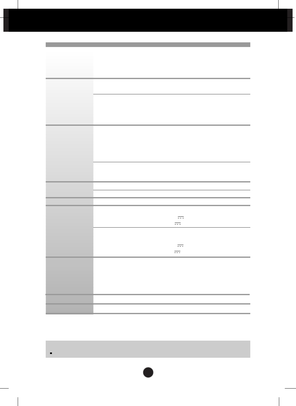
Specifications
23 inches (58.4cm) Flat Panel Active matrix-TFT LCD
Anti-Glare coating
23 inches viewable
0.258mm pixel pitch
Horizontal Freq. 30 - 66kHz (Automatic)
Vertical Freq. 56 - 75Hz (Automatic)
Input Form Separate TTL, Positive/Negative
Composite TTL, Positive/Negative
SOG (Sync On Green)
Digital
Signal Input 15 pin D-Sub Connector
DVI - D connector (Digital)
Composite video
S video
HDTV, TV
Input Form RGB Analog (0.7Vp-p/75ohm),
Digital,
S-VIDEO, CVBS, Y Pb Pr (Y,Cb,Cr)
Max 1280 x 1024 @60Hz
Recommend 1280 x 768 @60Hz
DDC 2B
Display
Input DC 24V 4.0A
DC 5V 0.5A
Media station
Input AC 100-240V~ 50/60Hz 1.5A
Output DC 24V 4.0A
DC 5V 0.5A
Normal :
110W
Stand-by/Suspend
≤5W
DPMS Off ≤3W
Power switch Off ≤3W
Power cut-off switch off ≤1W
0˚~20˚
Attached( O ), Detached ( )
Display
Sync Input
Video Input
Resolution
Plug&Play
Power Input
Power
Consumption
Tilt Range
Tilt Stand
A38
Display
(with tilt stand)
Width 58.75cm / 23.13 inches
Height 44.65 cm / 17.58 inches
Depth 26.0cm / 10.24 inches
Net 7.70Kg / 16.98lbs
Media Station
Width 12.96 cm / 5.10 inches
Height 19.16 cm / 7.54 inches
Depth 20.56 cm / 8.09 inches
Net 2.7 Kg / 5.95lbs
Operating Conditions
Temperature 10˚C to 35 ˚C
Humidity 10 % to 80 % non-Condensing
Storage Conditions
Temperature -20˚C to 60 ˚C
Humidity 5 % to 95 % non-Condensing
Specifications
Dimensions
&Weight
Environmental
Conditions
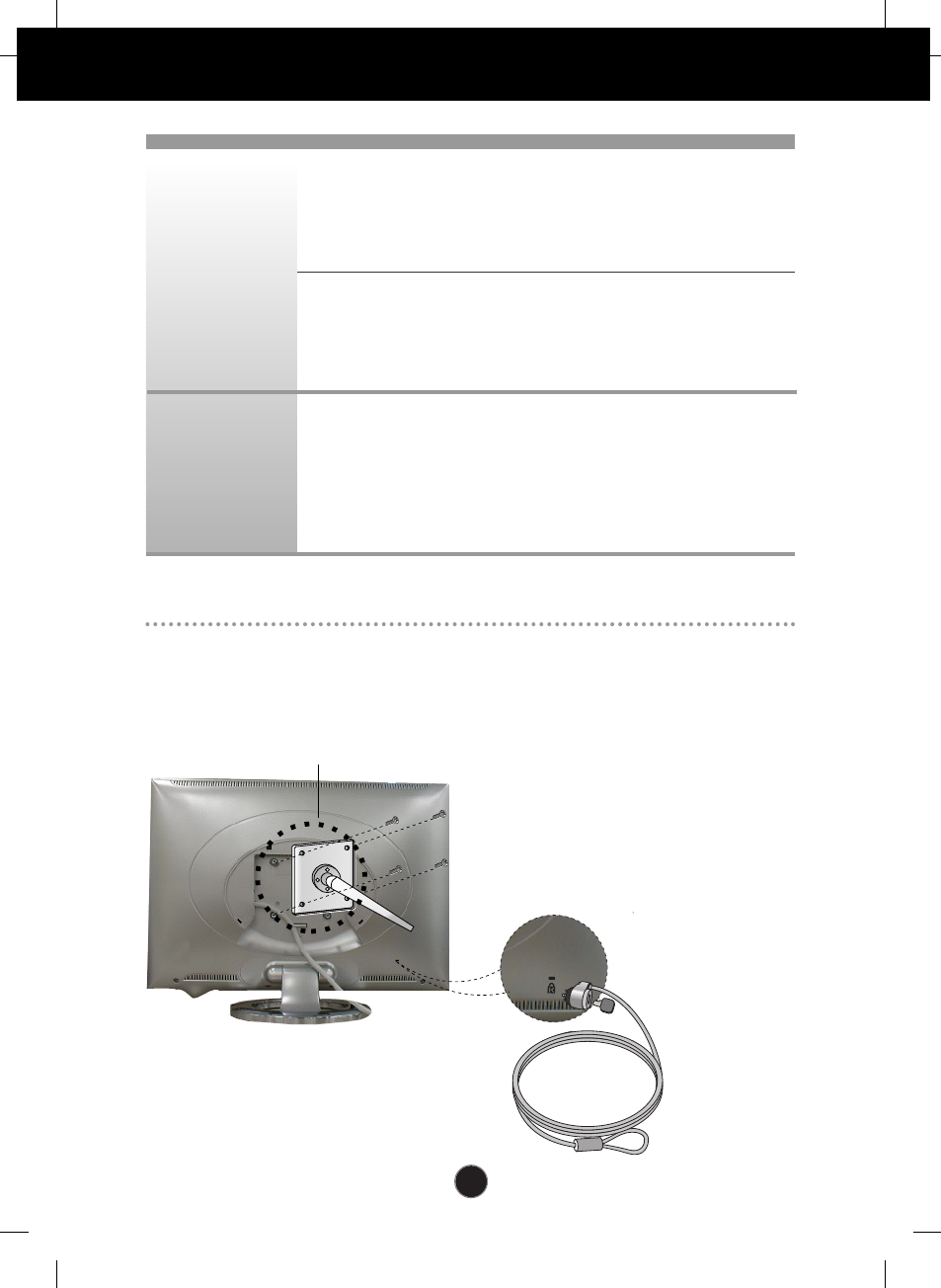
VESA wall mounting
Connected to another object (stand type and wall-
mounted type. This monitor accepts a VESA-
compliant mounting interface pad.- optional)
For further information, refer to the VESA Wall
Mounting Instruction Guide.
Kensington Security Slot- optional
Connected to a locking
cable that can be purchased
separately at most
computer stores

A39
PC mode
Specifications
Display Modes (Resolution) Horizontal Freq. (kHz) Vertical Freq. (Hz)
1
2
3
4
5
6
7
8
9
10
11
640 x 350
640 x 480
640 x 480
720 x 400
800 x 600
800 x 600
832 x 624
1024 x 768
1024 x 768
1280 x 768
1280 x 1024
31.469
31.469
37.500
31.468
37.879
46.875
49.725
48.363
60.123
47.780
63.981
70
60
75
70
60
75
75
60
75
60
60
VGA
VGA
VESA
VGA
VESA
VESA
MAC
VESA
VESA
VESA
VESA
Display Modes (Resolution)
A40
Specifications
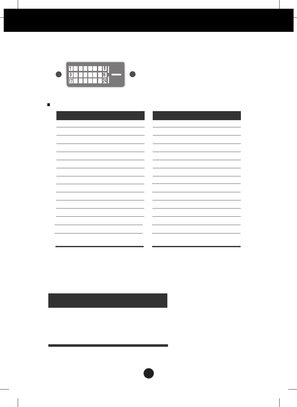
Signal Connector Pin Assignment
Pin Signal
1
2
3
4
5
6
7
8
9
10
11
12
13
14
15
T. M. D. S. Data2-
T. M. D. S. Data2+
T. M. D. S. Data2/4 Shield
T. M. D. S. Data4-
T. M. D. S. Data4+
DDC Clock
DDC Data
Analog Vertical Sync.
T. M. D. S. Data1-
T. M. D. S. Data1+
T. M. D. S. Data1/3 Shield
T. M. D. S. Data3-
T. M. D. S. Data3+
+5V Power
Ground
(return for +5V,
H. Sync. and V. Sync.)
Pin Signal
16
17
18
19
20
21
22
23
24
Hot Plug Detect
T. M. D. S. Data0-
T. M. D. S. Data0+
T. M. D. S. Data0/5 Shield
T. M. D. S. Data5-
T. M. D. S. Data5+
T. M. D. S. Clock Shield
T. M. D. S. Clock+
T. M. D. S. Clock-
T. M. D. S. (Transition Minimized Differential Signaling)
DVI-D Connector
Indicator
Normal
Stand-by/Suspend
DPMS Off
Power switch off
Power cut-off switch off
blue
amber
amber
off
off
blue
dark blue
dark blue
dark blue
off
LED Color
Display Media station
A41
Digitally yours