LG Electronics USA LB563B 15-inch Color LCD Monitor User Manual
LG Electronics USA 15-inch Color LCD Monitor Users Manual
Users Manual

Contents
Introduction ...........................................................A1
Connecting the Monitor.........................................A2
Location and Function of Controls........................A3
Control Panel Function..........................................A4
On Screen Display (OSD) Control Adjustment ....A5
On Screen Display(OSD) Selection
and Adjustment .....................................................A6
Video Memory Modes ...........................................A8
Troubleshooting .....................................................A9
Specifications .......................................................A10
Einleitung................................................................B1
Anschließen............................................................B2
Ort und Funktion der Bedienungselemente ..........B3
Bedienungselemente der Bildkontrolle..................B4
On Screen Display (OSD) Anpassung ...................B5
OSD Einstellung und Auswahlsymbole .................B6
Videospeichermodi ................................................B8
Störungen................................................................B9
Produktbeschreibung...........................................B10
Introduction ...........................................................C1
Branchement du Moniteur ....................................C2
Nomenclature et Fonctions ...................................C3
Fonctions du Paneau de Commande.....................C4
Réglage des Commandes Affichage Écran.............C5
Options de sélection et de Réglage
OSD (affichage écran) ..........................................C6
Mise en Mémoire de Modes Vidéo........................C8
Quelques Conseils en Cas D’incident....................C9
Spécifications D'entree........................................C10
Introduzione ..........................................................D1
Collegamento del Monitor ....................................D2
Posizione e Funzione dei Conando di Controllo ..D3
Funzione del Pannello di Controllo.......................D4
Controllo Regolazione On Screen Display (OSD)
....D5
Elementi di Selezione e Regolazione dell'OSD.....D6
Modalità di Memoria Video..................................D8
In Caso di Problemi ...............................................D9
Specifiche.............................................................D10
Introducción ...........................................................E1
Conectando del Monitor ........................................E2
Ubicacion y Funcion de los Controles...................E3
Función del Panel de Control.................................E4
Ajuste del Control de Exhibición en Pantalla (OSD)
.......E5
Ajuste del OSD y Selección de Elementos.............E6
Modos de Memoria de Video.................................E8
Sugerencias para Localizar las Fallas......................E9
Especificaciones....................................................E10
Introdução...............................................................F1
Conectando o Monitor...........................................F2
Posição dos Controles e Descrição........................F3
Funções do Painel de Controle ..............................F4
Ajuste On Screen Display(OSD)............................F5
Ajustes OSD e Itens de Seleção .............................F6
Modos de Memória de Vídeo.................................F8
Resolvendo Problemas............................................F9
Especificações.......................................................F10
Inleiding .................................................................N1
De Monitor Aansluiten..........................................N2
De plaatsing en de werking van de knoppen........N3
Het bedieningspaneel............................................N4
Bediening via het beeldscherm OSD
(On Screen Display) ..............................................N5
Kiezen en instellen via het OSD-systeem..............N6
Modi voor videogeheugen.....................................N8
Problemen oplossen...............................................N9
Specificaties .........................................................N10
ENGLISH
DEUTSCH
FRANÇAIS
ITALIANO
ESPAÑOL
PORTUGUÊS
NEDERLANDS

A1
Introduction
The FLATRON LCD 563LE/LS Flat Panel Monitor has an active matrix
TFT (Thin-Film Transistor) LCD (Liquid Crystal Display).
This monitor is designed for use in small working areas or for those who need
more working space on the desk.
Features
The FLATRON LCD 563LE/LS is a 15.1-inch (15.1 inches viewable) intelligent
micropro-cessor based monitor.
Digitally controlled auto-scanning is done with the microprocessor for horizontal
scan frequencies between 31 and 61kHz, and vertical scan frequencies
between 56 and 75Hz.
The microprocessor-based digital controls allow you to adjust conveniently a
variety of image controls by using the OSD (On Screen Display).
It supports resolutions up to 1024x768, and has a wide viewing angle of ±60
degrees horizontal and ±45 degrees vertical.
The monitor is shipped with 14 factory pre-programmed video modes that are
permanently resident. In addition, there are 16 user-storable modes, for a total
of 30 memory modes.
Plug and play capability if supported by your system.
This monitor has DDC 2B function.*
Compliant with the following regulated specifications :*
-
EPA ENERGY STAR
-
Swedish TCO’99
ENGLISH
*
For detailed information, please refer to the Reference Guide provided .
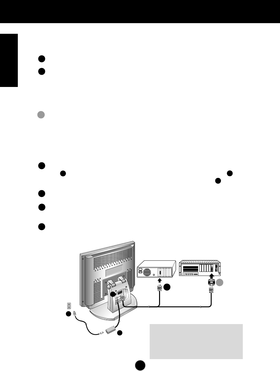
Connecting the Monitor
A2
On the back of the monitor are two plug-in connections; one for the AC
power cord, and the other for the signal cable from the video card.
Power off both the monitor and PC.
Connect the 15 pin VGA connector of the supplied signal cable to the output
VGA video connector on the PC and the matching input connector on the rear
of the monitor. The connectors will mate only one way. If you cannot attach
the cable easily, turn the connector upside down and try again. When mated,
tighten the thumbscrews to secure the connection.
Locate the appropriate MAC to VGA adapter block at your local computer
store. This adapter changes the high density 3 row 15 pin VGA connector to
the correct 15 pin 2 row connection to mate with your MAC. Attach the other
end of the signal cable to the side of the adapter block with 3 rows.
Connect the attached adapter block/signal cable to the video output on your
MAC.
Connect the plug from the AC-DC adapter into the connector on the display
unit. Connect one end of the AC power cord into the AC-DC adapter.
Plug the other end into a properly grounded three-prong AC outlet.
Power on the PC, then the monitor.
If you see the
NO SIGNAL
message, check the signal cable and
connectors.
After using the system, power off the monitor, then the PC.
3
2
1
Power Cord
Signal Cable
D-15P
IBM PC MACINTOSH
D-15P
Mac Adapter
*NOTE : If you see the “OUT OF
RANGE” message, check to make
sure your system is set to one of the
factory preset modes.(see page A8)
1
2
3
3
2
1
4
5
6
2'
2
2'
AC-DC adapter
A3
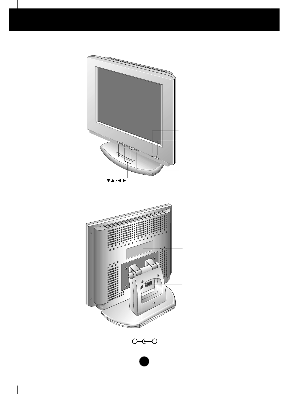
Location and Function of Controls
Rear View
Front View
D-Sub Signal Connecter
Power Indicator
ID Label
Power Button
AUTO/SET Button
Buttons
OSD Button
DC Power Connecter
-+
OSD
AUTO/SET
•••••
•
•
•
•
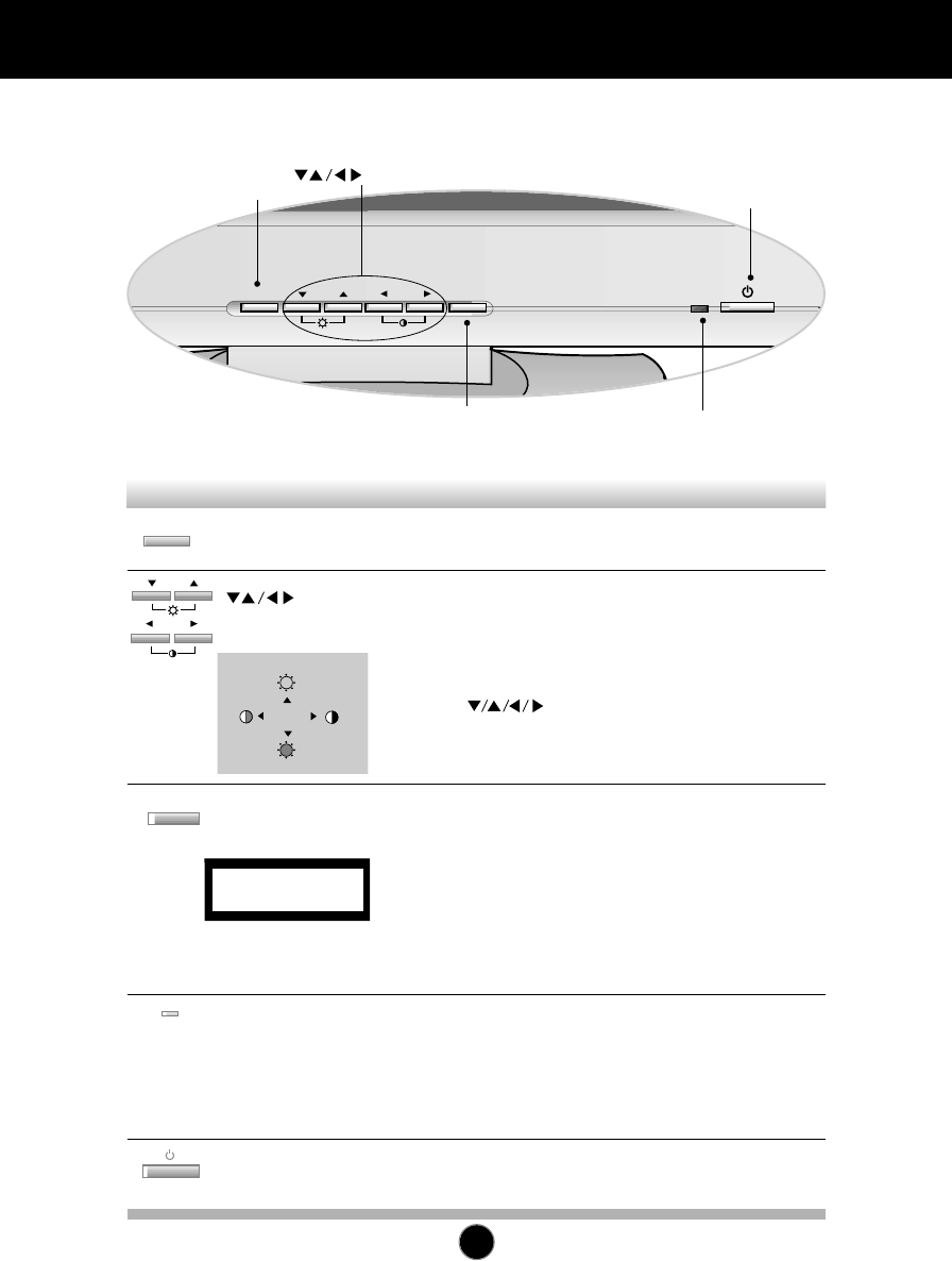
Control Panel Function
A4
Front Panel Controls
OSD
AUTO/SET
Use this button to enter and from the on
screen display (OSD).
Use these buttons to choose or adjust items in
the on screen display.
<Shortcut Keys>
•Brightness and Contrast can be adjusted directly without
entering the On Screen Display (OSD) system. Touch
the buttons to adjust the settings and then
the OSD button to save all changes. The Brightness
and Contrast functions are also available in the On
Screen Display (OSD) menu.
OSD
AUTO/SET
OSD Button
Buttons
This indicator lights up green when the
monitor operates normally. If the monitor is in
DPM (Energy Saving) mode (stand-by/
suspend/power off), this indicator color
changes to amber.
Power (DPMS)
Indicator
Use this button to turn the monitor on or off.Power Button
Use this button to enter a selection in the on
screen display.
* AUTO adjustment function
Touch the AUTO/SET button before using OSD menu.
This button is for the automatic adjustment of the screen
position, clock and phase.
Note: Some signal from some graphics boards may not function
properly. If the results are unsatisfactory, adjust your monitor’s
Position, Clock and Phase manually.
AUTO/SET
Button
Control Function
OSD Button
AUTO/SET Button
Power Button
Power (DPMS) Indicator
Buttons
PROCESSING
AUTO CONFIGURATION
100
100
Making adjustments to the image size, position and operating parameters of
the monitor are quick and easy with the On Screen Display Control system. A
quick example is given below to familiarize you with the use of the controls.
Following section is an outline of the available adjustments and selections you
can make using the OSD.
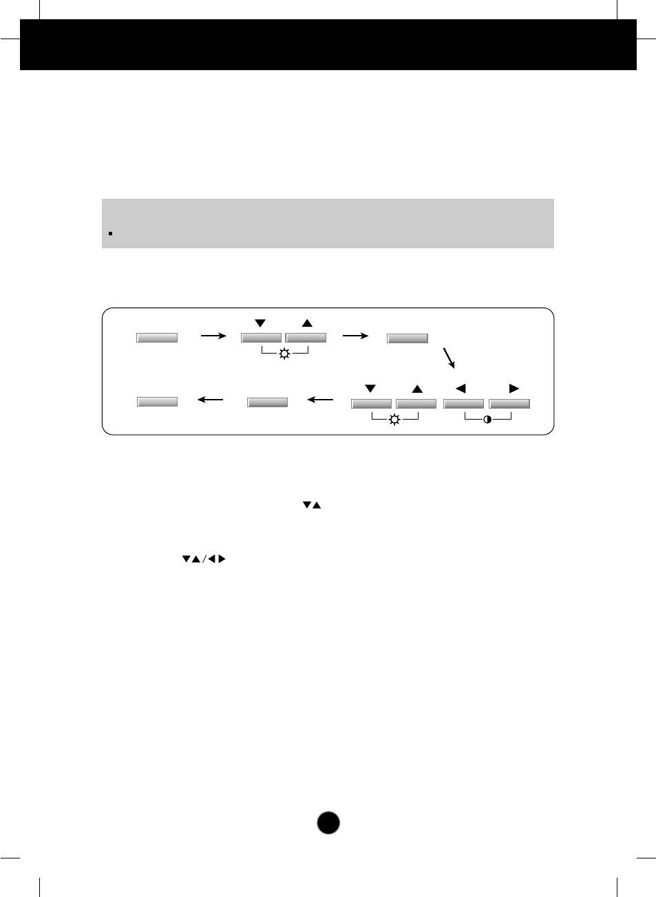
To make adjustments in the On Screen Display, follow these steps:
Press the OSD Button, then the main menu of the OSD appears.
To access a control, use the Buttons. When the icon you want
becomes highlighted, press the AUTO/SET Button.
Use the Buttons to adjust the item to the desired level.
Accept the changes by pressing the AUTO/SET Button.
Exit the OSD by Pressing the OSD Button.
A5
On Screen Display (OSD) Control Adjustment
NOTE
Allow the monitor to stabilize for at least 30 minutes before making image adjustment.
OSD
OSD
AUTO
/
SET
AUTO
/
SET
1
1
2
3
4
5
6
7
1
2
2
3
4
5
6
7
1
2
3
3
4
5
6
7
1
2
3
4
4
5
6
7
1
2
3
4
5
5
6
7
A6
On Screen Display(OSD) Selection and Adjustment
You were introduced to the procedure of selection and adjusting an item
using the OSD system. Listed below are the icons, icon names, and icon
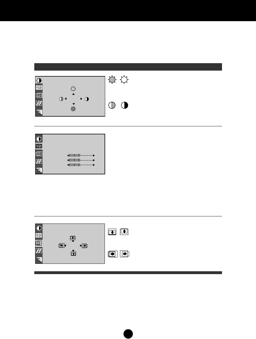
descriptions of the items that are shown on the Menu.
OSD Adjust Description
88
100
BRIGHTNESS CONTRAST
9300K 6500K
COLOR
PRESET
RED
GREEN
BLUE
61
39
POSITION
Brightness
Used to adjust the brightness of the
screen.
Contrast
Adjust the display to the contrast
desired.
PRESET
RED
GREEN
BLUE
9300K/ 6500K
To appear the displays color
temperature.
• 9300K:Slightly bluish white.
• 6500K:Slightly reddish white.
To set your own color levels.
To set your own color levels.
To set your own color levels.
Vertical Position
To move image up and down.
Horizontal Position
To move picture image left and right.
A7
On Screen Display(OSD) Selection and Adjustment
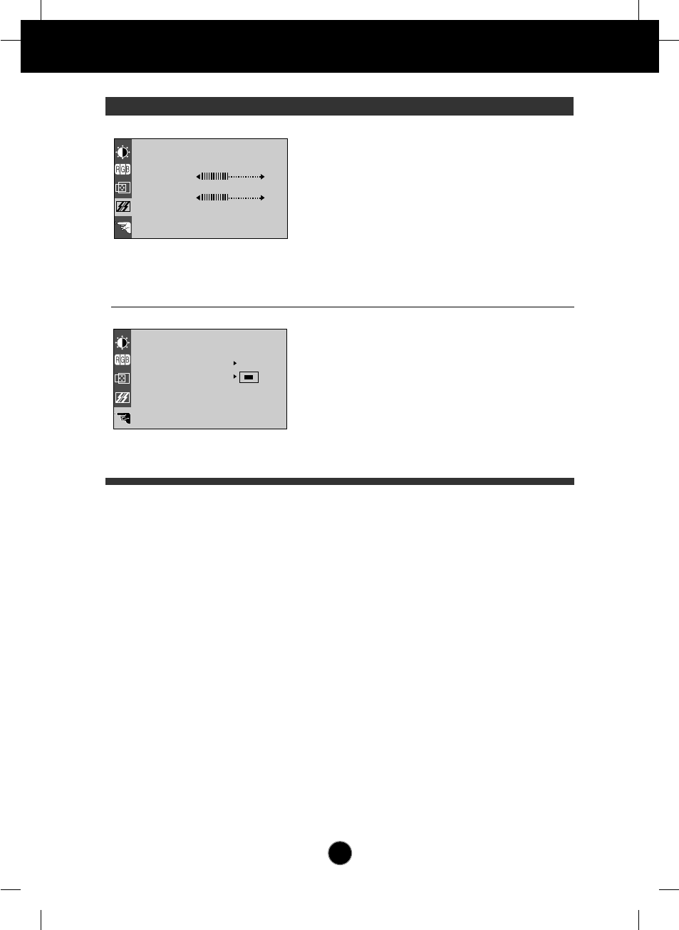
OSD Adjust Description
TRACKING
CLOCK
PHASE
LANGUAGE ENGLISH
OSD POSITION
ELAPSED TIME
48.3kHz / 60.0Hz
PRESET MODE
SETUP
H
0
To minimize any vertical bars or
stripes visible on the screen
background.The horizontal screen
size will also change.
To adjust the focus of the display.
This item allows you to remove any
horizontal noise and clear or sharpen
the image of characters.
To choose the language in which the
control names are displayed.
To adjust position of the OSD window
on the screen.
To display the use time of monitor
LANGUAGE
OSD POSITION
ELAPSED TIME
CLOCK
PHASE

A8
Video Memory Modes
The monitor has 30 memory locations for display modes, 14 of which are
factory preset to popular video modes.
Display Modes (Resolution)
User Modes
Modes 15-30 are empty and can accept new video data. If the monitor detects a
new video mode that has not been present before or is not one of the preset
modes, it stores the new mode automatically in one of the empty modes starting
with mode 15.
If you use up the 16 blank modes and still have more new video modes, the
monitor replaces the information in the user modes starting with mode 15.
1
2
3
4
5
6
7
8
9
10
11
12
13
14
640 x 350
720 x 400
640 x 480
640 x 480
640 x 480
640 x 480
800 x 600
800 x 600
800 x 600
800 x 600
832 x 624
1024 x 768
1024 x 768
1024 x 768
31.47
31.47
31.47
35.00
37.86
37.50
35.16
37.88
48.08
46.88
49.72
48.36
56.48
60.02
70
70
60
67
73
75
56
60
72
75
75
60
70
75
Display Modes (Resolution) Horizontal Freq.(kHz) Vertical Freq.(Hz)
VGA
VGA
VGA
MAC
VESA
VESA
VESA
VESA
VESA
VESA
MAC
VESA
VESA
VESA
Note : This LCD monitor has been pre-adjusted to the video mode of
VESA 1024x768 @75Hz.

A9
Troubleshooting
Check the following before calling for service.
Display Position is incorrect.
Push the AUTO/SET Button.
If the results are unsatisfactory, adjust the image position using the H position
and V position icon in the on screen display.
On the screen background, vertical bars or stripes are visible.
Push the AUTO/SET Button.
If the results are unsatisfactory, decrease the vertical bars or stripes using the
CLOCK icon in the on screen display.
Any horizontal noise appearing in any image or characters are
not clearly portraid.
Push the AUTO/SET Button.
If the results are unsatisfactory, decrease the horizontal bars using the PHASE
icon in the on screen display.
NO SIGNAL message.
The signal cable is not connected, or is loose. Check and secure the
connection.
OUT OF RANGE message appears.
Picture is blank.
The frequency of the signal from the video card is outside the operating range
of the monitor.
Horizontal Frequency: 31kHz-61kHz
Vertical Frequency: 56Hz-75Hz
*Use the graphics board's utility software to change the frequency setting (Refer to the
manual for graphics board).
*You can change the setup to the supported resolution using the Safe Mode (Press the
F8 key during booting the system).
The power LED is illuminated amber.
The monitor is in its display power management mode.
There is no active signal coming from the PC.
The signal cable is not fastened securely.
Check the computer power and graphics adapter configuration.
The monitor doesn't enter the power saving off mode (Amber).
Computer video signal is not VESA DPMS standard. Either the PC or the video
controller card is not using the VESA DPMS power management function.
A10
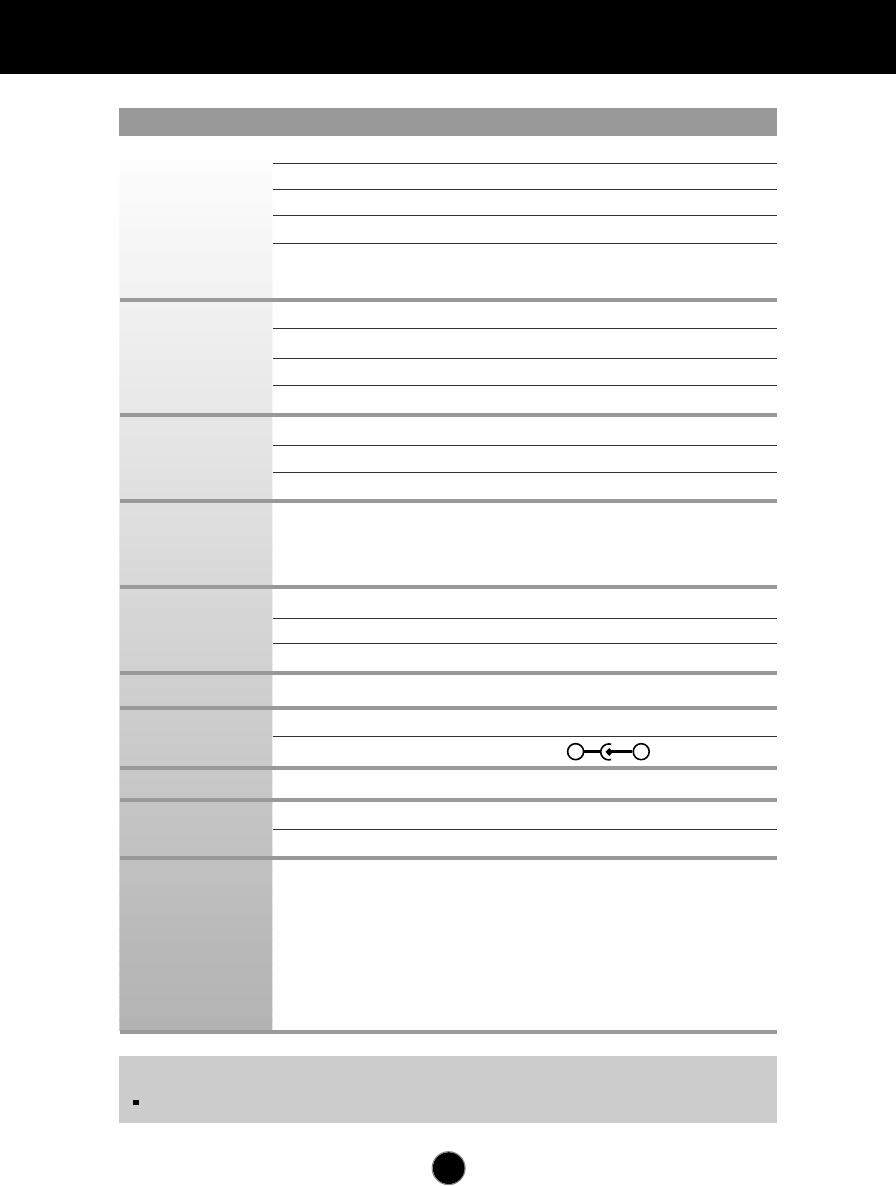
Specifications
Type
15.1inch (38.35cm) Flat Panel Active matrix-TFT LCD,
Anti-Glare coating
Viewable Size 15.1inch (38.35cm)
Pixel pitch 0.3 x 0.3mm
True color FLATRON LCD 563LE : 16, 7 million color
FLATRON LCD 563LS : 262, 144 color
Horizontal Freq. 31 - 61kHz (Automatic)
Vertical Freq. 56 - 75Hz (Automatic)
Input Form Separate TTL, Positive/Negative
Signal Input 15 pin D-Sub Connector
Display Area 307 x 230mm / 12.1 x 9.1inch
Input Form
Separate, RGB Analog, 0.714Vp-p/75ohm, Positive
Resolution VESA 1024 x 768/ 75Hz max
Normal ≤30W
Stand-by/Suspend
≤3W
Power Off ≤3W
Width 38.92 cm / 15.95 inches
Height 36.16 cm / 14.24 inches
Depth 18.24 cm / 7.18 inches
DC 12V 3A
Input AC 100-240V 50-60Hz 1.2A~0.6A
Output DC 12V 1.5A
Net 5.2 kg (11.46 lbs)
Down 5˚
Up 30˚
Operating Condition
Temperature 10 ˚C to 35 ˚C
Humidity 10 % to 80 % non-Condensing
Storage Condition
Temperature -20 ˚C to 60 ˚C
Humidity 5 % to 95 % non-Condensing
NOTE
Information in this document is subject to change without notice.
Display
Sync Input
Video Input
Power
Consumption
Dimensions
Power Input
AC-DC Adapter
Weight
Tilt Range
Environmental
Conditions
-+