LG Electronics USA LGSWFAC73 RF Module User Manual Host Part 2
LG Electronics USA RF Module Host Part 2
Contents
- 1. User Manual
- 2. Host User Manual - Part 1
- 3. Host User Manual - Part 2
Host User Manual - Part 2

ENGLISH
51
INSTALLING CALIBRATION
SOFTWARE ............................ 68
-How to install ......................................................... 68
-How to delete ........................................................68
CONNECTION TYPES ............ 69
X-ray Generator and Detector
Connection of Detector - PC
Mode of connecting Network
-Trigger Cable Instruction .................................70
-Detector and PC(Wired mode) ....................72
-Detector and PC(Wireless mode) ...............75
CALIBRATION SOFTWARE ... 77
-Calibration Software ..........................................77
Settings
Calibration
User BPM
Validation
Exposure Index
-Image Functions ...................................................82
-Log................................................................................84
USAGE.................................... 85
-Launching the Program ....................................85
-Checking IP Address and Ping Test ...........86
-Checking Save Location ...................................87
-Apply ...........................................................................88
-Checking and Changing Detector Settings .
89
-Checking and Changing Calibration
Software Settings................................................90
-Calibration ................................................................ 92
-User BPM .................................................................94
-Validation .................................................................. 96
-EI (Exposure Index) ............................................. 98
-Exit ............................................................................100
-About .......................................................................101
-General PopUp ..................................................102
SERVICE MANUAL ..............104
-Detector Wired IP Address Setting ........ 104
-Wireless AP configuration ...........................106
-Detector Firmware Update .........................108
-Storage of installation date ........................110
-Power Options Setting ..................................111
-Web monitoring ................................................. 112
Internal Information
Web monitoring
MAINTENANCE ...................114
-Cleaning .................................................................. 114
-Inspection ..............................................................114
TROUBLESHOOTING ...........115
SOLUTION FOR FIREWALL
BLOCK ..................................116
SUPPLEMENT. WIRELESS AP
SET UP INSTRUCTION
(MODEL : Cisco Linksys
EA9200) ...............................118
ENGLISH
52
SAFETY INFORMATION
Preparation
•Be sure to connect the cables to the proper connectors. Otherwise, the detector may malfunction or may be
damaged.
•The power supply provided by LG is designed for the detector from LG. Please contact supply, if any other type of
power supply is needed to be used.
•Be sure to fully charge the battery before use. Charge the battery on the day of examination or on the previous day.
•Battery slowly discharges even when not in use. The battery may have expired if it discharges immediately after being
fully charged. You can purchase an optional battery to replace an exhausted one.
•The battery charger provided by LG is designed for the dedicated battery.
•When the detector will not be used for some time, remove the battery.
Handling
•Handle the detector carefully, as it may become damaged if it is hit, dropped, or receives a strong jolt.
•Be sure to use the detector on a flat place so it will not bend. Otherwise, the detector may be damaged.
•Be sure to check the detector daily and confirm that it works properly. Sudden heating of the room in cold areas
will cause condensation to form on the detector. In this case, wait until condensation disappears before performing
exposure. If the detector is used with condensation formed on it, problems may occur in the quality of the detector.
When an air-conditioner is going to be used, be sure to raise/lower the temperature gradually so that a difference
in temperature in the room and in the detector does not occur, to prevent forming of condensation. Follow the
ENGLISH
53
recommended proper Room temp.
•Do not use the detector near devices generating a strong magnetic field. Doing so may produce image noise or
artifacts.
•Keep the connectors free from being in contact with the patient.
•Connectors are intended to be connected to an external device and must follow IEC standards.
•Do not apply excessive weight to the detector. Otherwise, the detector may be damaged.
Overall Pressure: 150kg (330.6lb) over the whole area of detector window.
Partial Pressure: 100kg (220.4lb) on an area 40mm (1.5 inch) in diameter
Disinfection and Cleaning
•Do not spray disinfectants or detergents on the detector.
•When cleaning the detector, be sure to turn off the power, and unplug the power cable from the AC outlet.
•Do not use any flammable chemicals such as thinner, benzene for cleaning. Otherwise, fire or electric shock may
result.
•Wear waterproof gloves to protect your hands from direct contact with disinfectants or detergents.General
Description.

ENGLISH
54
Overview
14HJ701D is wireless Flat Panel Digital X-ray Detector that can generate images of any part of the body, and designed
for a faster approach to digital radiography systems.
This model utilize a combination a amorphous silicon TFT glass and high performance scintillator, along with a pixel
pitch 127um and 3.9lp/mm of resolution, assure sharp and high contrast image quality.
14HJ701D is X-ray imaging acquisition device that is based on flat-panel. This device should be integrated with an
operating PC and a X-ray generator. It can do to utilize as digitalizing X-ray images and transfer for radiography
diagnostic. Data transmission between detector and PC is possible by wire (cable) and wireless (WIFI).
Product Component
•Detector: 14HJ701D
•Control Box : LG Control Box
- AC power cord for Control Box
•Battery Charger : LG Battery Charger
- 2 Battery packs
- AC Power adapter for Charger : 65 W
- AC Power cord for AC Power adapter
•Main Cable
- Detector and Control Box link cable (Supply DC power, Ehternet data, control signals of X-ray generator)
- Trigger Cable (X-ray generator to Control Box, transmit control signal between detector and X-ray generator)
- LAN cable (Control Box to PC, exchanges Ethernet data between PC and detector)
•CD: User’s manual, Calibration Software
•User's manual(book type), Inspection Report

ENGLISH
55
Basic Accessories
255 125
90
Detector 1 EA Charger 1 EA Battery 2 EA
Installation CD 1 EA AC Power adapter 1 EA AC Power cord for Control Box 1EA
AC Power cord for AC Power adapter Control Box 1EA Manual 1 EA
Main cable 1EA Inspection Report 1EA
ENGLISH
56
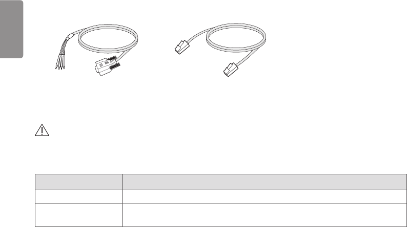
Optional Accessories
Trigger Cable 1EA LAN cable 1EA
•Optional accessories can not be included in accordance with production suffix.
CAUTION
•Need to use the authorized components about the below accessories. Unauthorized components may be cause of the
damage and malfunction of the product.
Component Standard
LAN CABLE More than CAT5E Standard
Power Cord US – Approved Medical grade regulation
Others – Approved country safety regulation
The AC/DC adaptors and etc. except the upper components need to be used only supplied by manufacturer.
ENGLISH
57
PART NAME AND FUNCTION
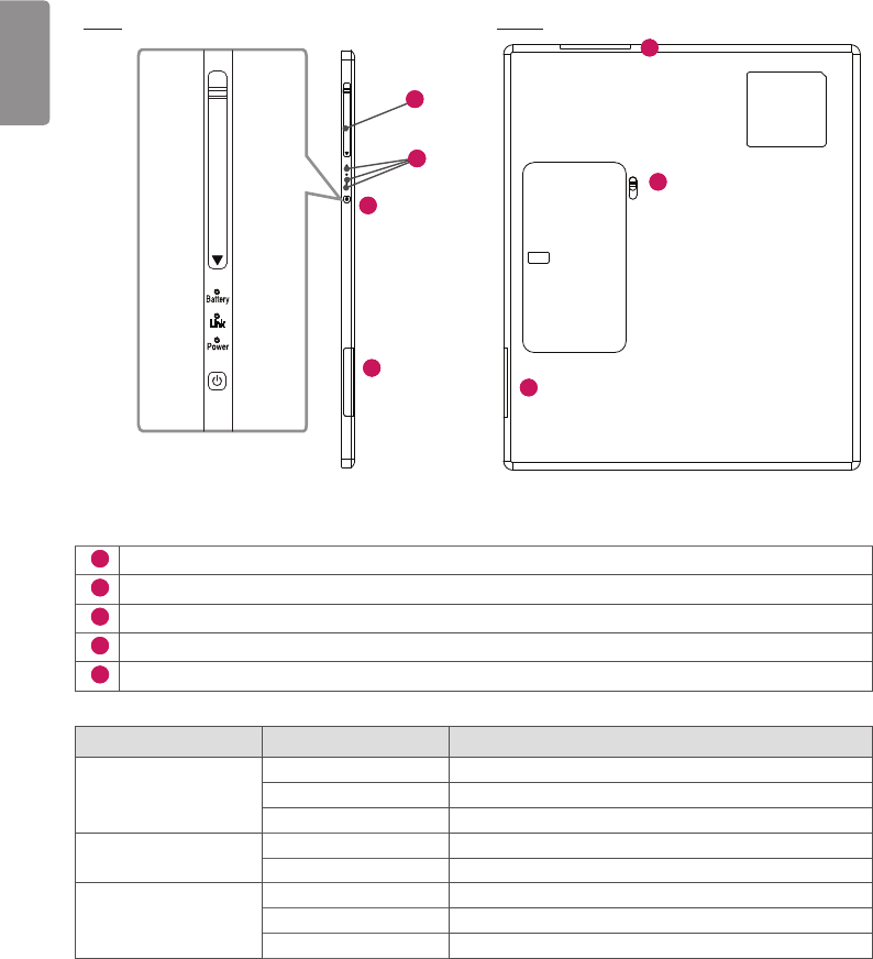
Detector
FRONT
ENGLISH
58
SIDE BACK
1
3
4
5
1
2
1
1
Wireless Antenna
2
Battery Unlock Lever: Unlock lever to remove battery
3
Power Button: Power on/off switch (On : press over 1 sec, Off : press over 5 sec)
4
LED Indicator: Indicating detector’s status
5
Connection to main cable
LED LED Color Status
Battery Green Battery is more than 30% charged.
Orange Battery charging stauts is 10 ~ 30%.
Orange Blinking Battery is less than 10 % charged.
Link Green Ethernet/WIFI connection
Off Ethernet/WIFI no connection
Power Green Power On
Green Blinking Sleep mode
Off Power Off
If there is no communication during "Auto Sleep/Auto Power off" time, Detector will go to Sleep mode/Power off.
This function only works when Detector is not connected with “Detector and Control Box link cable”.
If the Detector receives the communication message during Sleep mode, The Detector will wake up.
User can set the Sleep/Power off times using the Calibration Software.
ENGLISH
59
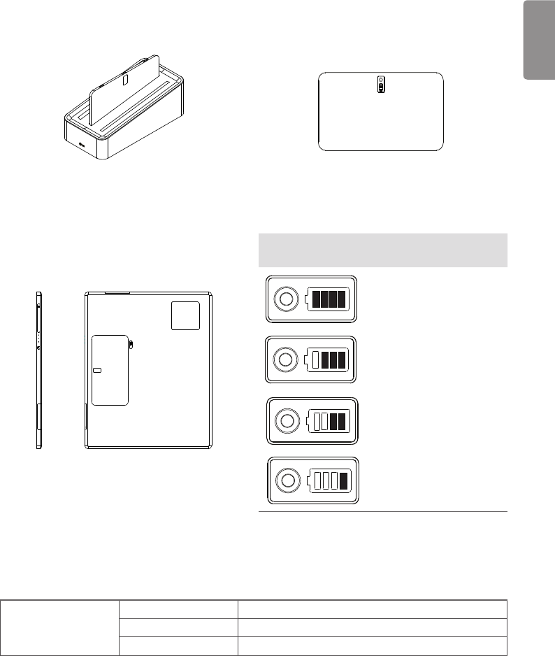
Battery and Charger
1 Battery: Li-ion polymer battery (Charging time - Typ. 4 Hrs)
•Battery pack itself shows the remaining battery percentage.
Battery Remain
Indicator Battery Level
75 ~ 100%
50 ~ 75%
25 ~ 50%
0 ~ 25%
2 Battery charger: 3 ports cradle type
3 LED Indicator: Following LEDs are located to each battery - 3 batteries.
LED Green Completion of charging
Orange On charging
Orange Blinking Error (Connection error, etc)
ENGLISH
60
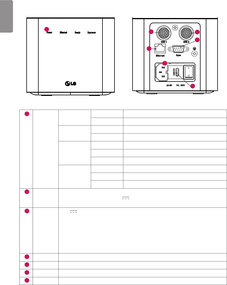
Control Box
255
109.8
125
1
255
109.8
125
7
5
2 3
6
4
1
LED POWER Green Power normal operation
Off Power off (AC power cord no connection or Power error.)
Ethernet Green Ethernet normal operation
Off Ethernet disconnected.
Ready Green Ready signal from X-ray generator is active.
Off Ready signal from X-ray generator is inactive.
Orange blink Error
Exposure Orange Exposure signal from X-ray generator is active.
Off Exposure signal from X-ray generator is inactive.
Orange blink Error
2
DXD 1 Connecting the Control Box and the detector A.
This connector supply power (24 V 2.1 A) to the detector, transmits X-ray
synchronization signals and Ethernet image data.
3
DXD 2 24 V 2.1 A, Trigger signals, Ethernet data for Detector B
Control Box supports 2 Detector connection.
Usage is, one is for bucky stand, the other is for table(bed).
Generally, X-ray room of hospital installs 2 detectors, bucky stand and table type, it's for more
convinient and efficient working environment.
These 2 detectors are not operated simutaniously, control box selects the operating detector
by AWS command.
4
AC-IN Connects AC power cord
5
Ethernet Ethernet port to transmit image/command between the detector and PC.
6
Sync This is to synchronize the detector and X-ray generator.
7
Fuse T4L 250V
ENGLISH
61
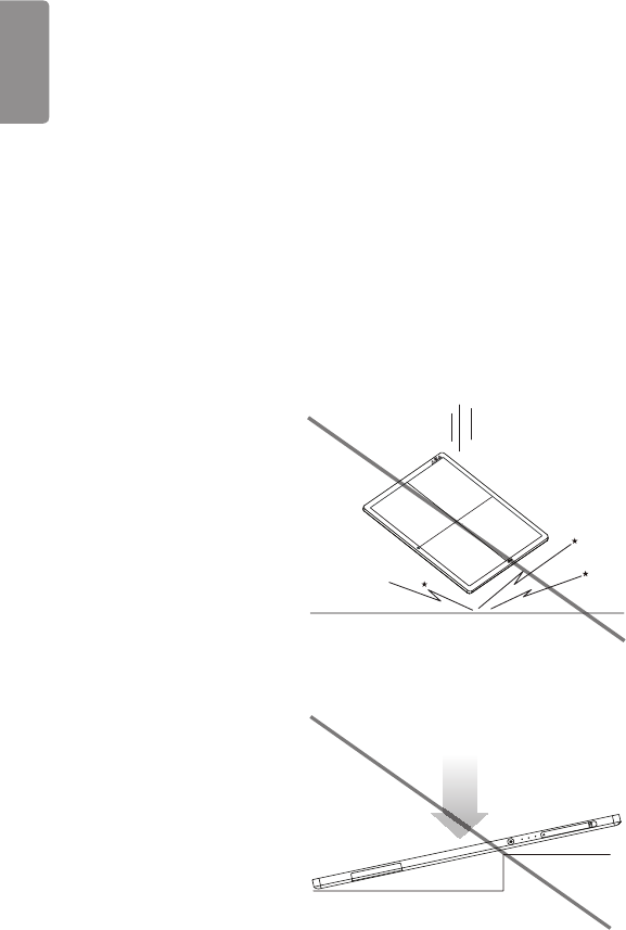
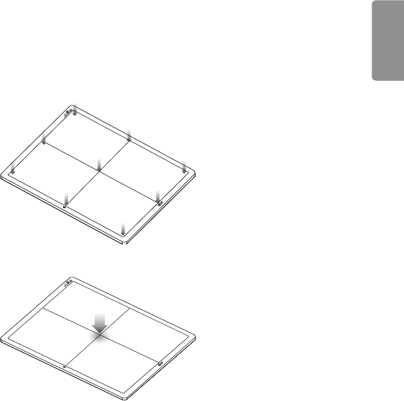
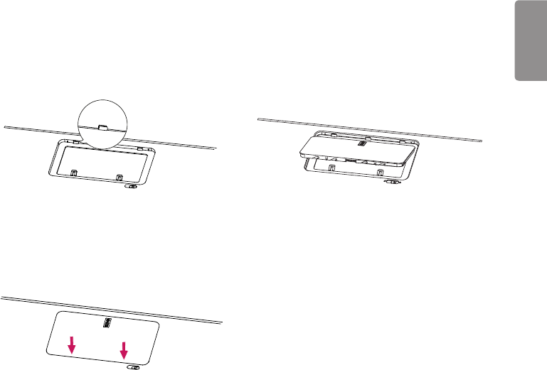
BATTERY INSTALLATION
1 Check the battery mounting hole direction. 2 Insert into the hole on the side with the indicator.
3 Press the opposite side to secure the battery
indicator.

ENGLISH
62
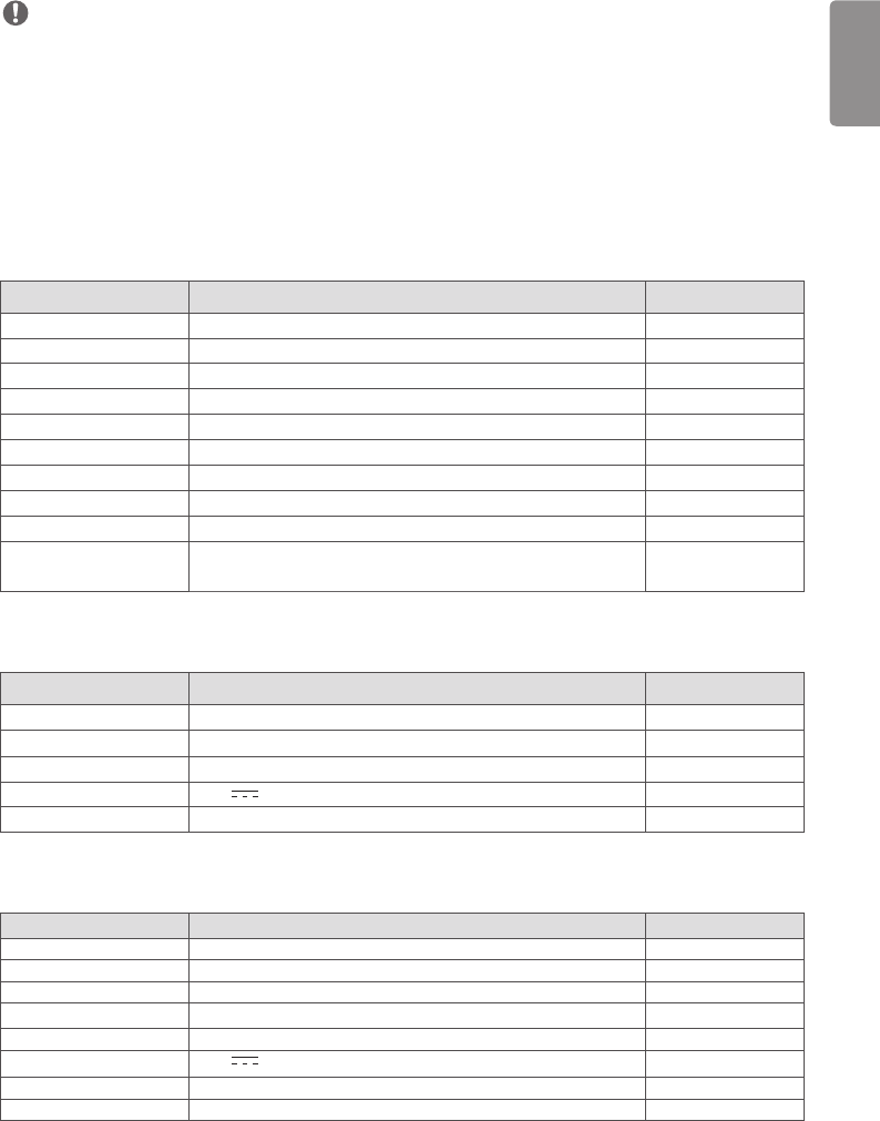
SPECIFICATION OF EACH PART
The product specifications are subject to change without prior notice for product improvements.
“ ~ ” refers to alternating current (AC), “ ” refers to direct current (DC).
Detector
Item Specification Units
Model 14HJ701D
Sensor type Amorphous Silicon with TFT
Scintillator Type CsI:TI
Total Pixel Matrix 3328 x 2816 Pixels
Total Pixel Area 422.655 (16.63) x 357.632 (14.08) mm (inch)
Pixel Pitch 127 um
Effective Pixel Matrix 3323 x 2751 pixels
A/D Conversion 16 bits
Data Transfer 802.11 a/g/n/ac Wireless LAN, typ. 200Mbps with 802.11ac
Gigabit Ethernet typ. 500Mbps
Preview time 2 sec
Energy range 40 ~ 150 kVp
MTF Typ. 85%, min. 70% at 0.5 lp/mm %
DQE Typ. 63%, min. 50% at 0.1 lp/mm %
Defective lines Less than 20 Lines
Defective pixels Less than 9630 Pixels
Dimension 384.0 x 459.5 x 15.0 (15.1 x 18.0 x 0.5) mm (inch)
Weight Typ. 2.95 (6.5) kg (lb)
Window material Carbon Fiber
Trigger mode Manual Mode
Auto Mode (Auto Exposure Detection)
Power consumption Typ. 26 (Charging & Operating)
Typ. 16 (Operating only – no charging)
Typ. 7 (Standby only – no charging)
W
Wireless Standard:
802.11 a/g/n/ac compliance
Peak mode: 866 Mbps
Frequency: 2.4 GHz / 5 GHz
Bandwidth: 20 MHz / 40 MHz / 80 MHz
MIMO: 2X2
Rating 24 V 2.1 A, 7.5 V 3850 mAh (Battary: LBQ7222L)
Applied part Type : BF Type, Location : Front of Detector (only for effective area)
ENGLISH
63
NOTE
•Maximum wireless signal rate derived from IEEE standard specifications. Actual data throughput will vary. Network
conditions and environmental factors, including volume of network traffic, building materials and construction, and
network overhead, lower actual data throughput rate.
•Recommended Maximum operable distance: 2 m (From the Access Point)
•Wireless antennas: The module adopts the latest 802.11ac technology. The transmitter of the module is powered by
host equipment (Detector). The antennas are 2 printed-dipole antennas.
•Wireless module: 802.11 a/b/g/n/ac USB2.0 module is implemented. It supports 2T2R (2 transmit 2 receive) MIMO
technology, which delivers throughput up to 300 Mbps.
Battery
Item Specification Units
Model LBQ7222L
Rating 7.5 V, 3850 mAh, 30 Wh
Size 204.1 x 10.5 x 7.8 (8.0 x 0.4 x 0.3) mm (inch)
Weight Typ. 240 (0.5) g (ib)
Output Norminal voltage 7.5 VDC
Cycle time Max. 800 Cycles
Operation Temp 10 - 35 ℃
Charging time Typ. 4 Hours
Capacity Typ. 4000 mAh
Battery performance 1400 shots acquired for 3.2 hours
(cycle time 8s , without sleep , with Full charged battery)
Images
Battery Charger
Item Specification Units
Model LG Battery Charger
Size 125 x 255.0 x 90.0 (4.9 x 10.0 x 3.5) mm (inch)
Weight Typ. 900 (1.9) g (ib)
Input 19 V 3.42 A
Output Norminal voltage 8.7 VDC
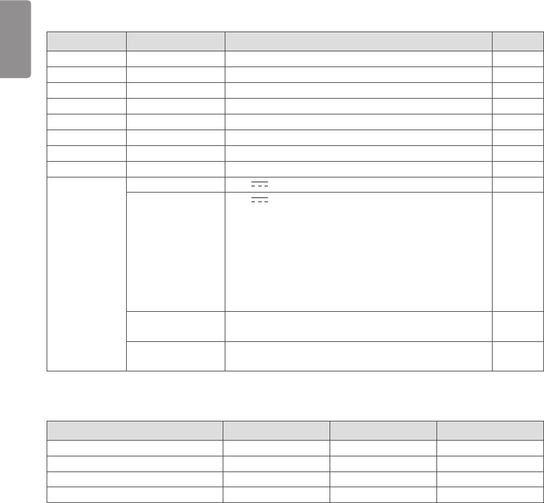
Battery Charger Adapter
Item Spec Units
Model DA-65J19
Manufacturer Asian Power Devices Inc. (APD)
Size 134.0 x 59.8 x 31 (5.2 x 2.3 x 1.2) mm (inch)
Weight Typ. 335 g (ib)
Input 100-240 V ~, 50-60 Hz, 1.5-0.7 A
Output 19 V 3.42 A
Class I
Cable length 1500 (59) mm (inch)
ENGLISH
64
Control Box
mm (inch) Desc. Specification Units
Model LG Control Box LG Control Box
Size 125.0 x 255.0 x 109.8 (4.9 x 10.0 x 4.3) mm (inch)
Weight Typ. 1.3 (2.86) kg (Ib)
Input AC Power 100-240 V ~, 50/60 Hz, 1.4-0.7 A
AC Inlet Fuse 1 T4L 250V
AC Inlet Fuse 2 T4L 250V
Power Fuse 1 (F101) T 3.15AH 250V
Power Fuse 2 (F102) T 3.15AH 250V
Output DXD 1 24 V 2.1 A, Trigger signals, Ethernet data for Detector A
DXD 2 24 V 2.1 A, Trigger signals, Ethernet data for Detector B
Control Box supports 2 Detector connection.
Usage is, one is for bucky stand, the other is for table(bed).
Generally, X-ray room of hospital installs 2 detectors, bucky
stand and table type, it's for more convinient and efficient
working environment.
These 2 detectors are not operated simutaniously, control box
selects the operating detector by AWS command.
Ethernet Transmission image/command between the detector and PC
Sync Transmission control signals between the detector and X-ray
generator
Cables
Item Length Unit Qty
Main cable 1 (39.3) m (inch) 1
LAN cable (optional) 10 (393.7) m (inch) 1
Power cord (110 V or 220 V) 1.5 (59.0) m (inch) 2
Trigger cable (Optional) 15 (590.5) m (inch) 1
ENGLISH
65
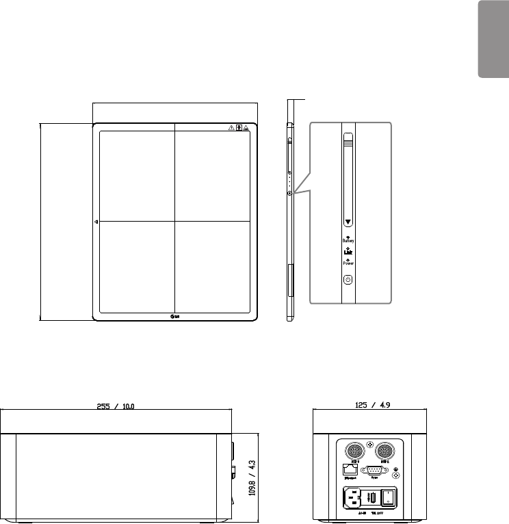
DIMENSION (UNIT: mm/inch)
Detector
384 / 15.1
459.5 / 18.0
15 / 0.5
Control Box
255 / 10.0
109.8 / 4.3
125 / 4.9
ENGLISH
66
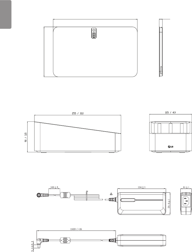
Battery
204.6 / 8.0
110.5 / 4.3
7.8 / 0.3
Battery Charger
255 / 10.0 125 / 4.9
90 / 3.5
Battery Charger Adapter
Ⰼ
ম
ম
ম
Ⰼ
ম
ENGLISH
67
ENVIRONMENTAL REQUIREMENT
PC system requirement
PC Specification
CPU intel i5
Memory 4 GB
Disk capacity At least 10 GB, 500 GB recommended
Network card dual ethernet 100/1000 bps
OS Windows 7/8.1/10(32bit, 64bit)
Monitor Min. Resolution 1280x720
AP Cisco model is recommended(ex : Linksys EA9200)
etc
Environmental Requirements
Item Min. Typ Max. (%) Units
Temperature (Storage) -20 60 ℃
Temperature (Operation) 10 35 ℃
Humidity (Storage) 85 Non-condensing, Relative
Humidity
Humidity (Operation) 80
Pressure (Storage) 50 106 kPa
Pressure (Operation) 70 106 kPa

ENGLISH
68
INSTALLING CALIBRATION SOFTWARE
How to install
Run the calibration software installation file. Once the installation file has been executed, follow the installation
instructions on the screen.
How to delete
You can delete the Calibration Software in the following ways:
Deleting from the Control Panel
1 Select Control Panel from the Start menu.
2 Select Programs and Features in Control Panel.
3 Select the LG DXD Calibration on the lists.
4 When the program installation and deletion screen appears on the screen, select the Delete button.
5 Follow the deletion instructions on the screen and click the Next button to proceed.
Deleting with the installation file
1 Run the calibration software installation file, then follow the deletion instructions on the screen.
NOTE
•When using the installation file to delete the program, the installation file must be the same version as the current
software.

ENGLISH
69
CONNECTION TYPES
X-ray Generator and Detector
Select Trigger Mode in accordance with the acquisition method.
- Auto Mode : Detector detects the image obtained after the X-ray
- Manaul Mode : Detector acquires image by pressing generator exposure switch
Connection of Detector - PC
The connection mode used between the detector and PC.
- Wired Mode: Uses the Control Box to connect the detector to a PC.
- Wireless Mode: Uses a wireless AP to connect the detector to a PC.
Mode of connecting Network
Wired or wireless modes are set automatically depending on whether or not the main cable is connected when the
detector is turned on.
1 If the main cable is connected when the power is turned on: Wired mode
2 If the main cable is not connected when the power is turned on: Wireless mode
3 If the cable is disconnected while in wired mode: Switches to wireless mode
4 If the cable is connected while in wireless mode: Maintains wireless mode (charging)
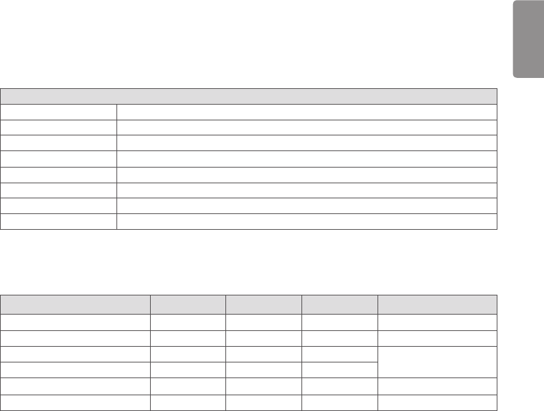
Mode Generator - Detector Detector - PC
Case 1 Auto Mode Wired Mode
Case 2 Auto Mode Wireless Mode
Case 3 Manual Mode Wired Mode
Case 4 Manual Mode Wireless Mode
ENGLISH
70
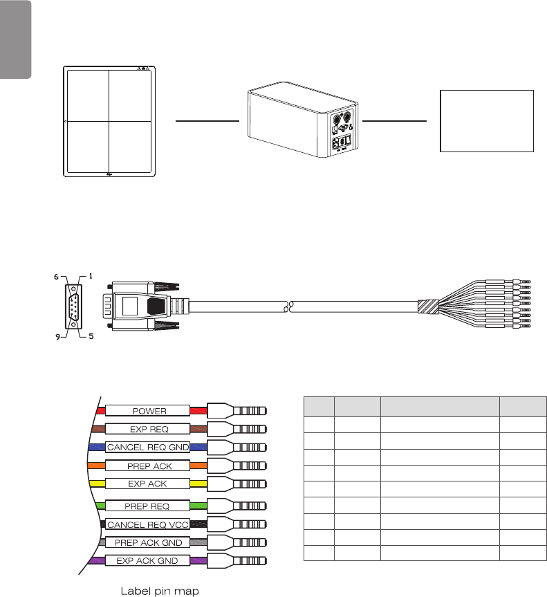
Trigger Cable Instruction
Generator
•Connects a Trigger cable to Port A of the Control Box when there is X-ray generator interface.
No. COLOR Description
1 RED POWER Use
2 BRN EXP REQ Use
3 BLU CANCEL REQ GND NC
4 ORG PREP ACK NC
5YEL EXP ACK Use
6 GRN PREP REQ Use
7 BOK CANCEL REQ VCC NC
8 GRY PREP ACK GND NC
9 VIO EXP ACK GND Use
ENGLISH
71
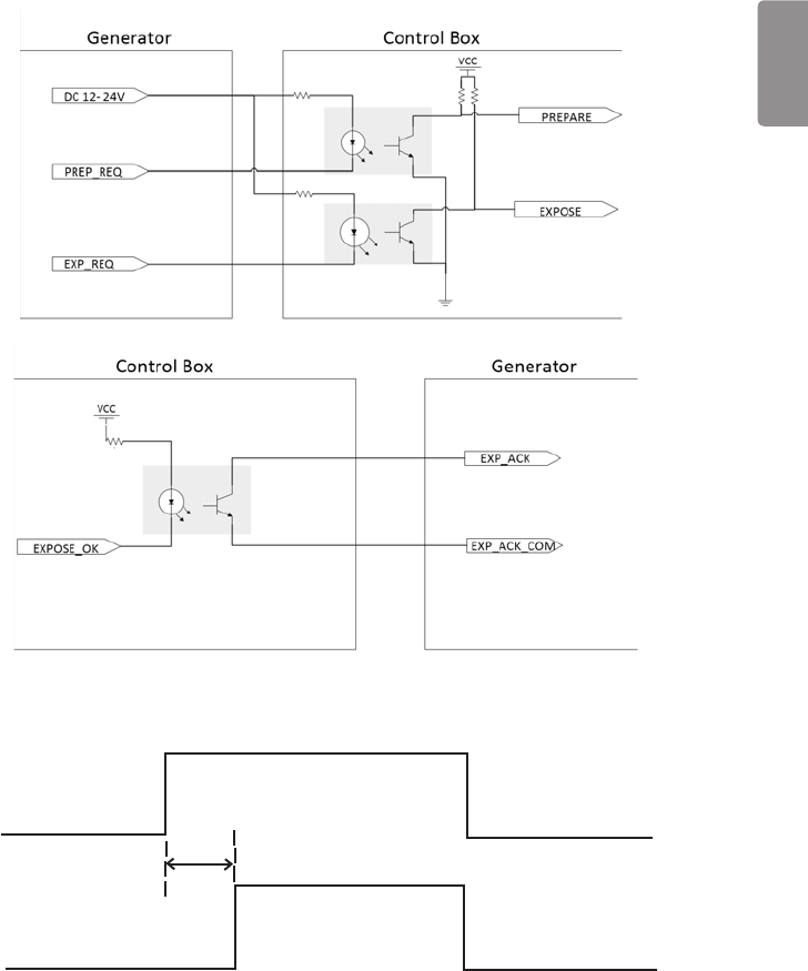
-
<Assembly Diagram>
EXP_REQ
EXP_ACK
<Timing Chart>
ENGLISH
72
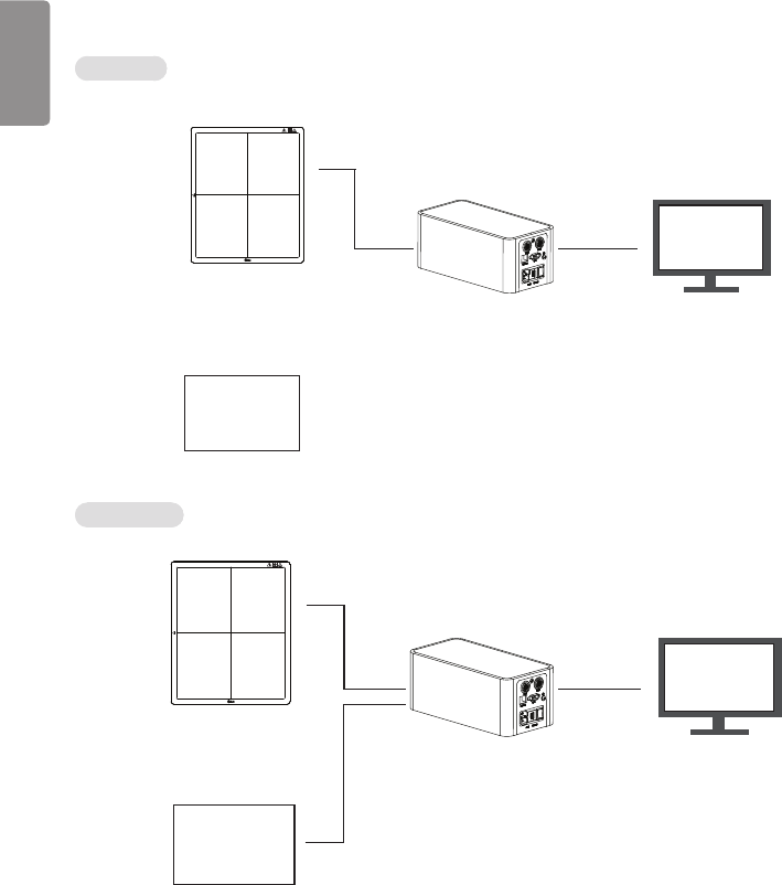
Detector and PC(Wired mode)
Auto Mode
Generator
PC
Detector
Main Cable
LAN cable
Manual Mode
Generator
PC
Detector
Main Cable
LAN cable
Trigger Cable
ENGLISH
73
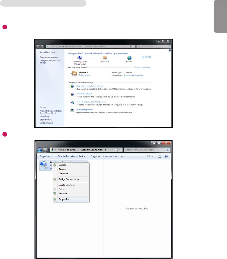
MAKING CONNECTIONS - Wired Connection
1 Connect the PC to the control box using a LAN cable. Connect the detector to the control box using a link cable.
2 Configure the PC settings as below:
1
Open the Network and Sharing Center.
- (Control Panel > Network and Internet > Network and Sharing Center)
2
Right-click on Local Area Connection and enter Properties.
ENGLISH
74
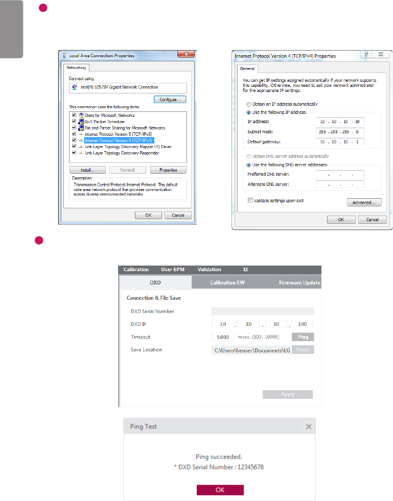
3
Select Internet Protocol Version 4 (TCP/IPv4), then enter Properties to set the following IP address.
- IP address: 10.10.10.2 to 10.10.10.254 (Set it to an IP address other than 10.10.10.100.)
- Subnet mask: 255.255.255.0
- Gateway: 10.10.10.1
4
Run the LG DXD Calibration. Go to Settings > DXD > Connection&File Save, enter Detector IP (10.10.10.100),
then run the Ping to check the connection.
ENGLISH
75
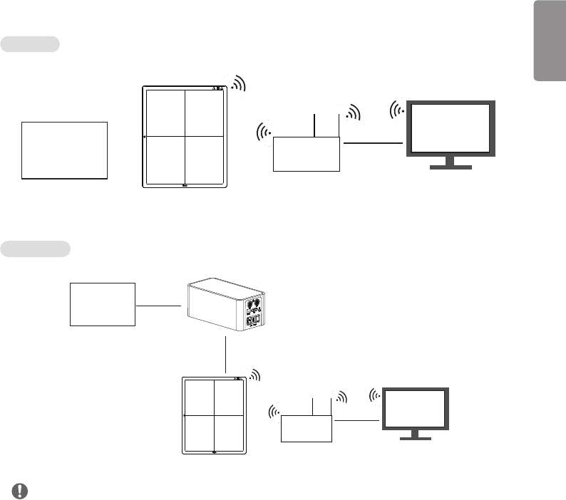
Detector and PC(Wireless mode)
Auto Mode
Detector
Generator
PC
AP LAN cable
Manual Mode
Detector
Generator
PC
AP LAN cable
Trigger Cable
Main Cable
NOTE
Please install the AP and Detector as near as possible without obstacles in between them.

ENGLISH
76
MAKING CONNECTIONS-Wireless Connection
1 The Default Wireless Settings as below.
- SSID : LGEDXD
- Password : lgedxd2000
2 It is possible to change the Wireless Settings using LG DXD Calibration Software.
•Please see the Service manual (Wireless AP configuration) for details.
3 Please reboot the Detector after removing the main cable on Detector.
(If the main cable is disconnected when the power is turned on: Wireless mode)
4 PC settings and connection with Detector are same with wired Connection.
Please refer to the "MAKING CONNECTIONS - Wired Connection".
•Tip : Refer to Wireless AP Set Up Guide
- "Supplement. Wireless AP Set Up Instruction
(Model : Cisco Linksys EA9200)"
ENGLISH
77
CALIBRATION SOFTWARE
To ensure that optimal image quality is obtained from the detector, the detector must be calibrated. The Calibration
Software generates and verifies the values necessary for calibration.
NOTE
•To ensure optimal image quality, you should calibrate every month for the first three months after the purchase and
half-yearly calibration thereafter.
•It is recommended that you leave the detector on for five minutes before calibrating.
Calibration Software
The features of the Calibration Software include Settings, Calibration, User BPM, Validation and Exposure Index.
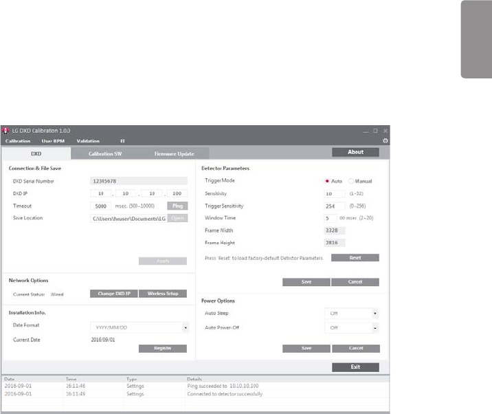
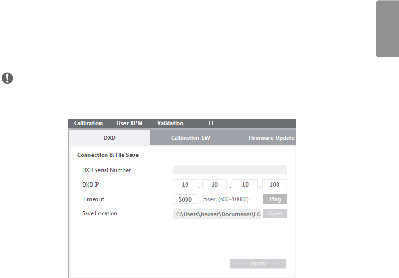
Settings
Settings include DXD settings, Calibration SW settings and Firmware Update.
•DXD: Configures the settings required to obtain calibration images and detector settings.
<Settings Screen: Detector>
ENGLISH
78
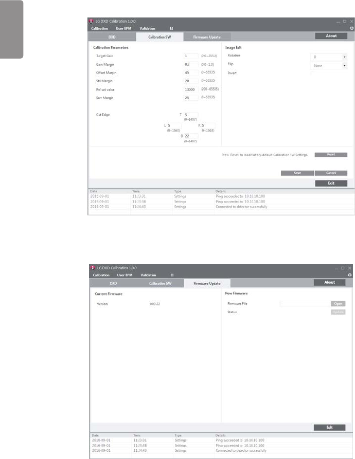
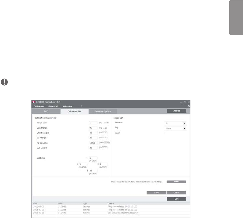
•Calibration SW: Configures the settings required for to calibrate software algorithms.
<Settings Screen: Calibration SW>
•Firmware Update: Checks the firmware version of the detector or performs the firmware update.
<Settings Screen: Firmware Update>
ENGLISH
79
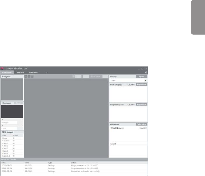
Calibration
Calibration involves the following procedures:
•Dark and Bright images are obtained from the detector.
- Dark Image: An image obtained without generating X-rays.
- Bright Image: An image obtained by generating X-rays without a phantom or any other object on the detector.
•Generate Avgdark, Offset, and Gain: Used for Corrected Image calculations.
- Corrected Image: An image generated by applying calibration results to a raw image.
•Generate Bad Pixel Map: Bad pixel values are calibrated using surrounding pixel values.
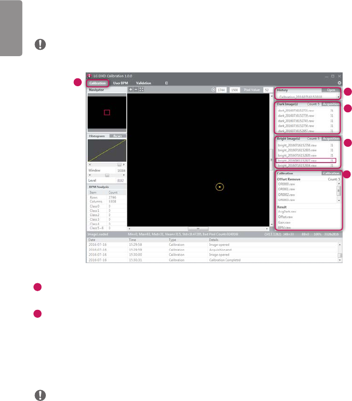
<Calibration Screen>
ENGLISH
80
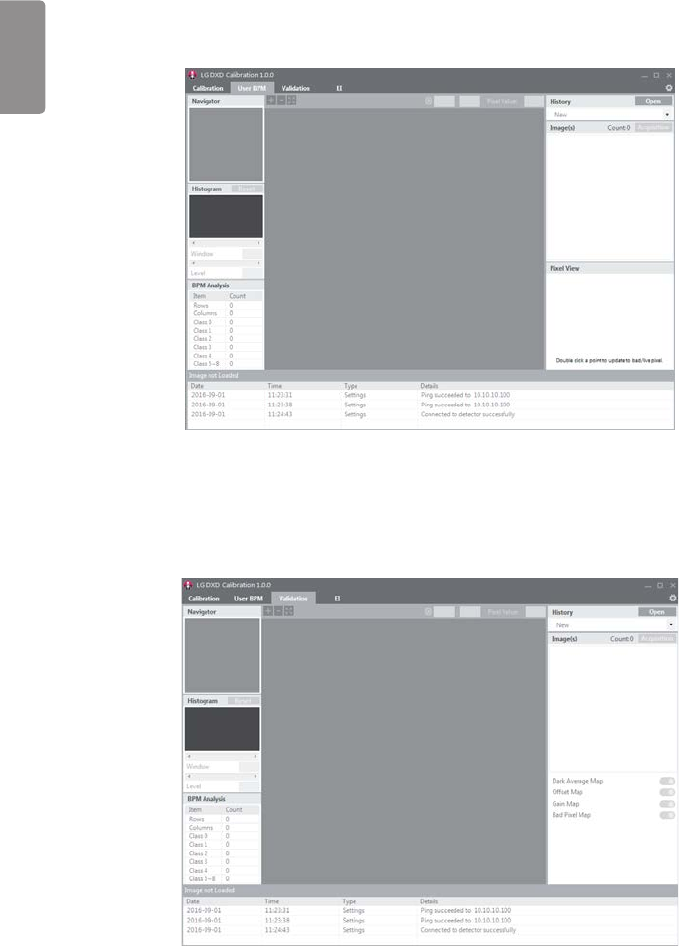
User BPM
This is used to assign additional bad pixels in BPM.raw after calibrating.
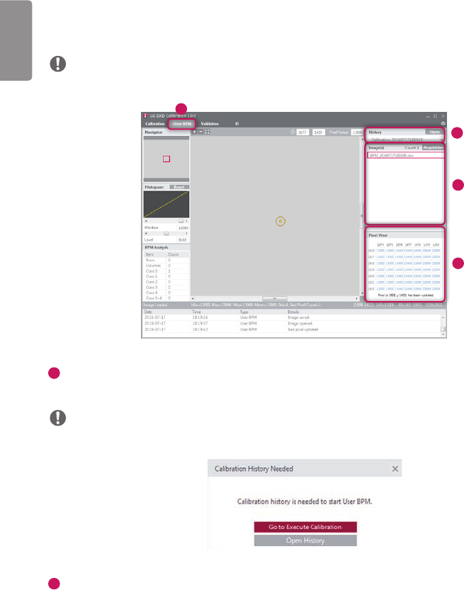
<User BPM Screen>
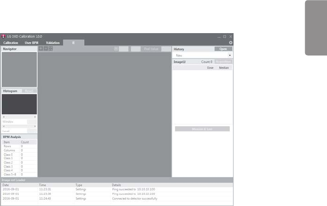
Validation
This is used to validate the final image by applying calibration results to the X-ray image.
<Validation Screen>
ENGLISH
81
Exposure Index
This calculates and saves median output value per input dose as a linear expression and a table.
<Exposure Index Screen>
ENGLISH
82
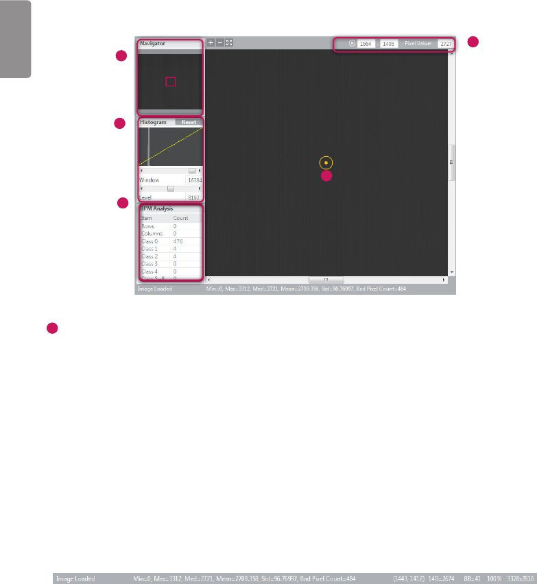
Image Functions
5
3
2
4
1
1
Image Viewer
•The Calibration, User BPM, Validation, and EI menus include an image viewer that lets you view the acquired images.
•An image is loaded and displayed when it is acquired or clicked.
•Information about the image is displayed in the following sections.
- Image Loaded: Indicates whether an image is loaded in the image area.
* When an image is loaded: Image Loaded.
* When no image is loaded: Image not Loaded.
- Min: Minimum pixel value within the image area.
- Max: Maximum pixel value within the image area.
- Med: Median value of the image.
- Mean: Mean value of the image.
- Std: Standard deviation value of the image.
- Bad Pixel Count: Bad pixel count in the image area.
- 14B = N, 8B = M: Representation of the pixel value at (x,y) in bits.
- Bad Pixel Count: Bad pixel count in the image area.
- 100%: Percentage of the image shown in the image area compared to the entire image size.
- (X x Y): Size of the entire image.

ENGLISH
83
2
Navigator
•The Navigator shows the entire area of the acquired image and indicates the zoomed in/out area.
•The red rectangle in the Navigator indicates the area shown in the Image Viewer.
•Clicking a position in the Navigator moves the red rectangle to the position and displays the area in the Image Viewer.
3
Histogram
•Histogram of the acquired image is shown here.
•Window/Level can be adjusted for better image distinction.
•Use the <> buttons or the scroll bars below the Histogram graph to adjust window/level.
•Click the Reset button to restore the default values.
4
Reference Point
•When you click a position inside the Image Viewer, a reference point is specified, and the coordinates and pixel value
of the reference point are shown at the top. You can also move the reference point by entering the X and Y values
manually.
- Since reference point coordinates are numbers, only numeric values can be entered.
5
Bad Pixel Map Analysis
•Displays the results of bad line and bad pixel class analysis based on the Bad Pixel Map after calibration.
ENGLISH
84
Log
This shows the necessary information about the application execution process that is helpful to the user.
It consists of the date, time, type and content, which are saved as a log file.
ENGLISH
85
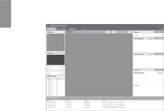
USAGE
Launching the Program
•Double-click the executable file installed on your PC to launch the calibration software.
•If launching for the first time, the Settings screen appears.
ENGLISH
86
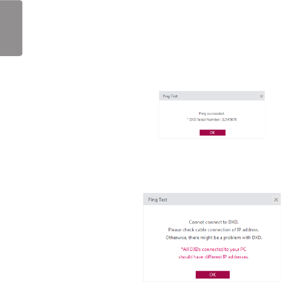
Checking IP Address and Ping Test
•A default IP address is entered for the detector.
•If you change the IP address of the detector, enter the new detector IP address in the detector IP field of the
calibration tool.
•For instructions on changing the detector IP address, see "Detector and PC(Wired mode)".
•After entering the IP address, set a timeout value and click the Ping button to perform a ping test. A pop-up message
appears if the ping test is successful.
•The following pop-up window appears if the ping test is unsuccessful. If the pop-up window appears, check your PC's
network settings, the connection between the detector and PC, the detector status, the Control Box status and the
IP address, then perform the ping test again.
ENGLISH
87
Checking Save Location
While the calibration software is run, the acquired images, logs, result files and factory-default calibration
results are saved in the designated location.
You can change the storage path in the Save location.
Click the Apply button when a folder is created in the specified path.
NOTE
•Default: C:\Users\heuser\Documents\LG DXD Calibration
•heuser: User name
ENGLISH
88
Apply
After performing the ping test and verifying the save location, click the Apply button to perform the following
procedures
1 Automatically create the necessary folders in the save location designated in the Checking Save Location stage.
2 Load from the detector and save the factory-default calibration results.
3 Load the detector's settings.
Dark Im-
ages
Automatic creation of
the Serial Number folder
(Created when Apply is
complete)
Condition: Created if
the same Serial Number
folder is not found in the
custom folder
Creation of date/time folder
(created when the Calibration
button is clicked)
Avgdark.raw
Gain.raw
Offset.raw
BPM.raw
EI results
(A folder is created for the date/time
applied at the time of EI.)
History file
Log Shows logfile including connections +
bpm class
Image Bright Images
Dark Images
User BPM images
Validation images
EI images
Raw images
Factory calibration
(Created when Apply is
complete if the folder or files
do not exist or if the files are
abnormally small)
Avgdark.raw
Gain.raw
Offset.raw
BPM.raw
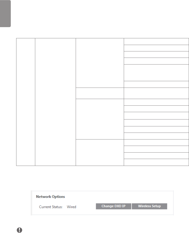
4 When Apply is successful, the detector's network status is displayed.
Current Status : Wired Connection.
Wireless Connection.
NOTE
•Other menus remain inaccessible until you perform Apply. (Calibration, User BPM, Validation, EI)
ENGLISH
89
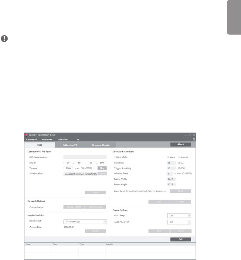
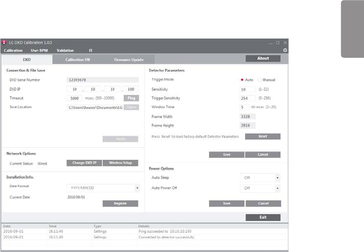
Checking and Changing Detector Settings
Upon Apply, the current detector settings are loaded on the settings screen below.
•Detector Parameters are parameters used when obtaining images from the detector.
•Click the Save button to apply the settings entered.
•Descriptions of the data are as follows:
- Trigger Mode : This sets Trigger Mode.
* Auto : Enables the Auto Exposure Detection feature.
* Manual : Disables the Auto Exposure Detection feature.
- Sensitivity : This is the panel sensitivity.
- Trigger Sensitivity : This is the threshold at which the detector starts acquiring images.
- Gain : This is the gain value to be saved in the Detector.
- Frame Width/Height : This is the detector size.
- Window Time : This sets the time taken to read the values after the x-ray exposure. (An input value of 5 means
500 ms.)
•Descriptions of the buttons are as follows.
- Save : Applies the changes.
- Reset : Loads the factory default settings.
- Cancel : Loads the last saved values.
ENGLISH
90
Checking and Changing Calibration Software Settings
The calibration parameters are updated when the Calibration Software tab is clicked.
Calibration Parameters
These settings are used to perform calibration.
•Descriptions of the data are as follows:
- Target Gain : Amplification level within algorithms.
Pixels with values that exceed the Gain Margin are specified as bad pixels.
- Offset Margin : Offset margin value used within algorithms.
- Std Margin : Pixels with values that exceed the Std Margin are specified as bad pixels.
- Ref Sat Value : Maximum range of values during Image acquisition.
- Surr Margin : In corrected bright images, if the difference between the standard pixel value and surrounding pixel
value exceeds the Surr Margin, the standard pixel is specified as a bad pixel.
- Cut Edge : This indicates the pixel values to cut off in the top, bottom, left or right directions of the frame. After
acquiring an image in Validation or EI, the border of the image to cut off is indicated as dotted lines in
the Image Viewer.
ENGLISH
91
Image Edit
These are Image Viewer settings of the selected tool.
• Rotation : This sets the rotation angle of the image. (0°, 90°,180°, 270°)
• Flip : Sets how the image shown in the Image Viewer is rotated. (None, Horizontal, Vertical)
• Invert : Inverts the image data shown in the Image Viewer.
• Click the Save button to apply the settings entered.
•Descriptions of the buttons are as follows.
- Save : Applies the changes.
- Reset : Loads the factory default settings.
- Cancel : Loads the last saved values.
- Exit : Return to the previous screen.
NOTE
•The next stage will not be accessible until you perform Apply.
ENGLISH
92
Calibration
After configuring all settings, click the Calibration tab to open the Calibration menu.
NOTE
•This tab cannot be accessed until the settings have been configured.
1
5
2
3
4
1
Open Calibration Menu
- Click the Calibration menu button to open the menu.
2
Get Dark
The menu is used to acquire dark images necessary for performing calibration.
- When a dark image is acquired, the image count increases and the image file is saved in the Image folder within the
location specified in Settings.
- After acquiring an image, the mean value of the image is shown next to the file name.
- After comparing multiple images, you can delete any abnormal images by right-clicking them.
- When deleted, both the list entry and the file are deleted.
NOTE
•All the images are deleted when calibration ends. For backup, copy the images and paste them into another folder.
•Up to 10 images can be saved.
•Dark Image: An image obtained without generating X-rays.
ENGLISH
93
3
Get Bright
The menu is used to acquire bright images necessary for performing calibration.
- When a bright image is acquired, the image count increases and the image file is saved in the Image folder within
the location specified in Settings.
- After acquiring an image, the mean value of the image is shown next to the file name.
- After comparing multiple images, you can delete any abnormal images by right-clicking them.
- When deleted, both the list entry and the file are deleted.
NOTE
•All the images are deleted when calibration ends. For backup, copy the images and paste them into another folder.
•Up to 10 images can be saved.
•Bright Image: An image obtained by generating X-rays without a phantom or any other object on the detector.
4
Calibration
This area is used for calibration.
•At least four dark images and four bright images are required for calibration.
•Calibration result files are saved in a folder that is created based on the date and time of the calibration.
•The BPM Analysis is updated when the calibration is complete.
NOTE
•When calibration is performed more than five times, the oldest results are automatically replaced with new results.
•For backup, copy the results folder and paste the results into another folder.
5
History
- You can load previous calibration results. Click the Open button to load the previous calibration result files.
NOTE
•Selecting any one of the files also loads other associated files. (Select any one of the Avgdark, Offset, Gain or BPM
files, and all the four associated files will be loaded.)
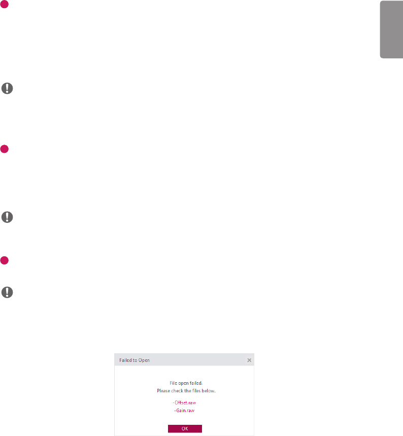
•If there is a problem while loading the files, the following error popup window appears. If the popup window below
appears, check the file sizes, path, file names and folder access permissions, and then try again.
ENGLISH
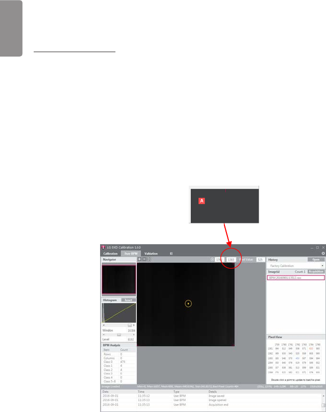
94
User BPM
The user can manually edit the Bad Pixel Map created during Calibration in this menu.
NOTE
•You can skip the User BPM stage and proceed to Validation.
2
4
3
1
1
Open User BPM Menu
- Click the User BPM menu button to open the menu.
NOTE
•The pop-up window below will appear if you open this menu without performing calibration.
2
Check History File
- Check that the History name created during calibration matches the name shown in the current History window.
- The User BPM procedure is performed by applying the selected History.
ENGLISH
95
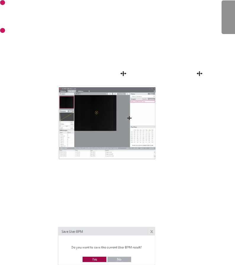
3
Image Acquisition
- User BPM requires image acquisition as it involves a visual inspection of images with applied calibration results.
When the Acquisition button is clicked and a bright image is acquired, the name of the image will appear in the
image list.
4
Pixel View
•Check pixel values in Pixel View
- Pixel values for the center of the Image Viewer are displayed in the Pixel View window.
- The minimum value, maximum value and pixels estimated as bad pixels are shown as below.
* Minimum value : Indicated as a green number
* Maximum value : Indicated as a red number
* Estimated bad pixels : Indicated with gray background
- The size of the Pixel View window can be adjusted using the icon. The mouse pointer changes to a icon
when hovering over the border between the Pixel View and Image Viewer.
•Mark additional bad pixels in Pixel View
- Double-click a pixel in Pixel View to mark it as a bad pixel. Double-click a bad pixel again to unmark it.
- As you mark bad pixels, the values in Bad Pixel Analysis are updated in real time.
- Also, pixels marked as bad pixels are replaced with calibrated pixel values.
•Saving Final User BPM
- The result file is saved when a different menu is opened.
- When you attempt to exit the current menu and open another menu, a popup window appears asking whether
you want to save the data.
- Select Save to add a calibration history entry and save an updated version of the BPM.raw file.
ENGLISH
96
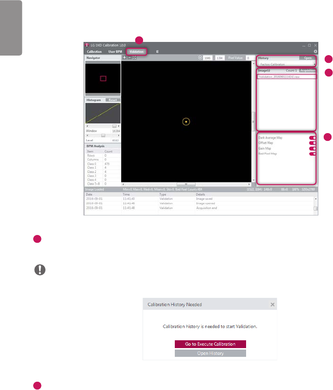
Validation
This procedure allows you to perform a visual inspection of the calibration results after completing calibration.
1
2
3
4
1
Open Validation Menu
- Click the Validation menu button to open the menu.
NOTE
•The pop-up window below will appear if you open this menu without performing calibration.
2
Check History File
- Please confirm whether the name of the History file created during calibration matches the name displayed in the
History window.

ENGLISH
97
3
Image Acquisition (Procedure matches that from the User BPM stage)
- When the Acquisition button is clicked and a bright image is acquired, the name of the image will appear in the
image list.
- Information about the image is displayed below the Image Viewer.
4
Apply/Unapply Calibration Results
- You can apply/unapply calibration results (Dark Average Map, Offset Map, Gain Map, Bad Pixel Map) to the
acquired image.
: Apply
: Unapply
NOTE
•When an image is acquired and loaded for the first time, all results are applied by default.
•If no image has been acquired, the Apply/Unapply button is disabled.
ENGLISH
98
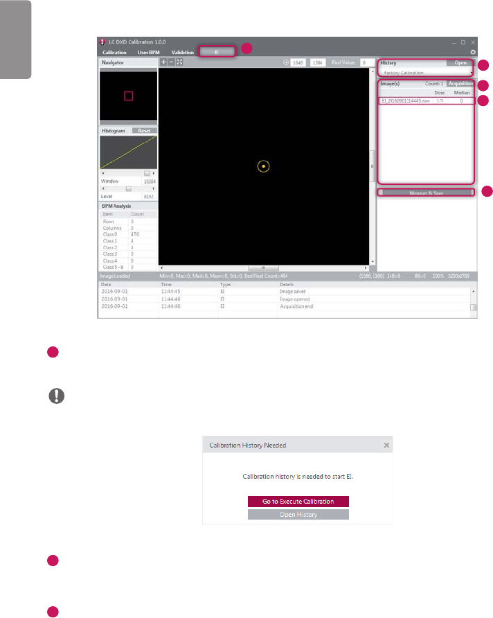
EI (Exposure Index)
1
2
3
4
5
1
Open EI Menu
- Click the EI menu button to open the menu.
NOTE
•The pop-up window below will appear if you open this menu without performing calibration.
2
Check History File
- Please confirm whether the name of the History file created during calibration matches the name displayed in the
History window.
3
Image Acquisition (same as User BPM and Validation)
- When the Acquisition button is clicked and a bright image is acquired, the name of the image will appear in the
image list.
- Information about the image is displayed below the Image Viewer.
ENGLISH
99
4
Enter Dose Value
- Enter an X-ray dose in the dose input field. (Unit: uGy)
- The EI value is calculated based on the input value.
- Because the dose value is a number, only numeric values can be entered. Non-number values cannot be entered
automatically.
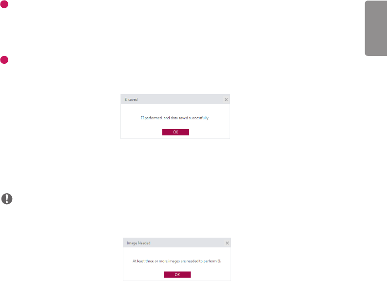
5
Measure & Save
- When you click the Measure & Save button after acquiring an image and entering a dose value, the popup
notification below appears.
- The results are saved in the save location specified for EI calculation.
(Example: C:\Users\heuser\Documents\LG DXD Calibration\Serial Number\Calibration Results Folder (Time and Date)
heuser: Username)
NOTE
•When Measure & Save is repeated, the results file in the folder is updated.
•The following pop-up window appears if the minimum number of images required (three) is not met.
ENGLISH
100
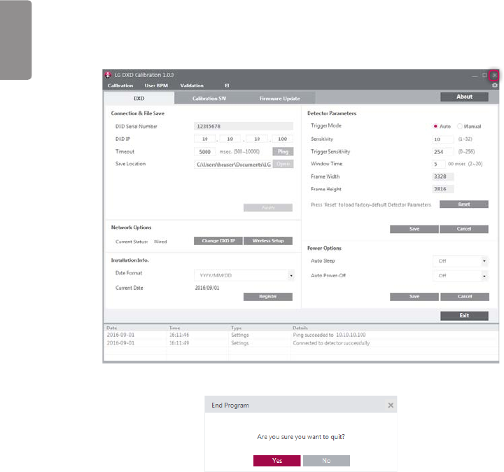
Exit
When you click the Quit button, the calibration tool quit popup window appears.
In the popup window below, click the Yes button to quit or click the No button to return to the previous screen.
<Settings: Exit>
<Exit>
ENGLISH
101
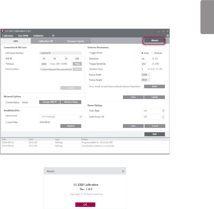
About
When you click the About button in Settings, the following popup window appears.
It shows the information about the application.
<Settings: About>
<About>
ENGLISH
102
General PopUp
The following are descriptions of the general pop-up windows that may appear when the calibration software is being
used.
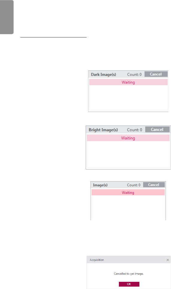
Image Acquisition Cancellation
•When the Acquisition button is clicked for image Acquisition, it will be replaced with a Cancel button while the
image is being acquired.
•Once image acquisition is complete, the button will revert to an Acquisition button.
•During image acquisition, you can cancel the process by clicking the Cancel button.
<Get Dark Image Cancel Button: Available in Calibration>
<Get Bright Image Cancel Button: Available in Calibration>
<Get Image Cancel Button: Available in User BPM, Validation, EI>
•The popup window below appears when the cancellation is complete.
<Get Image Cancel Complete Popup Window>

ENGLISH
103
Image Acquisition Failure
•The popup window below appears when image acquisition fails. Check the network and Detector status, then try
again.
<Image Acquisition Failure Popup Window>
ENGLISH
104
SERVICE MANUAL
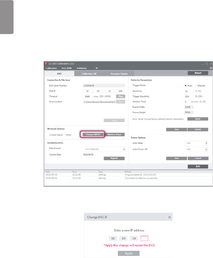
Detector Wired IP Address Setting
1 From the Usage section, perform "Launching the Program", "Checking IP Address and Ping Test", "Checking Save
Location" and "Apply".
2 Click the Change DXD IP button.
3 At the popup window, change the setting and click the Apply button.
- When the Apply button is clicked, the system attempts to change the IP address.

ENGLISH
105
4 Check the result and restart the detector.
- The following popup windows appear, depending on the successful and failed.
<Popup Window for Successful Configuration>
- Once the new IP address is applied, restart the detector so that the new setting takes effect.
- Restart the detector automatically using the program.
- Because the detector is disconnected when restarting, perform the Connection & File Save process again.
ENGLISH
106
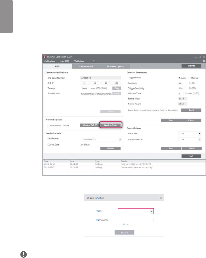
Wireless AP configuration
To have the Detector connect wirelessly to an AP, the AP information must be saved in the Detector in advance.
Once the AP information is transferred and saved in the Detector, the Detector attempts to connect to the AP.
The saved AP information can be viewed in the Web Monitoring feature.
1 From the Usage section, perform "Launching the Program", "Checking IP Address and Ping Test", "Checking Save
Location" and "Apply".
2 After checking that wireless settings are enabled on the PC, click the Wireless Setup button.
- If a pop-up appears, enter your SSID and password, then click Apply.
NOTE
SSID can be appear garbled or as question marks or boxes and others because of encording or compatibility.
ENGLISH
107
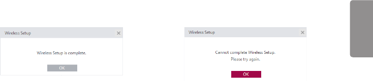
3 Check results.
- The following popup windows appear, depending on the result.
<Popup Window for Successful Configuration> <Popup Window for Failed Configuration>
ENGLISH
108
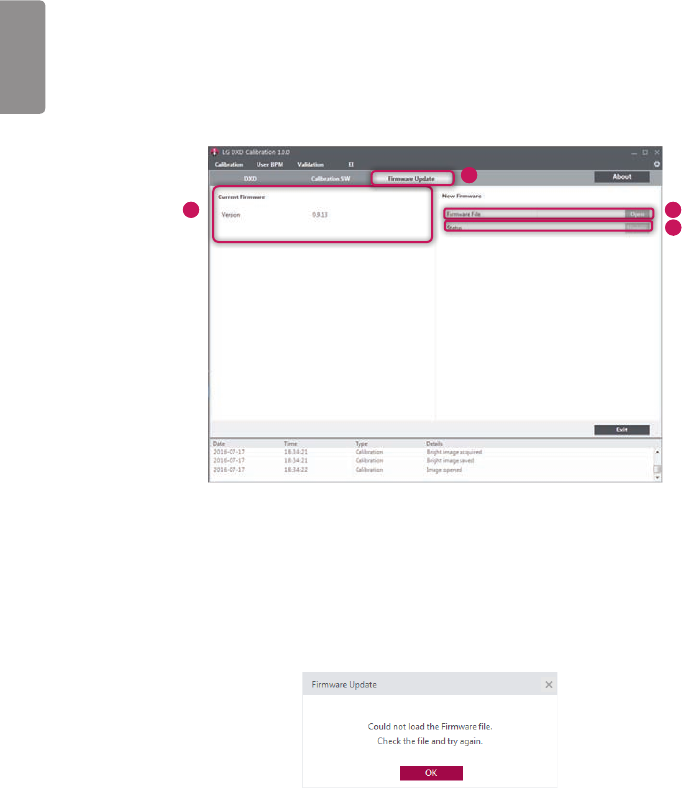
Detector Firmware Update
This menu allows you to check the firmware version of the detector or update the firmware.
1 From the Usage section, perform "Launching the Program", "Checking IP Address and Ping Test", "Checking Save
Location" and "Apply".
2 Select the Firmware Update tab.
2
4
3 5
3 Check the current firmware version.
- The current firmware version of the detector is shown here when the PC is connected to the detector.
4 Select a firmware file to update.
- Click the Open button to open a file browser window. When you select a file to update, the system validates the
file.
- If the file is correct, the file name appears in the Firmware File section.
- If the file is invalid, the following popup window appears.
<Popup Window for File Loading Failure>
ENGLISH
109
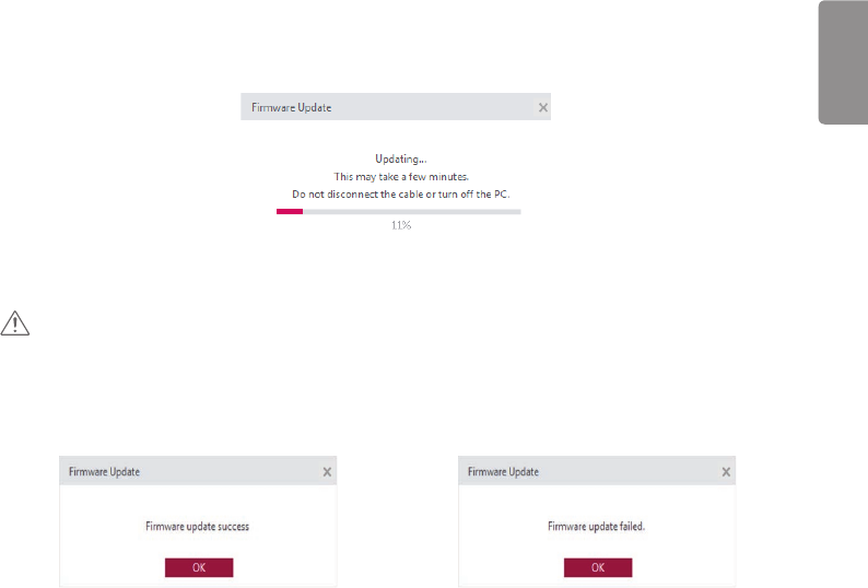
5 Perform the update.
- Select a file, then click the Update button to start the Update process.
- The progress status is shown in the Status field.
<File Updating Popup Window>
CAUTION
•Do not remove the power cable until the update is complete. The update may not be successful if the power is
disconnected during the update process.
6 Check results.
- When the update is complete, the result is shown in a popup window.
<File Update Successful Popup Window> <File Update Failed Popup Window>
ENGLISH
110
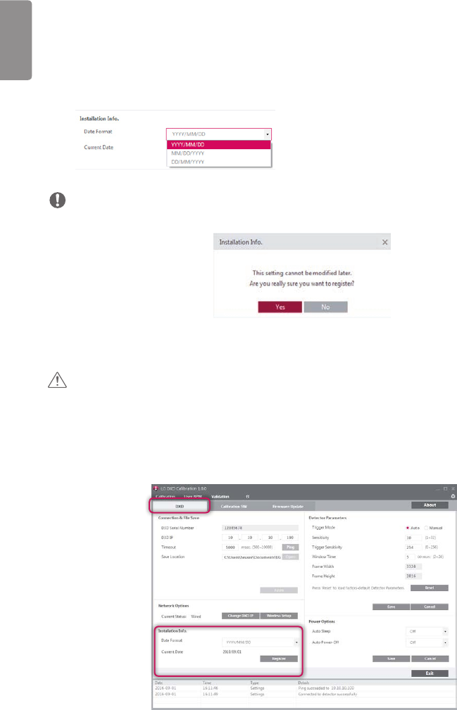
Storage of installation date
The date of the first calibration can be saved in the detector.
1 From the Usage section, perform "Launching the Program", "Checking IP Address and Ping Test", "Checking Save
Location" and "Apply".
2 Select the Settings > DXD tab.
3 Check the installation date and select a date format.
- YYYY: Year
- MM: Month
- DD: Day
NOTE
•The date is displayed based on the OS information.
4 Click the Register button to open a pop-up window. The installation date can be checked through the Web
Monitoring feature.
CAUTION
•Be careful, as this information is saved only once per detector and cannot be edited later.
5 Select the Yes button in the pop-up window to save the information in the detector. Once the information is saved,
the Register button will be disabled.
ENGLISH
111
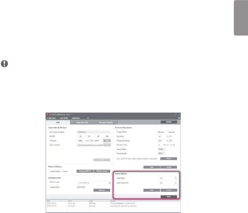
Power Options Setting
This menu allows you to save the Power Options of detector.
1 From the Usage section, perform "Launching the Program", "Checking IP Address and Ping Test", "Checking Save
Location" and "Apply".
2 Select the Settings > DXD tab.
3 Select the options of Auto Sleep and Auto Power-Off.
4 Click the Save button to save the options on Detector.
NOTE
•Calibration Software only saves the options.
•Detector enters the the Power Mode when there is no communication during the setting times.
•The Detector does not enter the Power Mode while the Calibration Softwere runs(from the “Apply” to exit) because
the Calibration Software checks the Detector‘s status Periodically.
•This feature is only enabled wireless models

ENGLISH
112
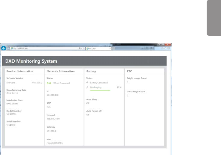
Web monitoring
This feature displays the detector's release date, installation date, software version and other internally managed
information in a web browser.
Internal Information
Category Content Description
Product
information
Software version •Currently installed detector firmware version
Product release date •Product manufacture date
Product installation
date
•Installation date as registered by the installer
Model number •Product model number
Serial No. •Product serial information
Network Connection status •Network connection mode (wired/wireless)
IP •Detector's IP address
SSID of the wireless
AP connected to the
detector
•ID of the wireless AP connected
Detector netmask
Detector gateway
MAC address of the
currently connected
network
•Product MAC information
Battery Status •Battery level, charging status notification, Auto Sleep , Auto Power off
ETC Bright image count •Number of times images were acquired by generating X-Rays
Dark image count •Number of times images were acquired without generating X-Rays
ENGLISH
113
Web monitoring
1 Establish a wired/wireless connection between the detector and the PC.
- Refer to the "Detector and PC(Wireless mode)" or "Detector and PC(Wireless mode)" sections for instructions.
2 Enter the IP address in the address input of the detector PC web browser.
3 The default IP address: 10.10.10.100 enter the page as below appears.

ENGLISH
114
MAINTENANCE
Cleaning
• Make sure to turn the detector off and remove the battery before cleaning.
Inspection
•Check the detector regularly to ensure that it operates stably and properly. If a problem occurs, please contact the
manufacture.
•Use the checklist below as a reference for checking the product.
Checklist Inspector Cycle
Is the cable damaged? User Daily
Is the plug or are the connectors loose or damaged? User Daily
Is the detector scratched or cracked on the surface? User Daily
Is the LED power working properly? User Daily
Is the battery charging properly? User Daily
Scheduled calibration Vendor 3 to 6 months
Performance inspection Vendor Yearly

ENGLISH
115
TROUBLESHOOTING
Problems that occur while using the detector can be solved by using the information on this page. If problems persist,
please contact the manufacturer.
Problem Action
The product does not turn on. •Check that the power cord is properly connected.
•After disconnecting and reconnecting the power cord, press the power button
on the product.
The product was suddenly turned
off during use.
•Check that the power cable is properly connected.
•After turning the product on again, check the detector battery status using
the battery LED. If flashing in orange, it means that the battery is low. Please
charge before use.
The Control Box Ready/Exposure
LED flashes in orange.
•Check the power cable connection of the control box.
•Check that the control box is properly connected to the generator or the
detector.
The PC and the detector are not
connected.
•Check the power supply. If on, check the following:
•Check that the connection is made as instructed in the manual. Try connecting
again.
•Perform the Ping Test in Settings > Connection & Save Location section
of Calibration Software to check your connection. You can also check your
connection by entering the IP address in the address bar of the Browser
window and checking whether the page is properly loaded.
•Check whether the network IP address of your PC is using the same IP address
as the detector.
•In some cases, especially Win 8 OS, it might be problem in connection because
of firewall rule that blocks all incoming ICMP packets. Please refet to next
page, "Solution for firewall block".
There is a problem with acquired
images.
•Check whether the detector surface is soiled.
•Images acquired immediately after turning the detector on may be incorrect
due to instability of the panel. Open the Calibration menu of the Calibration
Software. Acquire some dark images first or wait a while before proceeding.
•If the images continue to be unstable, perform Calibration, apply the results,
then continue.
ENGLISH
116
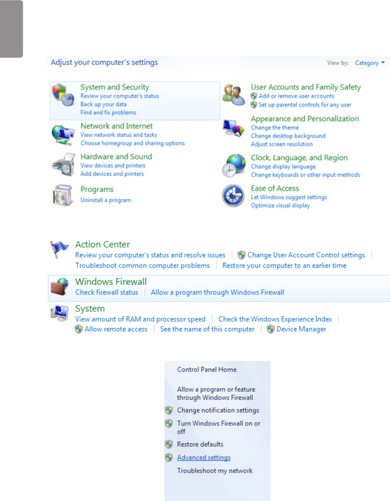
SOLUTION FOR FIREWALL BLOCK
If Calibration Software connection doesn’t work for firewall in Windows 8, refer to instructions as below.
1 Enter into control panel and click on the System and Security link
2 Select the Windows Firewall link.
3 Click on the Advanced settings link situated in the pane on the left hand side.
ENGLISH
117
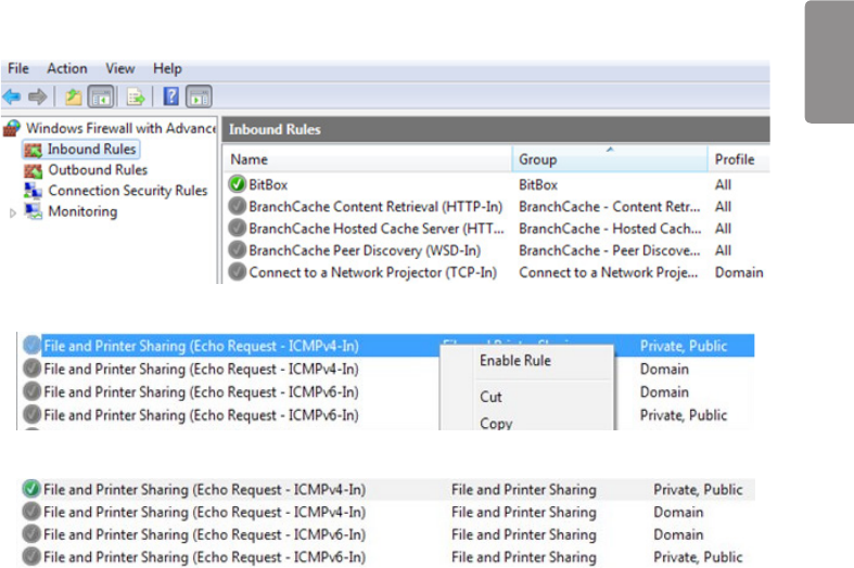
4 Choose Inbound rules in Windows Firewall with Advanced Security. Scroll and find File and Printer Sharing rule
to enable.
5 Click Enable Rule.
6 Check its status and try to connect detector again.
ENGLISH
118
SUPPLEMENT. WIRELESS AP SET UP
INSTRUCTION
(MODEL : Cisco Linksys EA9200)
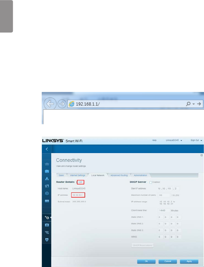
1 Connect the LAN Cable from the Ethernet port on the PC to the Ethernet port on the AP.
2 Launch your web browser and enter linksyssmartwifi.com or http://192.168.1.1 in the Address bar then press
Enter
(IP number address for the 1st access is 192.168.1.1. However, IP number address for accessing will be
10.10.10.1 after changing 10.10.10.1)
Enter into Connectivity > Local Network. Click Edit to change IP address to 10.10.10.1.
(You should click Apply button to apply current setting)
ENGLISH
119
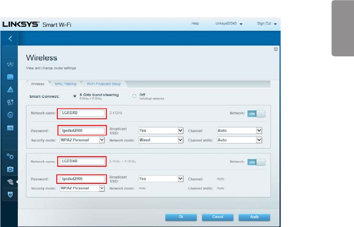
3 Enter into Wireless. You can change network name and password like below.
(You should click Apply button to apply current setting)
For more information, please visit the web site as below.
http://www.linksys.com/sg/support-product?pid=01t80000003efNkAAI

- YYYY: Year
- MM: Month
- DD: Day
To obtain the source code under GPL, LGPL, MPL, and other
open source licenses, that is contained in this product, please
visit http://opensource.lge.com.
In addition to the source code, all referred license terms,
warranty disclaimers and copyright notices are available for
download.
LG Electronics will also provide open source code to you
on CD-ROM for a charge covering the cost of performing
such distribution (such as the cost of media, shipping, and
handling) upon email request to opensource@lge.com. This
offer is valid for three (3) years from the date on which you
purchased the product.
Model
Serial No.

이 이이이 이이(이이이이)이이이이. 이이(이이, 이이이)이 이이 이이이이이 이이이 이 이이이이.
이 이이이 이이이 GPL, LGPL, MPL 이 이 이 이이이이 이이이이
이이 이이이 이이 이이이 이이이이,
http://opensource.lge.com이 이이이이이이.
이이 이이이 이이이이 이이이이 이이 이이이이이 이이 이 이이이
이이, 이이 이이이 이이이 이이이 이이이이이 이 이이이이.
이 이이이 이이이이 이 3 이 이이 opensource@lge.com 이
e-mail이 이이 이 이이이 이이이 이이이이이이 이이 이이
이이이 이이이이 이이, 이이 이이, 이이이 이 이이이 이이이
이이이이 이이이 이이 CD-ROM이 이이 이이이 이이이이.
모모
모모모 모모