LG Electronics USA M13 Cellular/ PCS CDMA 700 MHz LTE Transmitter User Manual M13
LG Electronics USA Cellular/ PCS CDMA 700 MHz LTE Transmitter M13
Users Manual

M13 Device description
Version 0.1 – APR 7th 2009

Part 15.21 statement
" Change or Modifications that are not expressly approved by the manufacturer could void
the user's authority to operate the equipment. “
Part 15.105 statement
This equipment has been tested and found to comply with the limits for a class B digital
device, pursuant to Part 15 of the FCC Rules.
These limits are designed to provide reasonable protection against harmful interference in
a residential installation. This equipment generates uses and can radiate radio frequency
energy and, if not installed and used in accordance with the instructions, may cause harmful
interference to radio communications. However, there is no guarantee that interference will
not occur in a particular installation. If this equipment does cause harmful interference or
television reception, which can be determined by turning the equipment off and on, the user
is encouraged to try to correct the interference by one or more of the following measures:
- Reorient or relocate the receiving antenna.
- Increase the separation between the equipment and receiver.
- Connect the equipment into an outlet on a circuit different from that to
which the receiver is connected.
- Consult the dealer or an experienced radio/TV technician for help.

Part 15 Class B Compliance
This device and its accessories comply with part15 of FCC rules.
Operation is subject to the following two conditions:
(1) This device & its accessories may not cause harmful interference.
(2) This device & its accessories must accept any interference received,
including interference that may cause undesired operation.

1.1 Feature
Copyright
Copyright © 2009 LG Electronics Inc. All Rights Reserved.
Though every care has been taken to ensure the accuracy of this document, LG Electronics Inc. cannot
accept responsibility for any errors or omissions or for any loss occurred to any person, whether legal or
natural, from acting, or refraining from action, as a result of the information contained herein.
Information in this document is subject to change at any time without obligation to notify any person of
such changes.
LG Electronics Inc. may have patents or patent pending applications, trademarks copyrights or other
intellectual property rights covering subject matter in this document. The furnishing of this document
does not give the recipient or reader any license to these patents, trademarks copyrights or other
intellectual property rights.
No part of this document may be communicated, distributed, reproduced or transmitted in any form or
by any means, electronic or mechanical or otherwise, for any purpose, without the prior written
permission of LG Electronics Inc.
The document is subject to revision without further notice.
All brand names and product names mentioned in this document are trademarks or registered
trademarks of their respective owners.
1.1. Feature
Caution
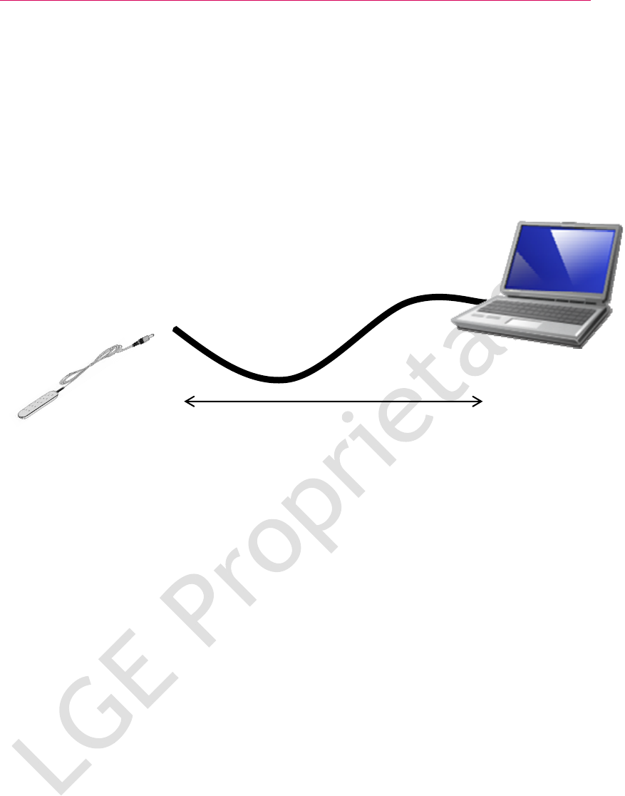
To comply with FCC RF exposure compliance requirements, a separation distance of at least 20 cm (8
inches) between the equipment and the body must be maintained.
<UE> <User>
At least 20 cm (8 inches)
M13
1.1. Feature
About This Document
Revision History
Version Date Comment Author
0.1 2009-04-07 Initial Draft Sang Ha Park
References

1.1. Feature
1 General Description
1.1 Feature
1.1 Feature
This document describes briefly the board level operations, key features and the
environment of the M13 Platform. The purpose of this platform is the verification of
LG LTE ASIC, namely ‘L1000’, and the evaluation of LG UE system performance. The
further details about the characteristics and functions of L1000 are available on other
documents. M13 consists of a CDMA main board, a LTE sub board.
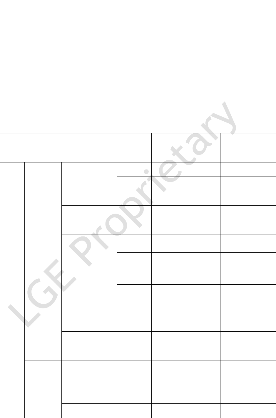
<Table 1. M13 Device Feature>
Specification LTE only
Remark
SW Date 31-May-30
LTE USB 2.0 High Speed
Interface Spec.
CDMA USB 2.0 Full Speed
External port Micro USB 1 Port
LTE 3GPP Rel. 8 (Dec. 2008)
Standard(SW ver.)
CDMA N/A
LTE 3GPP Band 13
(700 MHz Upper C block)
Band support
CDMA N/A
LTE L1000 (by LGE)
Main chipset
CDMA MSM6800A (by QCT)
LTE DL 50Mbps / UL 25Mbps
(Category2)
Max. Data rate
CDMA N/A
GPS Not Support
General
Battery Support
Tx Diversity LTE Not support UE Antenna
Selection will not
be supported
Max. Tx Power LTE 23 dBm At antenna port
HW
Transmitter
Band Width LTE 10MHz
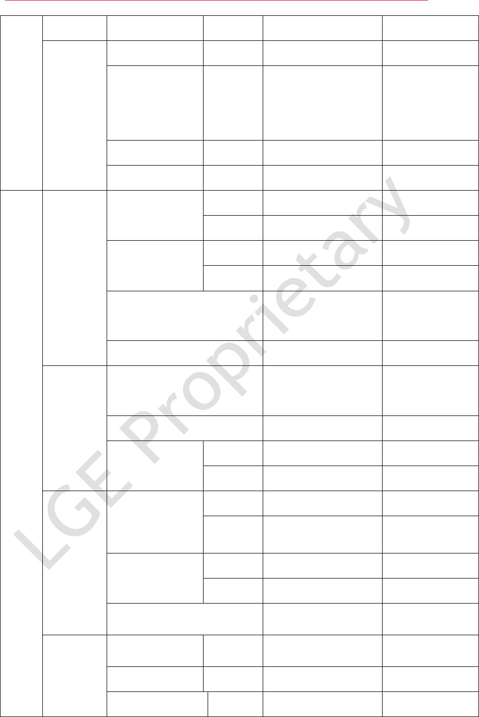
1.1. Feature
Modulation Method LTE Up to 16QAM
Rx Diversity LTE Support
MIMO LTE 2x2 MIMO Adaptive
switching
between downlink
Transmit Diversity
and SU MIMO
Band width LTE 10MHz
Receiver
Modulation Method LTE Up to 64QAM
LTE USB Ethernet
Interface protocol
CDMA N/A
LTE 3 Ports (Data, DM, Control)
USB Driver
CDMA 3 Ports (Data, DM, Control)
Downloading Tool Support Downloading tool
for field upgrade
through USB port
Interface
DM (Diagnostic Monitor) Support LGE tool for LTE
Prefered system selection Support 'LTE only' mode LTE only'
'LTE preferred'
'eHRPD only'
Support System LTE only
LTE Support PLMN
System
selection
PRL/PLMN List
CDMA N/A
LTE Device
User Identity Module
(IMSI)
CDMA N/A
LTE Not Support
Authentication
CDMA N/A
Authentication
&
Identity
Numbering & Identities NAI based upon the IMSI
11digit MDN
IPv4/6 dual IP stack LTE Support for IPv4/6 (need to test
with Network)
CDMA N/A
SW
IP support
DHCP LTE N/A
1.1 Feature
CDMA N/A
LTE Proxy mobile IPv4/6
IP Mobility
eHRPD N/A
LTE Support
QoS QoS
CDMA N/A
Active handoff N/A Non optimized
handover
Idle handoff N/A Non optimized
handover
IRAT handoff
IRAT measurement N/A
Dimensions (W xD xH) 185 x 133.9 x 22.8 mm
Weight 420g
Mechani
cal Mechanical
Antenna Internal Antenna (MIMO)

2 Mechanical description
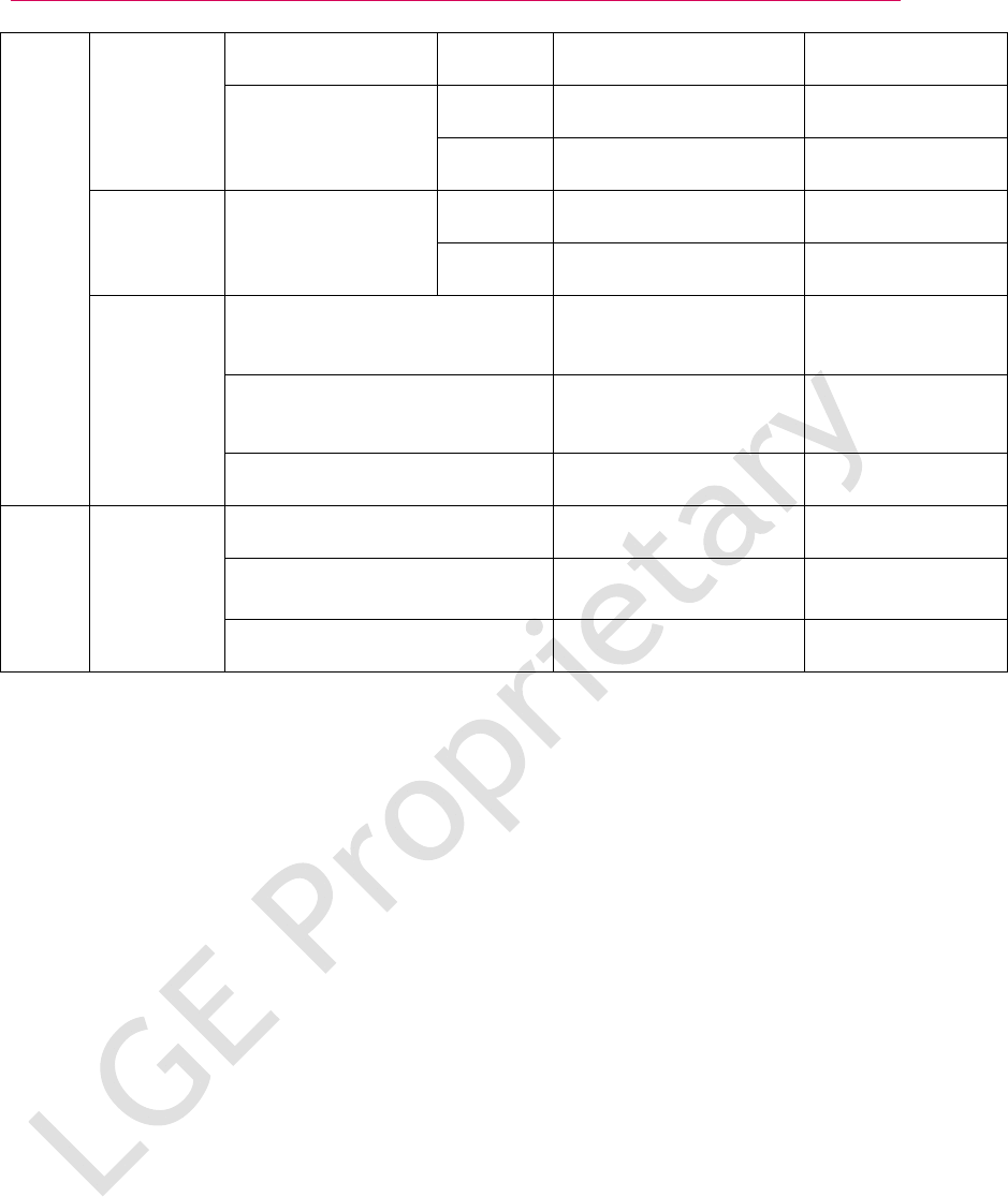
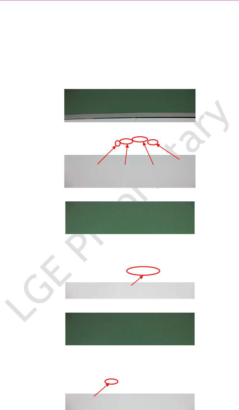
2.1 Front / Rear / Side View
2.1 Front / Rear / Side View
<Fig 4-1. M13 Mechanical Part Top View>
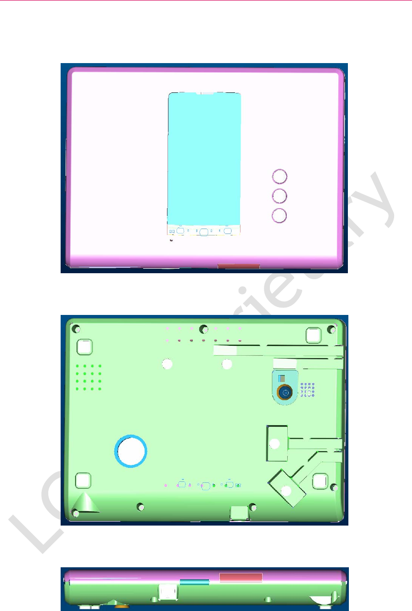
<Fig 4-2. M13 Mechanical Part Bottom View>
<Fig 4-3. M13 Mechanical Part Side 1 View>
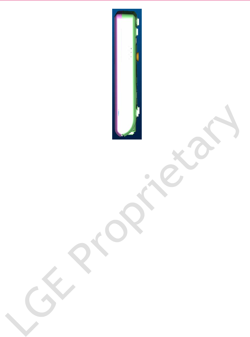
2.1. Front / Rear / Side View
<Fig 4-4. M13 Mechanical Part Side 2 View>

2.2 Dimension
2.2 Dimension
M13 Mechanical dimension is 133.9 x 185 x 22.8mm.

2.2. Dimension
3 Functional description
3.1 Functional Key description
3.1 Functional Key description
LTE trial device picture is below.
<Fig 5.1 LTE & eHRPD LTE Trial Product Picture>
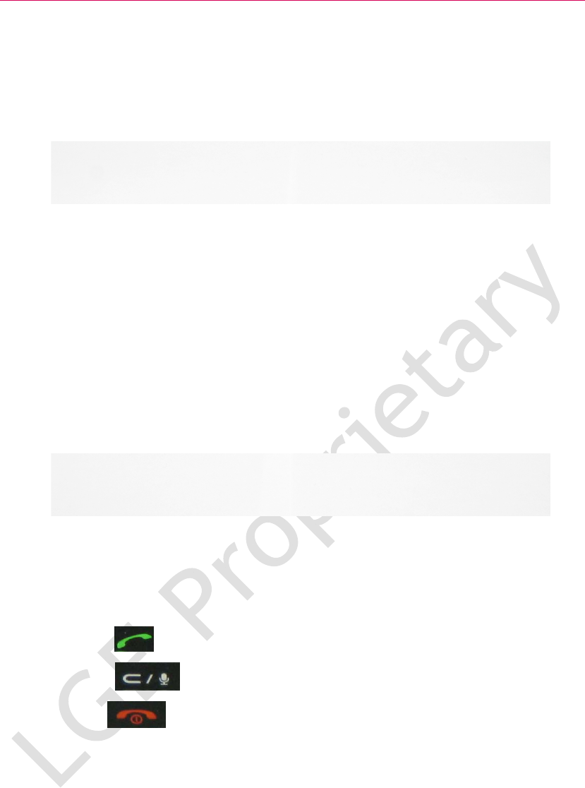
This product has some key to operate LTE trial device.
Send key : This key is used to call.
Clear key : This key is used to erase character or number.
End key : This key is used to disconnect a call and stop to function.
3.2. External connector description
3.2 External connector description
Our LTE Trail device has several external connectors.
DC input jack connector: External Power source, 5V TA
USB connector: USB Connect to Host (PC)
SIM socket: for LTE Authentification
24Pin connector: For debug LTE Sub board
DC input Jack USB cap SIM socket cap
24Pin connector for LTE Sub board debugging
Earphone jack connector
HW Reset key

3.3 External RF connector description
3.3 External RF connector description
LTE Trial device has 4 external RF connectors in order to measure wired RF
performance characteristic.
It is configured that LTE ant part is two external ANT port; LTE main ANT mobile
switch and LTE MIMO ANT mobile switch, and CDMA ANT mobile.
If you want to test LTE RF performance, you can use this external ANT port.
CDMA ANT Mobile SW
GPS ANT mobile SW
LTE MIMO ANT mobile SW LTE Main ANT mobile SW
3.4. Antenna description (LTE & CDMA)
3.4 Antenna description (LTE & CDMA)
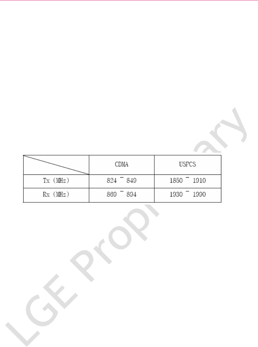
3.4.1 CDMA Antenna description
M13 Device LTE Antenna: Dual band, Single Feeding Antenna
Type: Carrier & PIFA
Directive: Omni-directiona
Ant. : 1TX and 1RX
CDMA 3D Gain: TX:--5.9dB, RX: -3.7dB
USPCS 3D Gain: TX: -6.1dB, RX: -5.1dB
Max Power: 2W (Maximum)
Band Support
3.4.2 LTE Antenna description
M13 Device LTE Antenna: MIMO Antenna
Type: Carrier & PIFA
Directive: Omni-directional
LTE Band 13 Support: UL; 777~787(MHz), DL;746~768(MHz)
Antenna Band: 740 ~ 800 (MHz)
Max power: 2W(Maximum)
Primary Ant. : 1TX and 1RX
Secondary Ant.: 1RX
3D Primary Antenna Gain: -1.32dB(Average)
3D Secondary Antenna Gain: -1.34(Average)
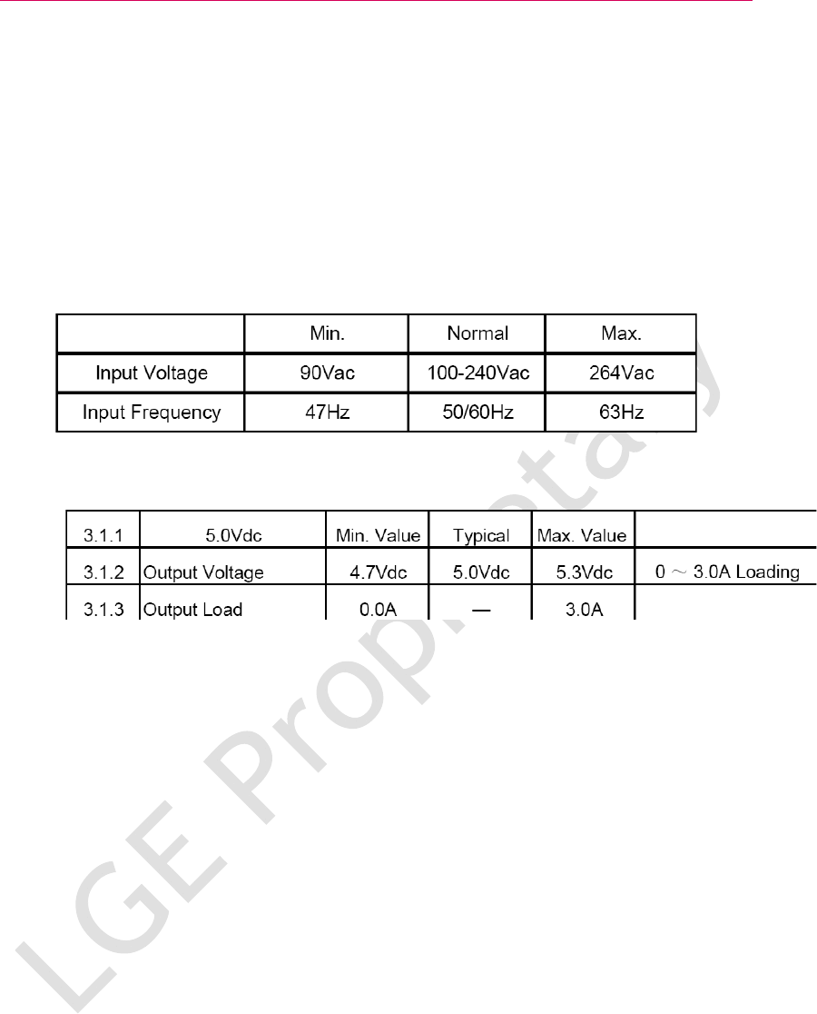
3.5 External Power description
3.5 External Power description
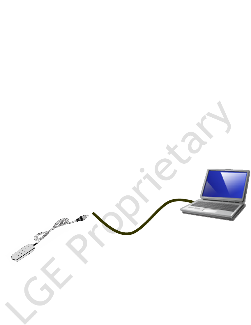
To operate and charge the battery, plug the AC Adapter into a standard wall outlet
and connect it to the LTE trial device via the DC input jack Connector.
External power supply is DC input jack or TA. This power supply specification is
below.
Input Voltage & Current
Output Voltage & Current
3.6 Battery description
3.6 Battery description
Our LTE Trial device has a two Battery. One is used for operating CDMA modem part,
and another is used for operating LTE modem part.
Battery Capacity for used in CDMA part is 1100mAh.
But in order to operating fully LTE performance, it is need to larger battery capacity.
And then we selected 2400mAh cylindrical battery.
Total Battery capacity is 3600mAh
If the battery’s charge is completely run down, it takes 6 to 7 hours to fully recharge.
But this battery capacity is not enough to operate LTE capability; you should external
power supply, which is TA (Travel Adaptor). The mandatory power supply of the LTE
UE is supplied by TA which is distributed by the LGE.
<USB Cable>
<Travel Adaptor>
M13