LG Electronics USA M203WXB 20.1” LCD Monitor User Manual Microsoft PowerPoint F User s Manual
LG Electronics USA 20.1” LCD Monitor Microsoft PowerPoint F User s Manual
Users Manual

FCC ID : BEJM203WXB
APPENDIX F :
USER’S MANUAL
1 / 47
1
FCC Compliance Statement
This equipment has been tested and found to comply within
the limits of a Class B digital device pursuant to Part 15 of
the FCC Rules. These limits are designed to provide
reasonable protection against harmful interference in a
residential installation.
This equipment generates, uses, and can radiate radio
frequency energy and if not installed and used in
accordance with the instructions, may cause harmful
interference to radio communications. However, there is no
guarantee that interference will not occur in a particular
installation.
If this equipment does cause harmful interference to radio
or television reception (which can be determined by turning
the equipment on and off), the user is encouraged to try to
correct the interference by using one or more of the
following measures:
Reorient or relocate the receiving antenna.
Increase the separation between the equipment and the
receiver.
Connect the equipment into an outlet on a circuit
different from that to which the receiver is connected.
Consult the dealer or an experienced radio/TV
technician for help.
Caution: Changes or modifications not expressly approved
by the party responsible for compliance could void the
user's (or your) authority to operate the equipment. Only
peripherals (digital input/output devices, terminals, printers,
etc.) certified to comply with the Class B limits may be
attached to this monitor. Operation with non-certified
peripherals is likely to result in interference to radio and TV
reception.
Only shielded signal cables may be used with this System.
Canadian DOC Notice
This Class B digital apparatus meets all requirements of the
Canadian Interference-Causing Equipment Regulations.
Cet appareil numérique de la classe B respecte toutes les
exigences du Règlement sur le matériel brouilleur du
Canada.
CE Conformity Notice (for Europe)
Products with the “CE” Marking comply with the EMC
Directive(89/336/EEC) and LOW VOLTAGE Directive
(73/23/EEC) issued by the Commission of the European
Community.
Compiance with these directives implies conformity to the
following European Norms :
• EN 55022:1998 ; Radio Frequency Interference
• EN 55024:1998 ; Electromagnetic Immunity
• EN 61000-3-2 ; Power Line Harmonics
• EN 61000-3-3 ; Voltage Fluctuations
• EN 60950 ; Product Safety
Low Radiation Compliance (MPR II)
This monitor meets one of the strictest guidelines available
today for low radiation emissions, offering the user extra
shielding and an antistatic screen coating. These
guidelines, set forth by a government agency in Sweden,
limit the amount of emission allowed in the Extremely Low
Frequency (ELF) and Very Low Frequency (VLF)
electromagnetic range.
TCO95
Congratulations!
You have just purchased a TCO’95 approved and labelled
product! Your choice has provided you with a product
developed for professional use. Your purchase has also
contributed to reducing the burden on the environment and
to the further development of environmentally-adapted
electronic products.
Why do we have environmentally labelled computers?
In many countries, environmental labelling has become an
established method for encouraging the adaptation of
goods and services to the environment. The main problem
as far as computers and other electronic equipment are
concerned is that environmentally harmful substances are
used both in the products and during their manufacture.
Since it has not been possible so far for the majority of
electronic equipment to be recycled in a satisfactory way,
most of these potentially damaging substances sooner or
later enter Nature.
There are also other characteristics of a computer, such as
energy consumption levels, that are important from both the
working and natural environment viewpoints. Since all
types of conventional electricity generation have a negative
effect on the environment (acidic- and climatic-influencing
emissions, radioactive waste, etc.), it is vital to conserve
energy. Electronic equipment in offices consumes as
enormous amount of energy, since it is often routinely left
running continuously.
What does the environmenal labelling involve?
This product meets the requirements for the TCO’95
Regulatory Information
NOTICE
The regulations are applied only to the products with the
ID LABEL indicating specific requirements.
NOTICE
The regulations are applied only to the products with the
ID LABEL indicating specific requirements.
NOTICE
The regulations are applied only to the products with the
ID LABEL indicating specific requirements.
2
Regulatory Information cont.
NUTEK
Naturskydds
föreningen
Närings- och teknikutvecklingsverket
SEMKO
scheme, which provides for international environmental
labelling of personal computers. The labelling scheme was
developed as a joint effort by the TCO (The Swedish
Confederation of Professional Employees),
Naturckyddsföreningen (The Swedish Society for Nature
Conservation), and NUTEK (The National Board for
Industrial and Technical Development in Sweden), and
SEMKO AB (an international certification agency).
The requirements cover a wide range of issues:
environment, ergonomics, usability, emission of electrical
and magnetic fields, energy consumption and electrical and
fire safety.
The environmental demands concern, among other things,
restriction on the presence and use of heavy metals,
brominated and chlorinated flame retardants, CFCs
(freons), and chlorinated solvents. The product must be
prepared for recycling, and the manufacturer is obliged to
have an environmental plan, which must be adhered to in
each country where the company implements its
operational policy.
The energy requirements include a demand that the
computer and/or display, after a certain period of inactivity,
shall reduce its power consumption to a lower level, in one
or more stages. The length of time to reactivate the
computer shall be reasonable for the user.
Labelled products must meet strict environmental
demands, for example, in respect of the reduction of electric
and magnetic fields, along with physical and visual
ergonomics and good usability.
The following is a brief summary of the environmental
requirements met by this product. The complete
environmental criteria document may be ordered from:
TCO Development Unit
Linnegatan 14, S-11494 Stockholm, Sweden
FAX +46-8 782 92 07
E-mail (Internet): development@tco.se
Current information regarding TCO’95 approved and
labelled products may also be obtained on the Internet
using the address: http://www.tco-info.com/
TCO’95 is a co-operative project between:
Environmental requirements
Brominated flame retardants are present in printed circuit
boards, cabling, casings, and housings, and are added to
delay the spread of fire. Up to 30% of the plastic in a
computer casing can consist of flame-retardant substances.
These are related to another group of environmental toxins,
PCBs, and are suspected of giving rise to similar harm,
including reproductive damage in fish-eating birds and
mammals. Flame retardants have been found in human
blood, and researchers fear that they can disturb fetus
development.
Bio-accumulative1TCO’95 demands require that plastic
components weighing more than 25 grams must not
contain flame retardants with organically bound chlorine or
bromine.
Lead can be found in picture tubes, display screens, solder,
and capacitors. Lead damages the nervous system and in
higher doses causes lead poisoning. The relevant bio-
accumulative TCO’95 requirement permits the inclusion of
lead, as no replacement has yet been developed.
Cadmium is present in rechargeable batteries and in the
color-generating layers of certain computer displays.
Cadmium damages the nervous system and is toxic in high
doses. The relevant bio-accumulative TCO’95 requirement
states that batteries may not contain more than 25 ppm
(parts per million) of cadmium. The color-generating layers
of display screens must not contain any cadmium.
Mercury is sometimes found in batteries, relays and
switches. Mercury damages the nervous system and is
toxic in high doses. The relevant bio-accumulative TCO’95
requirement states that batteries may not contain more than
25 ppm of mercury and that no mercury is present in any of
the electrical or electronic components concerned with the
display unit.
CFCs (freons) are sometimes used for washing printed
circuit boards and in the manufacture of expanded foam for
packaging. CFCs break down ozone and thereby damage
the ozone layer in the atmosphere, causing increased
reception on Earth of ultra-violet light with consequent
increased risks of skin cancer (malignant melanoma). The
relevant TCO’95 requirement: Neither CFCs nor HCFCs
may be used during the manufacture of the product or its
packaging.
1Bio-accumulative means that the substance accumulates
within living organisms.
Shipping Package
The packaging material can be recycled, or you can save it
to return the monitor to a service center for repair or
disposal.
CFC Compounds in Distribution Packaging
Cushioning material used for shipping finished monitors are
not manufactured with nor do they contain any CFC
compounds.
Design for Disassembly/Recycling
These monitors have been designed for easy end-of-life
disassembly and recycling. Fasteners are generally of the
same type for efficient disassembly. Components made of
different materials can be easily separated and plastics
have been identified using intermational symbols to aid in
recycling.
Monitor Disposal
WARNING
If you need to dispose of a monitor, ask a qualified service
representative for the proper procedure. Improper disposal
could result in personal injury from implosion.

3
TCO99
Congratulations!
You have just purchased a TCO’99 approved and
labelled product! Your choice has provided you with
a product developed for professional use. Your
purchase has also contributed to reducing the
burden on the environment and also to the further
development of environmentally adapted electronics
products.
Why do we have environmentally labelled
computers?
In many countries, environmental labelling has
become an established method for encouraging the
adaptation of goods and services to the environment.
The main problem, as far as computers and other
electronics equipment are concerned, is that
environmentally harmful substances are used both in
the products and during their manufacture. Since it is
not so far possible to satisfactorily recycle the
majority of electronics equipment, most of these
potentially damaging substances sooner or later
enter nature.
There are also other characteristics of a computer,
such as energy consumption levels, that are
important from the viewpoints of both the work
(internal) and natural (external) environments. Since
all methods of electricity generation have a negative
effect on the environment (e.g. acidic and climate-
influencing emissions, radioactive waste), it is vital to
save energy. Electronics equipment in offices is
often left running continuously and thereby
consumes a lot of energy.
What does labelling involve?
This product meets the requirements for the TCO’99
scheme which provides for international and
environmental labelling of personal computers. The
labelling scheme was developed as a joint effort by
the TCO (The Swedish Confederation of
Professional Employees), Svenska
Naturskyddsforeningen (The Swedish Society for
Nature Conservation) and Statens Energimyndighet
(The Swedish National Energy Administration).
Approval requirements cover a wide range of issues:
environment, ergonomics, usability, emission of
electric and magnetic fields, energy consumption
and electrical and fire safety.
The environmental demands impose restrictions on
the presence and use of heavy metals, brominated
and chlorinated flame retardants, CFCs (freons) and
chlorinated solvents, among other things. The
product must be prepared for recycling and the
manufacturer is obliged to have an environmental
policy which must be adhered to in each country
where the company implements its operational
policy.
The energy requirements include a demand that the
computer and/or display, after a certain period of
inactivity, shall reduce its power consumption to a
lower level in one or more stages. The length of time
to reactivate the computer shall be reasonable for
the user.
Labelled products must meet strict environmental
demands, for example, in respect of the reduction of
electric and magnetic fields, physical and visual
ergonomics and good usability.
Below you will find a brief summary of the
environmental requirements met by this product. The
complete environmental criteria document may be
ordered from:
TCO Development
SE-114 94 Stockholm, Sweden
Fax: +46 8 782 92 07
Email (Internet): development@tco.se
Current information regarding TCO’99 approved and
labelled products may also be obtained via the Internet,
using the address: http://www.tco-info.com/
Environmental requirements
Flame retardants
Flame retardants are present in printed circuit
boards, cables, wires, casings and housings. Their
purpose is to prevent, or at least to delay the spread
of fire. Up to 30% of the plastic in a computer casing
can consist of flame retardant substances. Most
flame retardants contain bromine or chloride, and
those flame retardants are chemically related to
another group of environmental toxins, PCBs. Both
the flame retardants containing bromine or chloride
and the PCBs are suspected of giving rise to severe
health effects, including reproductive damage in
fish-eating birds and mammals, due to the bio-
accumulative* processes. Flame retardants have
been found in human blood and researchers fear
that disturbances in foetus development may occur.
The relevant TCO’99 demand requires that plastic
components weighing more than 25 grams must not
contain flame retardants with organically bound
bromine or chlorine. Flame retardants are allowed in
the printed circuit boards since no substitutes are
available.
Cadmium**
Cadmium is present in rechargeable batteries and in
the colour-generating layers of certain computer
displays. Cadmium damages the nervous system
and is toxic in high doses. The relevant TCO’99
requirement states that batteries, the colour-
generating layers of display screens and the
electrical or electronics components must not contain
any cadmium.
Regulatory Information cont.
4
Regulatory Information cont.
Mercury**
Mercury is sometimes found in batteries, relays and
switches. It damages the nervous system and is
toxic in high doses. The relevant TCO’99
requirement states that batteries may not contain
any mercury. It also demands that mercury is not
present in any of the electrical or electronics
components associated with the labelled unit.
CFCs (freons)
The relevant TCO’99 requirement states that neither
CFCs nor HCFCs may be used during the
manufacture and assembly of the product. CFCs
(freons) are sometimes used for washing printed
circuit boards. CFCs break down ozone and thereby
damage the ozone layer in the stratosphere, causing
increased reception on earth of ultraviolet light with
e.g. increased risks of skin cancer (malignant
melanoma) as a consequence.
Lead**
Lead can be found in picture tubes, display screens,
solders and capacitors. Lead damages the nervous
system and in higher doses, causes lead poisoning.
The relevant TCO’99 requirement permits the
inclusion of lead since no replacement has yet been
developed.
* Bio-accumulative is defined as substances which
accumulate within living organisms
** Lead, Cadmium and Mercury are heavy metals which are
Bio-accumulative.
EPA (U.S.A only)
ENERGYSATR is a set of power-saving guidelines
issued by the U.S. Environmental Protection
Agency(EPA).
NOM MARK (Mexico only)
GOST MARK
EPA POLLUTION PREVENTER
As an ENERGY STAR Partner LG
Electronics U.S.A.,Inc. has
determined that this product meets the
ENERGY STAR guidelines for
energy efficiency.
BZ03
Internet Address:http://www.lg.ru
»ÌÙÓχˆËÓÌ̇ˇ ÒÎÛÊ·‡ LG
Electronics (095)742-77-77
i
A1
A4
A5
A7
A8
A17
A17
A20
A22
A23
Safety Precautions
Accessories
Before connecting to the PC
Important Product Features
Name and Function of the Parts
Connecting to External Devices
When connecting to your PC
When watching Video / DVD
When watching TV
To arrange the cables
A37
A40
Selecting and Adjusting the Screen
Name of the Buttons in the screen Adjustment Unit
OSD (On Screen Display) Screen Tracking Order
How to adjust the OSD (On Screen Display) screen.
Set/Selects the channel when using the TV
Adjusting Screen Colour
Adjusting the audio function
Adjusting the timer function
Selecting the SPECIAL
Adjusting Screen Clock/Phase and Position
Adjusting PIP/POP/PBP Mode Functions
A24
A24
A26
A27
A28
A30
A31
A32
A33
A34
A35
Troubleshooting
Specifications
Installation
and
Connection
Input
Selection
and Tracking
Miscellaneous
Table of Contents
ENGLISH
is a trademark of SRS Labs,Inc.
technology is incorporated under license from SRS Labs,Inc.
A1
Please read these safety precautions carefully before using the product.
Precautions in installing the Product
If you ignore the caution message, you may be slightly injured or the product may be damaged
If you ignore the warning message, you may be seriously injured or there is a possibility of
accident or death.
Keep away from heat sources like electrical heaters.
- Electrical shock, fire, malfunction or deformation may occur.
Keep the packing anti-moisture material or vinyl packing out of the reach of children.
- Anti-moisture material is harmful if swallowed. If swallowed by mistake, force the patient to vomit and visit the
nearest hospital. Additionally, vinyl packing can cause suffocation. Keep it out of the reach of children.
Do not put heavy objects on the product or sit upon it.
- If the product collapses or is dropped, you may be injured. Children must pay particular attention.
Do not leave the power or signal cable unattended on the pathway.
- The passerby can falter, which can cause electrical shock, fire, product breakdown or injury.
Install the product in a neat and dry place.
- Dust or moisture can cause electrical shock, fire or product damage.
If you can smell smoke or other odors or hear a strange sound unplug the power cord and contact the
service center.
- If you continue to use without taking proper measures, electrical shock or fire can occur.
If you dropped the product or the case is broken, turn off the product and unplug the power cord.
- If you continue to use without taking proper measures, electrical shock or fire can occur. Contact the service
center.
Do not drop metallic objects such as coins, hair pins, chopsticks or wire into the product, or inflammable
objects such as paper and matches. Children must pay particular attention.
- Electrical shock, fire or injury can occur. If a foreign object is dropped into the product, unplug the power cord and
contact the service center.
Make sure the product ventilation hole is not blocked. Install the product in a suitably wide place (more
than 10cm from the wall)
- If you install the product too close to the wall, it may be deformed or fire can break out due to internal heat.
Do not block the ventilation hole of the product by a tablecloth or curtain.
- The product can be deformed or fire can break out due to overheating inside the product.
Install the product on a flat and stable place that has no risk of dropping the product.
- If the product is dropped, you may be injured or the product may be broken.
Install the product where no EMI occurs.
Keep the product away from direct sunlight.
- The product can be damaged.
Safety Precautions
Warning
Warning
Caution
Caution
A2A2
Electrical Power Related Precautions
Make sure to connect the power cable to the grounded current.
- You may be electrocuted or injured.
Use the rated voltage only.
- The product can be damaged, or you may be electrocuted.
During a thunder or lightning storm, unplug the power cable or signal cable.
- You may be electrocuted or a fire can break out.
Do not connect several extension cords, electrical appliances or electrical heaters to a single outlet. Use a
power bar with a grounding terminal designed for exclusive use with the computer.
- A fire can break out due to overheating.
Do not touch the power plug with wet hands. Additionally, if the cord pin is wet or covered with dust, dry
the power plug completely or wipe dust off.
- You may be electrocuted due to excess moisture.
If you don’t intend to use the product for a long time, unplug the power cable from the product.
- Covering dust can cause a fire, or insulation deterioration can cause electric leakage, electric shock or fire.
Fix the power cable completely.
- If the power cable is not fixed completely, a fire can break out.
Hold the plug when pulling out the power cable. Do not bend the power cord with excessive force or put
heavy objects on the power cord.
- The power line can be damaged, which may cause electric shock or fire.
Do not insert a conductor (like a metal chopstick) into one end of the power cable while the other end is
connected to the input terminal on the wall. Additionally, do not touch the power cable right after
plugging into the wall input terminal.
- You may be electrocuted.
Do not unplug the power cord while the product is in use.
- Electrical shock can damage the product.
Warning
Caution
ENGLISH
Precautions in Moving the Product
Warning
Make sure to turn off the product.
- You may be electrocuted or the product can be damaged.
Make sure to remove all cables before moving the product.
- You may be electrocuted or the product can be damaged.
A3A3
Safety Precautions
Caution
Precautions in Using the Product
Warning
Do not put or store inflammable substances near the product.
- There is a danger of explosion or fire due to careless handling of the inflammable substances.
When cleaning the brown tube surface, unplug the power cord and scrub with soft cloth to prevent
scratching. Do not clean with a wet cloth.
- The water can sink into the product, which can cause electric shock or serious malfunction.
Take a rest from time to time to protect your vision.
Keep the product clean at all times.
Take a comfortable and natural position when working with a product to relax the muscles.
Take a regular break when working with a product for a long time.
Do not press strongly upon the panel with a hand or sharp object such as nail, pencil or pen, or make a
scratch on it.
Keep the proper distance from the product.
- Your vision may be impaired if you look at the product too closely.
Set the appropriate resolution and clock by referring to the User’s Manual.
- Your vision can be impaired.
Use authorized detergent only when cleaning the product. (Do not use benzene, thinner or alcohol.)
- Product can be deformed.
Caution
Do not shock the product when moving it.
- You may be electrocuted or the product can be damaged
Do not dispose the product-packing box. Use it when you move.
Make the panel face forward and hold it with both hands to move.
- If you drop the product, the damaged product can cause electric shock or fire. Contact with the service center for
repair.
Do not disassemble, repair or modify the product at your own discretion.
- Fire or electric shock accident can occur.
- Contact the service center for check, calibration or repair.
Do not spray water on the product or scrub with an inflammable substance (thinner or benzene). Fire or
electric shock accident can occur
Keep the product away from water.
- Fire or electric shock accident can occur.
The fluorescent lamp used in this product contains a small amount of mercury.
Do not dispose of this product with general household waste.
Disposal of this product must be carried out in accordance to the regulations of your local authority.
On Disposal
A4A4
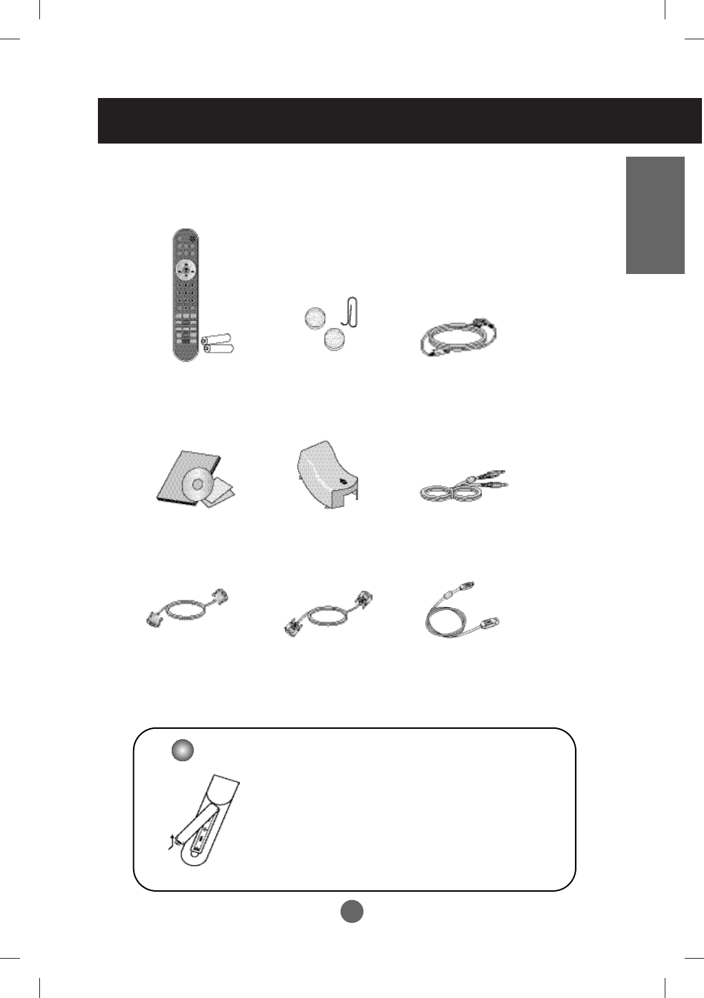
Remote Control
/Batteries (2ea)
Power Cord
Audio Cable (PC)
Please check the accessories in the product package.
* The product and the accessories can be different from the figures shown here.
D-Sub Signal Cable DVI-D Signal Cable
ENGLISH
Accessories
Cable Cap
User's Guide / Drive CD
Cards
USB Cable
(only applies to the
20.1 inch product)
1. Take out the battery cap.
2. Insert the battery with correct polarity (+/-).
3. Close the battery cap.
• You can use a remote control 7 meter distance
and 30 degree (left/right) within the receiving unit
scope.
• Dispose of used batteries in the recycle bin to
prevent environmental pollution.
Inserting batteries into remote control.
Speaker Cover (2ea)
/Cover Picker
A5
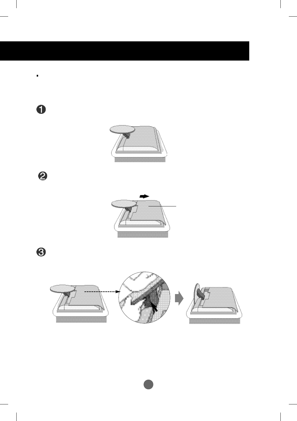
Before Connecting to the PC
Before setting up the product, ensure that the power to the product, the computer
system, and other attached devices is turned off.
Unfolding the stand base
Place the product with its front facing downward on a cushion or soft cloth.
Hold down the release button inside the stand and strongly pull out the stand with
your two hands.
The stand won't move if you don't press release button.
If the release button does not operate easily, fold the
stand a bit more, and then press the release button.
Push up the back cap.
Back Cover
A6
ENGLISH
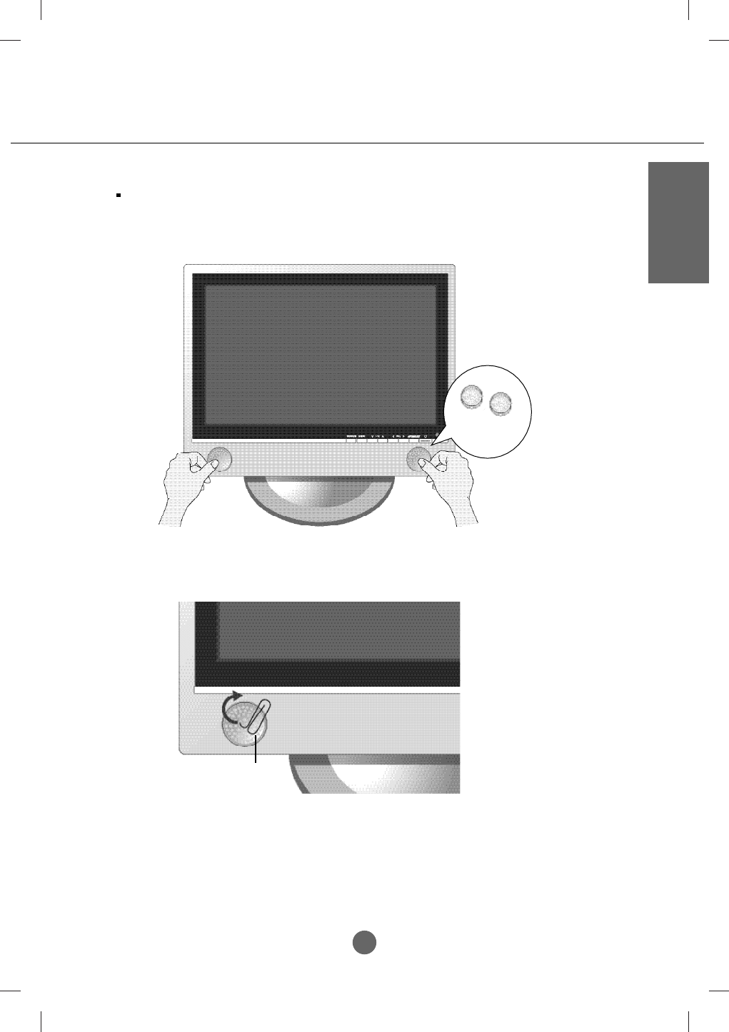
Installing the speaker cover
Removing the speaker cover
speaker
cover
Cover Picker
Install the speaker covers on the both sides of the speaker for protection.
Installing and removing the cover on/from the speaker

A7
Swapping Function
You can swap the main screen and the sub-screen when the PIP/POP/PBP function is used.
Spectacle Function
The screen center area is close to a 4:3 ratio and the outskirt area is expanded by more than
Spectacle. Therefore, the different screen ratio is applied for each area. Because most ordinary
people concentrate their focus on the screen center, a non-linear ratio increase at the outskirt area is
not recognized, which makes it possible to watch 4:3 TV screen with a wide screen.
However, the spectacle function is useful in watching TV or motion pictures but is not suitable for the
PC environment in which you perform graphic or document work.
Sleep Function
When watching AV/TV – The product will be automatically turned off after a certain period of time.
Press this button repetitively to select an appropriate time duration.
Media Manager (only 20.1 inch)
With this card, you are free to watch pictures and video, and enjoy listening to music without turning
on your computer.
Important Product Features
A8
ENGLISH
Name and Function of the Parts
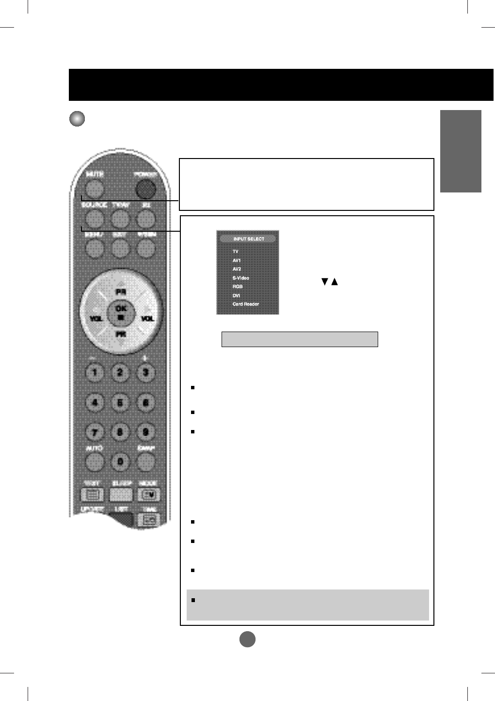
Name of the Remote Control Buttons
MUTE
Use the this button so that no sound comes out temporarily.
POWER
Able to power On/Off.
SOURCE
TV/AV :
TV/AV button
I/II : Bilingual choice and sound mode selection
Press this button
[TV]
to switch from Stereo to Mono sound in case of stereo transmission, or
from Nicam Stereo to Nicam Mono, in case of digital transmission.
to switch from Nicam Dual Ito Nicam Dual II or Nicam Dual I+II in
case of Nicam Dual transmission.
to choose between Dual I, Dual II or Dual I+II in case of bilingual
transmission :
Dual I sends the primary broadcast language to the loudspeakers ;
Dual II sends the secondary broadcast language to the loudspeakers ;
Dual I+II sends a separate language to each loudspeakers.
[AV]
In AV mode, you can select output sound for the left and right
loudspeakers.
Repeatedly press the I/II button to select the sound output.
L+L : Audio signal from audio L input is sent to
left and right loud-speakers.
L+R : Audio signal from audio L input is sent
to left loud-speaker and audio signal from
audio R input is sent to right loud-speaker.
R+R : Audio signal from audio R input is sent
to left and right loud- speakers.
If you press the button once,
the following Input Signal
Window will appear. Select
the signal type you want
using the button.
TV >AV1 >AV2 >S-Video
NOTE : In case of weak stereo sound signals, with stereo or Nicam stereo
transmission, select mono reception.
Remote Control
* Card Reader : Optional
*
A9
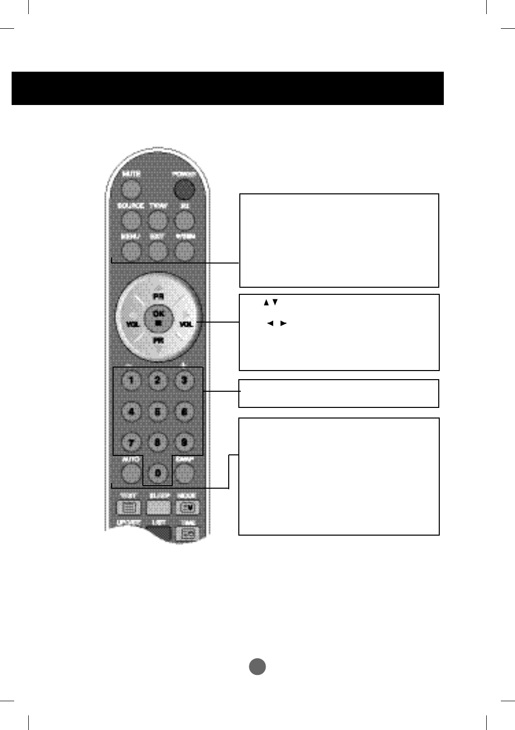
Name and Function of the Parts
PR ( ) Buttons
Able to change channel.
VOL ( ) Buttons
Able to adjust sound.
OK Button
Use when functional adjustment is completed.
AUTO Button
•
This function is to automatically search the available
channels. It is available to the TV signal inputs only.
•
This function is to automatically adjust your display
image to the ideal settings for the current screen
resolution size (display mode). It is available to the
PC analog signal input only.
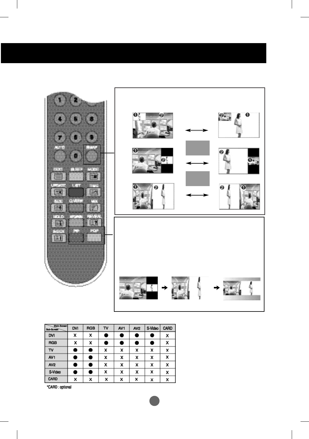
SWAP function Button
To switch the main-screen and sub-screen in
PIP/POP/PBP mode.
Number buttons
Able to directly select and change channel.
MENU
Use this button to enter the On Screen Display menu.
EXIT
Use this button to exit the On Screen Display menu.
*/SSM
(Sound Status Memory)
Use this button to select the sound tone.
Press repeatedly to select Flat, Music, Movie,
Speech, User
sound tone.
A10
ENGLISH
A10
Remote Control
SLEEP : SLEEP Timer
You can set a time period after which the
TV / AV1 / AV2 / S-Video should switch itself to
standby. Press the key repeatedly to select the
number of minutes.
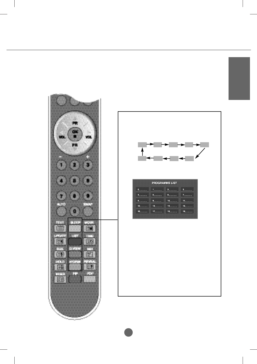
LIST : Programme list
To display the programme list (0~ 99).
Q.VIEW : QUICK VIEW Button
To display the previously selected TV channel.
* Favourite Program On : Rotate Favourite channel
APC / PSM
Button
Press repeatedly to select Dynamic, Standard, Mild,
Game, User or Dynamic picture mode. This function is not
supported in PC mode.
Note: TV channels displayed in blue have been
setup to be skipped in the Programme Edit
menu
10 20 30 60
240 180 120 90
OFF
A11
Name and Function of the Parts
2.
PIP (Picture in Picture)
Button
The sub-screen is changed in the order shown below.
: SMALL -> MIDDLE -> LARGE -> OFF
3. POP (Picture out Picture) Button
The sub-screen moves to the next mode whenever you press
this button.
: POP ON -> PBP(FULL) -> PBP(4:3) -> OFF
Remote Control - PIP/POP/PBP function
<Table of PIP/POP/PBP Function Support>
SWAP
SWAP
When 'Input Signal 1' comes on in the main
screen, only 'Input Signal 2' can be
displayed on the sub-screen. On the
contrary, if the main screen displays 'Input
Signal 2', the sub-screen can display 'Input
Signal 1' only. You can swap 'Input Signal
1' and 'Input Signal 2' using the SWAP
button.
1. Swap Button
You can swap the main screen and the sub-screen when the
PIP/POP/PBP function is used.
PIP
POP
PBP
POP ON PBP (FULL) PBP (4:3)
A12
ENGLISH
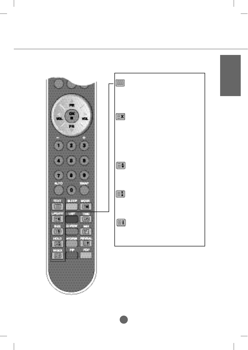
Remote Control - Using the Teletext function
TEXT
To select the teletext on or off. The main index
page or the last selected page appears on the
screen together with an information headline and
an option line at the bottom of the screen.
UPDATE
Press the button to appear the TV programme. At
the top of screen indicates that you are still in the
teletext mode. Before interrupting teletext, you
may select a page number. When the page has
been found, the information line appears briefly
on your screen. Press the button again to
reappear teletext.
SIZE
Press the button repeatedly to display the upper
part, the lower part and then to return to the
normal page size.
HOLD
Press the button to stop the automatic rotating of
the subpages. Press the button again to continue
the automatic rotating again.
INDEX
To display the main index.
A13
Remote Control - Using the Teletext function
Name and Function of the Parts
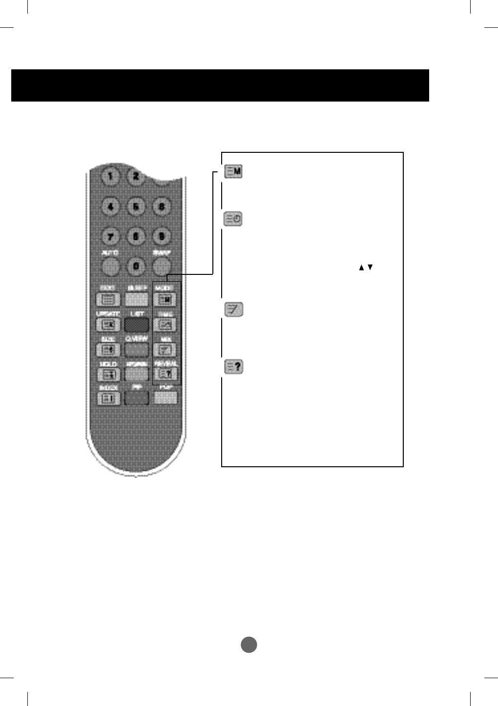
MODE
The mode will be switched in the Teletext
mode.
TIME
press this button to select a sub-page number.
The sub-page number is displayed at the
bottom of the screen. To hold or change the
sub page, press the RED/GREEN, or
NUMBER buttons. Press again to exit this
function.
MIX
Display the teletext pages superimposed on
the TV picture. To switch the TV picture off
press this button again.
REVEAL
Press the button to reveal/conceal the hidden
information, such as solutions to riddles and
puzzles. Press this button again to remove the
information from the display.
A14
ENGLISHENGLISH
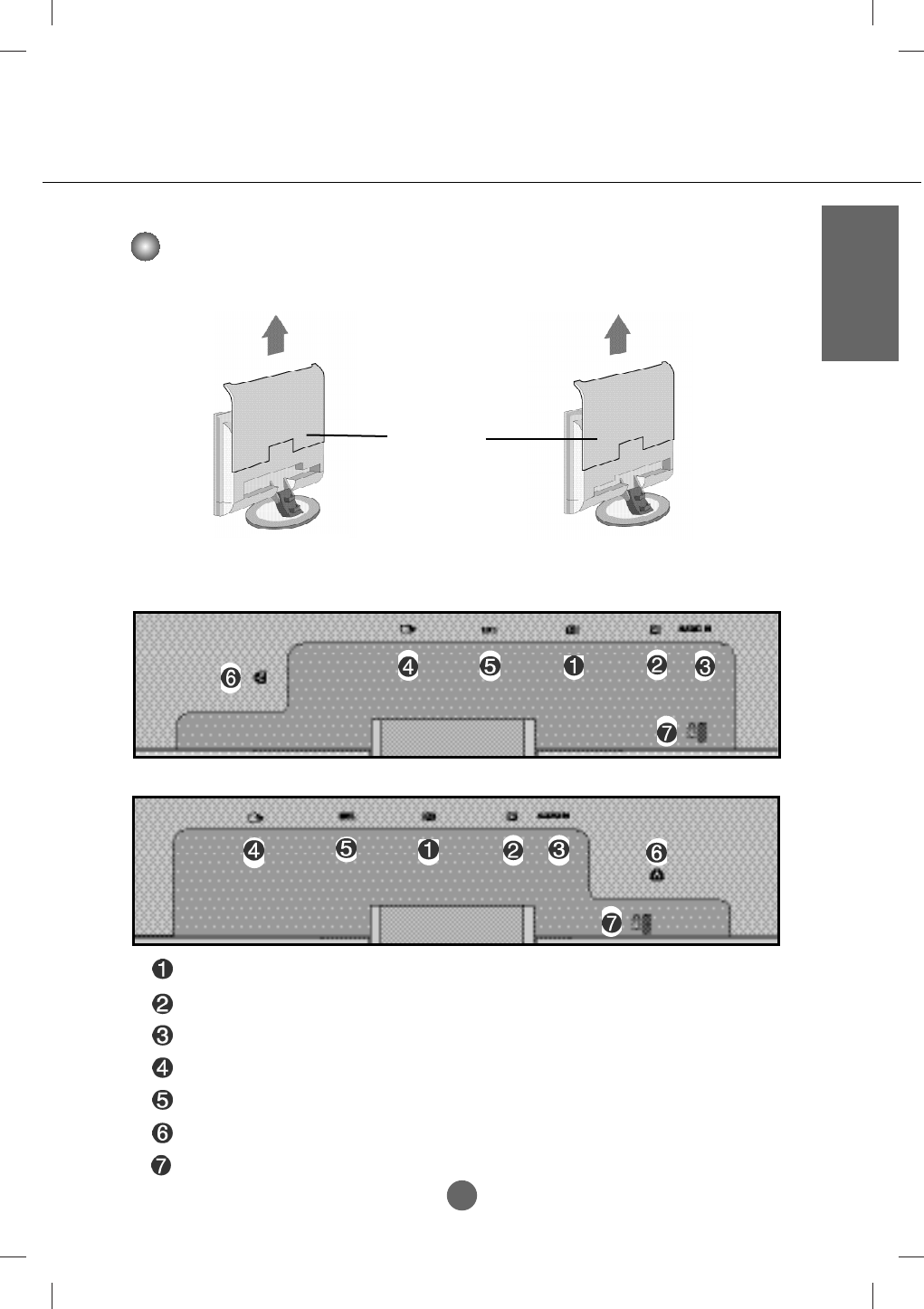
Rear View
DVI Signal Connector
DSUB Analogue Signal Connector
Audio Jack :Connect to the jack in the PC sound card.
SCART Input/Output Terminal : Connect the SCART CABLE
TV Tuner Jack: Connect the antenna.
Power Cord Connector : Connect the power cord.
Theft prevention locking device
20.1 inch
17 inch
First, pull out the back cap attached to the rear of the product to detach, as shown.
Back Cap
- Open the back cap before
you install the product.
20.1 inch 17 inch
A15
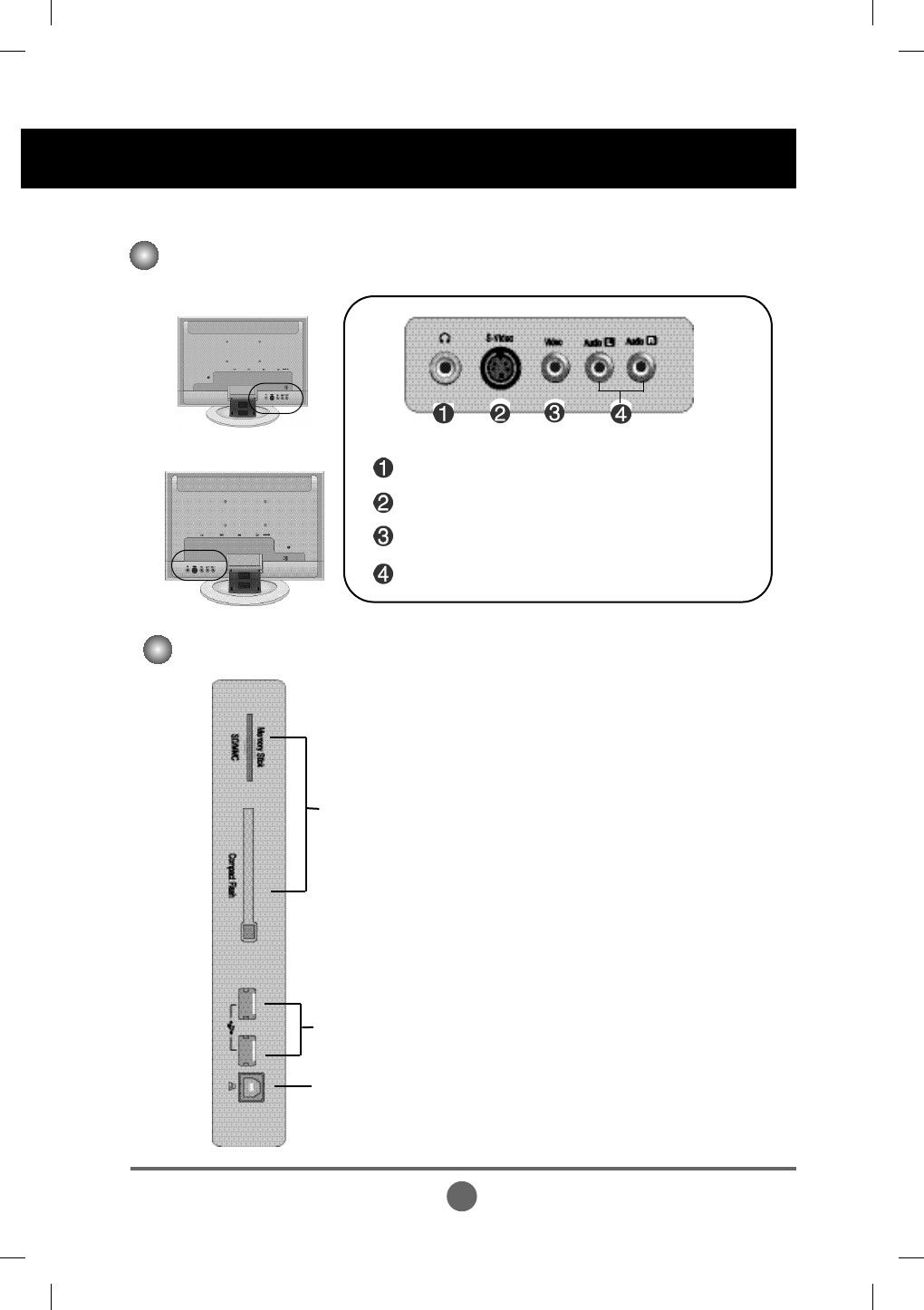
Rear View
Headphone/Earphone Connection Terminal
S-Video Input Terminal
AV Input Terminal (Audio)
Video(CVBS) Input Terminal
USB downstream Port
USB upstream Port
Card Reader
Side View (Optional-20.1 inch)
20.1 inch
17 inch
Name and Function of the Parts
A16
ENGLISH
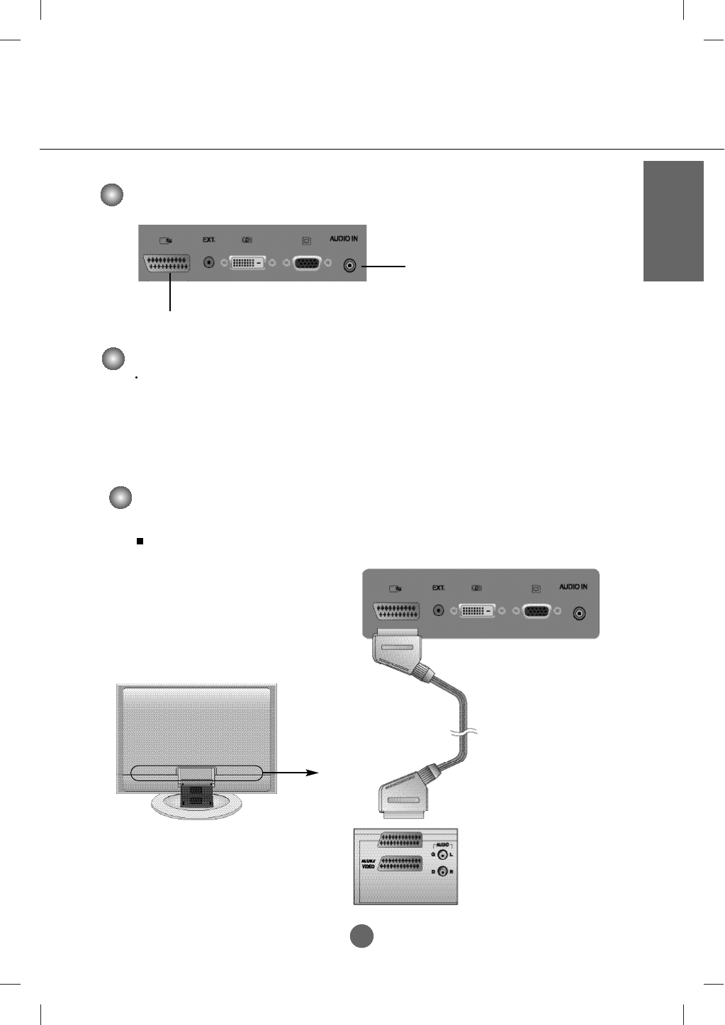
Sound card Connection Terminal Input Terminal
PC Audio Input Terminal
- Connect the audio cable to the
LINE OUT jack in the PC sound card.
Connect the SCART CABLE
Make sure to check the sound card connection terminal in the PC before connecting to the product.
If the PC sound card supports both Speaker Out and Line Out, change it to Line Out by setting the jumper
or the PC application. (For more details, refer to the sound card user’s manual.)
- Speaker Out : The terminal connected to the speaker that is not equipped with an amplifier.
- *Line Out : The terminal connected to the speaker equipped with an amplifier.
If Audio Out in the PC sound card has only Speaker Out, reduce the PC volume. This product is integrated
with an amplifier.
Connecting the sound card output terminal
Connect to the external device if you record the broadcasting.
When you set the input signal of the main screen as 'TV', you can transmit the signal that you're watching to
the Scart output terminal.
TV Output Terminal
SCART Cable
<When connecting SCART cable>
Product
A17
Connecting to External Devices
A17
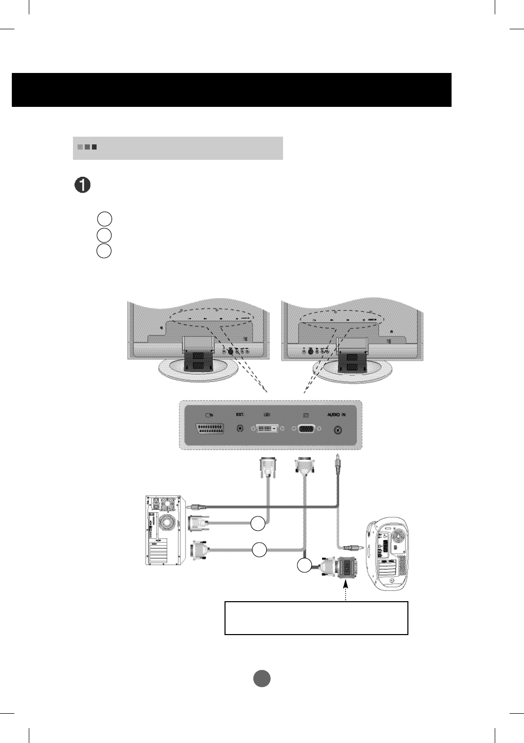
When Connecting to your PC
First of all, see if the computer, product and the peripherals are turned off. Then,
connect the signal input cable and Audio cable.
When connecting with the DVI-D signal input cable.
When connecting with the D-SUB signal input cable. (IBM compatible PC)
When connecting with the D-SUB signal input cable. (Macintosh)
PC
Rear side of the product.
B
A
B
A
MAC
Macintosh Adapter (Optional)
Use the standard Macintosh adapter since an incompatible
adaptor is available in the market. (Different signaling system)
C
C
20.1 inch
17 inch
Audio cable
A18
ENGLISH
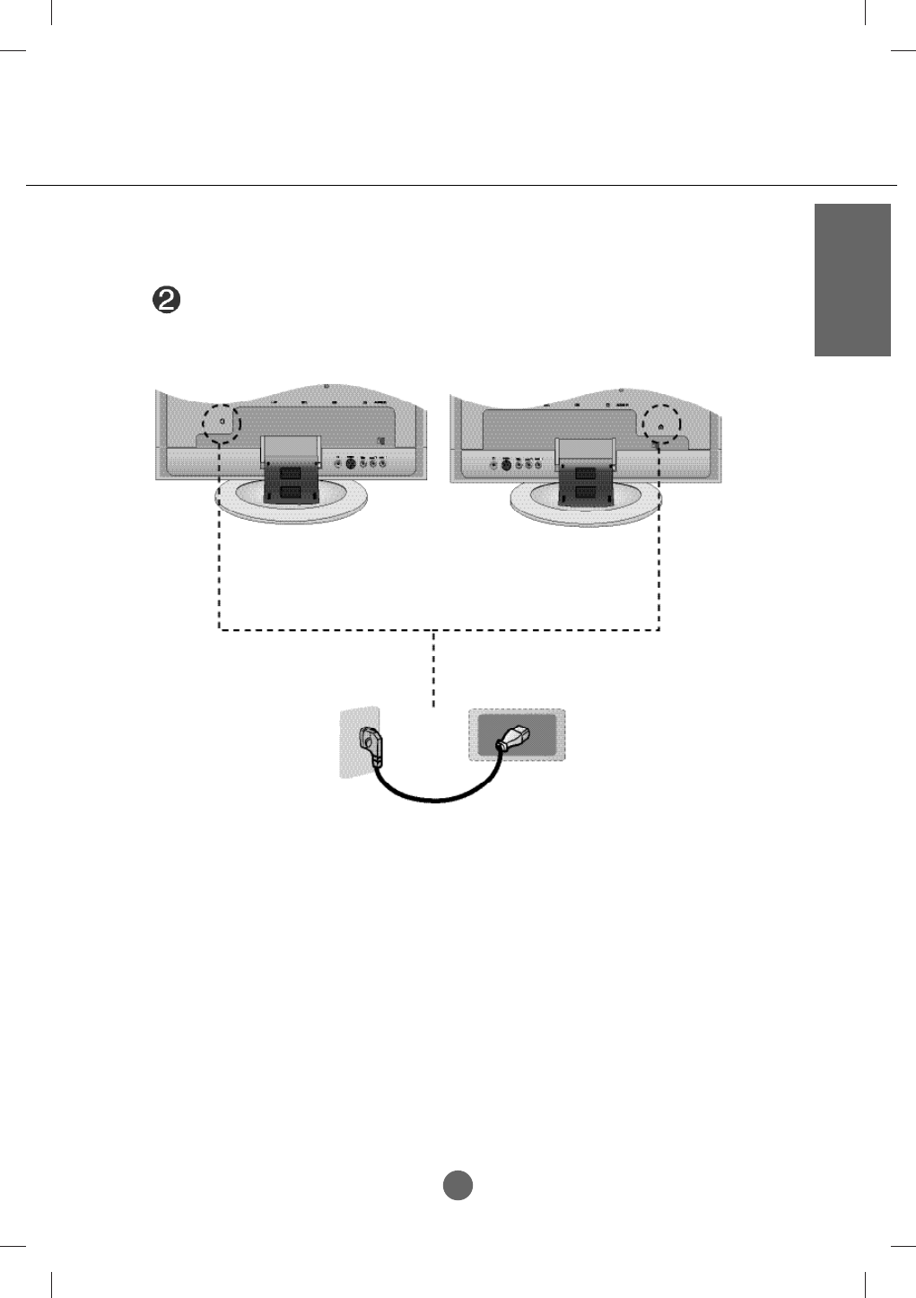
Rear side of the product.
* When connecting to a
wall outlet.
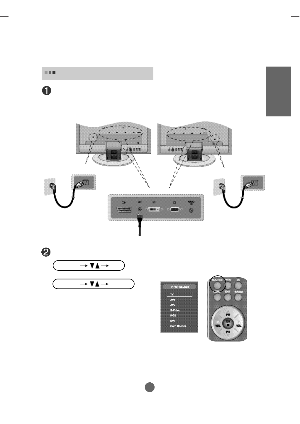
Connect the power cord.
20.1 inch
17 inch
A19
Connecting to External Devices
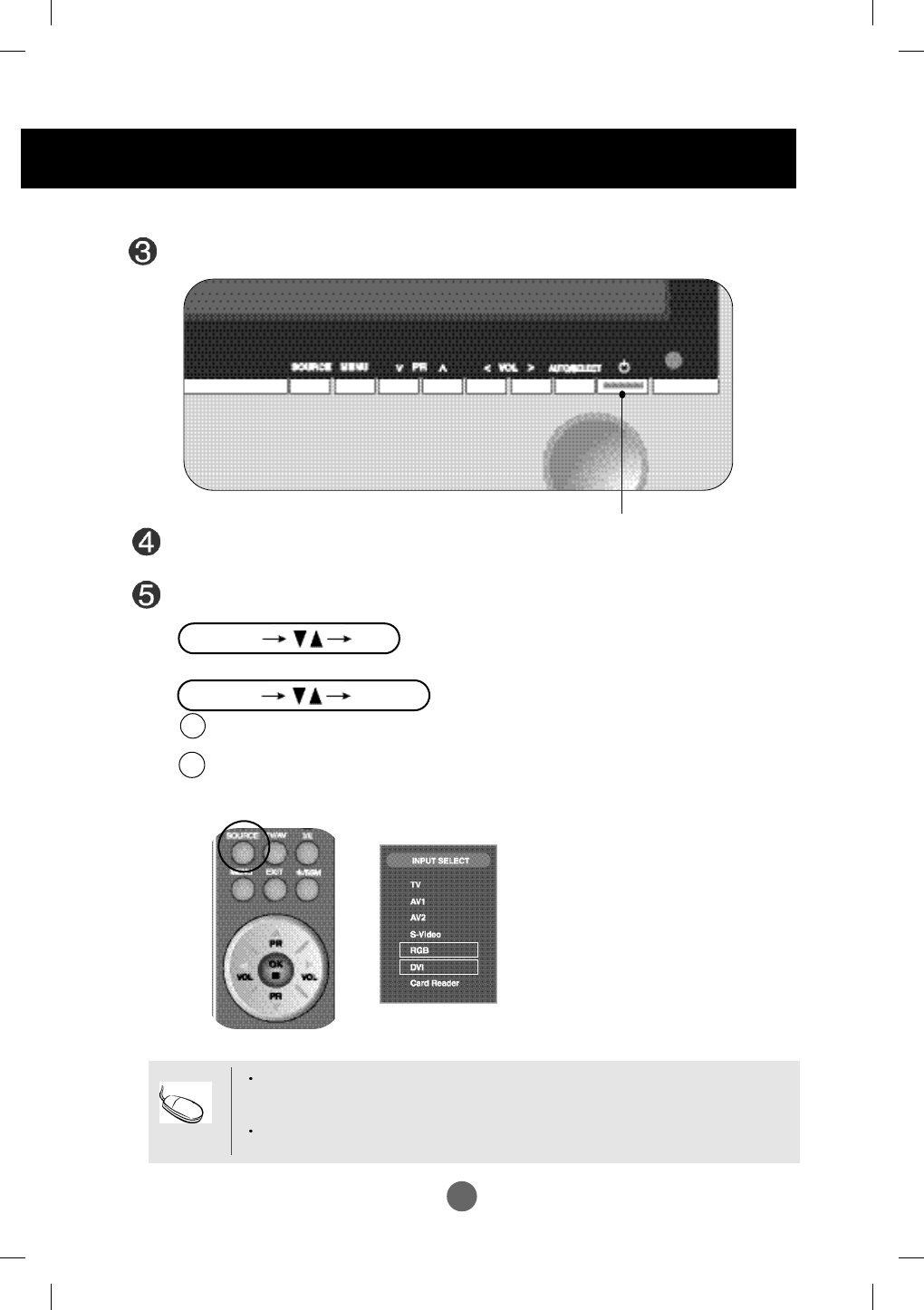
When connecting with a DVI signal input cable.
• Select DVI : DVI-D digital signal.
When connecting with a D-SUB signal input cable.
• Select RGB:
D-SUB
analog signal
Turn on power by pressing the power button on the product.
Turn on the PC.
Select an input signal.
Press the SOURCE button on the remote control to select the input signal.
Or, press the SOURCE button at the front side of the product.
B
A
Power button
How to connect to two computers.
Connect the signal cables (DVI and RGB) to each computer.
Press the SOURCE button in a remote control to select the computer to use.
Directly connect to a grounded power outlet on the wall or a power bar with a ground
wire.
Note
* Card Reader : Optional
*
SOURCE SELECT
SOURCE OK
A20
ENGLISH
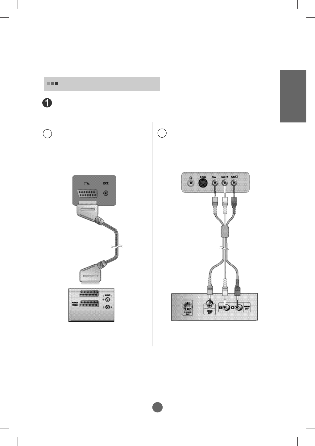
Connect the video cable as shown in the below figure and then connect the power cord.
(See page A17)
When watching Video / DVD
When connecting with an RCA cable.
•
Connect the input terminal with a proper colour
match. (Video – Yellow, Sound (left) – White,
Sound (right) – Red)
B
Red
White
Yellow
RCA Cable
(Not included)
R
W
Y
SCART Cable (Not included)
When connecting with an SCART cable.
Rear side of the Product
A
Rear side of the Product
Video / DVD
Video / DVD
A21
Connecting to External Devices
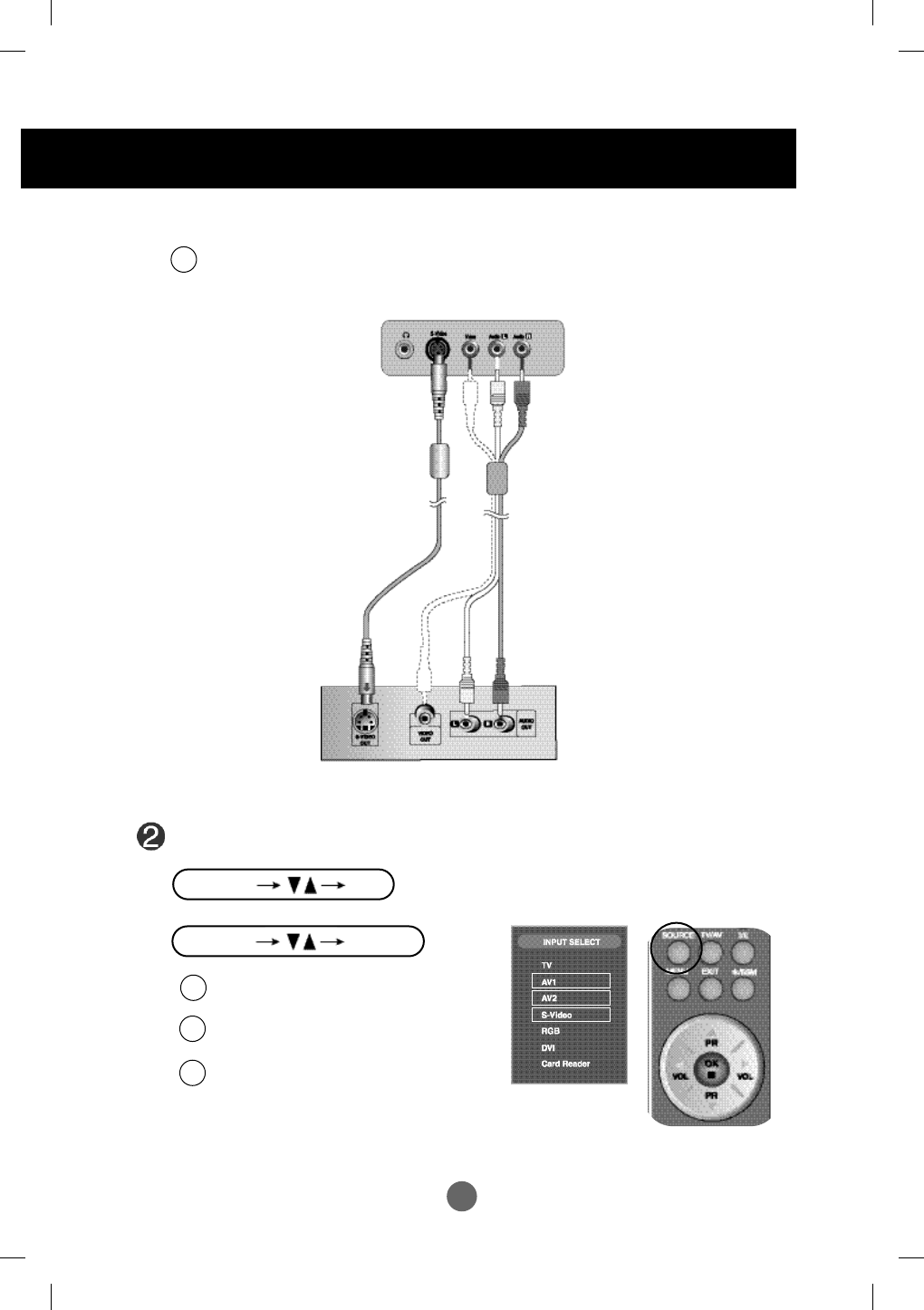
Select an input signal.
Press the SOURCE button on the remote control to select the input signal.
Or, press the SOURCE button at the front side of the product.
When connecting with a SCART cable.
•
Select AV1 (Video)
When connecting with a RCA cable.
•
Select AV2 (Video)
When connecting with a S-Video cable.
•
S-Video
B
C
A
When connecting with an S-Video cable.
•
Connect to the S-Video input terminal to watch high image quality movies.
RCA Cable
(Not included)
S-Video Cable
(Not included)
Video / DVD
Rear side of the Product
C
* Card Reader : Optional
*
Red
White
R
W
SOURCE SELECT
SOURCE OK
A22
ENGLISH
Rear side of the Product
Antenna Cable
(Not Included)
•
Select TV
Select an input signal.
Press the SOURCE button on the remote control to select the input signal.
Or, press the SOURCE button at the front side of the product.
See if the antenna cable is connected at the rear side of the product and
then, connect the power cord.
When watching TV
20.1 inch
17 inch
* Card Reader : Optional
*
SOURCE SELECT
SOURCE OK
A23
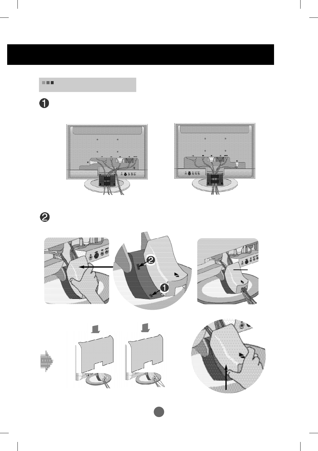
To arrange the cables
Connect the signal input cable and the audio cable to use in order to arrange the
power cord, D-sub cable and DVI-D cable as shown in the following figure.
Connect the cable cap according to the steps shown in the following figure.
Cable Cap
20.1 inch
17 inch
To remove the cable cap, hold
and pull forward its bottom.
Connecting to External Devices
A24
ENGLISH
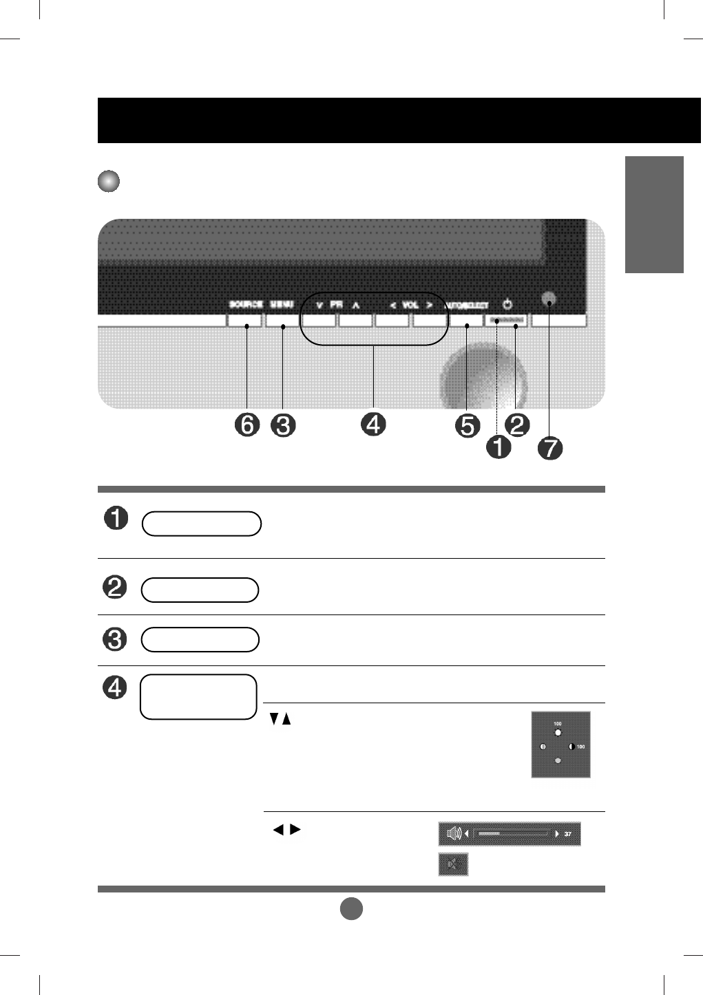
Name of the Buttons in the Screen Adjustment Unit
• Press the button to turn on the power. Press the button again to turn it off.
• This indicator lights up blue when the display operates normally(On
Mode). If the display is in sleep (Energy Saving) mode, this indicator
colour changes to amber.
• Adjust the volume.
• Use this button to directly control
brightness and contrast of the PC signal
(RGB, DVI)
• Use this button to control the channel for
the TV signal.
• Use this button to show/hide the OSD (On Screen Display) menu screen.
•
Use the button to select an icon or adjust the setting in the OSD screen.
Power LED
Power Button
MENU Button
OSD Select /
Adjust Button
Selecting and Adjusting the Screen
A25
Selecting and Adjusting the Screen
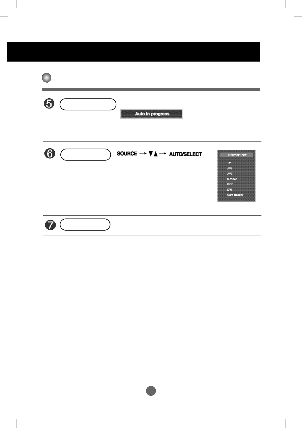
Name of the Buttons in the Screen Adjustment Unit
[For PC Analogue signal]
[For AV1, AV2, S-Video]
• The current signal and mode information will be displayed.
AUTO/SELECT Button
TV Television
AV1 SCART
AV2 Composite video
S-Video SeparateVideo
RGB D-SUB analog signal
DVI DVI digital signal
Card Reader Media Manager
• Select the input signal
SOURCE Button
• The unit that receives the signal from the remote control.
* Card Reader : Optional
*
IR Receiver
A26
ENGLISH
OSD (On Screen Display) Screen Tracking Order
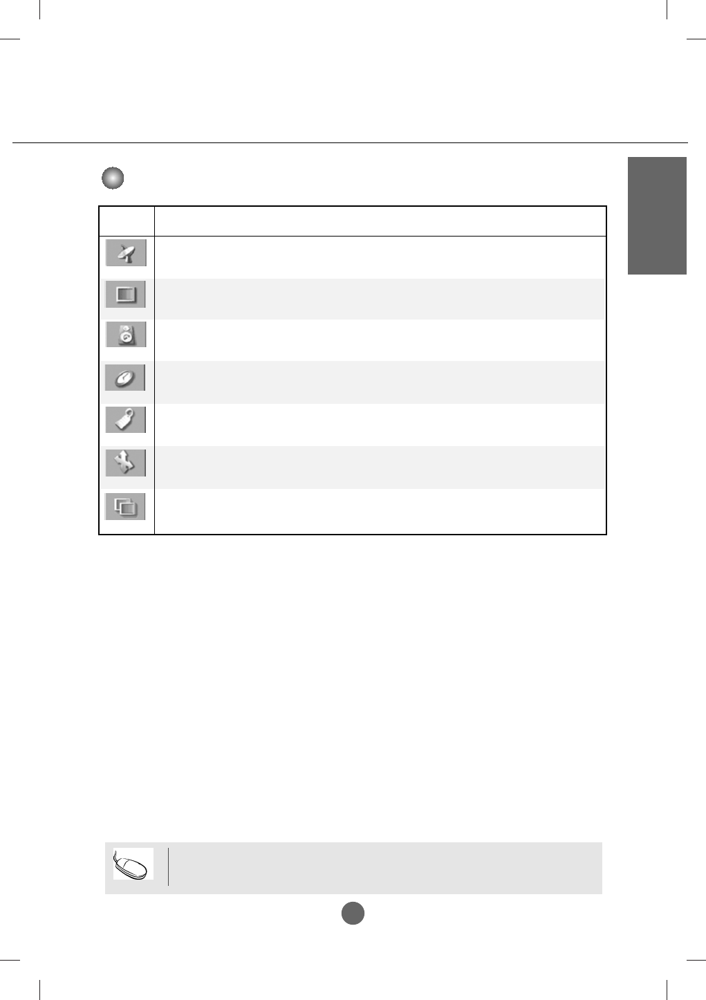
Icon Function Description
STATION
PICTURE
SOUND
TIMER
Adjusts the timer function.
Adjusting Screen CLOCK/PHASE and Position
Adjusts the audio function.
Adjusts screen brightness, contrast and colour that you prefer.
Set/Selects the channel.
Note
OSD(On Screen Display)
The OSD function enables you to adjust the screen status conveniently since it provides
graphical presentation.
SPECIAL
Adjusts the screen status according to the circumstances.
PIP/POP/PBP
Adjusts PIP/POP/PBP mode function.
SCREEN
A27
Selecting and Adjusting the Screen
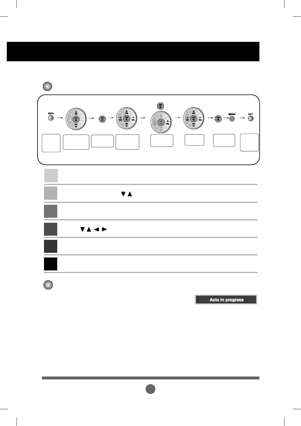
How to adjust the OSD (On Screen Display) screen.
•
Use the remote control to adjust the OSD screen.
How to adjust the screen automatically.
You need to adjust the screen display when connecting the product to a
new computer or changing the mode. Refer to the following section to
set an optimal product screen.
Press the AUTO/SELECT button (AUTO button in a remote control) in
the PC analog signal. Then, an optimal screen status will be selected
that fits into the current mode.
If adjustment is not satisfactory, you need to adjust screen position,
clock and phase in the OSD menu.
Pops up
the menu
screen
Move where
you want to
adjust
Select a
menu icon
Adjust the
status
Save/Select
adjustment
Exit from
the menu
screen.
Press the MENU Button, then the main menu of the OSD appears.
To access a control, use the Buttons.
When the icon you want becomes highlighted, press the OK Button.
Use the Buttons to adjust the item to the desired level.
Accept the changes by pressing the OK Button and MENU Button.
Exit the OSD by pressing the EXIT Button.
1
2
3
4
5
6
Move where
you want to
adjust
Select a
menu icon
or
A28
ENGLISH
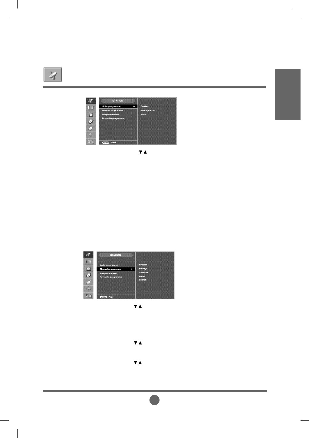
Set/Selects the channel when using the TV
Press the buttons to select the TV system of the country or part of
the world from where you want to receive the TV channels.
If you want to receive 'SECAM L' channel, change the SYSTEM menu to
'L' before launching an automatic search.
L: SECAM L/L (France)
BG : PAL B/G, SECAM B/G (Europe/East Europe)
I : PAL I/II (U.K/Ireland)
DK : PAL D/K, SECAM D/K (East Europe)
To select a programme number or enter the programe number with the
number buttons from where you want to start searching for new channels.
If you want to keep the channels 1 to 10 stored earlier, enter programe
number 11. Your TV search for new channels from number 11 onwards.
Press OK button to start automatic programming. all available TV
channels are searched for and stored automatically. To stop auto
programming, press the MENU or EXIT button. When auto programming
is completed, the programme list menu appears.
System
Storage
from
Start
Auto programme
Press the buttons to select the TV system of the country or part of
the world from where you want to receive the TV channels.
L: SECAM L/L (France)
BG : PAL B/G, SECAM B/G (Europe/East Europe)
I : PAL I/II (U.K/Ireland)
DK : PAL D/K, SECAM D/K (East Europe)
Press the buttons to select the channel number or enter the
programme number with the number buttons in where you want to store
channel.
Press the buttons to select V/UHF for aerial channels or CABLE for
cable channels.If you know the C-(01~69) or S-channel number(01~47),
enter it directly with the digit buttons 0 to 9.
To select the channel reception type. : V/UHF / CABLE
System
Storage
Channel
Manual programme
To change the channel.
(Change each item in Manual
Program and press the "Menu"
button to save the settings)
A29
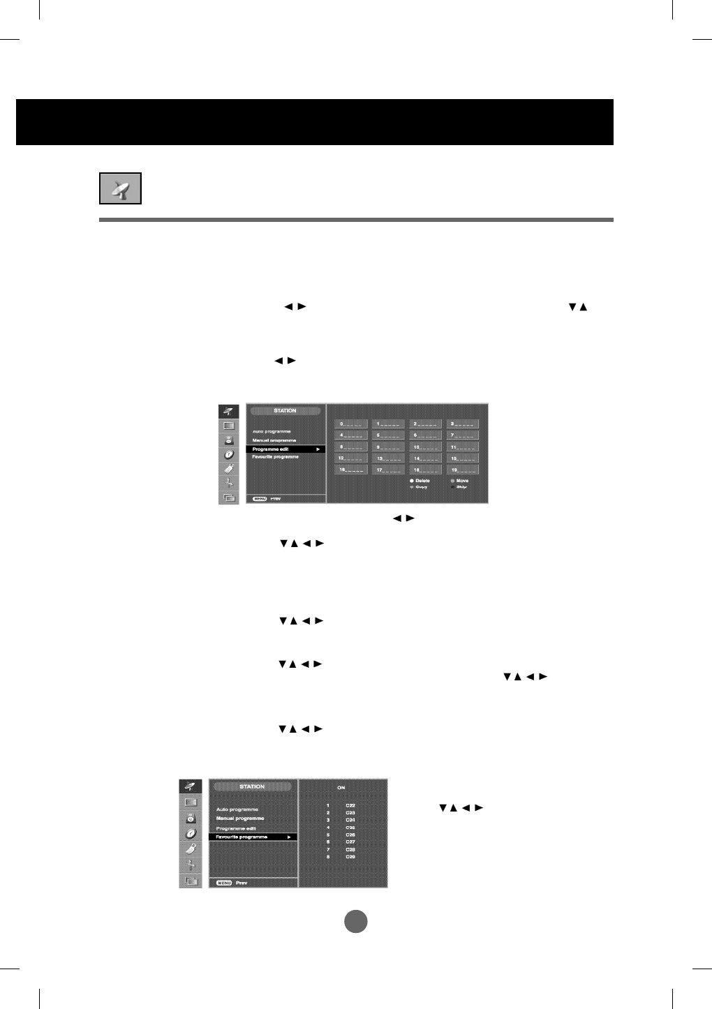
Selecting and Adjusting the Screen
Press the buttons to select a TV channel to be deleted.
-> Press the red key on the remote control -> The background colour of the
selected channel will change to red.
Press the Delete button one more time to delete the selected channel.
All the following channels are shifted up one position.
Press the buttons to select a TV channel to be copyed. ->
Press the green key on the remote control. All the following channel
numbers are shifted down one position.
Press the buttons to select a channel number to be moved. ->
Press the yellow key on the remote control. -> Press the
buttons to move the TV channel to the desired channel number. ->
Press the yellow key again to release this function.
Press the buttons to select a channel number to be skipped. ->
Press the blue key on the remote control. The skipped TV channel is
displayed in blue.
To adjust the Edit submenu function, Press the OK --> button on the remote control
Delete
Copy
Move
Skip
To see the assigned channel name.
It is possible to change the name stored in the memory or to assign a name
to a TV channel which has not yet been entered. A name with up 5 letters or
numbers can be given to the programme numbers 0 to 99.
Press the buttons to move cursor to be changed. -> Press the
buttons to select a character.(space, number 0~9, and alphabet A~Z, +,-) ->
Press OK button and MENUbutton).
Use the buttons to search next channel backward or foreward
direction.
Name
Search
Programme edit
Set/Selects the channel when using the TV
Favourite
programme
This function lets you select your favourite
programmes directly. (8 channel)
Press the buttons to select a
channel number.
* Q.VIEW button(remote control) :
Favourite channel Rotation
A30
ENGLISH
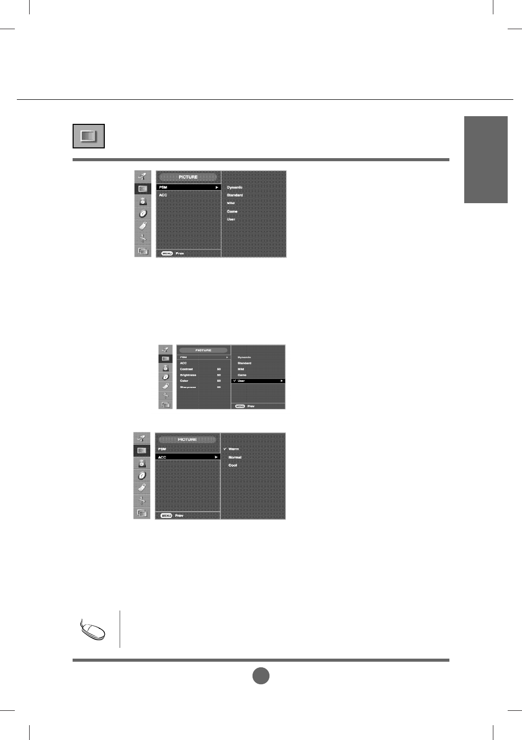
Adjusting Screen Colour
Contrast
To adjust the contrast of the screen.
Brightness
To adjust the brightness of the screen.
Colour
To adjust the colour to desired level.
Sharpness
To adjust the cleaness of the screen.
Tint
To adjust the tint to desired level. (only 60Hz signal)
TV/AV1/AV2/S-Video input only
The PSM function automatically adjusts the screen image quality
depending on the AV/TV usage environment.
• Dynamic : Select this option to display with a sharp image.
• Standard : The most general and natural screen display status.
• Mild : Select this option to display with a mild image.
• Game : Select this option to enjoy dynamic image when playing a game.
• User : Select this option to use the user-defined settings.
Selecting a factory setting colour set.
• Warm : Slightly reddish white.
• Normal : Slightly bluish white.
• Cool : Slightly purplish white.
PSM
ACC
Note
If the PSM' setting in the Picture menu is set to Dynamic, Standard, Mild or Game
the subsequent menus will be automatically set.
A31
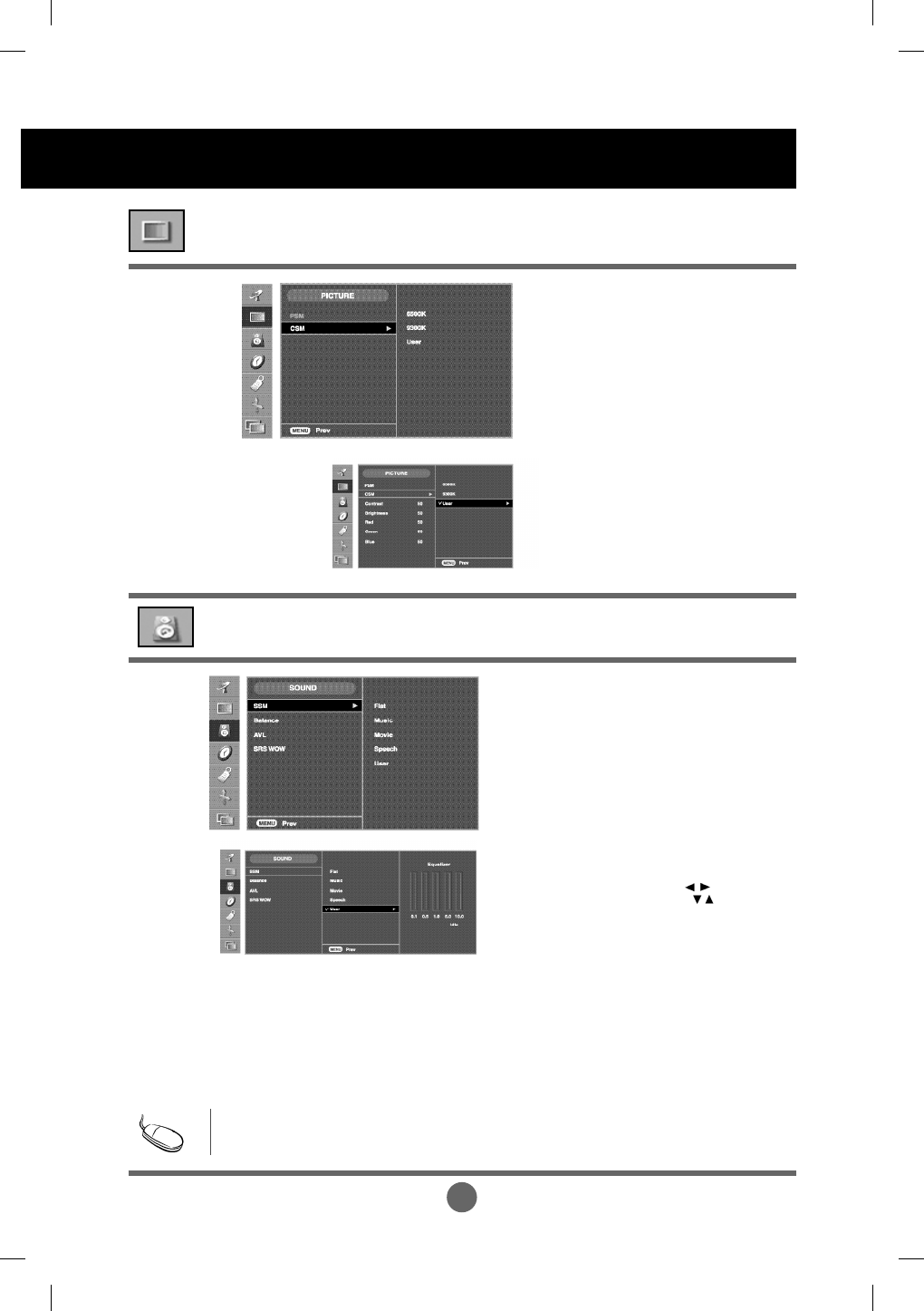
Selecting and Adjusting the Screen
Contrast
To adjust the contrast of the screen.
Brightness
To adjust the brightness of the screen.
Red / Green / Blue
Set your own colour levels.
RGB / DVI input only
• 6500K/9300K
Selecting a factory setting colour set.
6500K: Slightly reddish white.
9300K: Slightly bluish white.
• User : Select this option to use
the user-defined settings.
CSM
Adjusting Screen Colour
The best sound tone quality will be selected automatically
depending on the video type that you're currently watching.
SSM
Adjusting the audio function
Note
When connected to your computer and the 'SSM' setting in the audio menu is one of Flat, Movie,
Music or Speech, the available menus are Balance, SRS WOW .
Use this function to balance sound from the left and right speakers.
To adjust uneven sound volumes across all channels or signals automatically to the most
appropriate level. To use this feature, select ON. (It is adjustble to the TV input signal only.)
Set the SRS WOW menu on.
The SRS WOW function plays back the mono or stereo sound input with the dynamic surround
effects. It will provide rich and profound sound tone. If you set the SRS WOW on, SSM setting
can not be adjusted.
Balance
AVL
SRS WOW
• Flat
The most commanding and natural audio.
• Music
Select this option to enjoy the original sound when listening
to the music.
• Movie
Select this option to enjoy sublime sound.
• Speech
Select this option to watch sports broadcasting.
• User
Select this option to use the user-defined audio settings.
1) Select a sound band by pressing the button.
2) Make appropriate sound level with the button.
3) Press the OK button to stroe it for sound User.
A32
ENGLISH
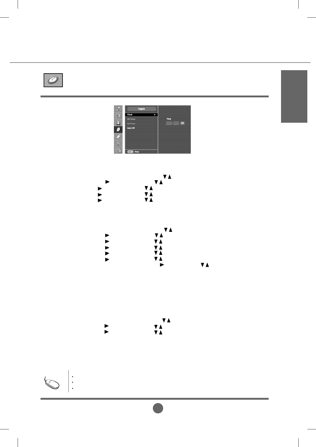
Clock
Adjusting the timer function
(Setting is available, however, operation is only allowed upon TV/AV1/AV2/S-Video input)
The off timer automatically switches the set to standby at the pre-set time.
1) Press the MENU button and then use
button to select the TIMER menu.
2) Press the button and then use
button to select Off Timer or On Timer.
3) Press the button and then use
button to set the hour(01~12).
4) Press the button and then use
button to set the minutes(00~59).
5) Press the button and then use
button to set the morning(AM) or afternoon(PM).
6) Press the button and then use
button to select On or Off.
7) Only ON Timer function; Press the button and then
button to adjust volume level
and program number
.
8) Press the OK or MENU button to save.
Off / On Timer
Auto Off
This function is used to set up of current time.
You must set the time correctly before using on/off timer function.
1) Press the MENU button and then use
button to select the TIMER menu.
2) Press the button and then use
button to select the Clock menu.
3
) Press
button and then use button to set the hour(01~12).
4
) Press
button and then use button to set the minutes(00~59).
5
) Press
button and then use button to set the morning(AM) or afternoon(PM).
The default value is __:__.
(Setting is available, however, operation is only allowed upon TV/AV1/AV2/S-Video input)
If Auto Off is active and there is no input signal, Make sure there is no remote control input.
the TV swithchs to Stanby mode automatically after 10 minutes.
1) Press the MENU button and then use
button to select the TIMER menu.
2) Press the button and then use
button to select the
Auto
Off menu.
3) Press the button and then use
button to select On or Off.
4) Press the OK/MENU button to save .
In the event of power interruption (disconnection or power failure), the clock must be reset.
Once the on or off time is set, these functions operate daily at the preset time.
The set must be in standby mode for the On timer to work.
Note
A33
Selecting and Adjusting the Screen
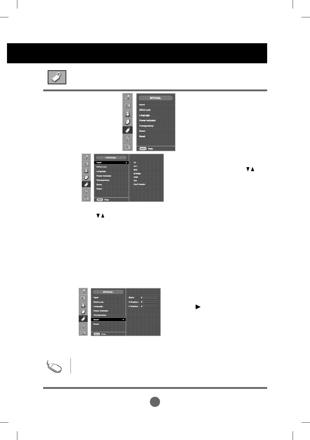
Selecting the SPECIAL
Language
Power
Indicator
To choose the language in which the control names are displayed.
Use this function to set the power indicator on the front side of the product to ON or
OFF.
Use this function to zoom in the screen.
When you turn the product off and on again,
the default screen size will be restored.
Press the button to display the
submenu for Zoom.
Transparency
Zoom
Use this function to reset the product to the factory default. However, language selection will not
be initialized. ( PICTURE, SOUND, TIMER, SPECIALmenu)
Reset
* If the zooming value is set to '0', vertical and
horizontal positioning cannot be adjusted.
Note
the Zoom menu will be disabled if the screen size is not Full or PIP/POP/PBP is in use.
Use the buttons to select ON or OFF. The TV can be set up so that it can only be used
with the remote control. This feature can prevent unauthorized viewing.
In order to lock the OSD screen adjustment, set the Child lock tab to the 'on' position.
In order to unlock it, do the following :
* Push the MENU button on the remote control and set Child lock to the 'off' position.
Child lock
If you press the button once, the following
Input Signal Window will appear. Select
the signal type you want using the
button.
Input
To adjust the transparency of the OSD menu screen.
* Card Reader : Optional
*
A34
ENGLISH
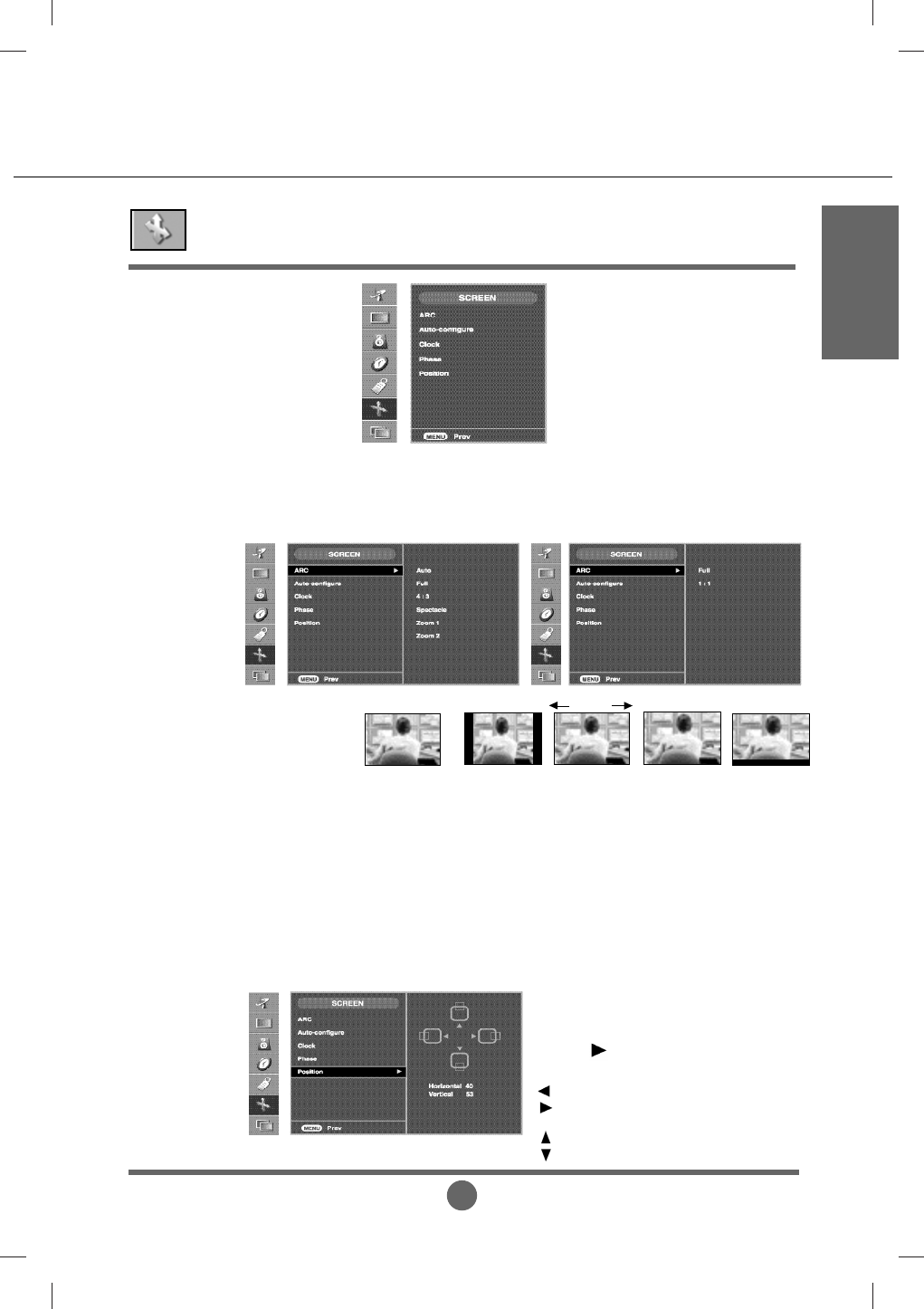
Adjusting Screen CLOCK/PHASE and Position
This function is suitable for analogue singnal input only. This button is for the automatic
adjustment of the screen position, clock and phase.
ARC
Auto-
Configure
This function is suitable for analogue singnal input only. To minimize any vertical bars or
stripes visible on the screen background. The horizontal screen size will also change.
Clock
This function is suitable for analogue singnal input only. To adjust the focus of the
display. This item allows you to remove any horizontal noise and clear or sharpen the
image of characters.
Phase
To select the image size of the screen.
(Auto/Full / 4:3 / Spectacle / Zoom 1 / Zoom 2)
* In only TV/AV1/AV2/S-Video
Position
This function is suitable for analogue
singnal input only. To adjust position of the
screen.
Press the button to display the submenu
for position.
Left
Right Moving the screen position horizontally.
Up
Down Moving the screen position vertically.
* FULL/1:1 in DVI/RGB
Full 4:3 Zoom1 Zoom2
Spectacle
Auto
The screen aspect ratio is
changed according to
broadcasting system
signal.
A35
Selecting and Adjusting the Screen
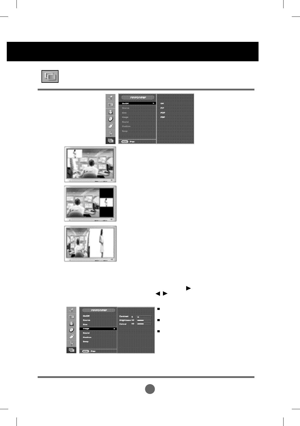
Adjusting PIP/POP/PBP Mode (Multiple Screen) Functions
After selecting PIP/POP/PBP in the PIP
On/Off
menu, the following menu items can be adjusted.
PIP
Source
Size
Image
To select an input signal for PIP/POP/PBP.
To adjust the size of the PIP/PBP screen. (PIP : Small, Medium, Large / PBP : Full, 4:3)
To adjust the image of the PIP/POP/PBP screen; Press the button to display the
submenu for PIP/POP/PBP image. Use the buttons to adjust the item to the desired
level. The items of the sub-menu may vary depending on the type of the source.
Contrast
Adjust PIP/POP/PBP screen contrast.
Brightness
Adjust PIP/POP/PBP screen brightness.
Colour
Adjust the PIP/POP/PBP screen colour. (TV/AV1/AV2/S-Video)
* The sub-menu can differ according to the type of the input signal.
After selecting PIP/POP/PBP in the POP
On/Off
menu, the following menu items can be adjusted.
POP
After selecting PIP/POP/PBP in the PBP
On/Off
menu, the following menu items can be adjusted.
PBP
On/Off
To turn the PIP/POP/PBP sound on/off.
Sound
(To adjust the sub screen)
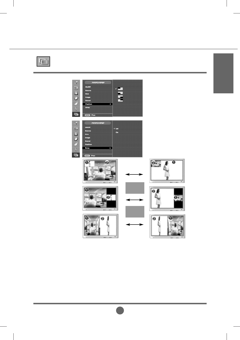
A36
ENGLISH
To adjust the position of PIP screen.
Position
Adjusting PIP/POP/PBP Mode (Multiple Screen) Functions
SWAP
SWAP
PIP
POP
PBP
To switch the main-screen and sub-
screen in PIP/POP/PBP mode.
Swap
A37
• Install the product driver, which is provided with
the product, or download it from the web site.
(http://www.lge.com)
• See if the plug&play function is supported by
referring to the video card user manual.
Did you install the driver?
'Unknown Product' message appears when the product is connected.
• See if the power cord is properly connected to the
outlet.
• See if the power switch is turned on.
• Adjust brightness ( ) and contrast ( ) again.
• If the product is in power saving mode, move the
mouse or press any key.
• The signal from the PC (video card) is out of the
vertical or horizontal frequency range of the
product. Adjust the frequency range by referring
to the Specifications in this manual.
* Maximum resolution
17inch : 1280 x 1024 @60Hz
20.1inch : 1680 x 1050 @60Hz
• The signal cable between PC and product is not
connected. Check the signal cable.
• Press the 'SOURCE' button in the remote control
to check the input signal.
Is the product power cord
connected?
Does the power LED is turned on?
Power is on, power LED is blue but
the screen appears extremely dark.
Does the power LED look amber?
Does the 'Out of Range' message
appear?
Does the 'Check Signal Cable'
message appear?
No image is displayed
Note
• The control locking function prevents unintentional
OSD setting change due to careless usage. To
unlock the controls.You can only set this function
using the remote control.
The “Controls locked” message
appears when pressing local key.
'Controls Locked' message appears.
* Vertical frequency: To enable the user to watch the product display, screen image should be changed tens of times
every second like a fluorescent lamp. The vertical frequency or refresh rate is the times of image display per second.
The unit is Hz.
* Horizontal frequency: The horizontal interval is the time to display one vertical line. When the 1 is divided by
horizontal interval, the number of horizontal lines displayed every second can be tabulated as the horizontal
frequency. The unit is kHz.
Troubleshooting
A38
ENGLISH
The screen image looks abnormal.
• DSUB analog signal – Press the “AUTO” button in
the remote control to automatically select the
optimal screen status that fits into the current
mode. If adjustment is not satisfactory, use the
Position menu in OSD .
• See if the video card resolution and frequency are
supported by the product. If the frequency is out of
range, set to the recommended resolution in the
Control Panel – Display – Setting menu.
• DSUB analog signal – Press the “AUTO” button in
the remote control to automatically select an
optimal screen status that fits into the current
mode. If adjustment is not satisfactory, use the
Clock menu in OSD.
• DSUB analog signal – Press the “AUTO” button in
the remote control to automatically select an
optimal screen status that fits into the current
mode. If adjustment is not satisfactory, use the
Phase menu in OSD.
• See if the Zoom value is set to 0. If it is, you
cannot adjust the H/V Position value.
• If the screen size is not full when connected to the
PC, execute the PIP/POP/PBP to change to full
screen mode.
• See if the TV sound is set to mono. If it is, the
sound will not be displayed.
• You cannot adjust brightness in the PIP/POP/PBP
Screen menu for the sub-screen among
PIP/POP/PBP menus. Therefore, brightness can
be different for the sub-screen.
• The proper input signal is not connected to the
signal port. Connect the signal cable that matches
with the source input signal.
Is the screen position wrong?
Do thin lines appear on the
background screen?
Horizontal noise appears or the
characters look blurred.
Unable to adjust the horizontal /
vertical position in the Zoom menu.
Screen size is automatically adjusted
when connected to the PC.
No sound appears in the TV channel
display window.
Brightness differs in the main and
sub screen when connected to the
PC.
The screen is displayed abnormally.
A39
• Set the number of colours to more than 24 bits
(true colour)
Select Control Panel – Display – Settings
– Colour Table menu in Windows.
• Check the connection status of the signal cable.
Or, re-insert the PC video card.
• Several pixels (red, green, white or black colour)
may appear on the screen, which can be
attributable to the unique characteristics of the
LCD panel. It is not a malfunction of the LCD.
Screen has poor colour resolution
(16 colours).
Screen colour is unstable or mono-
coloured.
Do black spots appear on the
screen?
Screen colour is abnormal.
• See if the audio cable is connected properly.
• Adjust the volume.
• See if the sound is set properly.
• See if the sound is set to On in the PIP/POP/PBP
menu.
• Select the appropriate equalize sound.
• Adjust the volume.
No sound?
No sound is available when the
PIP/POP/PBP mode is engaged.
Sound is too dull.
Sound is too low.
The audio function does not work.
• See if you have selected the proper channel
mode.
• Use the automatic channel setup function.
• See if the TV antenna is properly connected.
The TV signal is not being received.
The TV function does not work.
• If you use a fixed image for a long time, the pixels
may be damaged quickly. Use the screensaver
function.
After-image appears when the
product is turned off.
After-image appears on the product.
Troubleshooting
A40
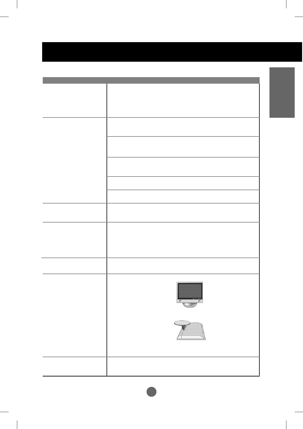
ENGLISH
Specifications
Screen Type 17 inches (434.38mm) TFT (Thin Film Transistor)
LCD (Liquid Crystal Display) Panel
Visible diagonal size: 434.38mm
Pixel Pitch 0.291mm
Max. Resolution D-Sub :1280X1024 @60Hz
DVI-D : 1280X1024 @60Hz
Recommended Resolution
D-SUB : WXGA 1280X768 @60Hz
DVI-D : WXGA 1280X768 @60Hz
Horizontal Frequency D-SUB : 30 - 66 kHz
DVI-D : 30 - 66 kHz
Vertical Frequency 56 - 75 Hz
Synchronization Type Separate/Composite/SOG (Sync On Green)/Digital
15-pin D-Sub type, DVI-D (digital), S-Video,
composite video, Scart, TV
Rated Voltage AC 100-240V~ 50/60Hz 1.0A
Power Consumption On Mode : 70W
Sleep Mode : ≤4W
Off Mode : ≤2W
Tilt Range -5˚~20˚
Tilt Stand Attached
Size (WxLxH)
438.2mm x 241.4 mm x 378.9mm
438.2mm x 139.2 mm x 403.5mm
Weight (excl. package) 7.1 kg (15.6 lbs)
Operational Condition Temperature: 10˚C ~ 35˚C , Humidity: 10% ~ 80%
Storage Condition Temperature: -20˚C ~ 60˚C , Humidity: 5% ~ 95%
LCD Panel
Video Signal
Input Connector
Power
Tilt
Dimension/Weight
Environmental Conditions
[17inches]
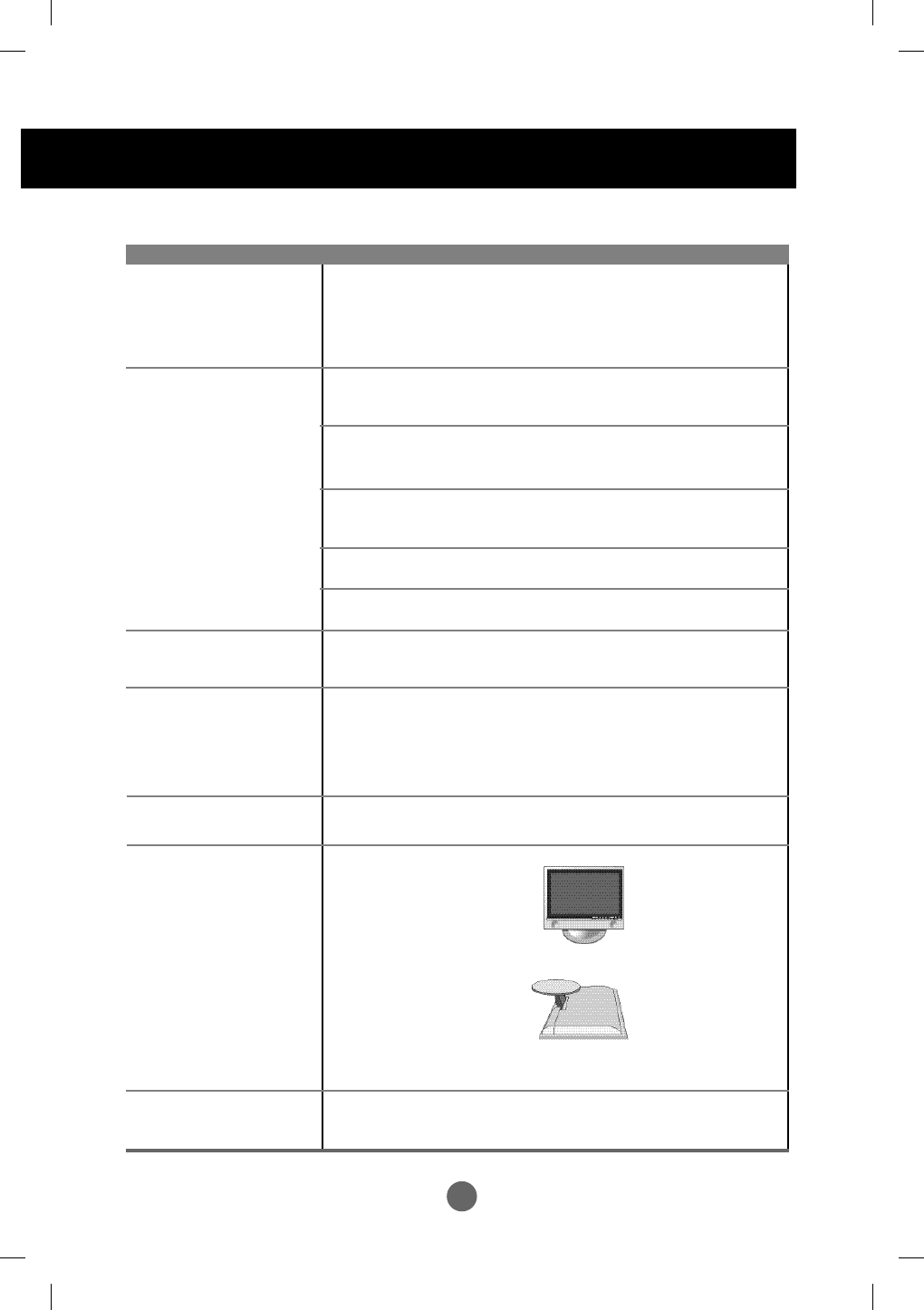
A41
Specifications
Screen Type 20 .1inches (481.84mm) TFT (Thin Film Transistor)
LCD (Liquid Crystal Display) Panel
Visible diagonal size: 481.84mm
Pixel Pitch 0.294mm
Max. Resolution D-SUB : 1680X1050 @60Hz
DVI-D : 1680X1050 @60Hz
Recommended Resolution
D-SUB : WXGA + 1680X1050 @60Hz
DVI-D : WXGA+ 1680X1050 @60Hz
Horizontal Frequency D-SUB : 30 - 83 kHz
DVI-D : 30 - 83 kHz
Vertical Frequency 55 - 75 Hz
Synchronization Type Separate/Composite/SOG (Sync On Green)/Digital
15-pin D-Sub type, DVI-D (digital), S-Video,
composite video, Scart, TV
Rated Voltage AC 100-240V~ 50/60Hz 1.2A
Power Consumption On Mode :74W
Sleep Mode : ≤4W
Off Mode : ≤2W
Tilt Range -5˚~20˚
Tilt Stand Attached
Size (WxLxH)
496.4mm x 241.4mm x 424.1mm
496.4mm x 135.2mm x 448.7mm
Weight (excl. package) 8.2 kg (18.0 lbs)
Operational Condition Temperature: 10˚C ~ 35˚C , Humidity: 10% ~ 80%
Storage Condition Temperature: -20˚C ~ 60˚C , Humidity: 5% ~ 95%
LCD Panel
Video Signal
Input Connector
Power
Tilt
Dimension/Weight
Environmental Conditions
[20.1inches]
A42
ENGLISH
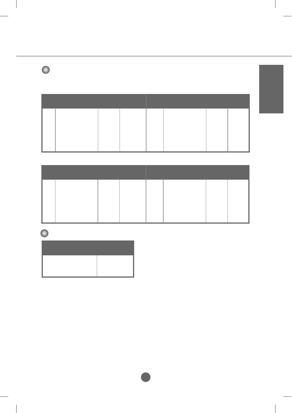
PC Mode – Preset Mode
Power LED
Mode Product
On Mode
Sleep Mode
Off Mode
Blue
Amber
-
Preset mode
Horizontal
Frequency
(kHz)
Vertical
Frequency
(Hz)
Preset mode
Horizontal
Frequency
(kHz)
Vertical
Frequency
(Hz)
1
2
3
4
5
6
7
720 x 400
640 x 480
640 x 480
800 x 600
800 x 600
1024 x 768
1024 x 768
31.468
31.469
37.500
37.897
46.875
48.363
60.123
70
59
75
60
75
60
75
VGA
VGA
VGA
VESA
VESA
VESA
VESA
8
9
10
11
1152 x 864
1280 x 1024
1280 x 1024
1680 x 1050
67.500
63.981
79.976
65.290
VESA
MAC
VESA
VESA
75
60
75
59
[20.1inches]
[17inches]
Preset mode
Horizontal
Frequency
(kHz)
Vertical
Frequency
(Hz)
Preset mode
Horizontal
Frequency
(kHz)
Vertical
Frequency
(Hz)
1
2
3
4
5
6
7
640 x 350
720 x 400
640 x 480
640 x 480
800 x 600
800 x 600
832 x 624
31.468
31.469
31.469
37.500
37.879
46.875
49.725
70
70
59
75
60
75
74
VGA
VGA
VGA
VESA
VESA
VESA
MAC
8
9
10
1024 x 768
1280 x 1024
1280 x 768
48.363
63.981
47.776
VESA
VESA
VESA
60
60
59
A43
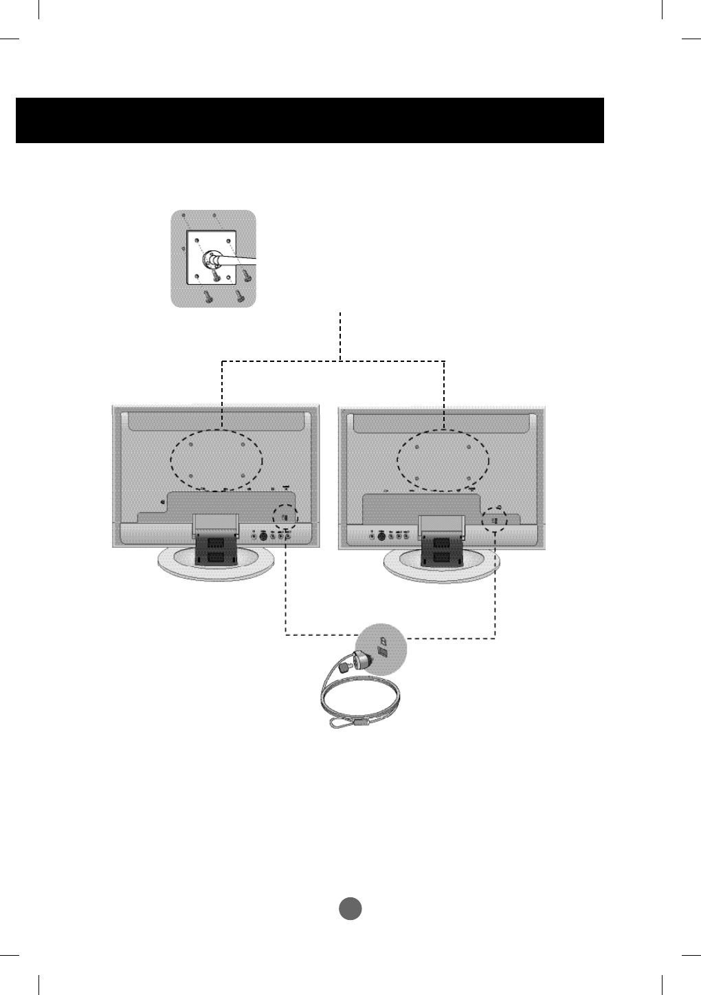
Specifications
Locking Device
Use this locking cable (optional)
toprevent theft.
VESA wall mounting
Connected to another object (stand type and
wall-mounted type. This product accepts a
VESA-compliant mounting interfacepad.optional)
For further information, refer to the VESA Wall
Mounting Instruction Guide.
20.1 inch
17 inch
A44
ENGLISH
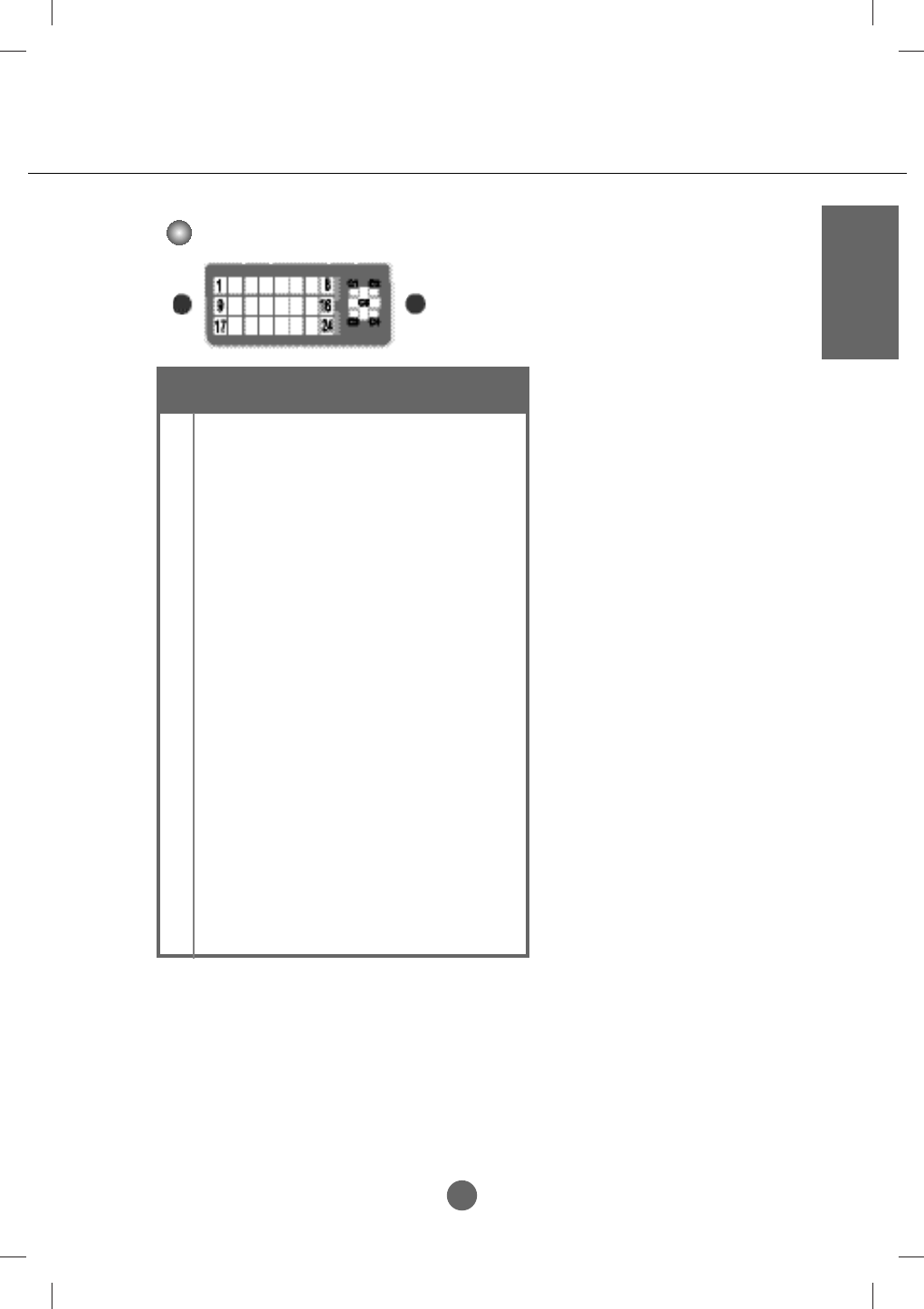
DVI-I
T.M.D.S. (Transition Minimized Differential Signaling)
No. Signal
1
2
3
4
5
6
7
8
9
10
11
12
13
14
15
16
17
18
19
20
21
22
23
24
C1
C2
C3
C4
C5
T. M. D. S. Data 2-
T. M. D. S. Data 2+
T. M. D. S. Data 2/4 Shield
T. M. D. S. Data 4-
T. M. D. S. Data 4+
DDC Clock
DDC Data
Analogue Vertical Synchronization
T. M. D. S. Data 1-
T. M. D. S. Data 1+
T. M. D. S. Data 1/3 Shield
T. M. D. S. Data 3-
T. M. D. S. Data 3+
+5V Power
Grounding (return for +5V, horizontal sync and vertical sync)
Hot Plug Detect
T. M. D. S. Data 0-
T. M. D. S. Data 0+
T. M. D. S. Data 0/5 Shield
T. M. D. S. Data 5-
T. M. D. S. Data 5+
T. M. D. S. Clock Shield
T. M. D. S. Clock+
T. M. D. S. Clock
Analogue Red
Analogue Green
Analogue Blue
Analogue Horizontal Synchronization
Analogue Grounding(return for analogue R,G&B)