LG Electronics USA MU42PZ15 42 inches Plasma Monitor User Manual 1 of 2
LG Electronics USA 42 inches Plasma Monitor 1 of 2
Contents
- 1. User Manual 1 of 2
- 2. User Manual 2 of 2
User Manual 1 of 2
PLASMA MONITOR
ON/OFF INPUT
SELECT VOLUME
P/NO : 3828VA0296J
(NF01DC)
PLASMA MONITOR
Please read this owner’s manual carefully before
operating the Monitor.
Retain it for future reference.
Record model number and serial number of the
Monitor.
See the label attached on the back of the Monitor
and quote this information to your dealer when you
require service.
Model number :
Serial number :
OWNER’S MANUAL
MU-42PZ11/A/B/G/K/S
MU-42PZ15/A/B/G/K/S

FCC NOTICE
•MU-42PZ11/A/B/G/K/S : A Class A digital device
This equipment has been tested and found to comply with the limits for a Class A digital device, pursuant
to Part 15 of the FCC Rules. These limits are designed to provide reasonable protection against harmful
interference when the equipment is operated in a commercial environment. This equipment generates,
uses, and can radiate radio frequency energy and, if not installed and used in accordance with the
instruction manual, may cause harmful interference to radio communications. Operation of this equip-
ment in a residential area is likely to cause harmful interference in which case the user will be required to
correct the interference at his own expense.
WARNING
TO REDUCE THE RISK OF FIRE AND ELECTRIC SHOCK, DO NOT EXPOSE THIS PROD-
UCT TO RAIN OR MOISTURE.
Power supply cord/appliance coupler is used as the main disconnect device, and as
such shall be easily accessible after installation.
Colored dots on the screen
A PDP (Plasma Display Panel), depending on its size, contains from 0.9 to 2.2 million individual
cells. Even with advanced technology it is inevitable that a few defective cells may be found in
the PDP. These defective cells may be visible as colored dots. We continually strive to minimize
the number of defective cells but the existence of a few such defects will not be considered as
sufficient reason for exchange or refund.
Earth wire should be connected.
-If the earth wire is not connected, there is possible a danger of electric shock caused by the
current leakage.
- If grounding methods are not possible, a separate circuit breaker should be employed and
installed by a qualified electrician.
- Do not connect ground to telephone wires, lightning rods or gas pipe.
•MU-42PZ15/A/B/G/K/S : A Class B digital device
This equipment has been tested and found to comply with the limits for a Class B digital device, pursuant
to Part 15 of the FCC Rules. These limits are designed to provide reasonable protection against harmful
interference in a residential installation. This equipment generates, uses and can radiate radio frequency
energy and, if not installed and used in accordance with the instructions, may cause harmful interference
to radio communications. However, there is no guarantee that interference will not occur in a particular
installation. If this equipment does cause harmful interference to radio or television reception, which can
be determined by turning the equipment off and on, the user is encouraged to try to correct the interfer-
ence by one or more of the following measures:
- Reorient or relocate the receiving antenna.
- Increase the separation between the equipment and receiver.
- Connect the equipment into an outlet on a circuit different from that to which the receiver is connected.
- Consult the dealer or an experienced radio/TV technician for help.

Keep this manual
with Monitor for
future easy refer-
ence)
Table of Contents
First step
WARNINGS ..............................................................4
SAFETY INSTRUCTIONS........................................5
Monitor Overview
Front Panel Controls ................................................8
Connection Panel Overview .....................................9
Remote Control Key Functions/Accessories..........10
Monitor Installation .................................................12
Equipment Connections and Setup
VCR Setup..............................................................14
Cable TV Setup ......................................................16
External AV Source Setup......................................17
DVD Setup..............................................................18
DTV Setup..............................................................19
PC Setup ................................................................20
PC Mode Feature Check(Overview) ......................22
PC Mode Adjustments............................................23
Picture In Picture(PIP) function ..............................26
Using the remote control ........................................29
Basic Features Setup and Operation
Turning on the Monitor ...........................................30
Selecting language for the menus..........................31
Checking features...................................................32
Sleep Timer
Setting Sleep Timer (Monitor turn-off time) ............33
Picture & Sound
Auto picture control ................................................34
Adjusting picture appearance.................................35
DRP (Digital Reality Picture) ..................................36
Adjusting Sound: Bass, Treble, Balance ................37
Auto Sound Control ................................................38
AVL (Auto volume leveler)......................................39
Special Features
Using Still function..................................................40
Using the screen options........................................41
Adjusting OSD Transparency .................................42
Adjusting color temperature ...................................43
Setting picture format .............................................44
External control device setup .................................45
Others
Maintenance ...........................................................53
Troubleshooting check list......................................54
Product specifications.............................................55
4
WARNINGS
WARNING:
TO REDUCE THE RISK OF ELECTRIC SHOCK DO NOT REMOVE COVER
(OR BACK). NO USER SERVICEABLE PARTS INSIDE.
REFER TO QUALIFIED SERVICE PERSONNEL.
The lightning flash with arrowhead symbol, within an equilateral triangle, is
intended to alert the user to the presence of uninsulated “dangerous voltage”
within the product’s enclosure that may be of sufficient magnitude to consti-
tute a risk of electric shock to persons.
The exclamation point within an equilateral triangle is intended to alert the
user to the presence of important operating and maintenance (servicing)
instructions in the literature accompanying the appliance.
WARNING:
TO PREVENT FIRE OR SHOCK HAZARDS, DO NOT EXPOSE THIS PRODUCT TO
RAIN OR MOISTURE.
CAUTION:
TO PREVENT ELECTRIC SHOCK, MATCH WIDE BLADE OF PLUG TO WIDE SLOT,
FULLY INSERT.
WARNING
RISK OF ELECTRIC SHOCK
DO NOT OPEN
5
Safety instructions Monitor Overview Connections Basic operation Sleep timer Picture & Sound Special features Others
Important safeguards for you and your new product
Your product has been manufactured and tested with your safety in mind. However, improper
use can result in potential electrical shock or fire hazards. To avoid defeating the safeguards
that have been built into your new product, please read and observe the following safety
points when installing and using your new product, and save them for future reference.
Observing the simple precautions discussed in this booklet can help you get many years of
enjoyment and safe operation that are built into your new product.
This product complies with all applicable U.S. Federal safety requirements, and those of the
Canadian Standards Association.
1. Read Instructions
All the safety and operating instructions
should be read before the product is operat-
ed.
2. Follow Instructions
All operating and use instructions should be
followed.
3. Retain Instructions
The safety and operating instructions should
be retained for future reference.
4. Heed Warnings
All warnings on the product and in the oper-
ating instructions should be adhered to.
5. Cleaning
Unplug this product from the wall outlet
before cleaning. Do not use liquid cleaners
or aerosol cleaners. Use a damp cloth for
cleaning.
6. Water and Moisture
Do not use this product near water, for
example, near a bath tub, wash bowl,
kitchen sink, or laundry tub, in a wet base-
ment, or near a swimming pool.
7. Accessories Carts and Stands
Do not place this product on a slippery or
tilted surface, or on an unstable cart, stand,
tripod, bracket, or table. The product may
slide or fall, causing serious injury to a child
or adult, and serious damage to the product.
Use only with a cart, stand, tripod, bracket,
or table recommended by the manufacturer,
or sold with the product. Any mounting of
the product should follow the manufacturer’s
instructions, and should use a mounting
accessory recommended by the manufac-
turer.
8. Transporting Product
Aproduct and cart combination should be
moved with care. Quick stops, excessive
force, and uneven surfaces may cause the
product and cart combination to overturn.
9. Attachments
Do not use attachments not recommended
by the product manufacturer as they may
cause hazards.
10. Ventilation
Slots and openings in the cabinet are pro-
vided for ventilation and to ensure reliable
operation of the product and to protect it
from overheating, and these openings must
not be blocked or covered.
PORTABLE CART WARNING
(Continued on next page)
SAFETY INSTRUCTIONS
6
SAFETY INSTRUCTIONS
The openings should never be blocked by
placing the product on a bed, sofa, rug, or
other similar surface. This product should
not be placed in a built-in installation such
as a bookcase or rack unless proper ventila-
tion is provided or the manufacturer’s
instructions have been adhered to.
11. Power Sources
This product should be operated only from
the type of power source indicated on the
marking label. If you are not sure of the type
of power supply to your home, consult your
product dealer or local power company. For
products intended to operate from battery
power, or other sources, refer to the operat-
ing instructions.
12. Power-Cord Polarization
This product is equipped with a polarized
alternating-current line plug (a plug having
one blade wider than the other). This plug
will fit into the power outlet only one way.
This is a safety feature. If you are unable to
insert the plug fully into the outlet, try
reversing the plug. If the plug should still fail
to fit, contact your electrician to replace your
obsolete outlet. Do not defeat the safety
purpose of the polarized plug.
13. Power-Cord Protection
Power-supply cords should be routed so
that they are not likely to be walked on or
pinched by items placed upon or against
them, paying particular attention to cords at
plugs, convenience receptacles, and the
point where they exit from the product.
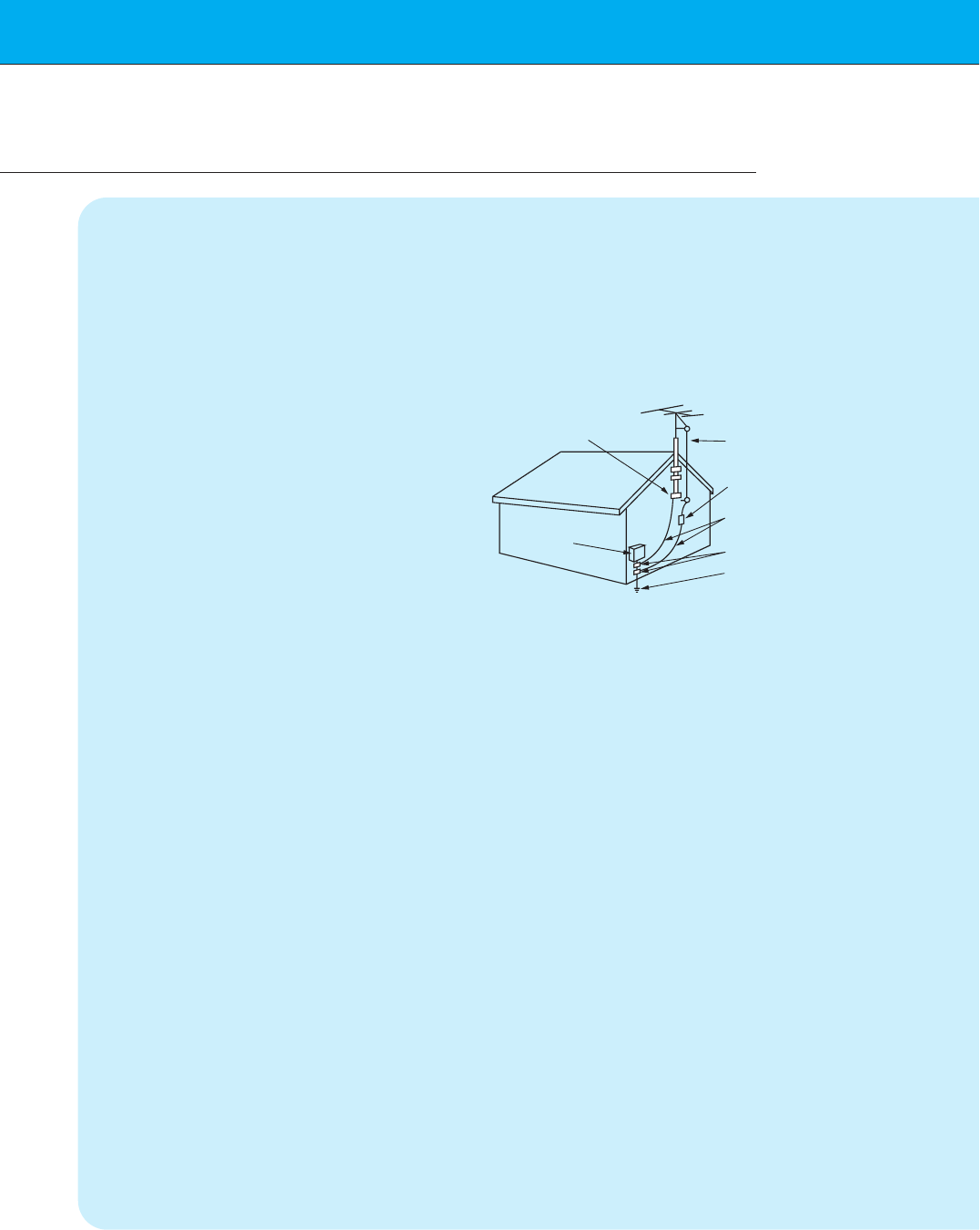
14. Outdoor Antenna Grounding
If an outside antenna or cable system is
connected to the product, be sure the
antenna or cable system is grounded so as
to provide some protection against voltage
surges and built-up static charges. Article
810 of the National Electrical Code (U.S.A.),
ANSI/ NFPA 70 provides information with
regard to proper grounding of the mast and
supporting structure, grounding of the lead-
in wire to an antenna discharge unit, size of
grounding conductors, location of antenna-
discharge unit, connection to grounding
electrodes, and requirements for the
grounding electrode.
15. Lightning
For added protection for this product
(receiver) during a lightning storm, or when
it is left unattended and unused for long
periods of time, unplug it from the wall outlet
and disconnect the antenna or cable sys-
tem. This will prevent damage to the product
due to lightning and power-line surges.
16. Power Lines
An outside antenna system should not be
located in the vicinity of overhead power
lines or other electric light or power circuits,
or where it can fall into such power lines or
circuits. When installing an outside antenna
system, extreme care should be taken to
keep from touching such power lines or cir-
cuits as contact with them might be fatal.
17. Overloading
Do not overload wall outlets and extension
cords as this can result in a risk of fire or
electric shock.
18. Object and Liquid Entry
Never push objects of any kind into this
(Continued from previous page)
Antenna Lead in Wire
Antenna Discharge Unit
(NEC Section 810-20)
Grounding Conductor
(NEC Section 810-21)
Ground Clamps
Power Service Grounding
Electrode System (NEC
Art 250, Part H)
Ground Clamp
Electric Service
Equipment
Example of Grounding According to National
Electrical Code Instructions
NEC - National Electrical Code

7
Safety instructions Monitor Overview Connections Basic operation Sleep timer Picture & Sound Special features Others
product through openings as they may
touch dangerous voltage points or short-out
parts that could result in a fire or electric
shock. Never spill liquid of any kind on the
product.
19. Servicing
Do not attempt to service this product your-
self as opening or removing covers may
expose you to dangerous voltage or other
hazards. Refer all servicing to qualified ser-
vice personnel.
20. Damage Requiring Service
Unplug this product from the wall outlet and
refer servicing to qualified service personnel
under the following conditions:
a. If the power-supply cord or plug is dam-
aged.
b. If liquid has been spilled, or objects have
fallen into the product.
c. If the product has been exposed to rain
or water.
d. If the product does not operate normally
by following the operating instructions.
Adjust only those controls that are cov-
ered by the operating instructions as an
improper adjustment of other controls
may result in damage and will often
require extensive work by a qualified
technician to restore the product to its
normal operation.
e. If the product has been dropped or the
cabinet has been damaged.
f. If the product exhibits a distinct change
in performance.
21. Replacement Parts
When replacement parts are required, be
sure the service technician has used
replacement parts specified by the manufac-
turer or have the same characteristics as
the original part. Unauthorized substitutions
may result in fire, electric shock, or other
hazards.
22. Safety Check
Upon completion of any service or repairs to
this product, ask the service technician to
perform safety checks to determine that the
product is in proper operating condition.
23. Wall or Ceiling Mounting
The product should be mounted to a wall or
ceiling only as recommended by the manu-
facturer. The product may slide or fall, caus-
ing serious injury to a child or adult, and
serious damage to the product.
24. Heat
The product should be situated away from
heat sources such as radiators, heat regis-
ters, stoves, or other products (including
amplifiers) that produce heat.
8
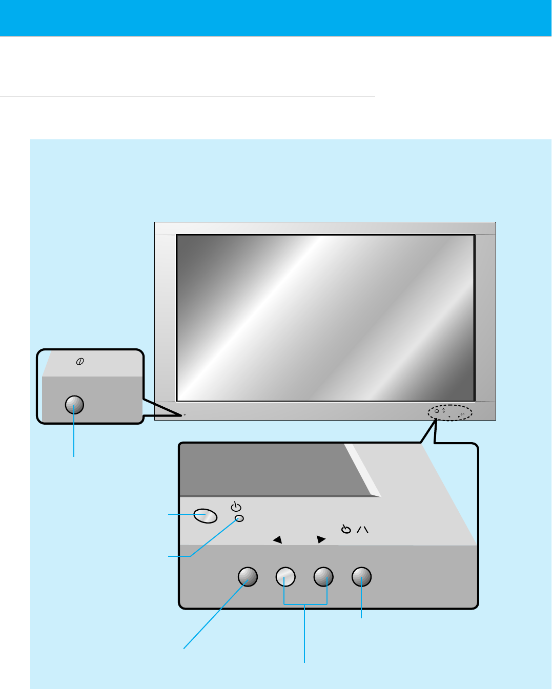
Front Panel Controls
ON/OFF
ON/OFF INPUT
SELECT
VOLUME
INPUT
SELECT VOLUME
Main power button
INPUT SELECT button
Power standby indicator
Illuminates red in standby
mode Illuminates green
when the Monitor is
turned on
Sub power button
VOLUME (FF,GG) buttons
Remote control sensor
<Front Panel Controls>
9
Safety instructions Monitor Overview Connections Basic operation Sleep timer Picture & Sound Special features Others
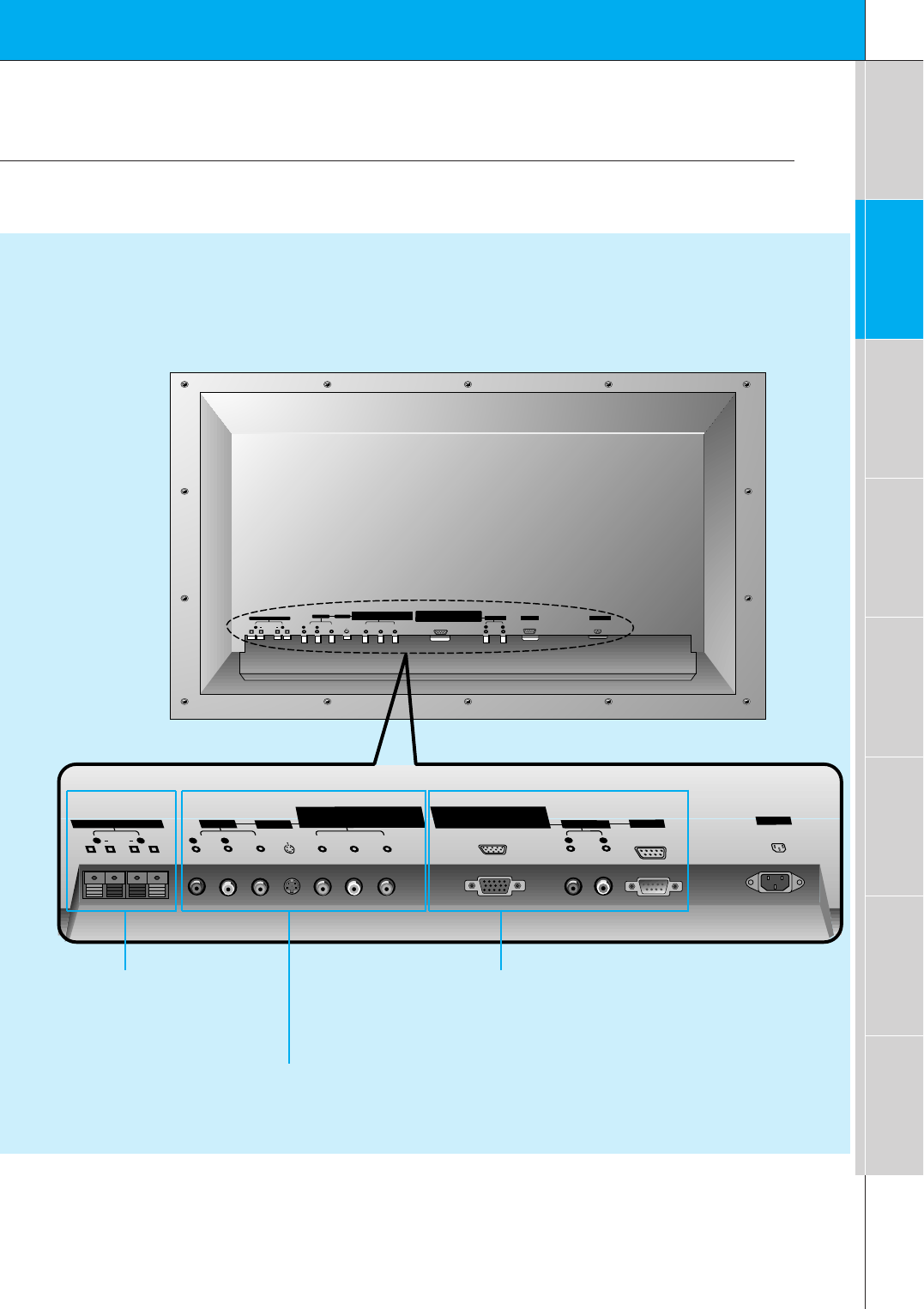
Connection Panel Overview
PY P
(+) ( ) (+)( )
AC INPUT
BR
Y
(+) ( ) (+)( )
P P
COMPONENT(480i/480p/720p/1080i)
(DVD/DTV INPUT)
RGB-DTV INPUT (480p/720p/1080i)
BR
RGB-PC INPUT (VGA/SVGA/XGA)
EXTERNAL SPEAKER (8Ω)
RL
AV INPUT S-VIDEO
AUDIO
(MONO)
R L VIDEO
COMPONENT (480i/480p/720p/1080i)
(DVD/DTV INPUT) RGB-PC INPUT(VGA/SVGA/XGA/SXGA)
RGB-DTV INPUT (480p/720p/1080i)
AUDIO
R L
AUDIO INPUT
EXTERNAL SPEAKER 8ΩAV INPUT S-VIDEO
R L R AUDIO VIDEO
(MONO)
L
AUDIO INPUT AC INPUT
R L
RS-232C
RS-232C
Back Panel
A/V INPUT /
S-VIDEO/
COMPONENT (480i/480p/720p/1080i)
DVD/DTV INPUT jacks
EXTERNAL SPEAKER
(8 ohm output) RGB-PC INPUT (VGA/SVGA/XGA)
RGB-DTV INPUT (480p/720p/1080i) /
AUDIO INPUT/
RS-232C jacks
10
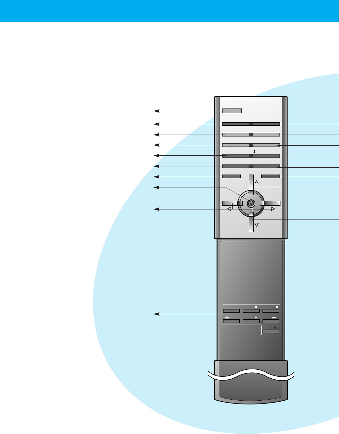
Remote Control Key Functions/Accessories
-When using the remote control aim it at the remote control sensor on the Monitor.
POWER
SLEEP INPUT SELECT
APC DASP
ARC STILL
PIP
PIP INPUT
MENU MUTE
OK
VOL
POWER STOP
PLAY FF
REC
REW
P/STILL
VOL
POSITION
/ TWIN PICTURE
POWER
SLEEP (Refer to p.33)
APC (Refer to p.34)
ARC (Refer to p.44)
PIP (Refer to p.26)
PIP INPUT (Refer to p.27)
MENU
OK
VCR BUTTONS
controls a LG video cassette
recorder.
VOLUME (FF, GG)
11
Safety instructions Monitor Overview Connections Basic operation Sleep timer Picture & Sound Special features Others
AS mark
LG TV
1.5V
1.5V
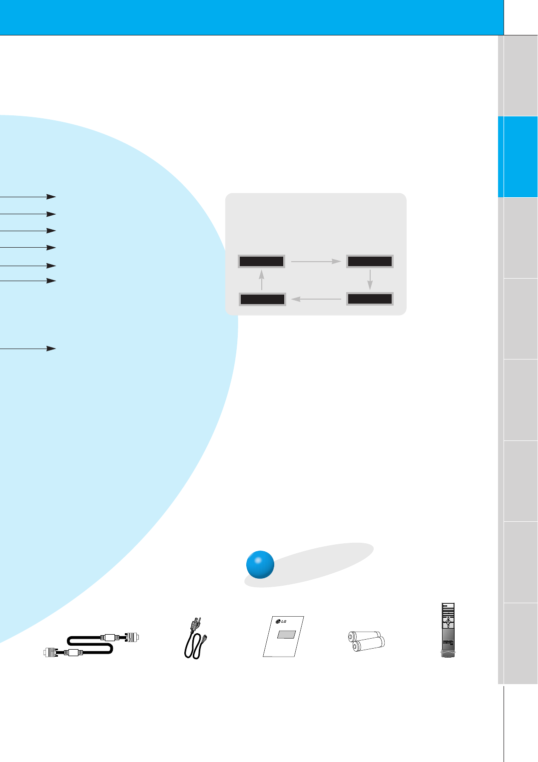
Accessories
D-sub 15 pin cable Power cord
POWER
SLEEP INPUT SELECT
APC DASP
ARC STILL
PIP
PIP INPUT
MENU MUTE
OK
VOL
POWER STOP
PLAY FF
REC
REW
P/STILL
VOL
POSITION
/ TWIN PICTURE
Remote control
Owner’s Manual Alkaline batteries
INPUT SELECT button on the remote
control
Each press of this button changes the mode as
shown below.
S-VIDEO
COMPONENT
VIDEO
RGB
INPUT SELECT
DASP (Refer to p.38)
STILL (Refer to p.40)
POSITION (Refer to p.27)
DD/ EE
selects a menu item.
MUTE
switches the sound on or off.
No function
12
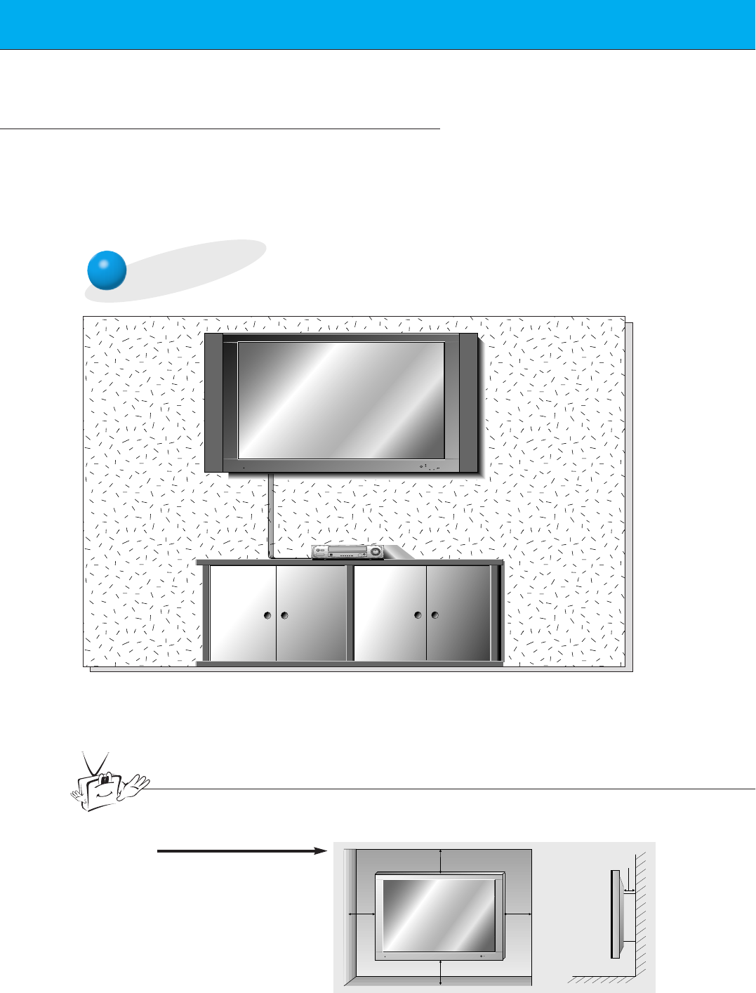
Monitor Installation
- It is recommended that this product only be used at an altitude of less than 3281 feet
(1000m) to get the best quality picture and sound.
- This plasma display is designed to be mounted horizontally (wide viewing).
- Your MU-42PZ11/15 series models (Monitor) can be installed on a wall as shown below,
or on a desktop pedestal as shown on the next page. Wall mount and stands are
optional, and are not supplied with the monitor.
Wall Mount Installation
• The monitor can be installed on the wall as shown above.
(For further information, refer to the optional ‘(Tilt) wall mounting bracket
Installation and Setup Guide’.)
• Speakers are optional, and shown for illustration only.
Tips
•Install this monitor only in a location where adequate ventilation is available.
4inch
4inch
4inch4inch
1.18inch
a. ( Wall mount minimum
allowable clearances
for adequate ventilation )
13
Safety instructions Monitor Overview Connections Basic operation Sleep timer Picture & Sound Special features Others
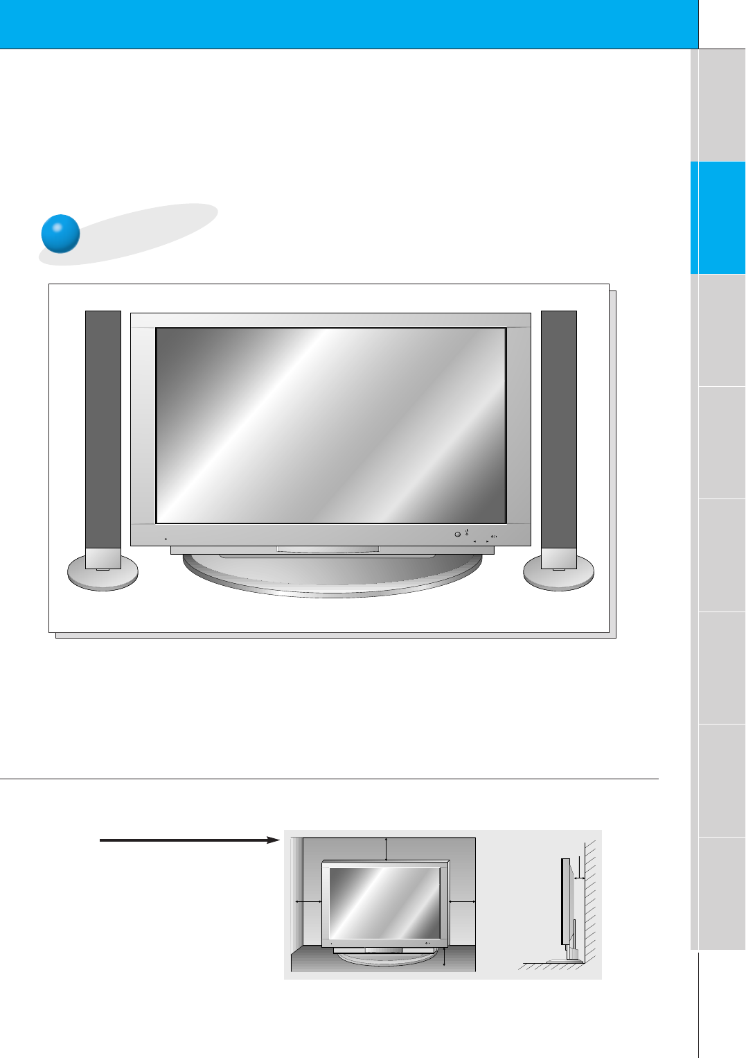
Desktop Pedestal Installation
• The Monitor can be installed on a desk as shown above.
(For further information, refer to the optional ‘Desktop Stand Installation and Setup Guide’.)
• Speakers shown are optional, and shown for illustration only.
4inch
4inch
2.36inch
4inch
1.18inch
b. ( Pedestal mount minimum
allowable clearances for
adequate ventilation )
14
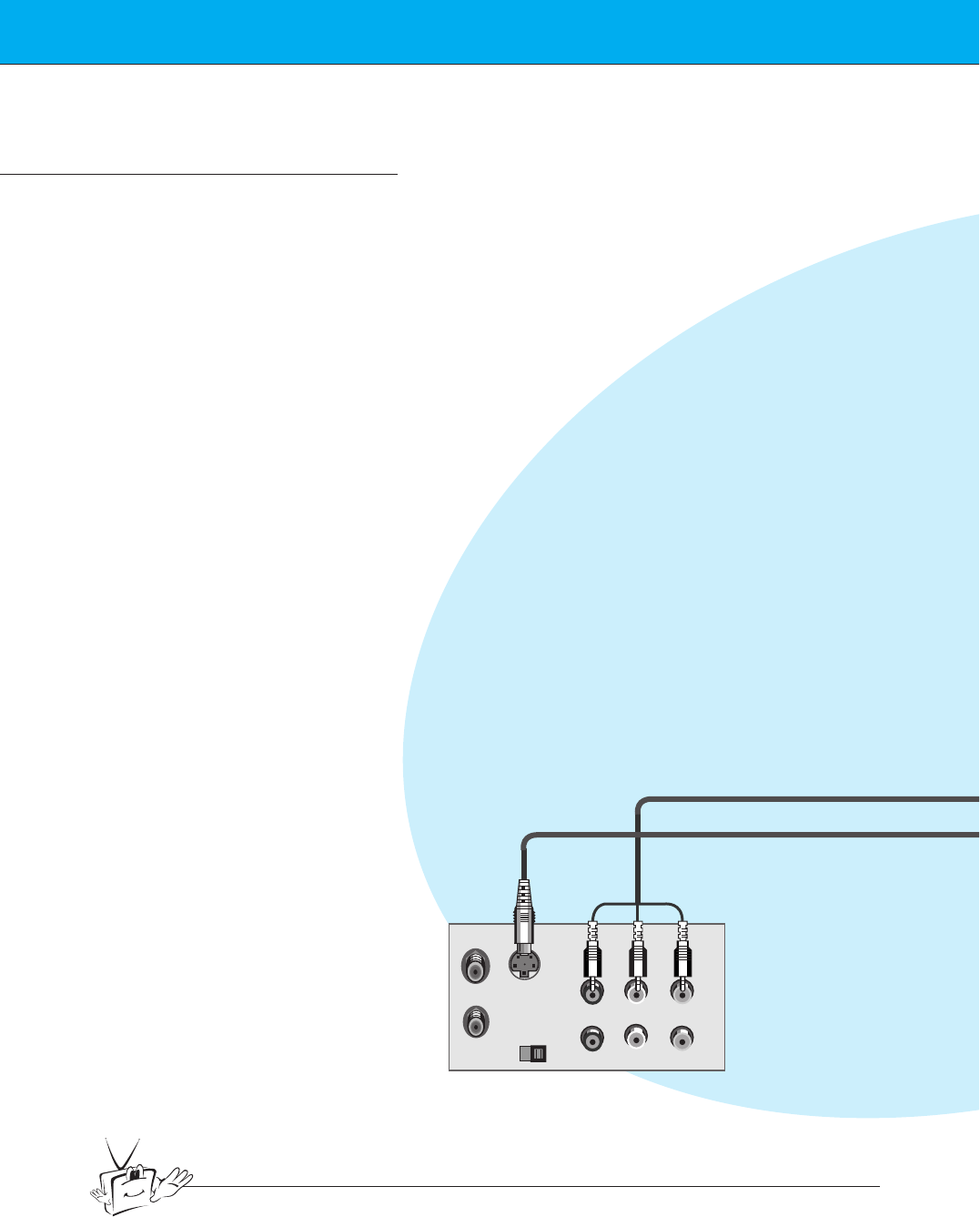
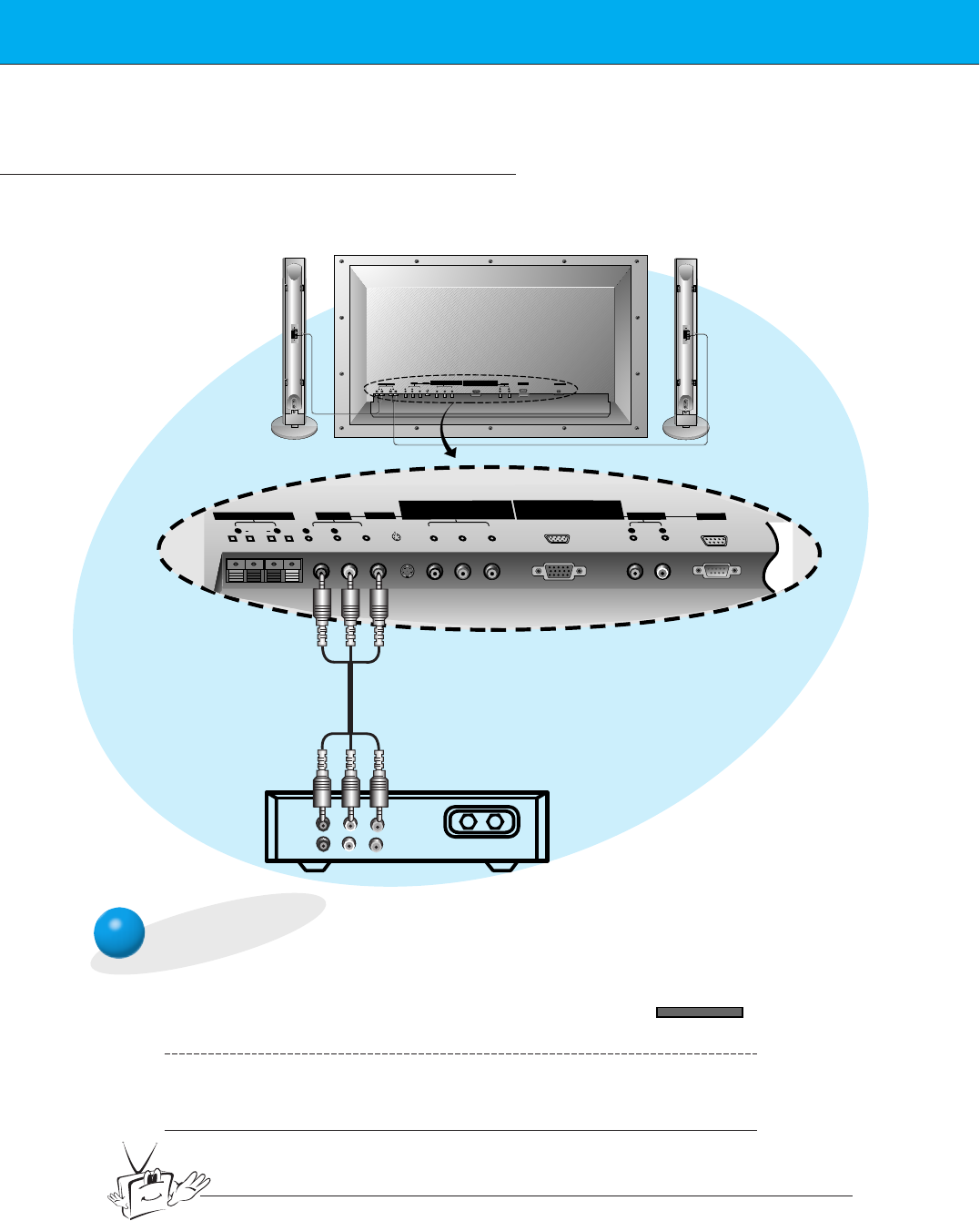
VCR Setup
Tips
• To avoid picture noise (interference), leave an adequate distance (20 inches or more)
between the VCR and monitor.
S-VIDEO OUT
IN
(R) AUDIO (L) VIDEO
< Back panel of VCR >
- As shown below, when connecting the Monitor to a VCR, match the colors of AV input
jacks on the Monitor with the output jacks on the VCR: Video = yellow, Audio (Left) =
white, Audio (Right) = red.
- If you have a mono VCR, connect the audio cable from the VCR to the AUDIO(L/MONO)
input of the Plasma Monitor.
- If you connect an S-VIDEO VCR to the S-VIDEO input, the picture quality is improved,
compared to connecting a regular VCR to the Video input.
- Avoid having a fixed image remain on the screen for a long period of time. A frozen still
picture from a VCR (or if a CH label is displayed) displayed on the screen for prolonged
periods will result in an image ghost remaining even when you change the image. Avoid
prolonged display of a still image.
15
Safety instructions Monitor Overview Connections Basic operation Sleep timer Picture & Sound Special features Others
PY P
(+) ( ) (+)( )
AC INPUT
BR
Y
(+) ( ) (+)( )
P P
COMPONENT(480i/480p/720p/1080i)
(DVD/DTV INPUT)
RGB-DTV INPUT (480p/720p/1080i)
BR
RGB-PC INPUT (VGA/SVGA/XGA)
EXTERNAL SPEAKER (8Ω)
RL
AV INPUT S-VIDEO
AUDIO
(MONO)
R L VIDEO
COMPONENT (480i/480p/720p/1080i)
(DVD/DTV INPUT) RGB-PC INPUT(VGA/SVGA/XGA/SXGA)
RGB-DTV INPUT(480p/720p/1080i)
AUDIO
R L
AUDIO INPUT
EXTERNAL SPEAKER 8ΩAV INPUT S-VIDEO
R L R AUDIO VIDEO
(MONO)
L
AUDIO INPUT AC INPUT
RS-232C
R L
RS-232C
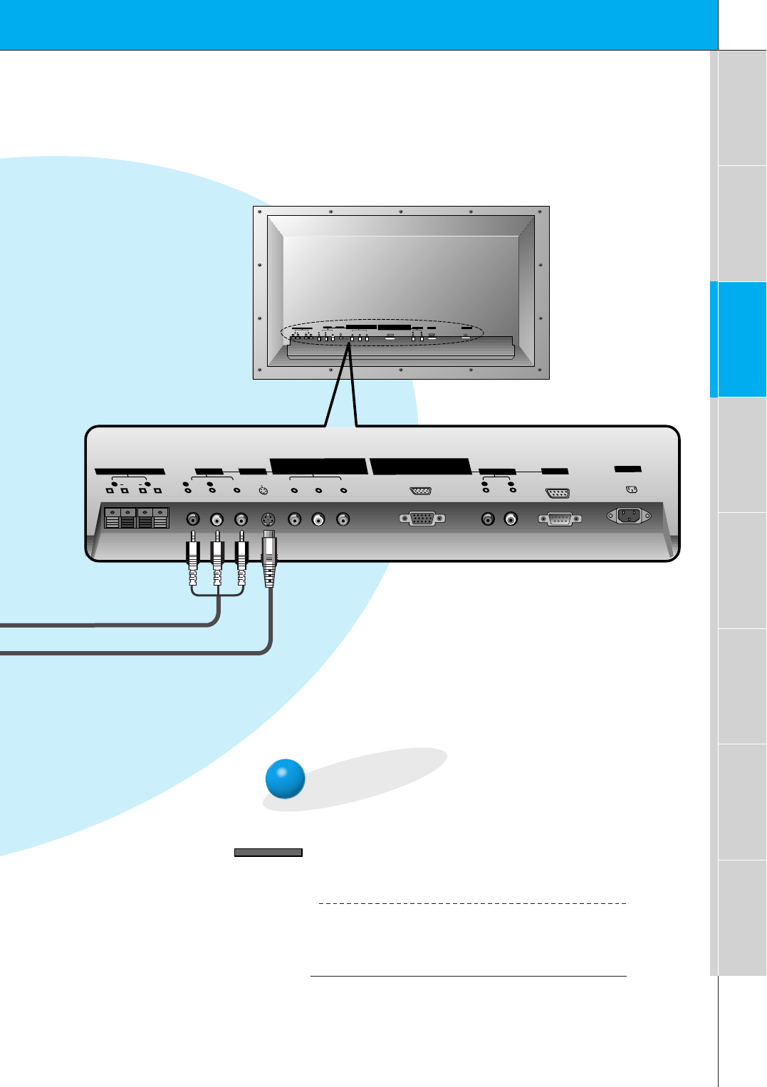
< Back panel of the Monitor >
To watch VCR
Press INPUT SELECT button on the
remote control and select VIDEO.
(When connecting with S-Video, select the
S-VIDEO.)
1
Insert a video tape into the VCR and press
the PLAY button on the VCR. See VCR
owner’s manual.
2
INPUT SELECT
16
Cable TV Setup
- After subscribing to a cable TV service from a local provider and installing a converter,
you can watch cable TV programming. This monitor cannot display TV programming
without a TV tuner or cable TV converter box.
TV
VCR RF Cable
(R) AUDIO (L) VIDEO
Y
(+) ( ) (+)( )
EXTERNAL SPEAKER(8Ω)
R L R
AUDIO VIDEO
(MONO)
L
P P
COMPONENT(480i/480p/720p/1080i)
(DVD/DTV INPUT)
BR
RGB-DTV INPUT
RGB-PC INPUT (VGA/SVGA/XGA)
(480p/720p/1080i)
PY P
(+) ( ) (+)( )
AC INPUT
BR
EXTERNAL SPEAKER (8Ω)
RL
AV INPUT S-VIDEO
AUDIO
(MONO)
R L VIDEO
COMPONENT (480i/480p/720p/1080i)
(DVD/DTV INPUT) RGB-PC INPUT(VGA/SVGA/XGA/SXGA)
RGB-DTV INPUT(480p/720p/1080i)
AUDIO
R L
AUDIO INPUT
AV INPUT
R L
AUDIO INPUT
RS-232C
RS-232C
S-VIDEO
To watch cable TV
Press INPUT SELECT button on the
remote control and select VIDEO source.
1
Tune to cable service provided channels
using the cable box.
2
Tips
•For further information regarding cable TV service, contact your local
cable TV service provider(s).
< Monitor back panel >
< Cable box >
Speakers shown
for illustration
only.
INPUT SELECT
17
Safety instructions Monitor Overview Connections Basic operation Sleep timer Picture & Sound Special features Others
Y
(+) ( ) (+)( )
EXTERNAL SPEAKER(8Ω)
R L R
AUDIO VIDEO
(MONO)
L
P P
COMPONENT(480i/480p/720p/1080i)
(DVD/DTV INPUT)
BR
RGB-DTV INPUT
RGB-PC INPUT (VGA/SVGA/XGA)
(480p/720p/1080i)
PY P
(+) ( ) (+)( )
AC INPUT
BR
EXTERNAL SPEAKER (8Ω)
RL
AV INPUT S-VIDEO
AUDIO
(MONO)
R L VIDEO
COMPONENT (480i/480p/720p/1080i)
(DVD/DTV INPUT) RGB-PC INPUT(VGA/SVGA/XGA/SXGA)
RGB-DTV INPUT(480p/720p/1080i)
AUDIO
R L
AUDIO INPUT
AV INPUT S-VIDEO
R L
R L
AUDIO VIDEO
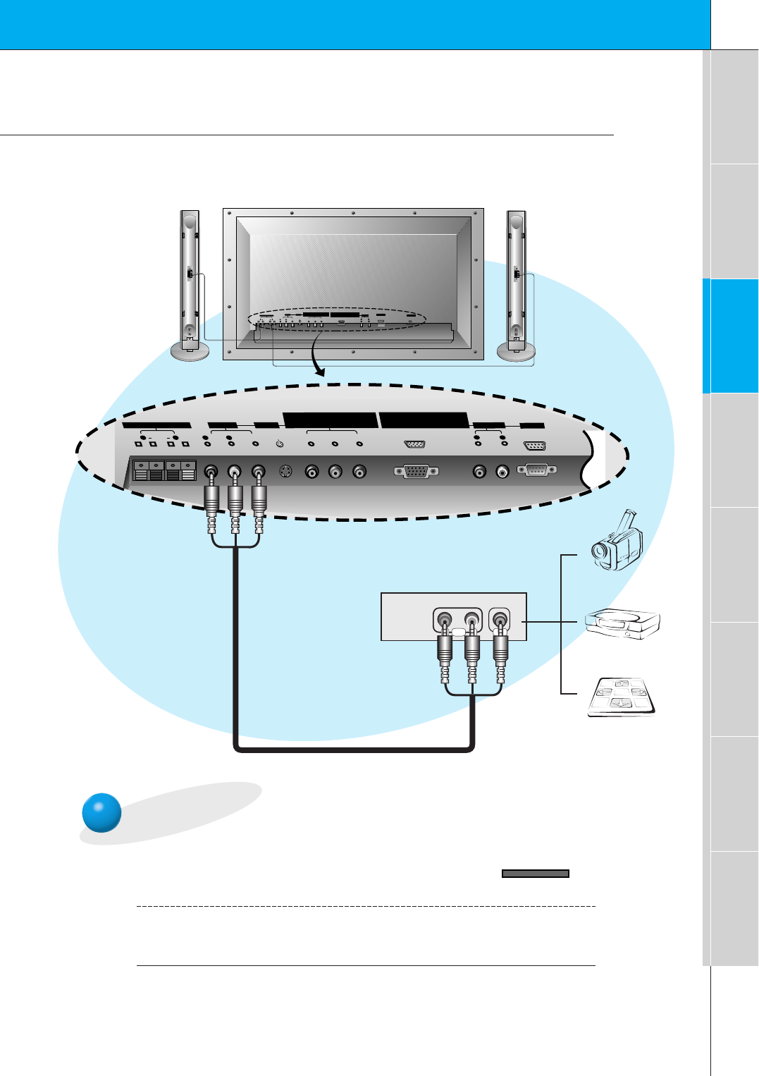
Video game set
DDR
Camcorder
RS-232C
AUDIO INPUT
RS-232C
To watch external AV source
Press INPUT SELECT button on the
remote control of the monitor to select
VIDEO.
1
Operate the corresponding external equip-
ment. See external equipment operating
guide.
2
External AV Source Setup
- As shown below, when connecting the Monitor to an external source, match the colors of AV
input jacks on the Monitor with the output jacks on the audio/video equipment: Video = yel-
low, Audio (Left) = white, Audio (Right) = red.
<Back panel of the Monitor>
INPUT SELECT
18
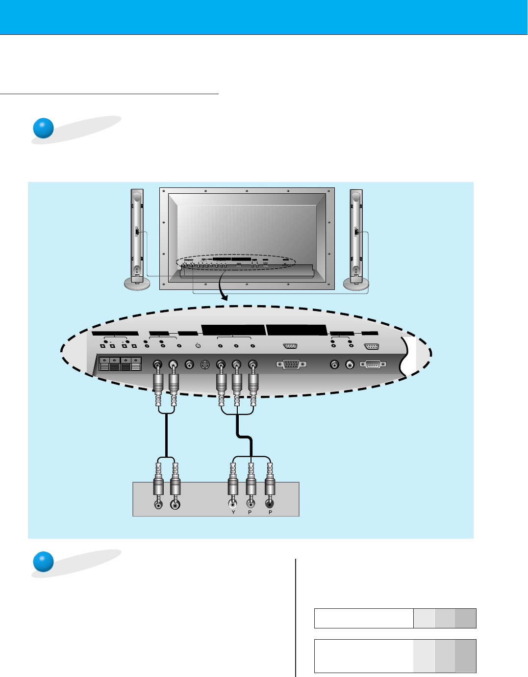
DVD Setup
• Connect DVD video inputs to Y, PB, PRof COMPONENT (480i/480p/720p/1080i)
(DVD/DTV INPUT) and audio inputs to Audio jacks of AV INPUT.
How to connect a DVD (digital video disk player)
How to use
• Turn on the DVD player, and insert a DVD.
• Press INPUT SELECT button on the remote control of the
monitor to select COMPONENT. Use the DVD player
according to its owner’s manual.
•Component Input ports
Connect DVD player jacks to Monitor
Component input jacks as indicated below.
BR
(R) AUDIO (L)
Y
(+) ( ) (+)( )
EXTERNAL SPEAKER(8Ω)
R L R
AUDIO VIDEO
(MONO)
L
P P
COMPONENT(480i/480p/720p/1080i)
(DVD/DTV INPUT)
BR
RGB-DTV INPUT
RGB-PC INPUT (VGA/SVGA/XGA)
(480p/720p/1080i)
PY P
(+) ( ) (+)( )
AC INPUT
BR
EXTERNAL SPEAKER (8Ω)
RL
AV INPUT S-VIDEO
AUDIO
(MONO)
R L VIDEO
COMPONENT (480i/480p/720p/1080i)
(DVD/DTV INPUT) RGB-PC INPUT(VGA/SVGA/XGA/SXGA)
RGB-DTV INPUT(480p/720p/1080i)
AUDIO
R L
AUDIO INPUT
AV INPUT S-VIDEO
R L
AUDIO INPUT
RS-232C
RS-232C
< Back panel of a DVD player>
Component input jacks
on the Monitor YPBPR
Video output jacks
of DVD player
Y
Y
Y
Y
Pb
B-Y
Cb
PB
Pr
R-Y
Cr
PR
<Back panel of the Monitor>