LG Electronics USA MU42PZ41V Plasma Monitor User Manual FA91196 LG1214
LG Electronics USA Plasma Monitor FA91196 LG1214
UserManual.wiki
>
LG Electronics USA
>
MU42PZ41V User Manual
user manual
Navigation menu
Upload a User Manual
Namespaces
Wiki Guide
HTML
PDF
Info
Views
User Manual
Discussion / Help
Navigation
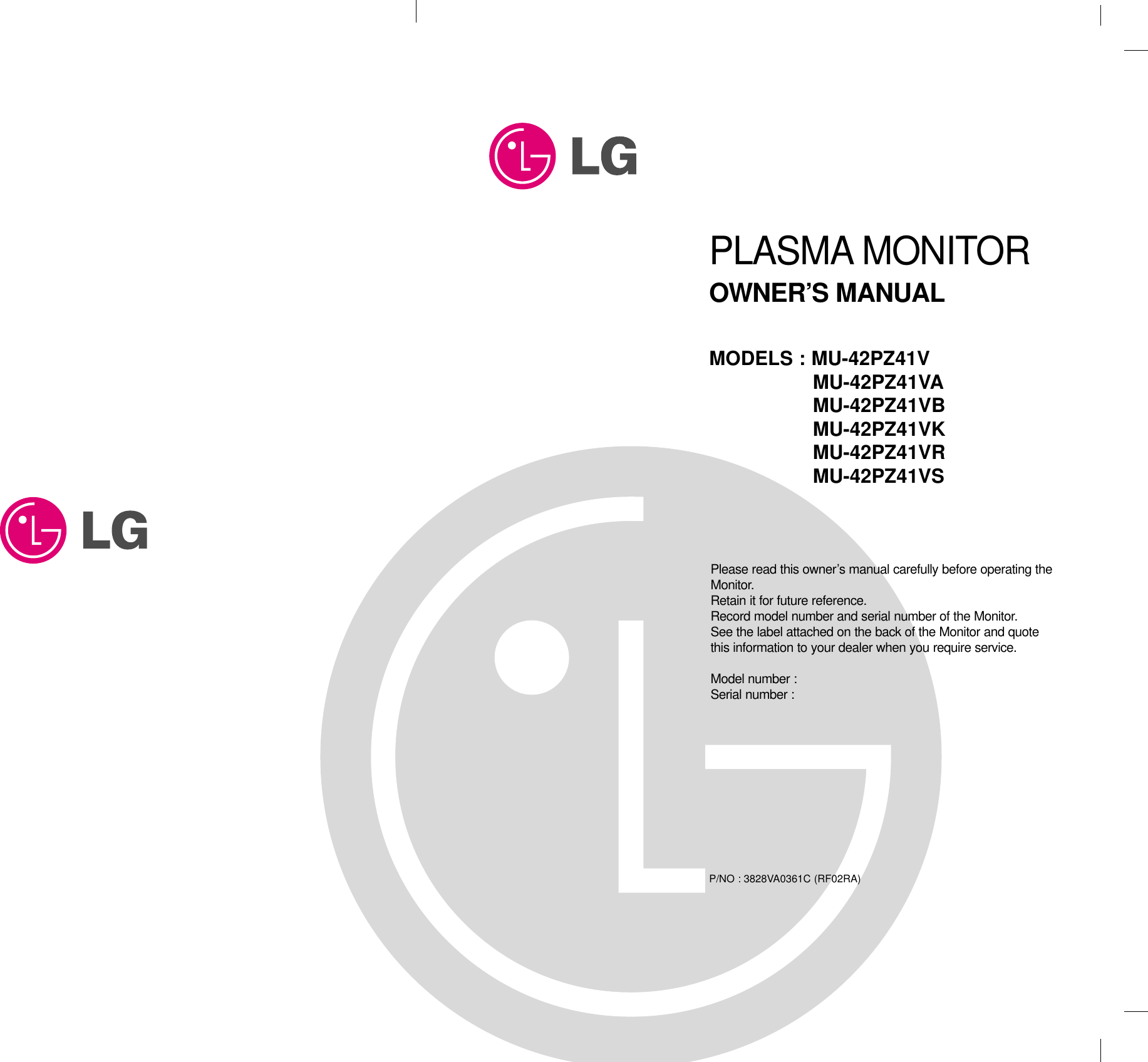
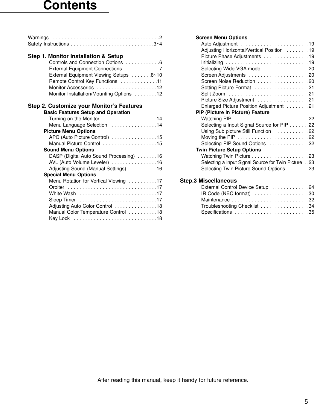
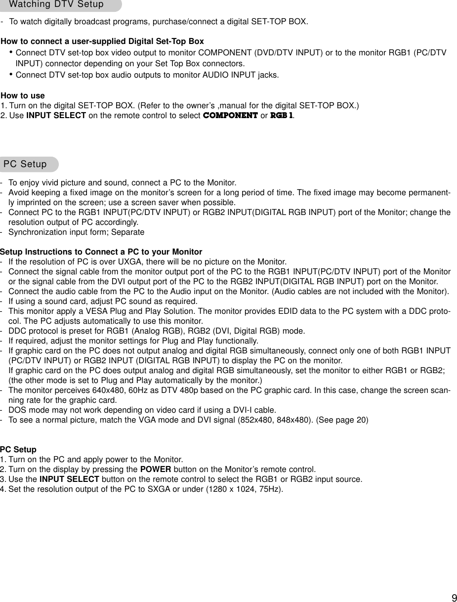
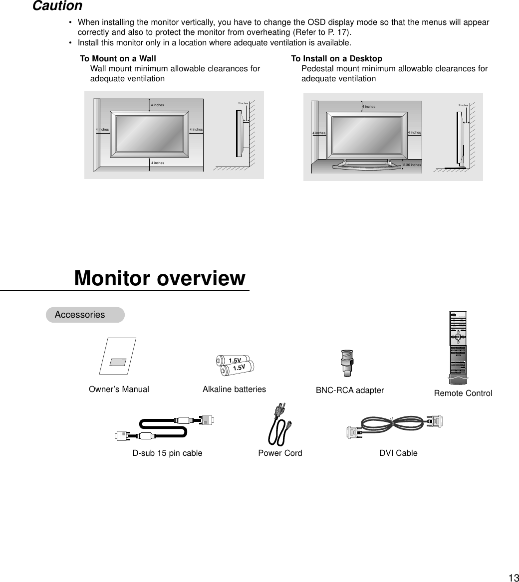
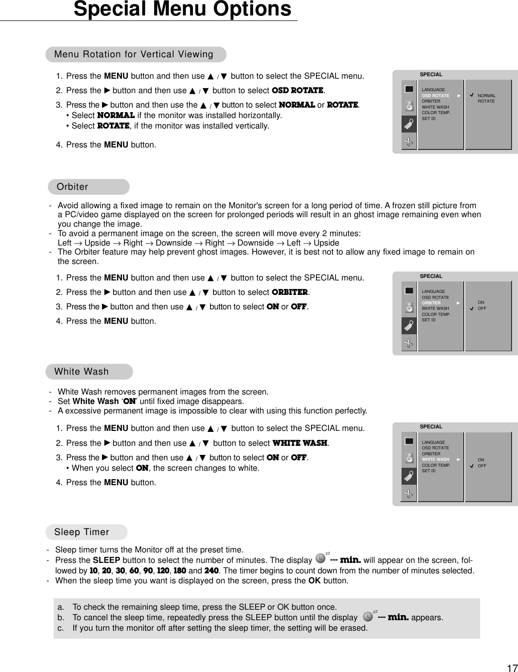
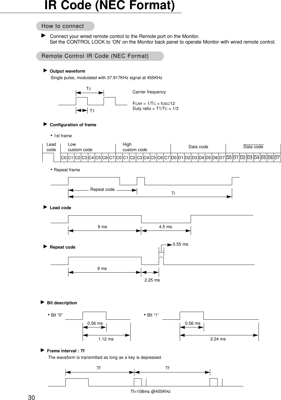
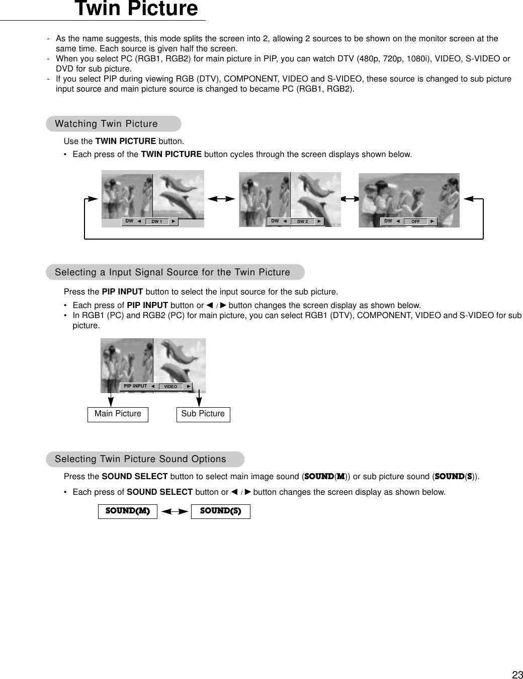
![20Screen Menu OptionsSelecting WSelecting Wide VGAide VGA mode (RGB1, RGB2 [PC] mode only)mode (RGB1, RGB2 [PC] mode only)- To see a normal picture, match the resolution of RGB mode and selection of VGA mode. - When selecting 852x480 or 848x480, the screen is changed to 16:9 aspect ratio automatically. At this time, Twin picture doesn’t work.1. Press the MENU button and then use D /Ebutton to select the SCREEN menu.2. Press the Gbutton and then use D /Ebutton to select VGA MODE.3. Press the Gbutton and then use D /Ebutton to select the desired VGA resolution.4. Press the MENU button.SCREEN ADJ. VGA MODE GARC PIP/DWZOOM IN/OUTSCREEN640x480848x480852x480Screen Screen Adjustments (VIDEO and S-VIDEO mode only)Adjustments (VIDEO and S-VIDEO mode only)- Use this function to correct jittering or picture instability while viewing a video tape.- To reduce the picture noise which may appear on the screen during watching the TV in a weak signal area.1. Press the MENU button and then use D /Ebutton to select the SCREEN menu.2. Press the Gbutton and then use D /Ebutton to select SCREEN ADJ..3. Press the Gbutton and then use D /Ebutton to select TV or VCR.• Select the VCR option if watching a VCR. • Select the TV option for other equipment.(Except VCR)4. Press the MENU button.SCREEN ADJ. GYNRARC PIP/DWZOOM IN/OUTSCREENTVVCR✓SCREEN ADJ. GYNRARC PIP/DWZOOM IN/OUTSCREENTVVCRSCREEN ADJ. GYNRARC PIP/DWZOOM IN/OUTSCREENTVVCR✓SCREEN ADJ. YNR GARC PIP/DWZOOM IN/OUTSCREENONOFFScreen Noise Reduction: Luminance Noise Reduction (VIDEO, S-VIDEO and COMPONENTScreen Noise Reduction: Luminance Noise Reduction (VIDEO, S-VIDEO and COMPONENT 480i mode only)480i mode only)1. Press the MENU button and then use D / Ebutton to select the SCREEN menu.2. Press the Gbutton and then use D / Ebutton to select YNR.3. Press the Gbutton and then use D / Ebutton to select ON or OFF.4. Press the MENU button.](https://usermanual.wiki/LG-Electronics-USA/MU42PZ41V/User-Guide-290708-Page-20.png)
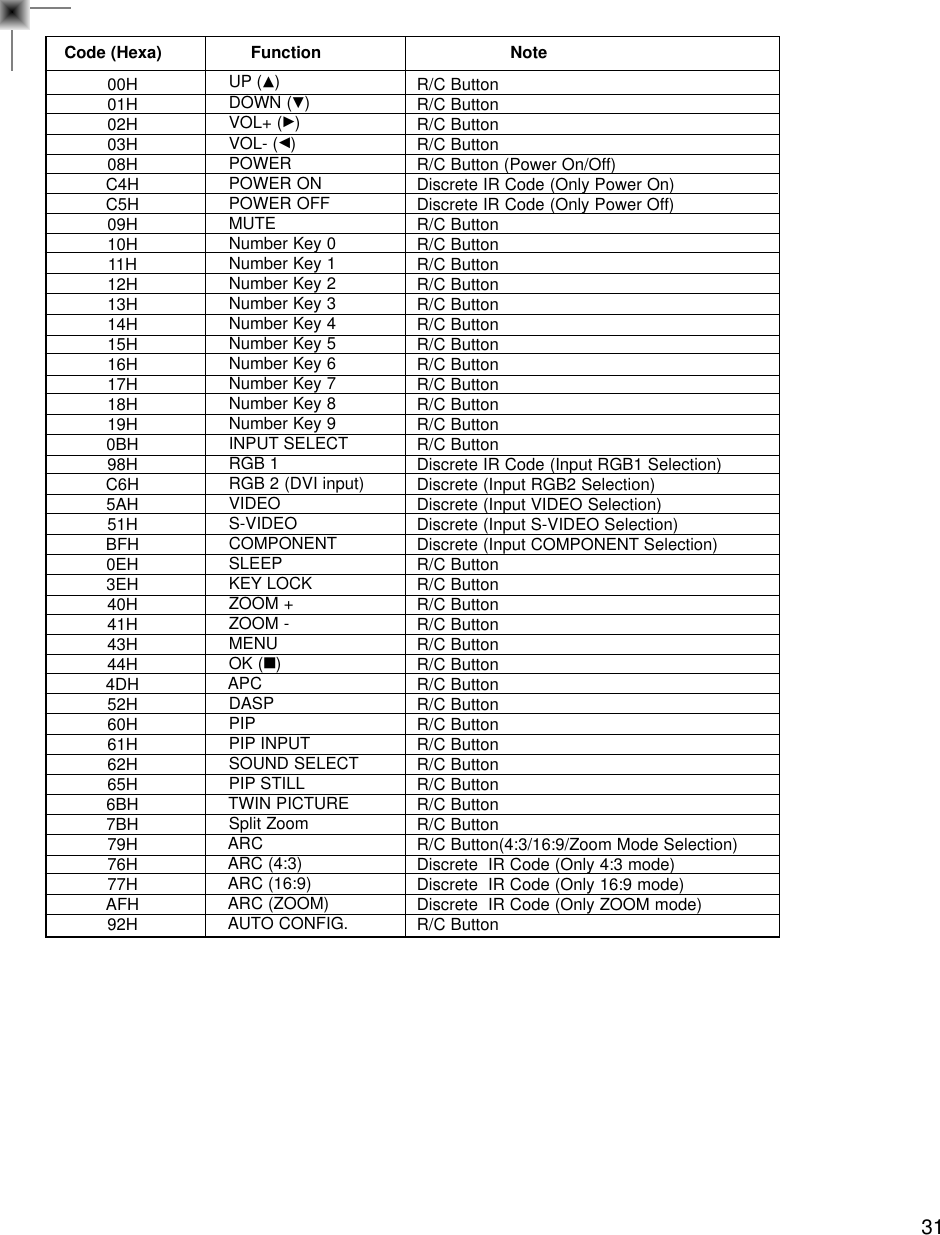
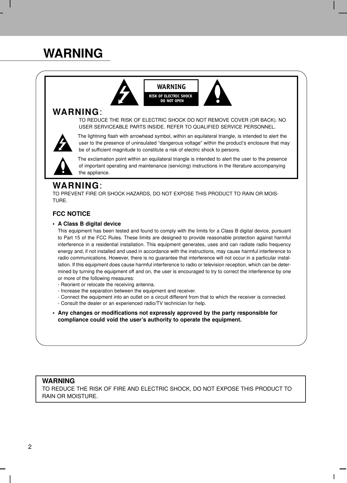
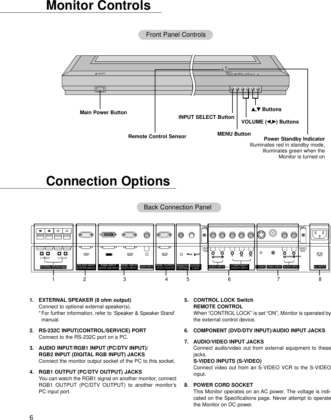
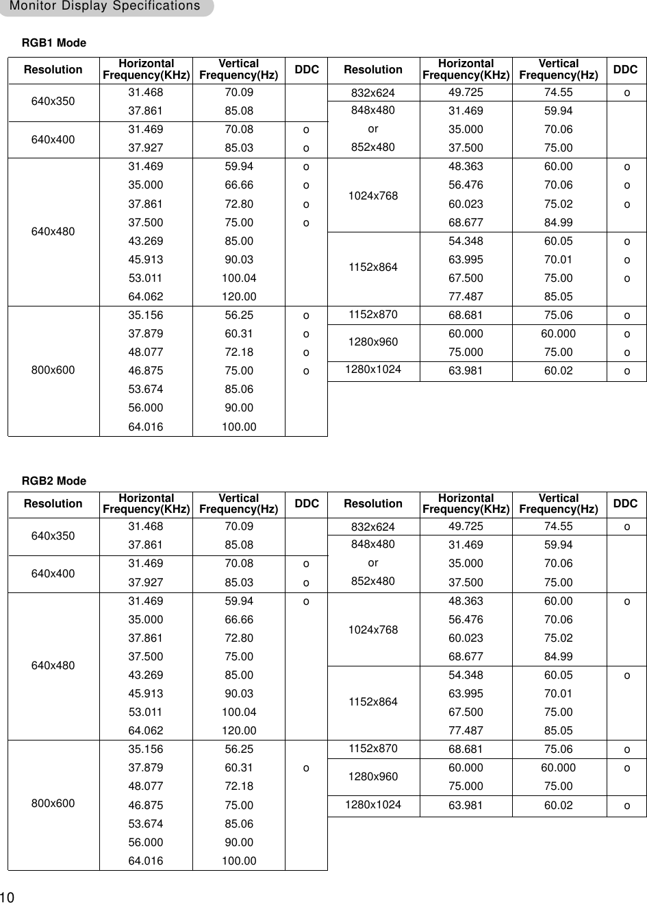
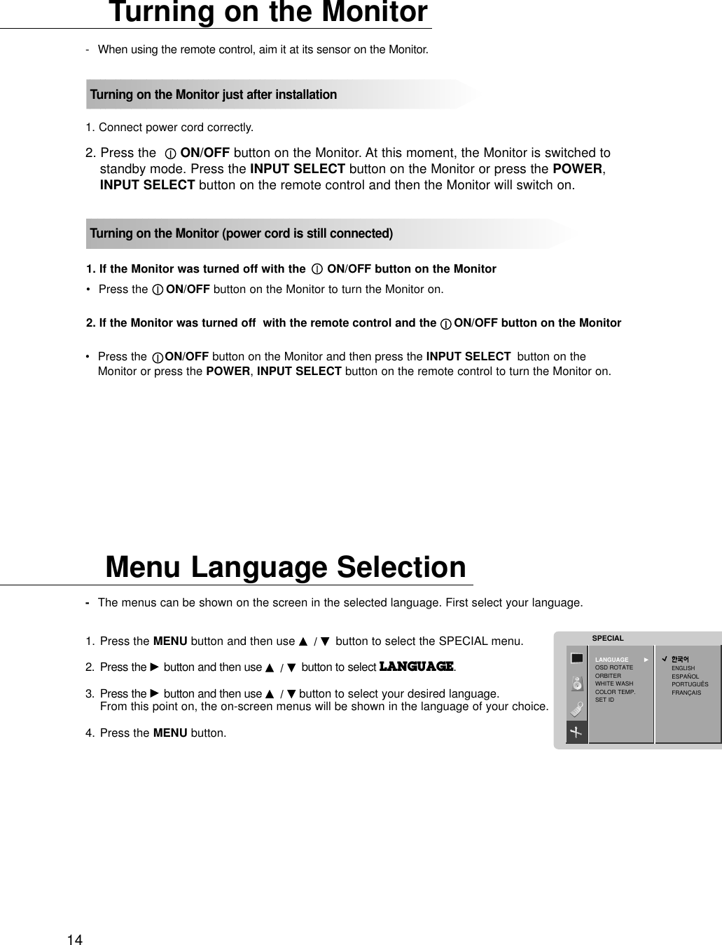
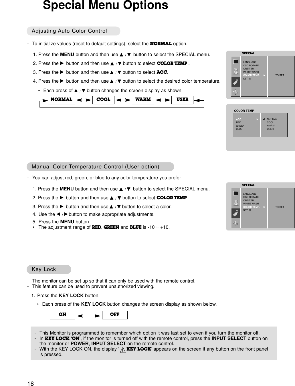
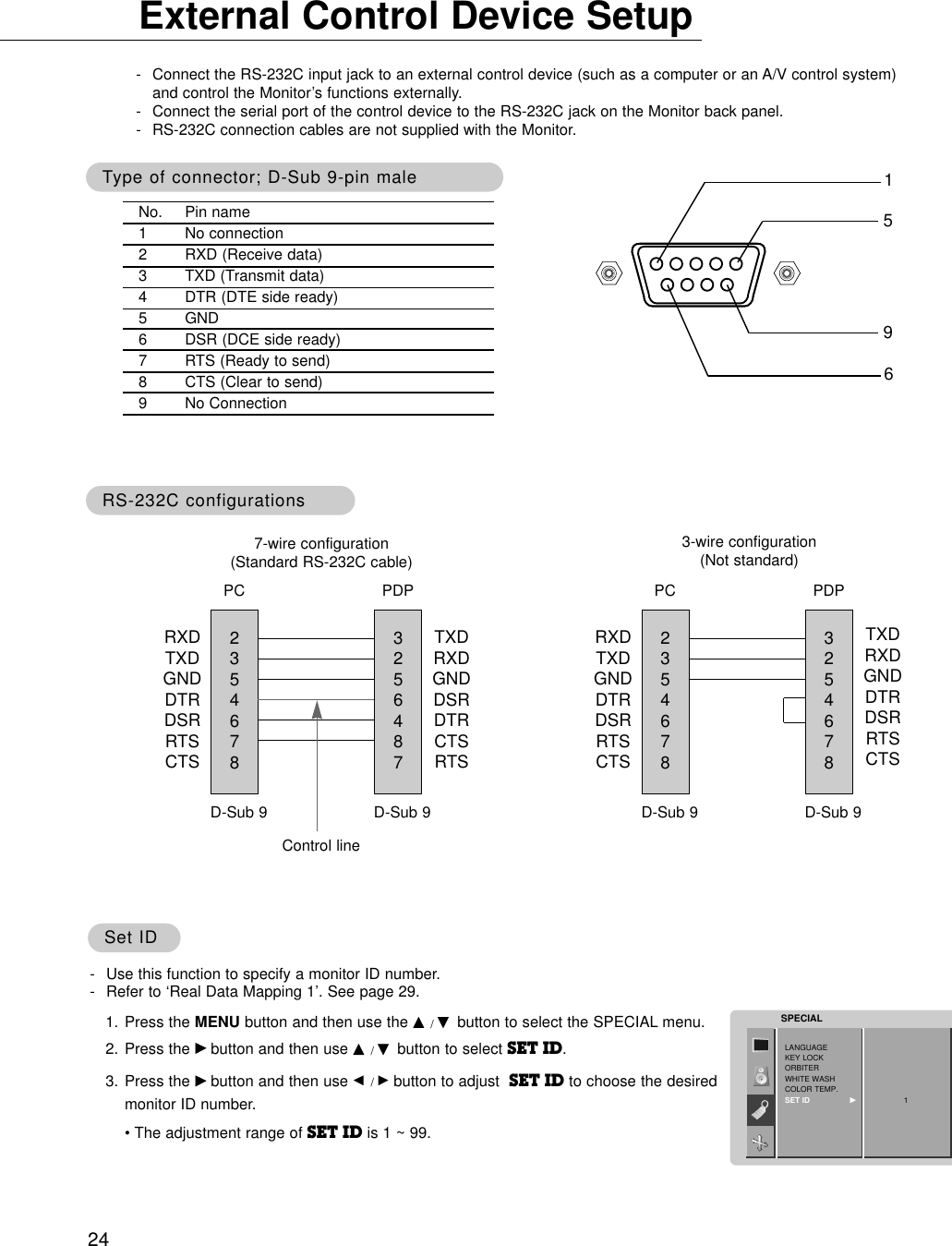
![21Press the ZOOM+/ZOOM- button to enlarge or reducethe picture size.•The adjustment range of Zoom is 0~20.Enlarged Picture Position Enlarged Picture Position AdjustmentAdjustmentAdjust the main picture position with the D / E/ F / G buttons in enlarged picture mode.◀▶▲▼100 %ZOOM : 0DFGE◀▶▲▼100 %ZOOM : 0DFGESetting Picture FormatSetting Picture Format- You are available to 4:3 and 16:9 in RGB and RGB2 (PC).- You are available to 16:9, 4:3 and ZOOM in VIDEO, S-VIDEO, RGB-DTV, and COMPONENT.- If 4:3 is on the screen for a long time, that fixed image may remain visible.1. Press the ARC button to select a desired picture format.•Each press of ARC button or F / Gbutton changes the screen display as shown below.•You can also select 16:9, 4:3 or ZOOM in the SCREEN menu.ARC F G16 : 9 ARC F G4 : 3 ARC F GZOOMSplit ZoomSplit Zoom- This is the function to enlarge the screen with regular ration.-It’s available to use this function in every input source.1. Press the SPLIT ZOOM button.•Each press of SPLIT ZOOM button changes the screen display as shown below.•Press the number button to select the section you enlarge. If you choose No.5, the 5 section is enlarged.In case of choosing the No.5 The 5 section is changed toa full screen.125412 345678912 3456789Picture Size Picture Size Adjustment (RGB1 [DTV], Adjustment (RGB1 [DTV], COMPONENTCOMPONENT, VIDEO, S-VIDEO mode only), VIDEO, S-VIDEO mode only)](https://usermanual.wiki/LG-Electronics-USA/MU42PZ41V/User-Guide-290708-Page-21.png)
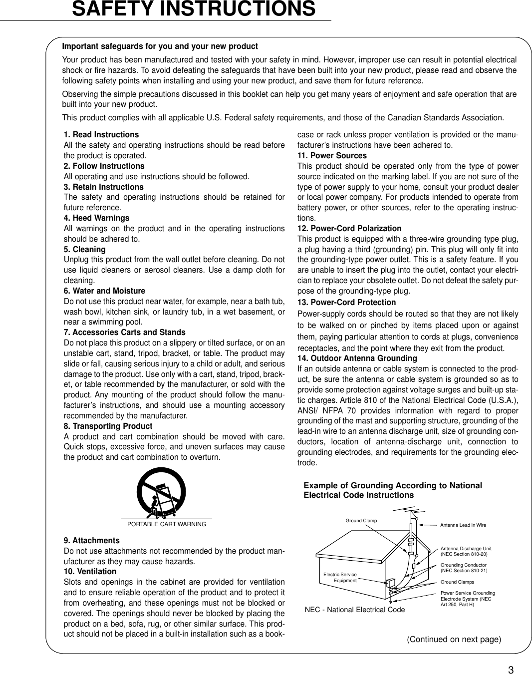
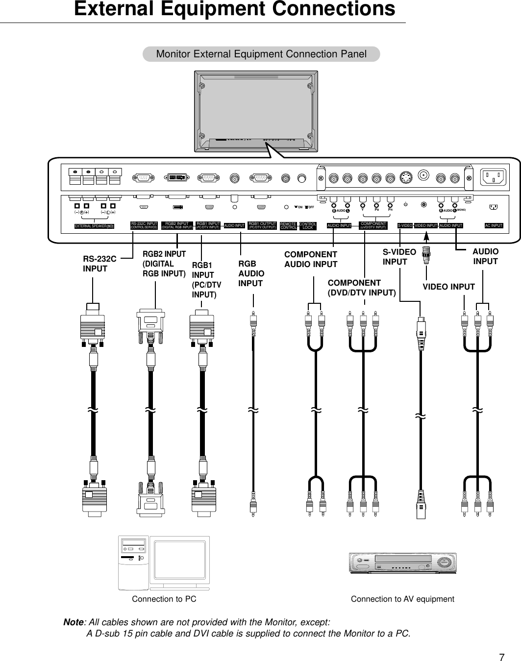
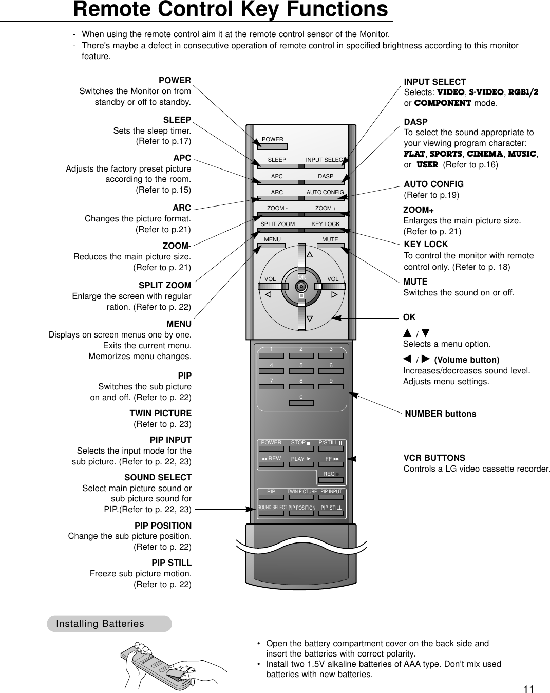
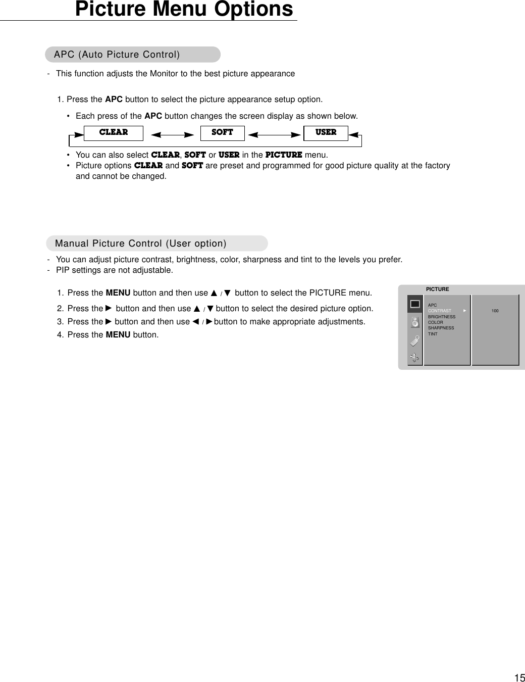
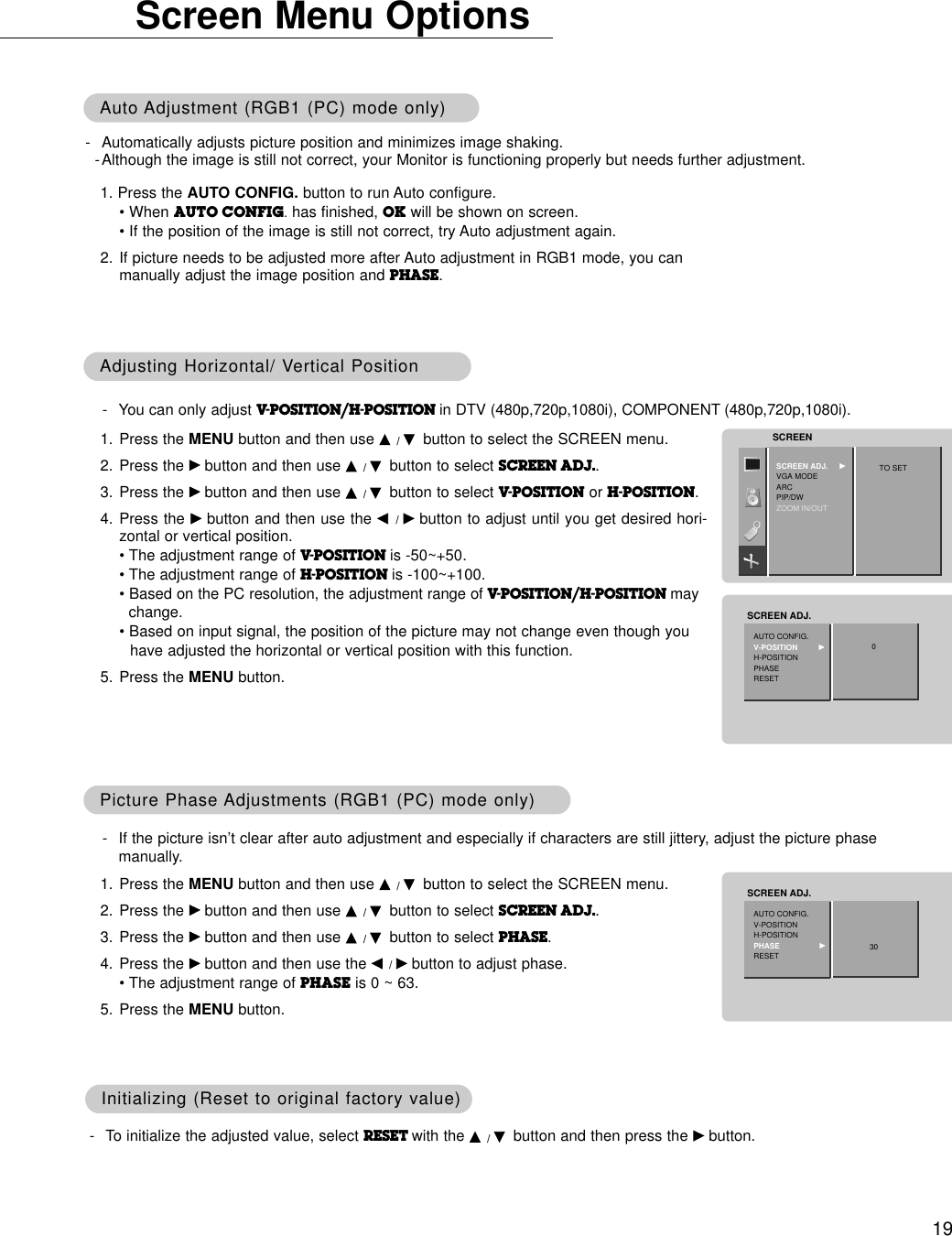
![25Transmission* [Command 1] : First command to control PDP set.(j or k)* [Command 2] : Second command to control PDP set.* [Set ID] : You can adjust the set ID to choose desired monitor ID number in special menu. See previous page. Adjustment range is 1 ~ 99. When selecting Set ID ‘0’, every connected PDP set is controlled.Set ID is indicated as decimal (1~99) onmenu and as Hexa decimal (0x0~0x63)on trasmission/receiving protocol.* [DATA] : To transmit command data.Transmit ‘FF’data to read status of command.* [Cr] : Carriage ReturnASCII code ‘0x0D’* [ ] : ASCII code ‘space (0x20)’[Command1][Command2][ ][Set ID][ ][Data][Cr]OK Acknowledgement01. Power k a 0 ~ 102. Input Select k b 0 ~ 403. Aspect Ratio k c 0 ~ 204. Screen Mute k d 0 ~ 105. Volume Mute k e 0 ~ 106. Volume Control k f 0 ~ 6407. Contrast k g 0 ~ 6408. Brightness k h 0 ~ 6409. Color k i 0 ~ 6410. Tint k j 0 ~ 6411. Sharpness k k 0 ~ 6412. OSD select k l 0 ~ 113. Remote control lock mode k m 0 ~ 114. PIP/Twin picture (DW) k n 0 ~ 415. PIP sound select k p 0 ~ 116. PIP position k q 0 ~ 317. Treble k r 0 ~ 6418. Bass k s 0 ~ 6419. Balance k t 0 ~ 6420. Color temperature (ACC) k u 0 ~ 321. Red adjustment k v 0 ~ 6422. Green adjustment k w 0 ~ 6423. Blue adjustment k $ 0 ~ 6424. PIP input source k y 0 ~ 325. Orbiter j p 0 ~ 126. White Wash j q 0 ~ 1COMMAND 1 COMMAND 2 DATA(Hexadecimal)* The Monitor transmits ACK (acknowledgement) based onthis format when receiving normal data. At this time, if thedata is data read mode, it indicates present status data. Ifthe data is data write mode, it returns the data of the PCcomputer.[Command2][ ][Set ID][ ][OK][Data][x]Error Acknowledgement* The Monitor transmits ACK (acknowledgement) based onthis format when receiving abnormal data from non-viable functions or communication errors.[Command2][ ][Set ID][ ][NG][Data][x]TTransmission / Receiving Protocolransmission / Receiving ProtocolCommand Reference ListCommand Reference ListData 1: Illegal Code2: not support function3: Wait more time* When setting the 25 and 26, a menu doesn’t displayon screen.• Baud rate : 115200 bps (UART)• Data length : 8 bits• Parity : None• Stop bit : 1 bit• Communication code : ASCII code* Use a crossed (reverse) cable.Communication ParametersCommunication Parameters](https://usermanual.wiki/LG-Electronics-USA/MU42PZ41V/User-Guide-290708-Page-25.png)
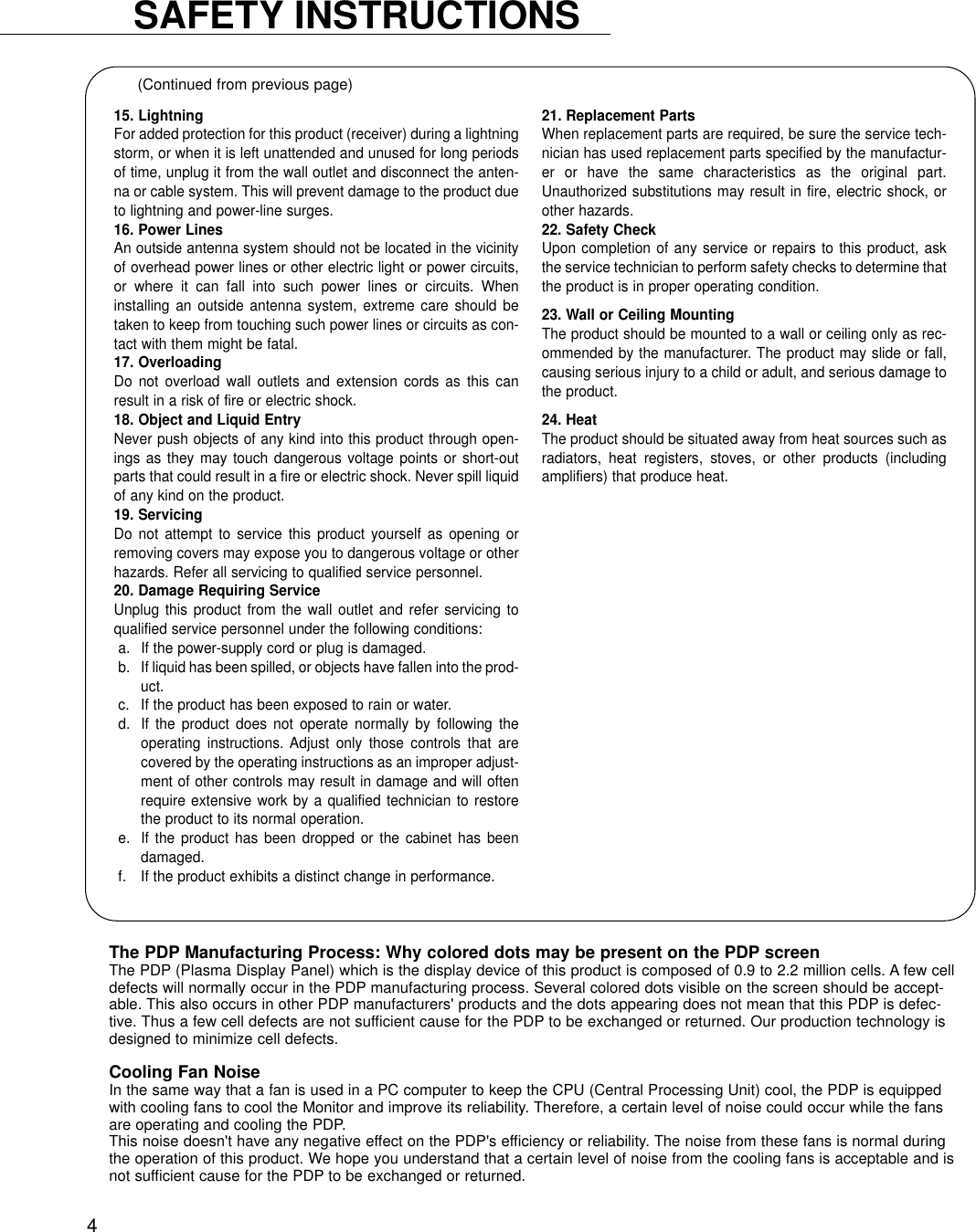
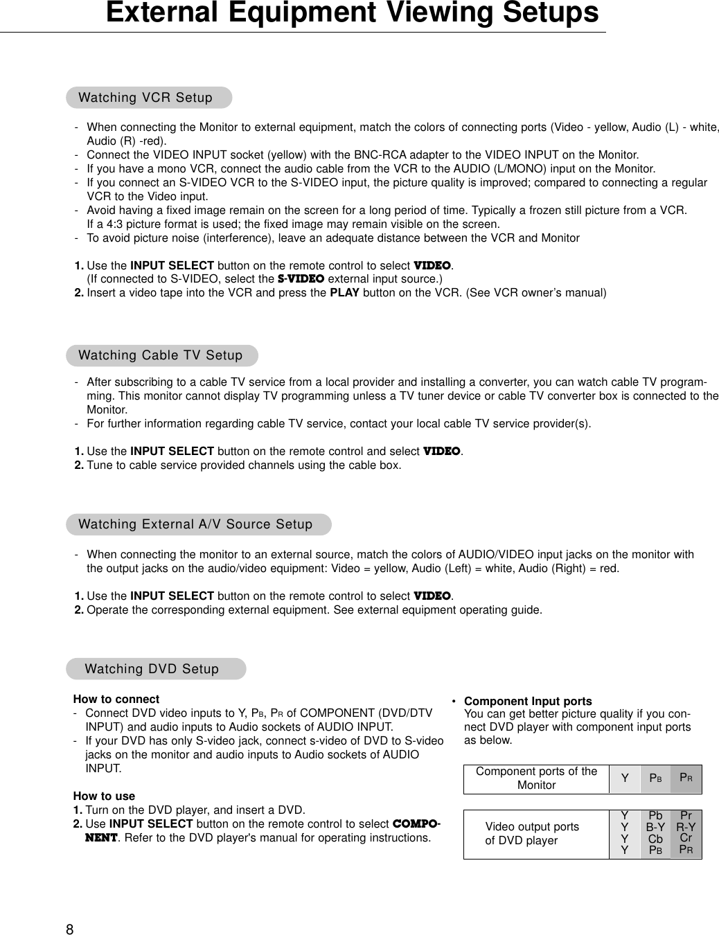
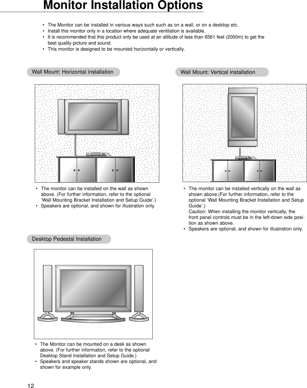
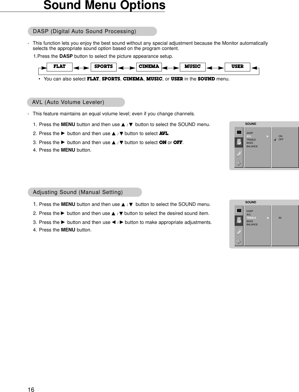
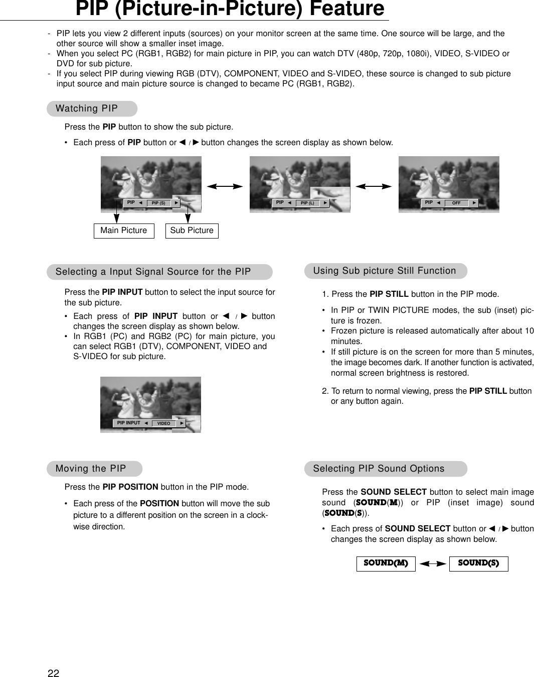
![2605. Volume Mute (Command2:e)GTo control volume mute on/off.You can also adjust mute using the MUTE button onremote control.TransmissionData 0 : Volume mute on (Volume off)1 : Volume mute off (Volume on)[k][e][ ][Set ID][ ][Data][Cr]Acknowledgement[e][ ][Set ID][ ][OK][Data][x]03. Aspect Ratio (Command2:c) (Main picture format)GTo adjust the screen format.You can also adjust the screen format using the ARC(Aspect Ratio Control) button on remote control or in thescreen menu.TransmissionData 0 : Wide screen (16:9)1 : Normal screen (4:3) 2 : Full screen (Zoom) [k][c][ ][Set ID][ ][Data][Cr]AcknowledgementData 0 : Wide screen (16:9)1 : Normal screen (4:3) 2 : Full screen (Zoom) * Using the PC input, you select either 16:9 or 4:3 screenaspect ratio.[c][ ][Set ID][ ][OK][Data][x]04. Screen Mute (Command2:d)GTo select screen mute on/off.TransmissionData 0 : Screen mute off (Picture on)1 : Screen mute on (Picture off)[k][d][ ][Set ID][ ][Data][Cr]Acknowledgement[d][ ][Set ID][ ][OK][Data][x]06. Volume Control (Command2:f)GTo adjust volume.You can also adjust volume with the volume buttonson remote control.TransmissionData Min : 0 ~ Max : 64* Refer to ‘Real data mapping1’. See page 29.[k][f][ ][Set ID][ ][Data][Cr]Acknowledgement[f][ ][Set ID][ ][OK][Data][x]07. Contrast (Command2:g)GTo adjust screen contrast. You can also adjust contrast in the picture menu.TransmissionData Min : 0 ~ Max : 64* Refer to ‘Real data mapping1’. See page 29.[k][g][ ][Set ID][ ][Data][Cr]Acknowledgement[g][ ][Set ID][ ][OK][Data][x]02. Input Select (Command2:b) (Main Picture Input)GTo select input source for the Monitor. You can also select an input source using the INPUTSELECT button on the Monitor's remote control.TransmissionData 0 : RGB 11 : COMPONENT2 : VIDEO3 : S-VIDEO4 : RGB 2[k][b][ ][Set ID][ ][Data][Cr]Acknowledgement[b][ ][Set ID][ ][OK][Data][x]01. Power (Command2:a)GTo control Power On/Off of the Monitor.TransmissionData 0 : Power Off 1 : Power On[k][a][ ][Set ID][ ][Data][Cr]Acknowledgement[a][ ][Set ID][ ][OK][Data][x]GTo show Power On/Off.Transmission[k][a][ ][Set ID][ ][FF][Cr]AcknowledgementData 0 : Power Off 1 : Power On* In like manner, if other functions transmit ‘FF’data basedon this format, Acknowledgement data feed back presentsstatus about each function.[a][ ][Set ID][ ][OK][Data][x]](https://usermanual.wiki/LG-Electronics-USA/MU42PZ41V/User-Guide-290708-Page-26.png)
![2709. Color (Command2:i)GTo adjust the screen color.You can also adjust color in the picture menu.TransmissionData Min : 0 ~ Max : 64* Refer to ‘Real data mapping1’. See page 29.[k][i][ ][Set ID][ ][Data][Cr]Acknowledgement[i][ ][Set ID][ ][OK][Data][x]08. Brightness (Command2:h)GTo adjust screen brightness.You can also adjust brightness in the picture menu.TransmissionData Min : 0 ~ Max : 64* Refer to ‘Real data mapping1’. See page 29.[k][h][ ][Set ID][ ][Data][Cr]Acknowledgement[h][ ][Set ID][ ][OK][Data][x]13. Remote Control Lock Mode (Command2:m)GTo lock the front panel controls on the monitor and remotecontrol.Transmission[k][m][ ][Set ID][ ][Data][Cr]AcknowledgementData 0 : Lock off 1 : Lock on* If you’re not using the remote control, use this mode.When main power is on/off, remote control lock is released.[m][ ][Set ID][ ][OK][Data][x]GTo adjust the screen sharpness.You can also adjust sharpness in the picture menu.Transmission11. Sharpness (Command2:k)Data Min : 0 ~ Max : 64* Refer to ‘Real data mapping1’. See page 29.[k][k][ ][Set ID][ ][Data][Cr]Acknowledgement[k][ ][Set ID][ ][OK][Data][x]12. OSD Select (Command2:l)GTo select OSD (On Screen Display) on/off.Transmission[k][l][ ][Set ID][ ][Data][Cr]AcknowledgementData 0 : OSD off 1 : OSD on[l][ ][Set ID][ ][OK][Data][x]10. Tint (Command2:j)GTo adjust the screen tint.You can also adjust tint in the picture menu.TransmissionData Red : 0 ~ Green : 64* Refer to ‘Real data mapping1’. See page 29.[k][j][ ][Set ID][ ][Data][Cr]Acknowledgement[j][ ][Set ID][ ][OK][Data][x]14. PIP / Twin (DW) (Command2:n)GTo control the PIP (Picture In picture). You can also control the PIP/TWIN using the PIP or Twinpicture button on the remote control or in the screen menu.TransmissionData 0: PIP/DW off1: PIP (S)2: DW13: DW24: PIP (L)[k][n][ ][Set ID][ ][Data][Cr]Acknowledgement[n][ ][Set ID][ ][OK][Data][x]15. PIP Sound Select (Command2:p)GTo select main or sub sound for PIP. You can also adjust main or sub sound for PIP using PIPSOUND button on the remote control or in the screenmenu.Transmission[k][p][ ][Set ID][ ][Data][Cr]AcknowledgementData 0: Main image sound1: Sub image sound[p][ ][Set ID][ ][OK][Data][x]](https://usermanual.wiki/LG-Electronics-USA/MU42PZ41V/User-Guide-290708-Page-27.png)
![2821. Red Adjustment (Command2:v)GTo adjust red in color temperature.TransmissionData Min : 0 ~ Max : 64* Refer to ‘Real data mapping 2’. See page 29.[k][v][ ][Set ID][ ][Data][Cr]Acknowledgement[v][ ][Set ID][ ][OK][Data][x]22. Green Adjustment (Command2:w)GTo adjust green in color temperature.TransmissionData Min : 0 ~ Max : 64* Refer to ‘Real data mapping 2’. See page 29.[k][w][ ][Set ID][ ][Data][Cr]Acknowledgement[w][ ][Set ID][ ][OK][Data][x]23. Blue Adjustment (Command2:$)GTo adjust blue in color temperature.TransmissionData Min : 0 ~ Max : 64* Refer to ‘Real data mapping 2’. See page 29.Data Min : 0 ~ Max : 64[k][$][ ][Set ID][ ][Data][Cr]Acknowledgement[$][ ][Set ID][ ][OK][Data][x]20. Color Temperature (Command2:u)GTo adjust color temperature.You can also adjust ACC in the special menu.TransmissionData 0: Normal 1: Cool 2: Warm 3: User[k][u][ ][Set ID][ ][Data][Cr]Acknowledgement[u][ ][Set ID][ ][OK][Data][x]18. Bass (Command:s)GTo adjust bass.You can also adjust bass in the sound menu.TransmissionData Min : 0 ~ Max : 64* Refer to ‘Real data mapping1’. See page 29.[k][s][ ][Set ID][ ][Data][Cr]Acknowledgement[s][ ][Set ID][ ][OK][Data][x]19. Balance (Command2:t)GTo adjust balance.You can also adjust balance in the sound menu.TransmissionData Min : 0 ~ Max : 64* Refer to ‘Real data mapping1’. See page 29.[k][t][ ][Set ID][ ][Data][Cr]AcknowledgementData Min : 0 ~ Max : 64[t][ ][Set ID][ ][OK][Data][x]17. Treble (Command2:r)GTo adjust treble.You can also adjust treble in the sound menu.TransmissionData Min : 0 ~ Max : 64* Refer to ‘Real data mapping1’. See page 29.[k][r][ ][Set ID][ ][Data][Cr]Acknowledgement[r][ ][Set ID][ ][OK][Data][x]16. PIP Position (Command2:q)GTo select sub picture position for PIP. You can also adjust the sub picture position using PIPPOSITION on the remote control or in the screen menu.TransmissionData 0 : Right down on screen1 : Left down on screen2 : Left up on screen3 : Right up on screen[k][q][ ][Set ID][ ][Data][Cr]Acknowledgement[q][ ][Set ID][ ][OK][Data][x]](https://usermanual.wiki/LG-Electronics-USA/MU42PZ41V/User-Guide-290708-Page-28.png)
![2925. Orbiter (Command2:p)GTo control the orbiter function on/off.TransmissionData 0 : Orbiter off1 : Orbiter on[j][p][ ][Set ID][ ][Data][Cr]Acknowledgement[p][ ][Set ID][ ][OK][Data][x]26. White Wash (Command2:q)GTo control the white wash function on/off.TransmissionData 0 : White Wash off1 : White Wash on[j][q][ ][Set ID][ ][Data][Cr]Acknowledgement[q][ ][Set ID][ ][OK][Data][x]24. PIP Input Select (Command2:y)G To select input source for sub picture in PIP mode.TransmissionData 0: RGB1 (DTV)1: COMPONENT2: VIDEO3: S-VIDEO[k][y][ ][Set ID][ ][Data][Cr]Acknowledgement[y][ ][Set ID][ ][OK][Data][x]* Real data mapping 10 : Step 0A : Step 10 (SET ID 10)F : Step 15 (SET ID 15)10 : Step 16 (SET ID 16)64 : Step 100* Real data mapping 20 : -105: -9A: -82D: -132: 037: +15F: +964: +10](https://usermanual.wiki/LG-Electronics-USA/MU42PZ41V/User-Guide-290708-Page-29.png)