LG Electronics USA MU60PZ12M 60" Plasma Monitor User Manual 0277W edit1
LG Electronics USA 60" Plasma Monitor 0277W edit1
UserManual.wiki
>
LG Electronics USA
>
MU60PZ12M User Manual
users manual
Navigation menu
Upload a User Manual
Namespaces
Wiki Guide
HTML
PDF
Info
Views
User Manual
Discussion / Help
Navigation

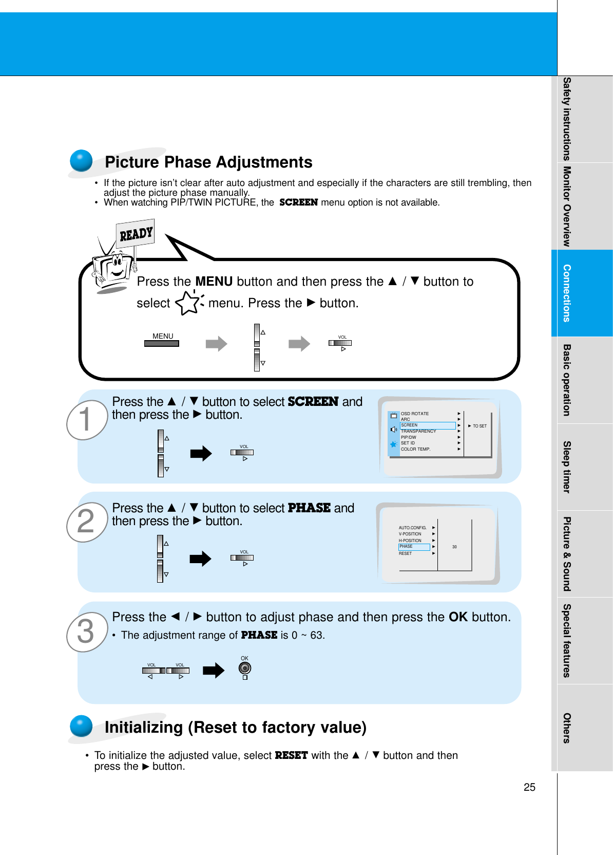
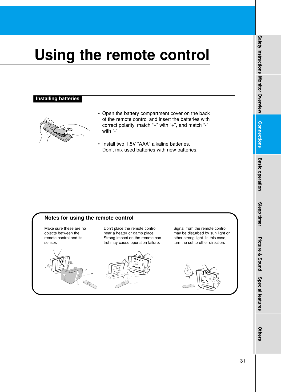
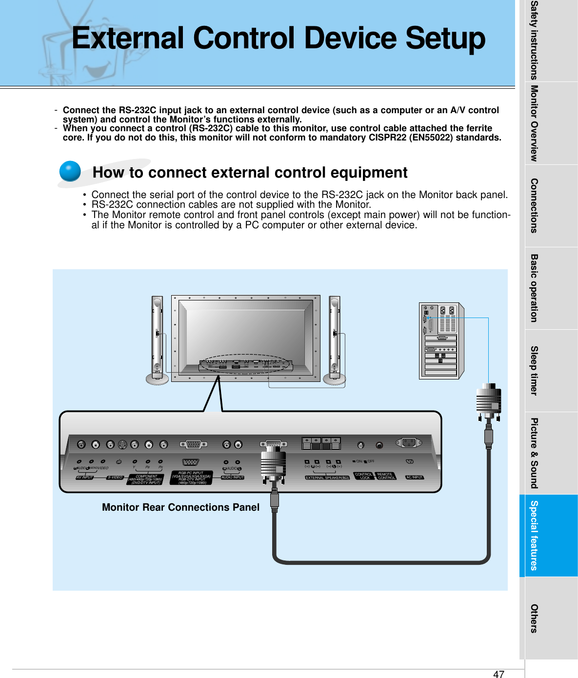
![26Picture In Picture (PIP) function- PIP lets you view 2 different inputs (sources) on your monitor screen at the same time. One source willbe large, and the other source will show a smaller inset image.- Select RGB input source before pressing PIP.- This function works only in the following resolutions; 640x480, 800x600, 1024x768 (only in Vertical frequency 60 Hz)- When you select RGB or DTV for main picture in PIP/Twin picture, you can watch video, cable TV orDVD for sub picture.- Color of main picture may be different from PIP’s in PIP/Twin picture mode.- If input source for main picture is changed while in PIP/Twin picture mode, sub picture will disappear.- When watching PIP/Twin picture, SCREEN option is not available in Special menu.- With PIP active, not all picture formats can be used for the main/sub picture.Watching the PIP (Picture in Picture)Press the PIP button.•Each time you press PIP or F /Gbutton, you can change thePIP size as below.PIP[S] PIP [L] OFFPIPF PIP [S] GPIPF PIP [L] GPIPF OFFG<Small PIP><Large PIP><Off>PIP](https://usermanual.wiki/LG-Electronics-USA/MU60PZ12M/User-Guide-279948-Page-26.png)
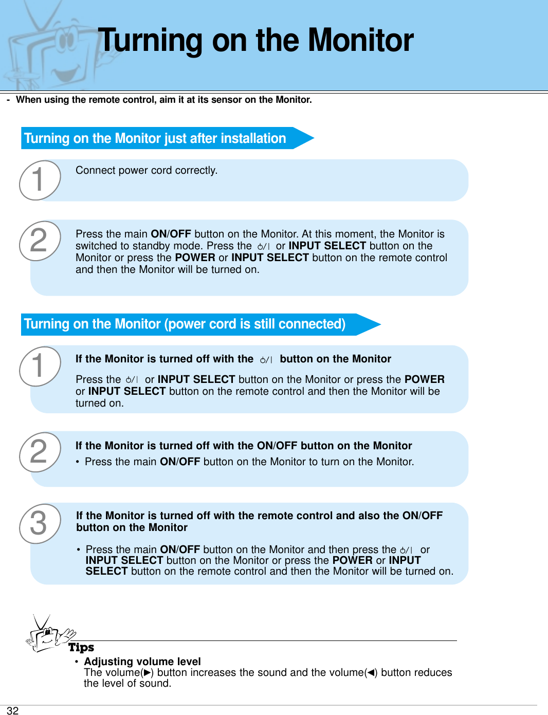
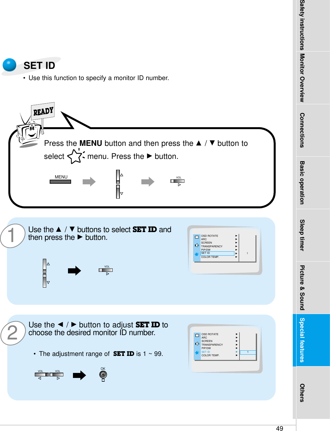
![28321Use the D / Ebuttons to select PIP/DW andthen press the Gbutton.READYPress the D / Ebutton to select SOUNDSELECT and then press the Gbutton.•Each time you press D / E button, you togglebetween SOUND [M] or SOUND [S].Press the D / Ebuttons to select mainimage sound (SOUND [M]) or PIP (insetimage) sound (SOUND [S]) and then pressthe OK button.LANGUAGEGCAPTIONGAUTO OFFGSCREENGRGB-OUTPUTGDWGPIPGINPUTGSOUND SELECTGPOSITIONGSOUND [M]SOUND [S]SOUND SELECTLANGUAGEGCAPTIONGAUTO OFFGSCREENGRGB-OUTPUTGDWGPIPGINPUTGSOUND SELECTGPOSITIONGSOUND [M]SOUND [S]OSD ROTATE GARC GSCREEN GTRANSPARENCY GPIP/DW GSET ID GCOLOR TEMP. GG TO SETPIP/DW- To select main or sub (inset) sound- This function only works with the following resolutions; 640x480, 800x600, 1024x768 (only in Vertical frequency 60 Hz)- To use this function, connect PC/DTV video output to RGB-PC INPUT/RGB-DTV INPUT and connect PC/DTVaudio outputs to AUDIO INPUT.-SOUND SELECT is always the main picture sound (SOUND[M]) regardless of prior sound choice.Selecting PIP sound optionsSOUND [S]Picture In Picture (PIP) functionMENUVOLVOLVOLOKPress the MENU button and then press the D / Ebutton toselect menu. Press the Gbutton.](https://usermanual.wiki/LG-Electronics-USA/MU60PZ12M/User-Guide-279948-Page-28.png)
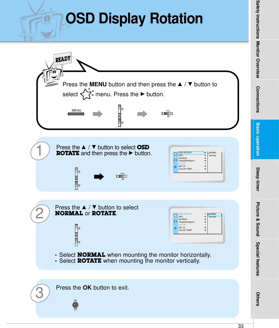
![50External Control Device SetupCommunication ParametersCommand Reference List-The RS-232C input jack is used to control the Monitor’s functions using an external control device.•Baud rate : 2400 bps (UART)•Data length : 8 bits•Parity : None•Stop bit : 1 bit•Communication code : ASCII code* If the command interval is interrupted for more than 4seconds, only Command 1 will be recognized.Be careful when using the power command.Transmission* [Command] : To control PDP set.* [Set ID] : You can adjust the set ID to choose desired monitor ID number in special menu. See page 49. Adjustment range is 1 ~ 99. When selecting Set ID ‘0’, every connectedPDP set is controlled.* [DATA] : To transmit command data.Transmit ‘FF’data to read status of command.* [Cr] : Carriage ReturnASCII code ‘0x0D’* [ ] : ASCII code ‘space (0x20)’[Command][ ][Set ID][ ][Data][Cr]OK Acknowledgement* The Monitor transmits ACK (acknowledgement) basedon this format when receiving normal data. At thistime, if the data is data read mode, it indicates presentstatus data. If the data is data write mode, it returnsthe data of the PC computer.[Set ID][:][OK][x][Data][x]Error Acknowledgement* The Monitor transmits ACK (acknowledgement) basedon this format when receiving abnormal data from non-viable functions or communication errors.[Set ID][:][NG][x]Transmission / Receiving ProtocolNAME COMMAND DATA RANGE01. Power p 0 ~ 102. Input Select i 0 ~ 303. Aspect Ratio r 0 ~ 204. Screen mute m 0 ~ 105. Volume mute w 0 ~ 106. Volume control v 0 ~ 6407. Contrast k 0 ~ 6408. Brightness b 0 ~ 6409. Color c 0 ~ 6410. Tint t 0 ~ 6411. Sharpness s 0 ~ 6412. OSD select d 0 ~ 113. Abnormal state a 0 ~ 114. PIP/DW z 0 ~ 315. PIP input select e 0 ~ 116. PIP sound select u 0 ~ 117. PIP position x 0 ~ 318. remote control j 0 ~ 1adjustment mode](https://usermanual.wiki/LG-Electronics-USA/MU60PZ12M/User-Guide-279948-Page-50.png)
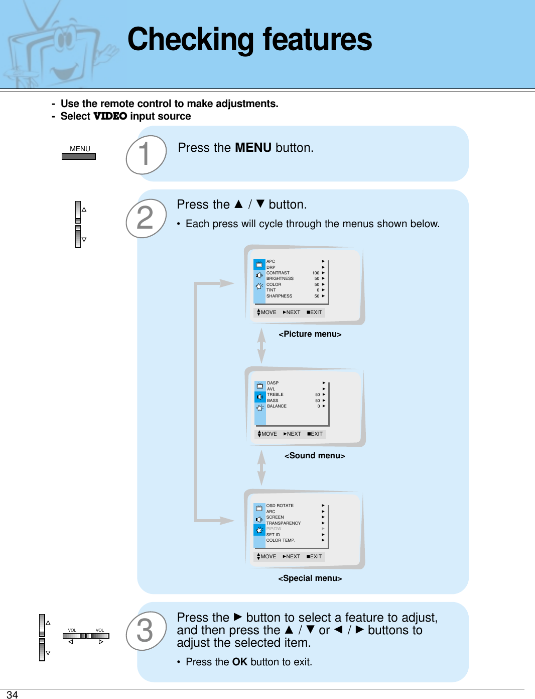
![51Safety instructions Monitor Overview Connections Basic operation Sleep timer Picture & Sound Special features Others01. Power (Command:p)GTo control Power On/Off of the Monitor.TransmissionData 0 : Power Off1 : Power On * Example : Power on for set ID No.3.Type : P 3 1 ‘0x0D’[p][ ][Set ID][ ][Data][Cr]AcknowledgementData 0 : Power Off1 : Power On * In example : Monitor Acknowledges power on for set IDNo.3.[Set ID][:][OK][x][Data][x]02. Input select (Command:i)GTo select input source for the Monitor. You can also select an input source using the INPUTSELECT button on the Monitor's remote control.TransmissionData 0 : RGB1 : AV (Video)2 : Component3 : S-AV (S-Video)[i][ ][Set ID][ ][Data][Cr]AcknowledgementData 0 : RGB1 : AV (Video)2 : Component3 : S-AV (S-Video)[Set ID][:][OK][x][Data][x]GTo show Power On/Off.Transmission[p][ ][Set ID][ ][FF][Cr]AcknowledgementData 0 : Power Off1 : Power On (RGB)2 : Power On (Video)3 : Power On (Component)4 : Power On (S-Video)* In like manner, if other functions transmit ‘FF’databased on this format, Acknowledgement data feedback presents status about each function.[Set ID][:][OK][x][Data][x]03. Aspect Ratio (Command:r)GTo adjust the screen format.You can also adjust the screen format using the ARC(Aspect Ratio Control) button on remote control or inthe Special menu.TransmissionData 0 : Wide screen (16:9)1 : Normal screen (4:3) 2 : Full screen (Zoom) [r][ ][Set ID][ ][Data][Cr]AcknowledgementData 0 : Wide screen (16:9)1 : Normal screen (4:3) 2 : Full screen (Zoom) * Using the PC input, you select either 16:9 or 4:3 screenaspect ratio.* Using the DTV 720p/1080i input, you can only select16:9 screen aspect ratio.[Set ID][:][OK][x][Data][x]04. Screen mute (Command:m)GTo select screen mute on/off.TransmissionData 0 : Screen mute on (Picture off)1 : Screen mute off (Picture on)[m][ ][Set ID][ ][Data][Cr]AcknowledgementData 0 : Screen mute on (Picture off)1 : Screen mute off (Picture on)[Set ID][:][OK][x][Data][x]05. Volume mute (Command:w)GTo control volume mute on/off.You can also adjust mute using the MUTE button onremote control.TransmissionData 0 : Volume mute on (Volume off)1 : Volume mute off (Volume on)[w][ ][Set ID][ ][Data][Cr]AcknowledgementData 0 : Volume mute on (Volume off)1 : Volume mute off (Volume on)[Set ID][:][OK][x][Data][x]](https://usermanual.wiki/LG-Electronics-USA/MU60PZ12M/User-Guide-279948-Page-51.png)
![52External Control Device Setup* Real data mapping0 : Step 0A : Step 10F : Step 1510 : Step 1664 : Step 10006. Volume control (Command:v)GTo adjust volume.You can also adjust volume with the volume buttonson remote control.TransmissionData Min : 0 ~ Max : 64* Refer to ‘Real data mapping’as shown below.[v][ ][Set ID][ ][Data][Cr]AcknowledgementData Min : 0 ~ Max : 64[Set ID][:][OK][x][Data][x]07. Contrast (Command:k)GTo adjust screen contrast. You can also adjust contrast in the Picture menu.TransmissionData Min : 0 ~ Max : 64* Refer to ‘Real data mapping’as shown below.[k][ ][Set ID][ ][Data][Cr]AcknowledgementData Min : 0 ~ Max : 64[Set ID][:][OK][x][Data][x]08. Brightness (Command:b)GTo adjust screen brightness.You can also adjust brightness in the Picture menu.TransmissionData Min : 0 ~ Max : 64* Refer to ‘Real data mapping’as shown below.[b][ ][Set ID][ ][Data][Cr]AcknowledgementData Min : 0 ~ Max : 64[Set ID][:][OK][x][Data][x]09. Color (Command:c)GTo adjust the screen color.You can also adjust color in the Picture menu.TransmissionData Min : 0 ~ Max : 64* Refer to ‘Real data mapping’as shown below.[c][ ][Set ID][ ][Data][Cr]AcknowledgementData Min : 0 ~ Max : 64[Set ID][:][OK][x][Data][x]10. Tint (Command:t)GTo adjust the screen tint.You can also adjust tint in the Picture menuTransmissionData Red : 0 ~ Green : 64* Refer to ‘Real data mapping’as shown below.[t][ ][Set ID][ ][Data][Cr]AcknowledgementData Red : 0 ~ Green : 64[Set ID][:][OK][x][Data][x]11. Sharpness (Command:s)GTo adjust the screen sharpness.You can also adjust sharpness in the Picture menuTransmissionData Min : 0 ~ Max : 64* Refer to ‘Real data mapping’as shown below.[s][ ][Set ID][ ][Data][Cr]AcknowledgementData Min : 0 ~ Max : 64[Set ID][:][OK][x][Data][x]](https://usermanual.wiki/LG-Electronics-USA/MU60PZ12M/User-Guide-279948-Page-52.png)
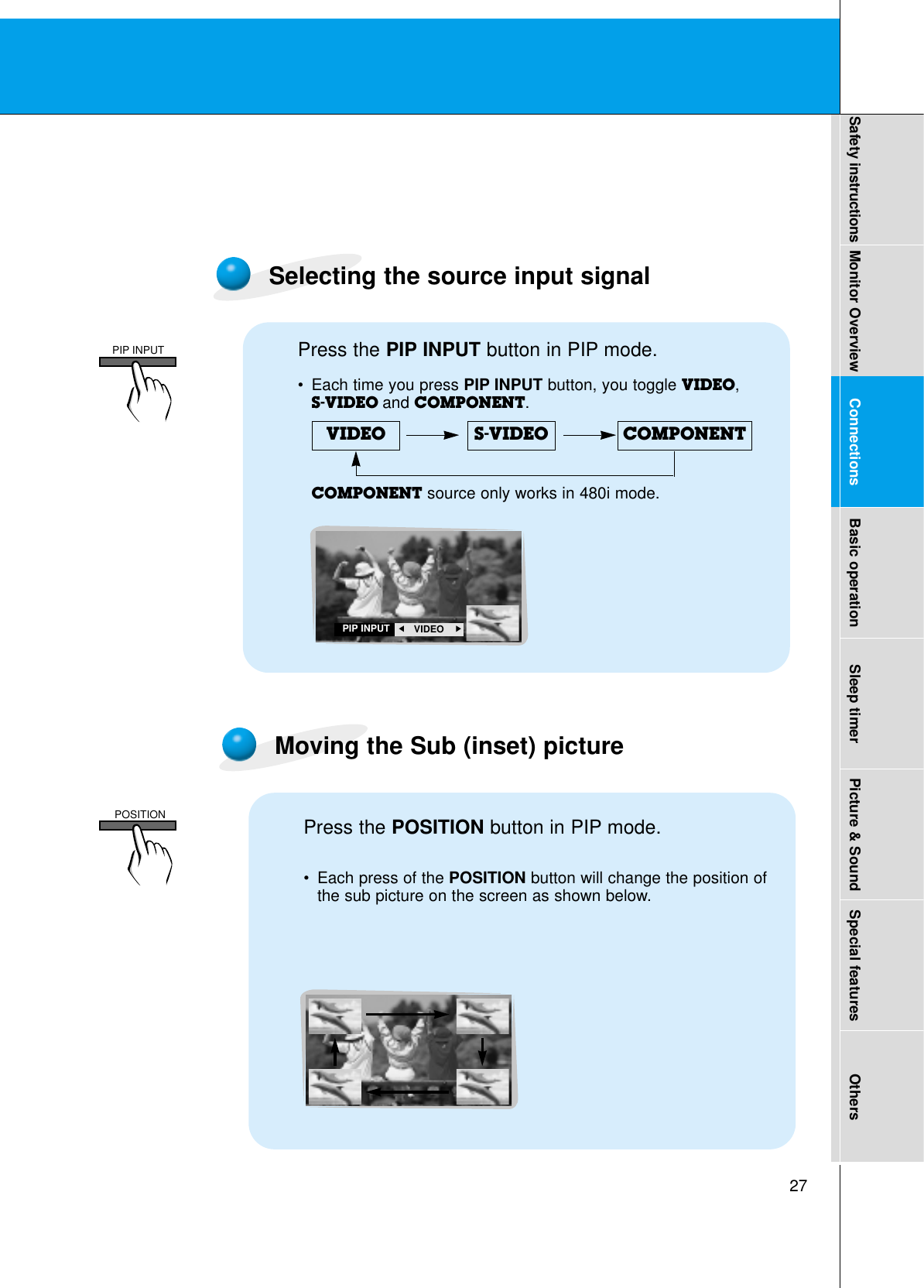
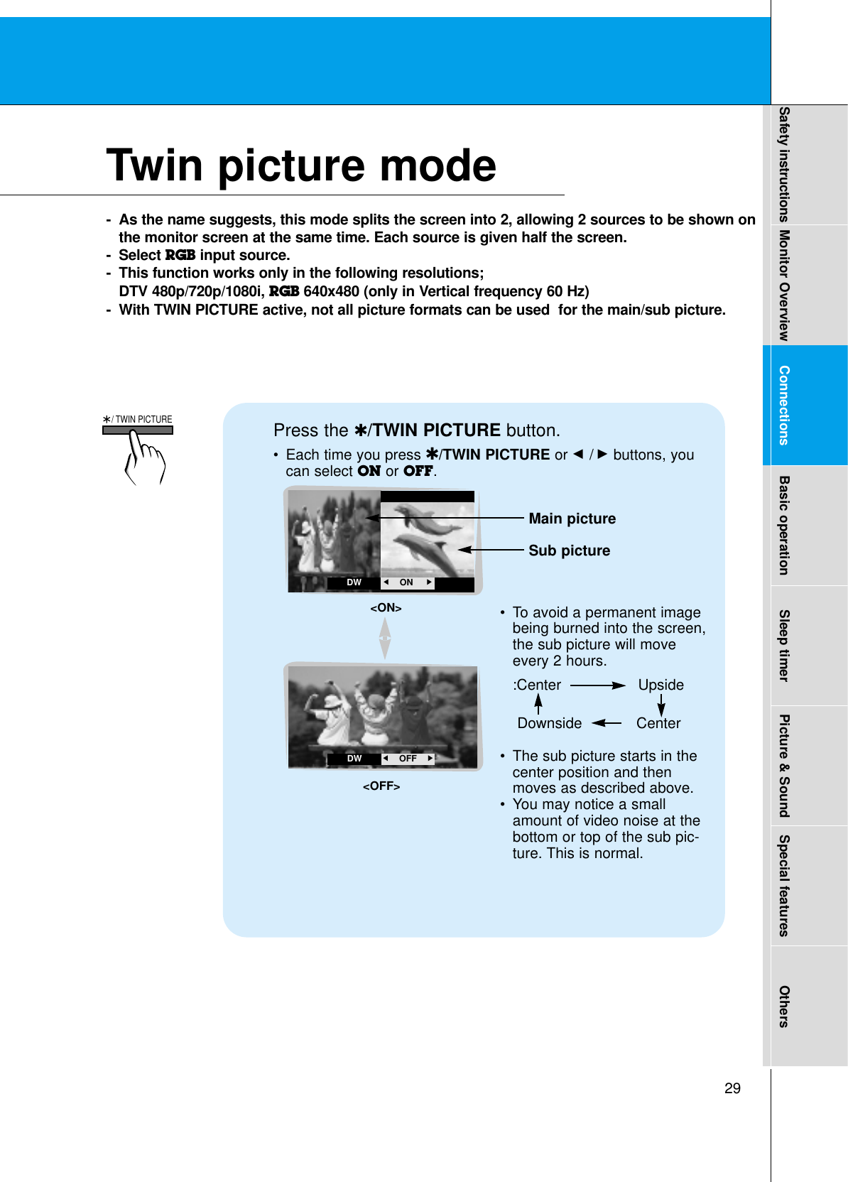
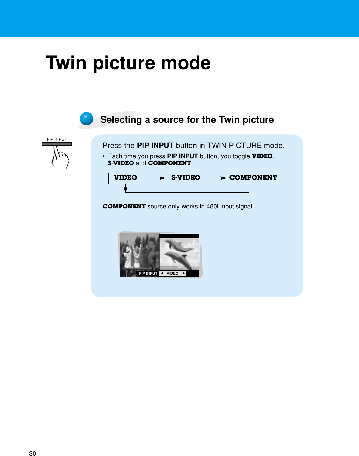
![53Safety instructions Monitor Overview Connections Basic operation Sleep timer Picture & Sound Special features Others12. OSD select (Command:d)GTo select OSD (On Screen Display) on/off.Transmission* The remote control and Monitor front panel controls(except main power) are not operable when the Monitoris set up to be controlled by the PC computer.* This function is “read only”.Data 0 : OSD off1 : OSD on[d][ ][Set ID][ ][Data][Cr]AcknowledgementData 0 : OSD off1 : OSD on[Set ID][:][OK][x][Data][x]13. Abnormal state (Command:a)GTo recognize an abnormal state. Transmission[a][ ][Set ID][ ][FF][Cr]AcknowledgementData 0 : OK1 : Fan alarm2 : 5V down3 : AC down[Set ID][:][OK][x][Data][x]14. PIP / DW (Command:z)GTo control PIP (Picture-in-Picture) or twin picture (DW).You can also control PIP/DW using the pip/twin picturebutton on remote control or in the Special menu.TransmissionData 0 : PIP/ DW off1 : PIP (small)2 : PIP (large)3 : Twin picture (DW)[z][ ][Set ID][ ][Data][Cr]AcknowledgementData 0 : PIP/ DW off1 : PIP (small)2 : PIP (large)3 : Twin picture (DW)* PIP only works in the following resolutions:RGB PC 640x480 (VGA) / 800x600(SVGA) / 1024x768(XGA) (only in vertical frequency 60Hz), Component 480p / 720p / 1080i.* Twin picture works only in the following resolutions:RGB PC 640x480 (VGA) (only in vertical frequency 60Hz), RGB DTV, Component 480p/720p/1080i.[Set ID][:][OK][x][Data][x]15. PIP input select (Command:e)G To select input source for sub picture in PIP mode.You can also select source using PIP input button onthe remote control or in the Special menu.Transmission* COMPONENT source only works with 480i input signal.Data 0 : VIDEO1 : COMPONENT2 : S-VIDEO[e][ ][Set ID][ ][Data][Cr]AcknowledgementData 0 : VIDEO1 : COMPONENT2 : S-VIDEO[Set ID][:][OK][x][Data][x]](https://usermanual.wiki/LG-Electronics-USA/MU60PZ12M/User-Guide-279948-Page-53.png)
![54* COMPONENT source only works in 480i input signal.16. PIP sound select (Command:u)G To select main or sub (inset) sound for PIP/Twin picture.You can also select sound select in PIP/DW on the special menu.Transmission[u][ ][Set ID][ ][Data][Cr]AcknowledgementData 0 : Main picture sound1 : Sub picture soundData 0 : Main picture sound1 : Sub picture sound[Set ID][:][OK][x][Data][x]* If external equipment commands the Monitor to"change into remote control adjustment mode", theMonitor can only be adjusted by the remote control. To revert the Monitor control to external control deviceadjustment, turn the Monitor off and then on again.18. Change into Remote controladjustment mode (Command:j)G To control the Monitor with the remote control whilethe cable is still connected. Transmission[j][ ][Set ID][ ][Data][Cr]AcknowledgementData 0 : PC adjustment mode1 : Remote control adjustment modeData 1 : Remote control adjustment mode[Set ID][:][OK][x][Data][x]17. PIP position (Command:x)GTo select sub picture position for PIP. You can also adjust the sub picture position using theposition button on the remote control or in PIP/DW onthe Special menu.TransmissionData 0 : Right down on screen1 : Left down on screen2 : Left up on screen3 : Right up on screen[x][ ][Set ID][ ][Data][Cr]AcknowledgementData 0 : Right down on screen1 : Left down on screen2 : Left up on screen3 : Right up on screen[Set ID][:][OK][x][Data][x]External Control Device Setup](https://usermanual.wiki/LG-Electronics-USA/MU60PZ12M/User-Guide-279948-Page-54.png)