LG Electronics USA MU60PZ12M 60" Plasma Monitor User Manual 0277W edit1
LG Electronics USA 60" Plasma Monitor 0277W edit1
users manual
PLASMA MONITOR
ON/OFF INPUT
SELECT VOLUME
P/NO : 3828VA0277W
(NP00KB)
PLASMA MONITOR
Please read this owner’s manual carefully before
operating the Monitor.
Retain it for future reference.
Record model number and serial number of the
Monitor.
See the label attached on the back of the Monitor
and quote this information to your dealer when you
require service.
Model number :
Serial number :
MU-60PZ12M/12V
MU-60PZ12MA/12VA
MU-60PZ12MB/12VB
MU-60PZ12MK/12VK
MU-60PZ12MS/12VS
OWNER’S MANUAL
a

ON/OFF INPUT
SELECT VOLUME
WARNING
TO REDUCE THE RISK OF FIRE AND ELECTRIC SHOCK, DO NOT EXPOSE THIS PROD-
UCT TO RAIN OR MOISTURE.
The explanation about colored dots may be present on PDP screen
The PDP which is the display device of this product is composed of 0.9 to 2.2 million cells and a few cell
defects can occur in the manufacture of the PDP. Several colored dots visible on the screen would be
acceptable, in line with other PDP manufacturers and would not mean that the PDP is faulty. We hope you
will understand that the product which corresponds to this standard is regarded as acceptable. It means
that it could not be changed or refunded.
We promise that we'll do our best to develop our technology to minimize the cell defects.
The explanation about noise of 60" PDP
In the same way that a fan is used in a PC to keep the CPU cool, the PDP is equipped with cooling fans to
improve the reliability of this product. Therefore, a certain level of noise could occur when the fan is oper-
ated. This noise doesn't have any negative effect on its efficiency and liability and it's also determined to
have no difficulty while using this product. The noise from the fans is normal in the operation of this prod-
uct. We hope you will understand that a certain level of noise is acceptable. It means that it is not change-
able nor refundable.
FCC NOTICE
• MU-60PZ12M/MA/MB/MK/MS, MU-60PZ12V/VA/VB/VK/VS : A Class B digital device
This equipment has been tested and found to comply with the limits for a Class B digital device, pursuant
to Part 15 of the FCC Rules. These limits are designed to provide reasonable protection against harmful
interference in a residential installation. This equipment generates, uses and can radiate radio frequency
energy and, if not installed and used in accordance with the instructions, may cause harmful interference
to radio communications. However, there is no guarantee that interference will not occur in a particular
installation. If this equipment does cause harmful interference to radio or television reception, which can
be determined by turning the equipment off and on, the user is encouraged to try to correct the interfer-
ence by one or more of the following measures:
- Reorient or relocate the receiving antenna.
- Increase the separation between the equipment and receiver.
- Connect the equipment into an outlet on a circuit different from that to which the receiver is connected.
- Consult the dealer or an experienced radio/TV technician for help.
Earth wire should be connected.
- If the earth wire is not connected, there is possible a danger of electric shock caused by the current leakage.
- If grounding methods are not possible, a separate circuit breaker should be employed and installed by a
qualified electrician.
- Do not connect ground to telephone wires, lightning rods or gas pipe.

Keep this manual
with Monitor for
future easy refer-
ence)
Table of Contents
First step
WARNINGS..............................................................4
SAFETY INSTRUCTIONS........................................5
Monitor Overview
Front Panel Controls ................................................8
Connection Panel Overview .....................................9
Remote Control Key Functions/Accessories..........10
Monitor Installation .................................................12
Equipment Connections and Setup
VCR Setup..............................................................14
Cable TV Setup ......................................................16
External AV Source Setup......................................17
DVD Setup..............................................................18
DTV Setup..............................................................19
PC Setup ................................................................20
PC Mode Feature Check(Overview) ......................22
PC Mode Adjustments............................................23
Picture In Picture (PIP) function .............................26
Twin picture function...............................................29
Using the remote control ........................................31
Basic Features Setup and Operation
Turning on the Monitor ...........................................32
OSD Display Rotation ............................................33
Checking features...................................................34
Sleep Timer
Setting Sleep Timer (Monitor turn-off time) ............35
Picture & Sound
Auto picture control ................................................36
Adjusting picture appearance.................................37
DRP (Digital Reality Picture) ..................................38
Adjusting Sound: Bass, Treble, Balance................39
Auto Sound Control ................................................40
AVL (Auto volume leveler)......................................41
Special Features
Using Still function..................................................42
Using the screen options........................................43
Adjusting OSD Transparency.................................44
Adjusting color temperature ...................................45
Setting picture format .............................................46
External control device setup .................................47
IR Code (NEC format)............................................55
Others
Maintenance ...........................................................57
Troubleshooting check list......................................58
Product specifications.............................................59
4
WARNINGS
WARNING:
TO REDUCE THE RISK OF ELECTRIC SHOCK DO NOT REMOVE COVER
(OR BACK). NO USER SERVICEABLE PARTS INSIDE.
REFER TO QUALIFIED SERVICE PERSONNEL.
The lightning flash with arrowhead symbol, within an equilateral triangle, is
intended to alert the user to the presence of uninsulated “dangerous voltage”
within the product’s enclosure that may be of sufficient magnitude to consti-
tute a risk of electric shock to persons.
The exclamation point within an equilateral triangle is intended to alert the
user to the presence of important operating and maintenance (servicing)
instructions in the literature accompanying the appliance.
WARNING:
TO PREVENT FIRE OR SHOCK HAZARDS, DO NOT EXPOSE THIS PRODUCT TO
RAIN OR MOISTURE.
CAUTION:
TO PREVENT ELECTRIC SHOCK, MATCH WIDE BLADE OF PLUG TO WIDE SLOT,
FULLY INSERT.
WARNING
RISK OF ELECTRIC SHOCK
DO NOT OPEN
5
Safety instructions Monitor Overview Connections Basic operation Sleep timer Picture & Sound Special features Others
Important safeguards for you and your new product
Your product has been manufactured and tested with your safety in mind. However, improper
use can result in potential electrical shock or fire hazards. To avoid defeating the safeguards
that have been built into your new product, please read and observe the following safety
points when installing and using your new product, and save them for future reference.
Observing the simple precautions discussed in this booklet can help you get many years of
enjoyment and safe operation that are built into your new product.
This product complies with all applicable U.S. Federal safety requirements, and those of the
Canadian Standards Association.
1. Read Instructions
All the safety and operating instructions
should be read before the product is operat-
ed.
2. Follow Instructions
All operating and use instructions should be
followed.
3. Retain Instructions
The safety and operating instructions should
be retained for future reference.
4. Heed Warnings
All warnings on the product and in the oper-
ating instructions should be adhered to.
5. Cleaning
Unplug this product from the wall outlet
before cleaning. Do not use liquid cleaners
or aerosol cleaners. Use a damp cloth for
cleaning.
6. Water and Moisture
Do not use this product near water, for
example, near a bath tub, wash bowl,
kitchen sink, or laundry tub, in a wet base-
ment, or near a swimming pool.
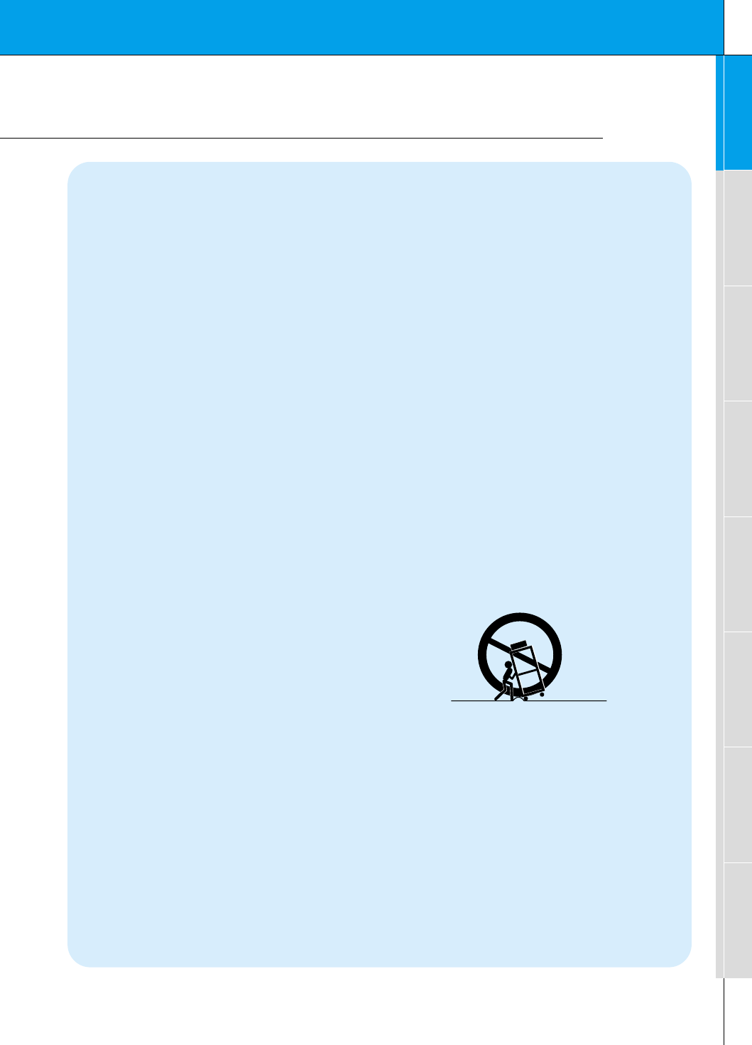
7. Accessories Carts and Stands
Do not place this product on a slippery or
tilted surface, or on an unstable cart, stand,
tripod, bracket, or table. The product may
slide or fall, causing serious injury to a child
or adult, and serious damage to the product.
Use only with a cart, stand, tripod, bracket,
or table recommended by the manufacturer,
or sold with the product. Any mounting of
the product should follow the manufacturer’s
instructions, and should use a mounting
accessory recommended by the manufac-
turer.
8. Transporting Product
A product and cart combination should be
moved with care. Quick stops, excessive
force, and uneven surfaces may cause the
product and cart combination to overturn.
9. Attachments
Do not use attachments not recommended
by the product manufacturer as they may
cause hazards.
10. Ventilation
Slots and openings in the cabinet are pro-
vided for ventilation and to ensure reliable
operation of the product and to protect it
from overheating, and these openings must
not be blocked or covered.
PORTABLE CART WARNING
(Continued on next page)
SAFETY INSTRUCTIONS
6
SAFETY INSTRUCTIONS
The openings should never be blocked by
placing the product on a bed, sofa, rug, or
other similar surface. This product should
not be placed in a built-in installation such
as a bookcase or rack unless proper ventila-
tion is provided or the manufacturer’s
instructions have been adhered to.
11. Power Sources
This product should be operated only from
the type of power source indicated on the
marking label. If you are not sure of the type
of power supply to your home, consult your
product dealer or local power company. For
products intended to operate from battery
power, or other sources, refer to the operat-
ing instructions.
12. Power-Cord Polarization
This product is equipped with a polarized
alternating-current line plug (a plug having
one blade wider than the other). This plug
will fit into the power outlet only one way.
This is a safety feature. If you are unable to
insert the plug fully into the outlet, try
reversing the plug. If the plug should still fail
to fit, contact your electrician to replace your
obsolete outlet. Do not defeat the safety
purpose of the polarized plug.
13. Power-Cord Protection
Power-supply cords should be routed so
that they are not likely to be walked on or
pinched by items placed upon or against
them, paying particular attention to cords at
plugs, convenience receptacles, and the
point where they exit from the product.
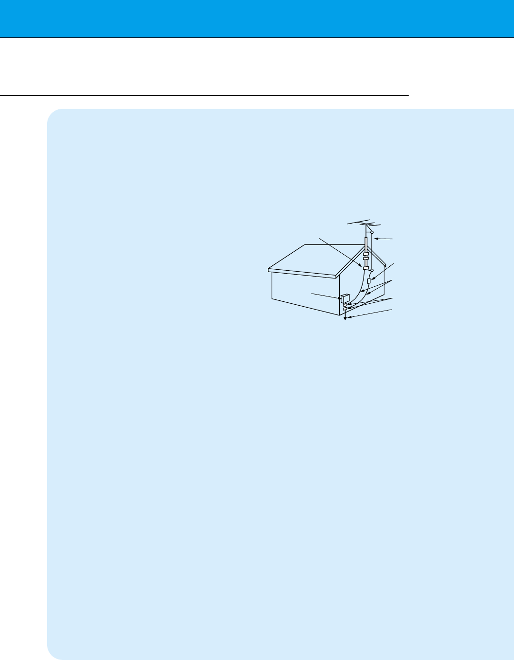
14. Outdoor Antenna Grounding
If an outside antenna or cable system is
connected to the product, be sure the
antenna or cable system is grounded so as
to provide some protection against voltage
surges and built-up static charges. Article
810 of the National Electrical Code (U.S.A.),
ANSI/ NFPA 70 provides information with
regard to proper grounding of the mast and
supporting structure, grounding of the lead-
in wire to an antenna discharge unit, size of
grounding conductors, location of antenna-
discharge unit, connection to grounding
electrodes, and requirements for the
grounding electrode.
15. Lightning
For added protection for this product
(receiver) during a lightning storm, or when
it is left unattended and unused for long
periods of time, unplug it from the wall outlet
and disconnect the antenna or cable sys-
tem. This will prevent damage to the product
due to lightning and power-line surges.
16. Power Lines
An outside antenna system should not be
located in the vicinity of overhead power
lines or other electric light or power circuits,
or where it can fall into such power lines or
circuits. When installing an outside antenna
system, extreme care should be taken to
keep from touching such power lines or cir-
cuits as contact with them might be fatal.
17. Overloading
Do not overload wall outlets and extension
cords as this can result in a risk of fire or
electric shock.
18. Object and Liquid Entry
Never push objects of any kind into this
(Continued from previous page)
Antenna Lead in Wire
Antenna Discharge Unit
(NEC Section 810-20)
Grounding Conductor
(NEC Section 810-21)
Ground Clamps
Power Service Grounding
Electrode System (NEC
Art 250, Part H)
Ground Clamp
Electric Service
Equipment
Example of Grounding According to National
Electrical Code Instructions
NEC - National Electrical Code

7
Safety instructions Monitor Overview Connections Basic operation Sleep timer Picture & Sound Special features Others
product through openings as they may
touch dangerous voltage points or short-out
parts that could result in a fire or electric
shock. Never spill liquid of any kind on the
product.
19. Servicing
Do not attempt to service this product your-
self as opening or removing covers may
expose you to dangerous voltage or other
hazards. Refer all servicing to qualified ser-
vice personnel.
20. Damage Requiring Service
Unplug this product from the wall outlet and
refer servicing to qualified service personnel
under the following conditions:
a. If the power-supply cord or plug is dam-
aged.
b. If liquid has been spilled, or objects have
fallen into the product.
c. If the product has been exposed to rain
or water.
d. If the product does not operate normally
by following the operating instructions.
Adjust only those controls that are cov-
ered by the operating instructions as an
improper adjustment of other controls
may result in damage and will often
require extensive work by a qualified
technician to restore the product to its
normal operation.
e. If the product has been dropped or the
cabinet has been damaged.
f. If the product exhibits a distinct change
in performance.
21. Replacement Parts
When replacement parts are required, be
sure the service technician has used
replacement parts specified by the manufac-
turer or have the same characteristics as
the original part. Unauthorized substitutions
may result in fire, electric shock, or other
hazards.
22. Safety Check
Upon completion of any service or repairs to
this product, ask the service technician to
perform safety checks to determine that the
product is in proper operating condition.
23. Wall or Ceiling Mounting
The product should be mounted to a wall or
ceiling only as recommended by the manu-
facturer. The product may slide or fall, caus-
ing serious injury to a child or adult, and
serious damage to the product.
24. Heat
The product should be situated away from
heat sources such as radiators, heat regis-
ters, stoves, or other products (including
amplifiers) that produce heat.
8
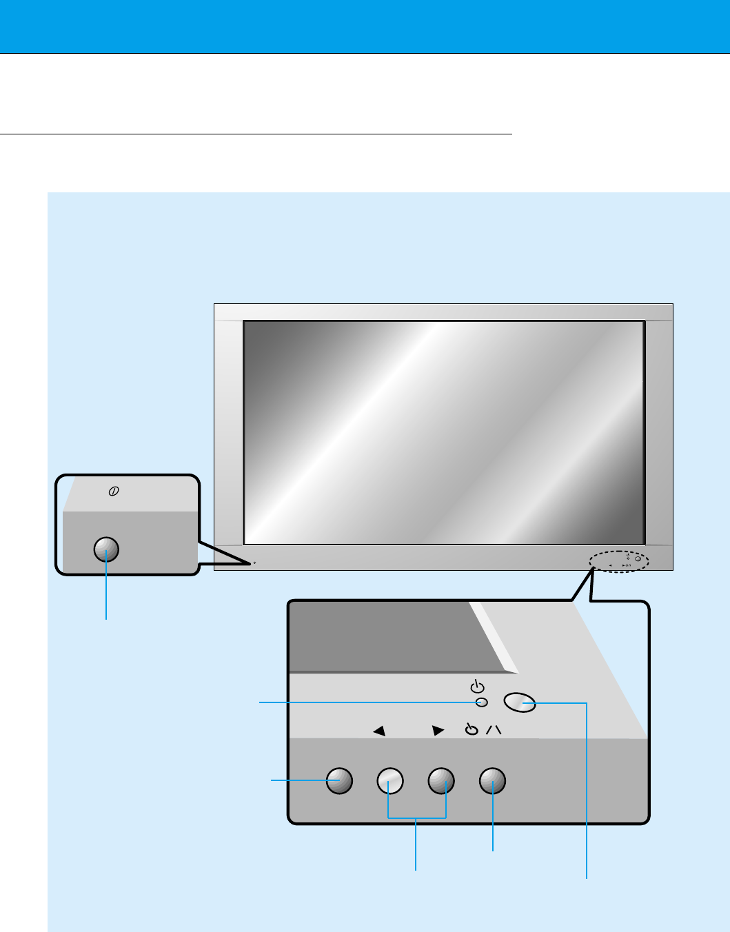
Front Panel Controls
ON/OFF
ON/OFF INPUT
SELECT VOLUME
INPUT
SELECT VOLUME
<Front Panel Controls>
Main power button
INPUT SELECT button
Power standby indicator
Illuminates red in standby
mode. Illuminates green
when the Monitor is turned
on.
Sub power button
VOLUME (FF,GG) buttons Remote control sensor
9
Safety instructions Monitor Overview Connections Basic operation Sleep timer Picture & Sound Special features Others
(+) ( ) (+)( )
AUDIO
(MONO)
RLVIDEO Y PBR
P
AV INPUT
AUDIO
RL RL
EXTERNAL SPEAKER (8Ω)AC INPUT
CONTROL
LOCK REMOTE
CONTROL
AUDIO INPUT RS-232CS-VIDEO COMPONENT RGB-PC INPUT
(VGA/SVGA/XGA/SXGA)
RGB-DTV INPUT
(480p/720p/1080i)
AUDIO
(MONO)
RL
AV INPUT S-VIDEO
COMPONENT
(480i/480p/720p/1080i)
(DVD/DTV INPUT)
RGB-PC INPUT
R
AUDIO INPUT
EXTERNAL SPEAKER(8Ω)
(+) ( ) (+)( )
RL
AC INPUT
REMOTE
CONTROL
CONTROL
LOCK
L
AUDIO
(VGA/SVGA/XGA/SXGA)
RGB-DTV INPUT
(480p/720p/1080i)
VIDEO YP
B
P
R
(DVD/DTV INPUT)
(480i/480p/720p/1080i)
RS-232C
ON/ OFF
ON/ OFF
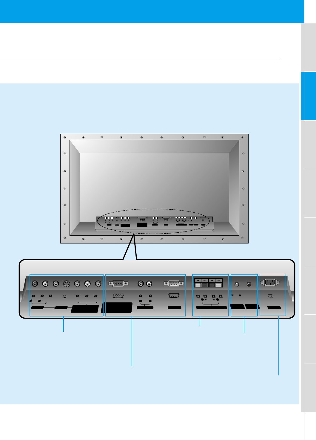
<Back Panel>
A/V INPUT /
COMPONENT (480i/480p/720p/1080i)
DVD/DTV INPUT jacks
EXTERNAL SPEAKER
(8 ohm output) CONTROL LOCK /
REMOTE CONTROL
When “CONTROL LOCK”
is set “ON”, wired remote
control mode is operated.
RGB-PC INPUT (VGA/SVGA/XGA/SXGA)
RGB-DTV INPUT (480p/720p/1080i) /
AUDIO INPUT /
RS-232C jacks
Connection Panel Overview
POWER INPUT SOCKET
This Monitor operates on an AC mains supply, the
voltage is as indicated as inside back cover of this
manual. Never apply DC power to the Monitor.
10
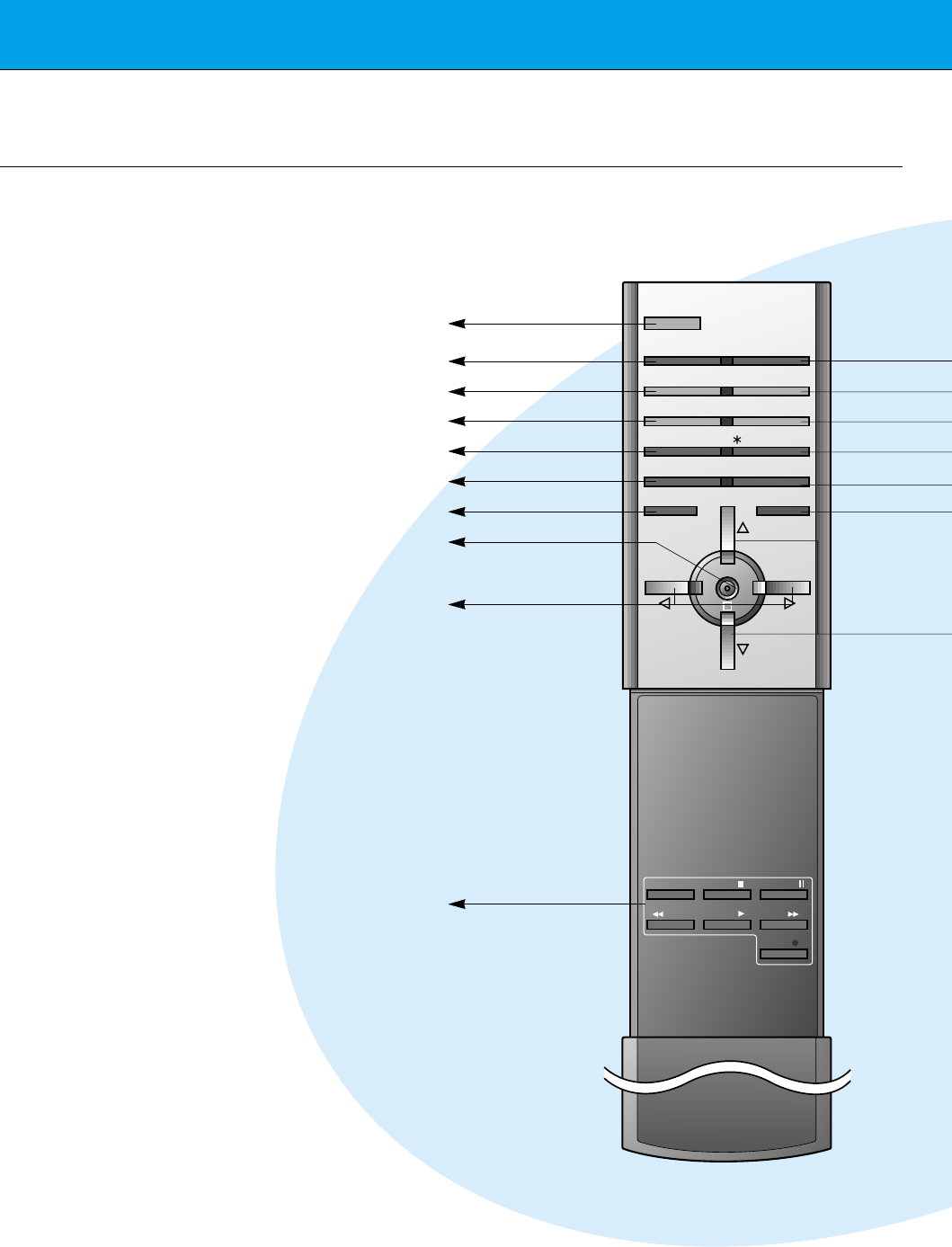
Remote Control Key Functions/Accessories
- When using the remote control aim it at the remote control sensor on the Monitor.
POWER
SLEEP INPUT SELECT
APC DASP
ARC STILL
PIP
PIP INPUT
MENU MUTE
OK
VOL
POWER STOP
PLAY FF
REC
REW
P/STILL
VOL
POSITION
/ TWIN PICTURE
POWER
SLEEP (Refer to p.35)
APC (Refer to p.36)
ARC (Refer to p.46)
PIP (Refer to p.26)
PIP INPUT (Refer to p.27, 30)
MENU
OK
VCR BUTTONS
controls a LG video cassette
recorder.
VOLUME (F, G)
11
Safety instructions Monitor Overview Connections Basic operation Sleep timer Picture & Sound Special features Others
AS mark
LG TV
1.5V
1.5V
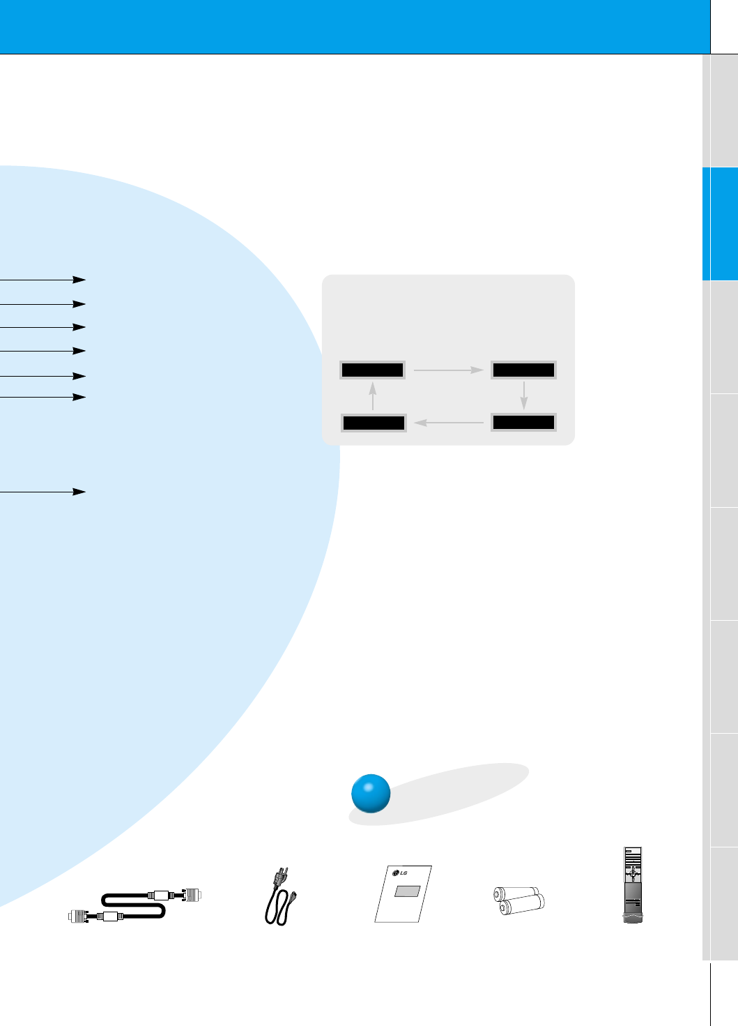
Accessories
D-sub 15 pin cable Power cord
POWER
SLEEP INPUT SELECT
APC DASP
ARC STILL
PIP
PIP INPUT
MENU MUTE
OK
VOL
POWER STOP
PLAY FF
REC
REW
P/STILL
VOL
POSITION
/ TWIN PICTURE
Remote control
Owner’s Manual Alkaline batteries
video/pc button on the remote control
Each press of this button changes the mode as
shown below.
S-VIDEO
COMPONENT
VIDEO
RGB
INPUT SELECT
DASP (Refer to p.40)
STILL (Refer to p.42)
POSITION (Refer to p.27)
D/ E
selects a menu item.
MUTE
switches the sound on or off.
TWIN PICTURE (Refer to p.29)
12
Monitor Installation
- It is recommended that this product only be used at an altitude of less than 6562 feet
(2000m) to get the best quality picture and sound.
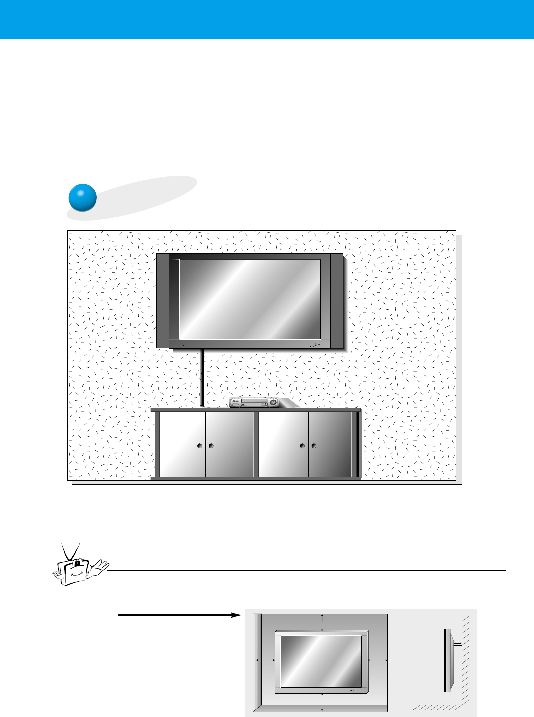
- Your monitor can be installed on a wall as shown below. Wall mount is optional, and is
not supplied with the monitor.
- This plasma display is designed to be mounted horizontally or vertically.
Wall Mount: Horizontal Installation
•The monitor can be installed on the wall as shown above.
(For further information, refer to the optional ‘Wall Mounting Bracket Installation
and Setup Guide’.)
•Speakers are optional, and shown for illustration only.
Tip
•Install this monitor only in a location where adequate ventilation is available.
4inch
4inch
4inch4inch
1.18inch
a. ( Wall mount minimum
allowable clearances
for adequate ventilation )
13
Safety instructions Monitor Overview Connections Basic operation Sleep timer Picture & Sound Special features Others
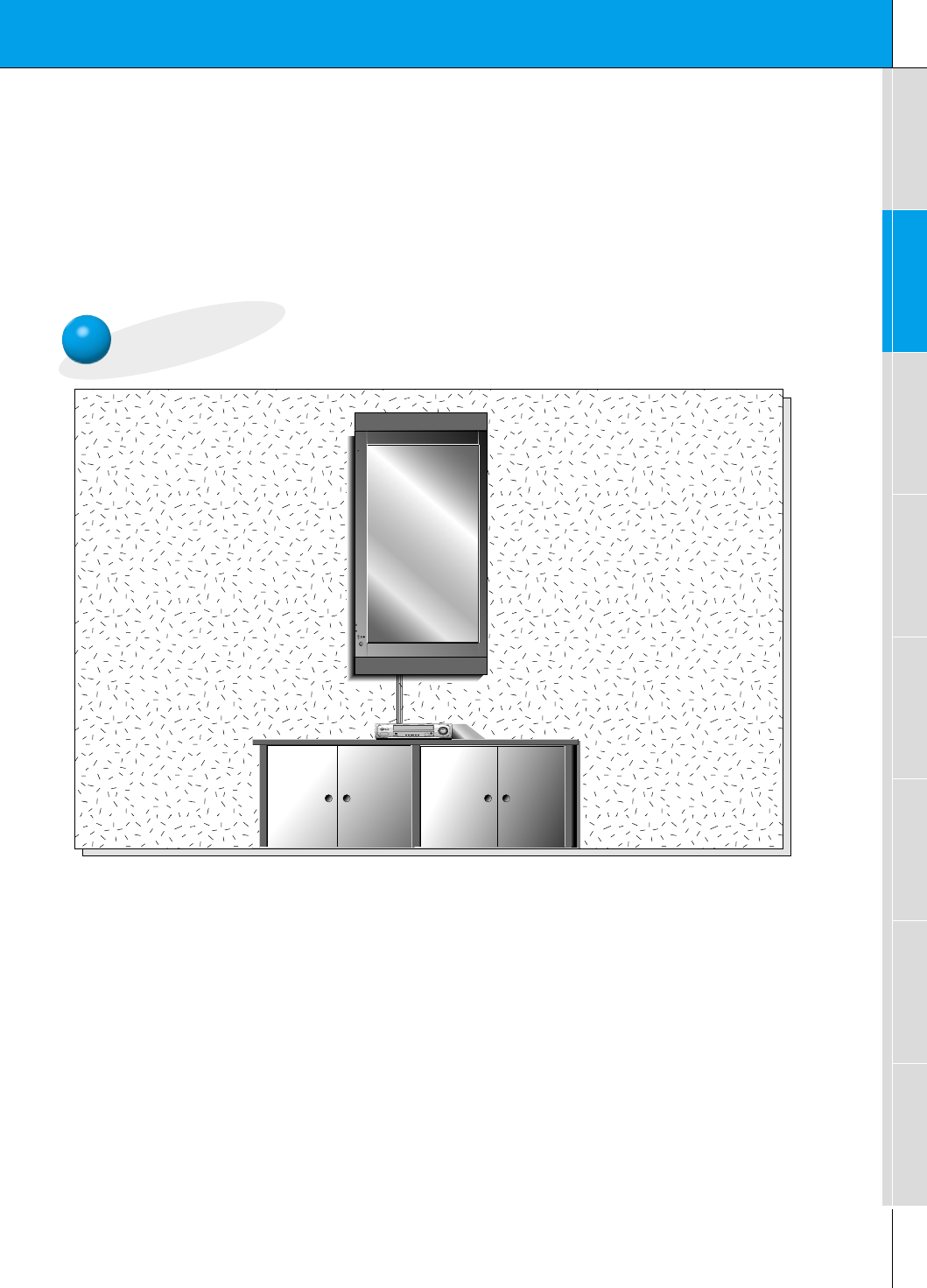
Wall Mount: Vertical Installation
•The monitor can be installed vertically on the wall as shown above.
Caution: When installing the monitor vertically, the front panel controls must be in the left-
down side position as shown above.
(For further information, refer to the optional ‘Wall Mounting Bracket Installation and Setup
Guide’.)
•Speakers are optional, and shown for illustration only.
•When installing the monitor vertically, you have to change the OSD display mode
so that the menus will appear correctly and also to protect the monitor from over-
heating (Refer to P. 33).
Caution
Caution
14
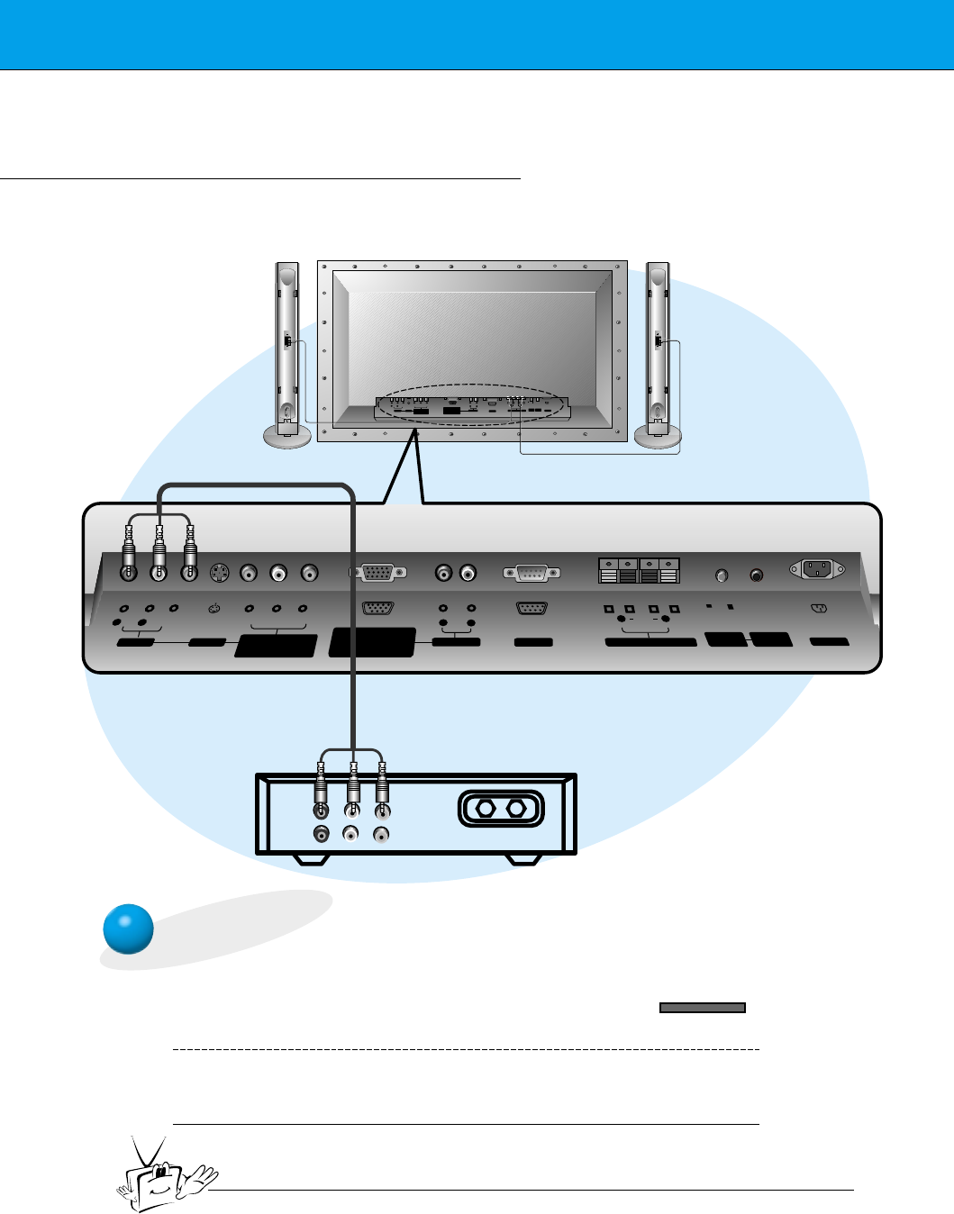
VCR Setup
Tips
•To avoid picture noise (interference), leave an adequate distance (20 inches or more)
between the VCR and monitor.
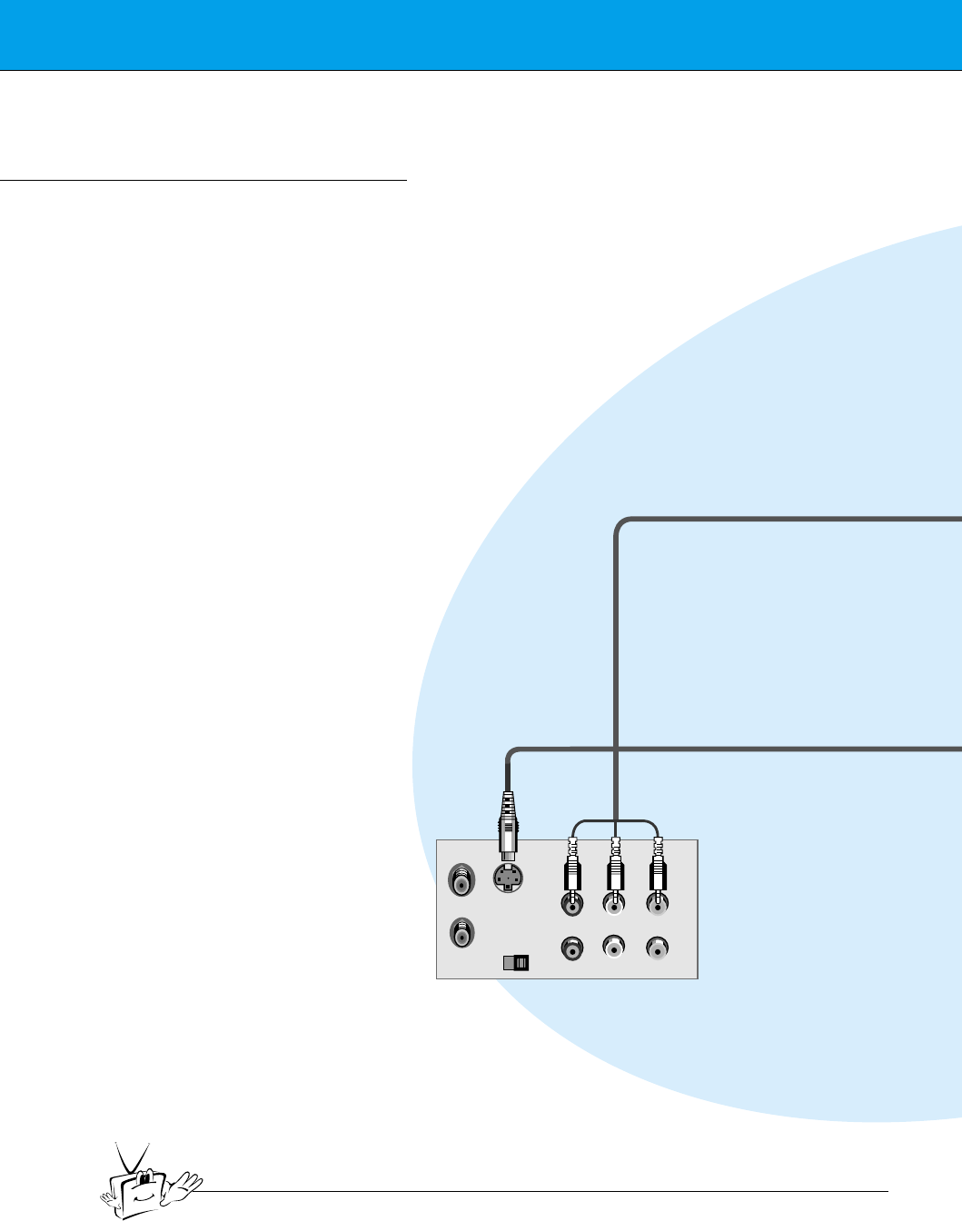
S-VIDEO OUT
IN
(R) AUDIO (L) VIDEO
< Back panel of VCR >
- As shown below, when connecting the Monitor to a VCR, match the colors of AV input
jacks on the Monitor with the output jacks on the VCR: Video = yellow, Audio (Left) =
white, Audio (Right) = red.
- If you have a mono VCR, connect the audio cable from the VCR to the AUDIO(L/MONO)
input of the Plasma Monitor.
- If you connect an S-VIDEO VCR to the S-VIDEO input, the picture quality is improved,
compared to connecting a regular VCR to the Video input.
- Avoid having a fixed image remain on the screen for a long period of time. A frozen still
picture from a VCR (or if a CH label is displayed) displayed on the screen for prolonged
periods will result in an image ghost remaining even when you change the image. Avoid
prolonged display of a still image.
15
Safety instructions Monitor Overview Connections Basic operation Sleep timer Picture & Sound Special features Others
(+) ( ) (+)( )
AUDIO
(MONO)
RLVIDEO Y P
BR
P
AV INPUT
AUDIO
RL RL
EXTERNAL SPEAKER (8Ω) AC INPUTAUDIO INPUT RS-232CS-VIDEO COMPONENT
(480i/480p/720p/1080i)
RGB-PC INPUT
(VGA/SVGA/XGA/SXGA)
RGB-DTV INPUT
(480p/720p/1080i)
(DVD/DTV INPUT)
(+) ( ) (+)( )
AUDIO
(MONO)
RL
AV INPUT S-VIDEO
COMPONENT
(480i/480p/720p/1080i)
(DVD/DTV INPUT)
RGB-PC INPUT
R
AUDIO INPUT
EXTERNAL SPEAKER(8Ω)
RL
AC INPUT
L
AUDIO
(VGA/SVGA/XGA/SXGA)
RGB-DTV INPUT
(480p/720p/1080i)
VIDEO YP
B
P
R
RS-232C
CONTROL
LOCK REMOTE
CONTROL
REMOTE
CONTROL
CONTROL
LOCK
ON/ OFF
ON/ OFF
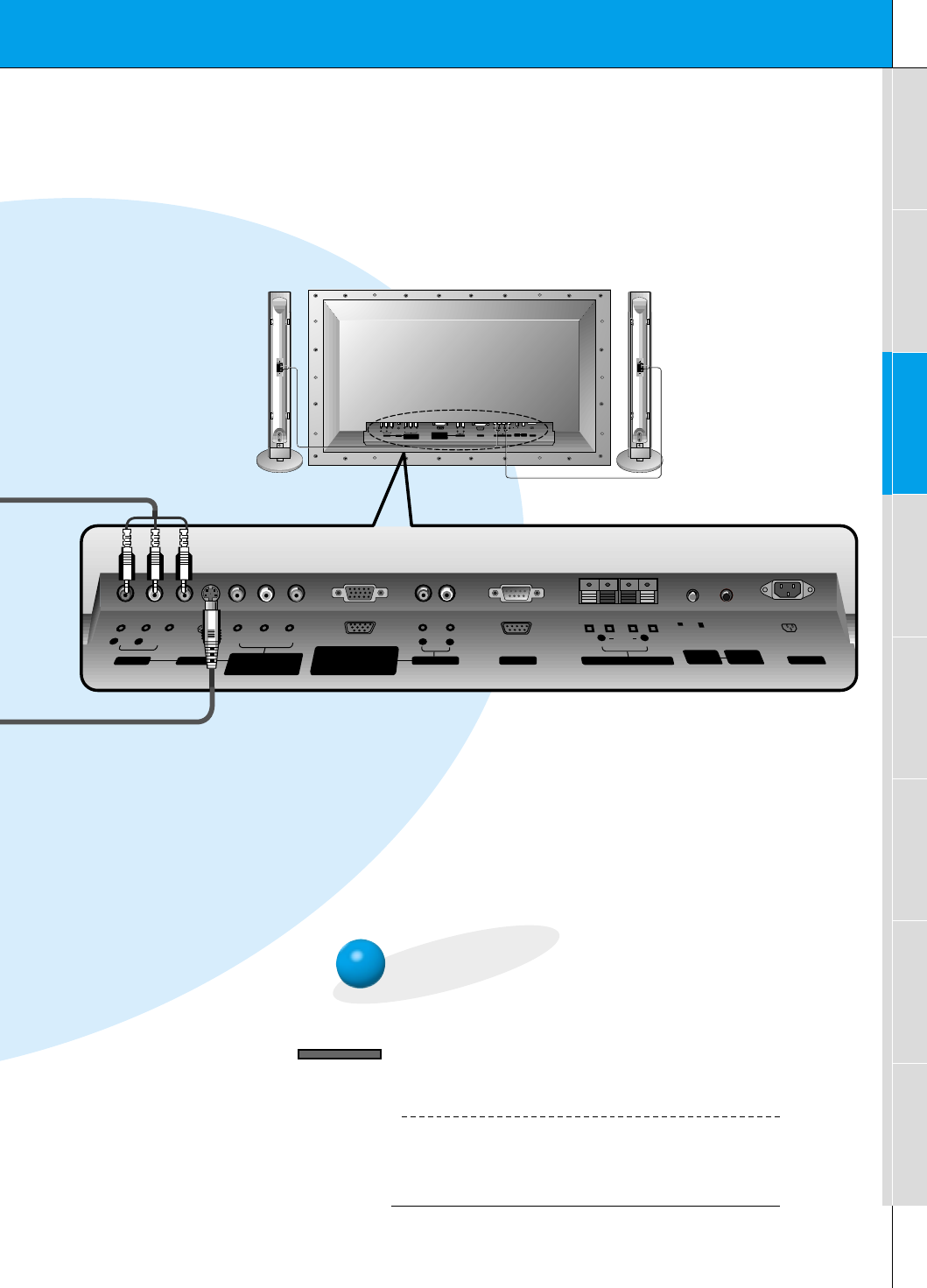
< Back panel of the Monitor >
To watch VCR
Press INPUT SELECT button on the
remote control and select VIDEO.
(When connecting with S-Video, select the
S-VIDEO.)
1
Insert a video tape into the VCR and press
the PLAY button on the VCR. See VCR
owner’s manual.
2
INPUT SELECT
16
Cable TV Setup
- After subscribing to a cable TV service from a local provider and installing a converter,
you can watch cable TV programming. This monitor cannot display TV programming
without a TV tuner or cable TV converter box.
TV
VCR RF Cable
(R) AUDIO (L) VIDEO
(+) ( ) (+)( )
AUDIO
(MONO)
RLVIDEO Y P
BR
P
AV INPUT
AUDIO
ON/ OFF
RL RL
EXTERNAL SPEAKER (8Ω) AC INPUTAUDIO INPUTS-VIDEO COMPONENT
(480i/480p/720p/1080i)
RGB-PC INPUT
(VGA/SVGA/XGA/SXGA)
RGB-DTV INPUT
(480p/720p/1080i)
(DVD/DTV INPUT)
(+) ( ) (+)( )
AUDIO
(MONO)
RL
AV INPUT S-VIDEO
COMPONENT
(480i/480p/720p/1080i)
(DVD/DTV INPUT)
RGB-PC INPUT
R
AUDIO INPUT
EXTERNAL SPEAKER(8Ω)
RL
AC INPUT
L
AUDIO
(VGA/SVGA/XGA/SXGA)
RGB-DTV INPUT
(480p/720p/1080i)
VIDEO YP
B
P
R
RS-232C
RS-232C
CONTROL
LOCK REMOTE
CONTROL
REMOTE
CONTROL
CONTROL
LOCK
ON/ OFF
To watch cable TV
Press INPUT SELECT button on the
remote control and select VIDEO source.
1
Tune to cable service provided channels
using the cable box.
2
Tips
•For further information regarding cable TV service, contact your local
cable TV service provider(s).
< Monitor back panel >
< Cable box >
Speakers shown
for illustration
only.
INPUT SELECT
17
Safety instructions Monitor Overview Connections Basic operation Sleep timer Picture & Sound Special features Others
RL
AUDIO VIDEO
(+) ( ) (+)( )
AUDIO
(MONO)
RLVIDEO Y PBR
P
AV INPUT
AUDIO
RL RL
EXTERNAL SPEAKER (8Ω) AC INPUTAUDIO INPUTS-VIDEO COMPONENT
(480i/480p/720p/1080i)
RGB-PC INPUT
(VGA/SVGA/XGA/SXGA)
RGB-DTV INPUT
(480p/720p/1080i)
(DVD/DTV INPUT)
(+) ( ) (+)( )
AUDIO
(MONO)
RL
AV INPUT S-VIDEO
COMPONENT
(480i/480p/720p/1080i)
(DVD/DTV INPUT)
RGB-PC INPUT
R
AUDIO INPUT
EXTERNAL SPEAKER(8Ω)
RL
AC INPUT
L
AUDIO
(VGA/SVGA/XGA/SXGA)
RGB-DTV INPUT
(480p/720p/1080i)
VIDEO YP
B
P
R
Camcorder
Video game set
DDR
RS-232C
RS-232C
CONTROL
LOCK REMOTE
CONTROL
REMOTE
CONTROL
CONTROL
LOCK
ON/ OFF
ON/ OFF
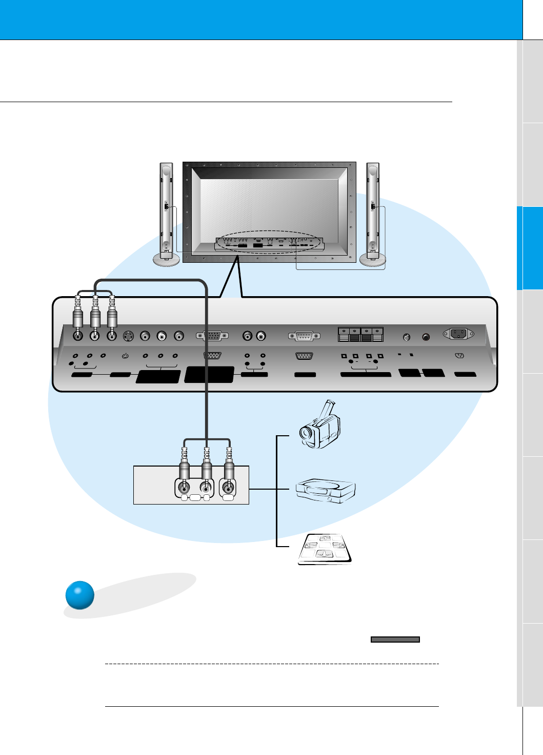
To watch external AV source
Press INPUT SELECT button on the
remote control of the monitor to select
VIDEO.
1
Operate the corresponding external equip-
ment. See external equipment operating
guide.
2
External AV Source Setup
- As shown below, when connecting the Monitor to an external source, match the colors of AV
input jacks on the Monitor with the output jacks on the audio/video equipment: Video = yel-
low, Audio (Left) = white, Audio (Right) = red.
<Back panel of the Monitor>
INPUT SELECT
18
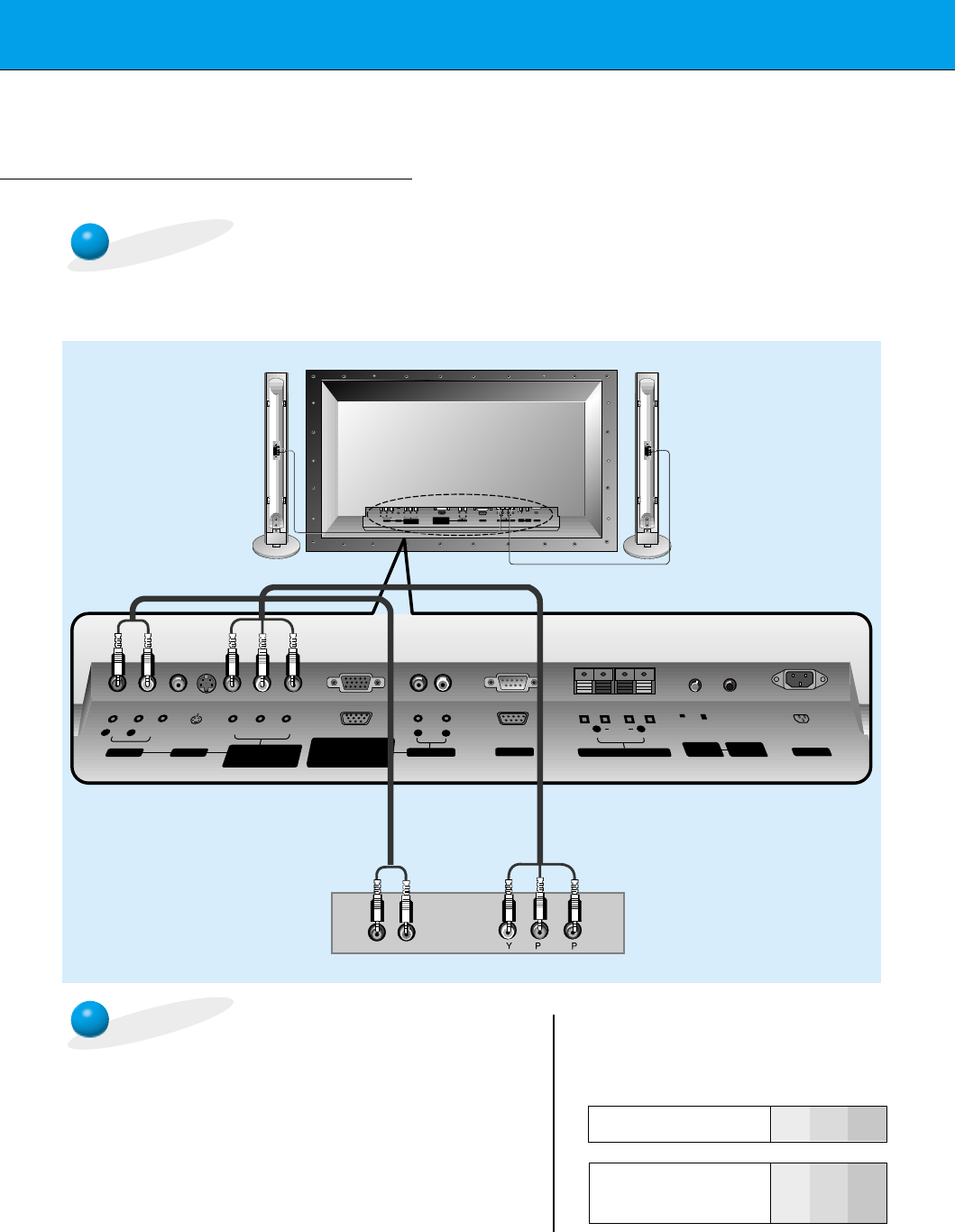
DVD Setup
•Connect DVD video inputs to Y, PB, PRof COMPONENT (480i/480p/720p/1080i)
(DVD/DTV INPUT) and audio inputs to Audio jacks of AV INPUT.
How to connect a DVD (digital video disk player)
How to use
•Turn on the DVD player, and insert a DVD.
•Press INPUT SELECT button on the remote control of the
monitor to select COMPONENT. Use the DVD player
according to its owner’s manual.
•Component Input ports
Connect DVD player jacks to Monitor
Component input jacks as indicated below.
(+) ( ) (+)( )
AUDIO
(MONO)
RLVIDEO Y P
BR
P
AV INPUT
AUDIO
RL RL
EXTERNAL SPEAKER (8Ω) AC INPUTAUDIO INPUTS-VIDEO COMPONENT
(480i/480p/720p/1080i)
RGB-PC INPUT
(VGA/SVGA/XGA/SXGA)
RGB-DTV INPUT
(480p/720p/1080i)
(DVD/DTV INPUT)
(+) ( ) (+)( )
AUDIO
(MONO)
RL
AV INPUT S-VIDEO
COMPONENT
(480i/480p/720p/1080i)
(DVD/DTV INPUT)
RGB-PC INPUT
R
AUDIO INPUT
EXTERNAL SPEAKER(8Ω)
RL
AC INPUT
L
AUDIO
(VGA/SVGA/XGA/SXGA)
RGB-DTV INPUT
(480p/720p/1080i)
VIDEO YP
B
P
R
BR
(R) AUDIO (L)
RS-232C
RS-232C
CONTROL
LOCK REMOTE
CONTROL
REMOTE
CONTROL
CONTROL
LOCK
ON/ OFF
ON/ OFF
< Back panel of a DVD player>
Component input jacks
on the Monitor YPBPR
Video output jacks
of DVD player
Y
Y
Y
Y
Pb
B-Y
Cb
PB
Pr
R-Y
Cr
PR
<Back panel of the Monitor>
19
Safety instructions Monitor Overview Connections Basic operation Sleep timer Picture & Sound Special features Others
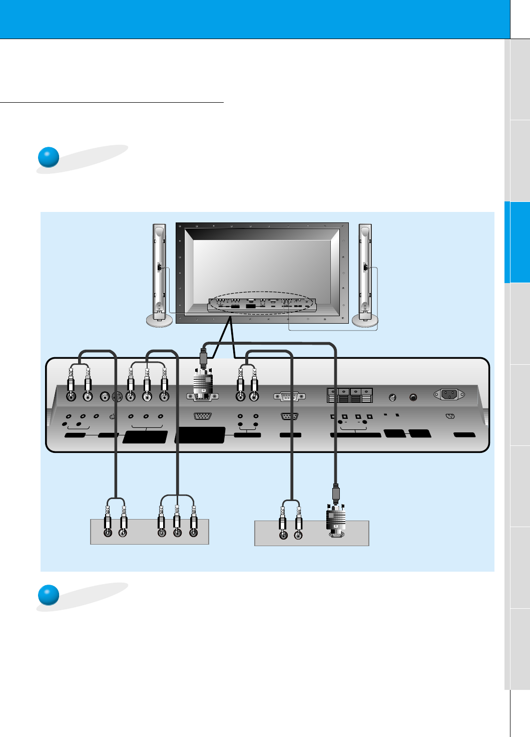
DTV Setup
- To watch digitally broadcast programs, purchase/connect a digital SET-TOP BOX.
- You can select only the 16:9 picture format in DTV 720p/1080i mode.
How to connect a user-supplied Digital Set-top Box
How to use
(R) AUDIO (L)
(R) AUDIO (L) Y P
BR
PDTV OUTPUT
(+) ( ) (+)( )
AUDIO
(MONO)
RLVIDEO Y P
BR
P
AV INPUT
AUDIO
RL RL
EXTERNAL SPEAKER (8Ω) AC INPUTAUDIO INPUTS-VIDEO COMPONENT
(480i/480p/720p/1080i)
RGB-PC INPUT
(VGA/SVGA/XGA/SXGA)
RGB-DTV INPUT
(480p/720p/1080i)
(DVD/DTV INPUT)
(+) ( ) (+)( )
AUDIO
(MONO)
RL
AV INPUT S-VIDEO
COMPONENT
(480i/480p/720p/1080i)
(DVD/DTV INPUT)
RGB-PC INPUT
R
AUDIO INPUT
EXTERNAL SPEAKER(8Ω)
RL
AC INPUT
L
AUDIO
(VGA/SVGA/XGA/SXGA)
RGB-DTV INPUT
(480p/720p/1080i)
VIDEO YP
B
P
R
RS-232C
RS-232C
CONTROL
LOCK REMOTE
CONTROL
REMOTE
CONTROL
CONTROL
LOCK
ON/ OFF
ON/ OFF
•Turn on the digital SET-TOP BOX.
(Refer to the owner’s manual for the digital SET-TOP BOX.)
•Press INPUT SELECT button on the remote control to select COMPONENT or RGB.
< Back panel of a digital SET-TOP BOX>
or
•You can use either the Monitor’s COMPONENT (Y, Pb, Pr) inputs or the single RGB-DTV
INPUT for video connections, depending on your Set Top Box connectors. Then, make the
corresponding Audio connections. See the diagram below for either set up.
<Back panel of the Monitor>
20
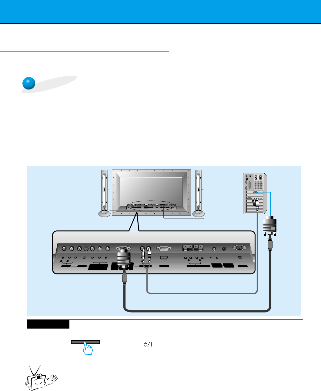
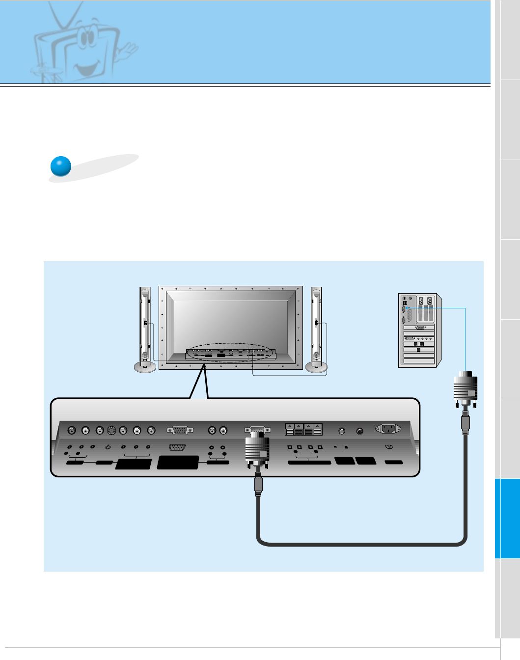
PC Setup
-You can easily connect the Plasma Display to your PC for outstanding image and sound.
-Use the Monitor to display images and sound from a PC Computer source.
On the remote control
How to use
(+) ( ) (+)( )
AUDIO
(MONO)
RLVIDEO Y PBR
P
AV INPUT
AUDIO
RL RL
EXTERNAL SPEAKER (8Ω) AC INPUTAUDIO INPUTS-VIDEO COMPONENT
(480i/480p/720p/1080i)
RGB-PC INPUT
(VGA/SVGA/XGA/SXGA)
RGB-DTV INPUT
(480p/720p/1080i)
(DVD/DTV INPUT)
(+) ( ) (+)( )
AUDIO
(MONO)
RL
AV INPUT S-VIDEO
COMPONENT
(480i/480p/720p/1080i)
(DVD/DTV INPUT)
RGB-PC INPUT
R
AUDIO INPUT
EXTERNAL SPEAKER
(8Ω)
RL
AC INPUT
L
AUDIO
(VGA/SVGA/XGA/SXGA)
RGB-DTV INPUT
(480p/720p/1080i)
VIDEO YP
B
P
R
RS-232C
RS-232C
CONTROL
LOCK REMOTE
CONTROL
REMOTE
CONTROL
CONTROL
LOCK
ON/ OFF
ON/ OFF
Tips
Back panel of the Monitor
INPUT SELECT
Setup Instructions to Connect a PC to your Monitor
• If the image output of the PC is set higher than
UXGA, no picture will appear on the Monitor.
(UXGA is not supported.)
• Connect the signal cable from the monitor Output
port on the PC to the RGB-PC INPUT
(VGA/SVGA/XGA/SXGA) port on the Monitor.
• Connect the audio cable from the PC to the Audio
ports of the Monitor. (Audio cables are not supplied
with the Monitor.)
• To set up the Monitor to operate within a PC win-
dows environment, select Normal, Standard or
Default monitor.
• The Monitor can not be used for Plug and Play
functionality.
• If your PC computer is equipped with a sound card,
adjust the sound output on the PC.
• It is recommended that the resolution output of the
PC should be set to 1280 x 720 to get the best
quality picture. (Look for a video card that uses the
nVIDIA GeForce 2 pro or similar chipset that
supports this resolution)
PC Setup
•First, turn on the PC computer and press the ON/OFF button on the
Monitor to apply power to it. Second, turn on the display by pressing
the button on the Monitor or by pressing the POWER button on
the Monitor’s remote control.
•Use the INPUT SELECT button on the remote control to select the
RGB input source.
•Set the resolution output of the PC to SXGA or under (1280 x 1024,
75Hz). (Refer to page 21.)
• Avoid keeping a fixed image on the Monitor's screen for a long period of time. The fixed image may
become permanently imprinted on the screen; use a screen saver when possible.
• If the resolution output of the PC computer is over SVGA, connect the PC to the RGB-PC
(VGA/SVGA/XGA/SXGA) input port on the Monitor. Change the PC computer resolution output
accordingly.
21
Safety instructions Monitor Overview Connections Basic operation Sleep timer Picture & Sound Special features Others
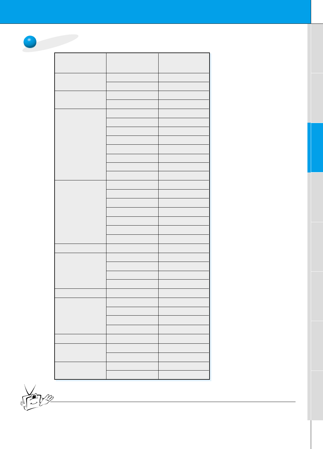
Monitor Image Display Specifications
640x350
720x400
31.468 70.09
37.861 85.08
31.469 70.08
37.927 85.03
31.469 59.94
35.000 66.66
37.861 72.80
37.500 75.00
43.269 85.00
45.913 90.03
53.011 100.04
64.062 120.00
35.156 56.25
37.879 60.31
48.077 72.18
46.875
832x624
1024x768
1280x720
1152x864
1152x870
1280x960
1280x1024
75.00
53.674 85.06
56.000 90.00
64.016 100.00
49.725 74.55
48.363 60.00
56.476 70.06
60.023 75.02
68.677 84.99
54.348 60.05
52.400 69.98
63.995 70.01
67.500 75.00
77.487 85.05
68.681 75.06
60.000 60.00
75.000 75.00
63.981 60.02
79.976 75.02
Resolution
Horizontal
Frequency (KHz) Vertical
Frequency (Hz)
640x480
800x600
Tips
•Synchronization input form : separate
22
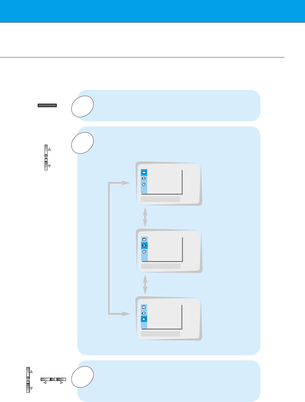
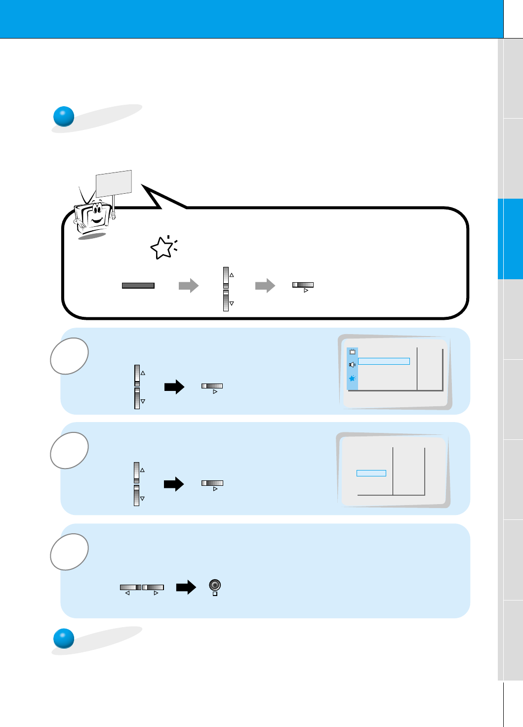
3
2
PC Mode Feature Check (Overview)
- Select RGB first, see page 11.
- Make sure the PC and monitor are both turned on.
- Use the monitor’s remote control to make adjustments.
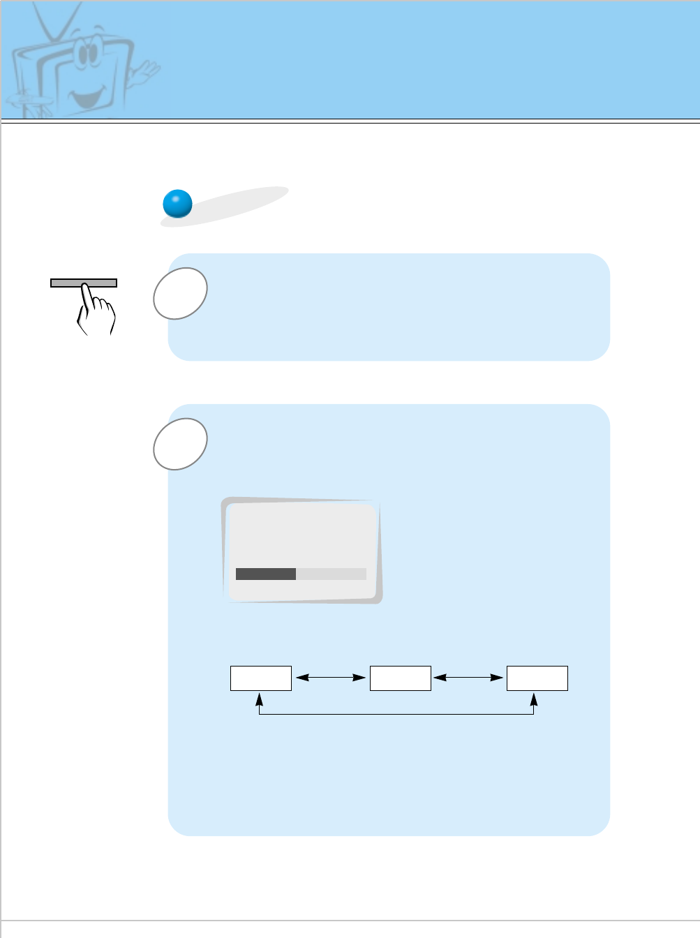
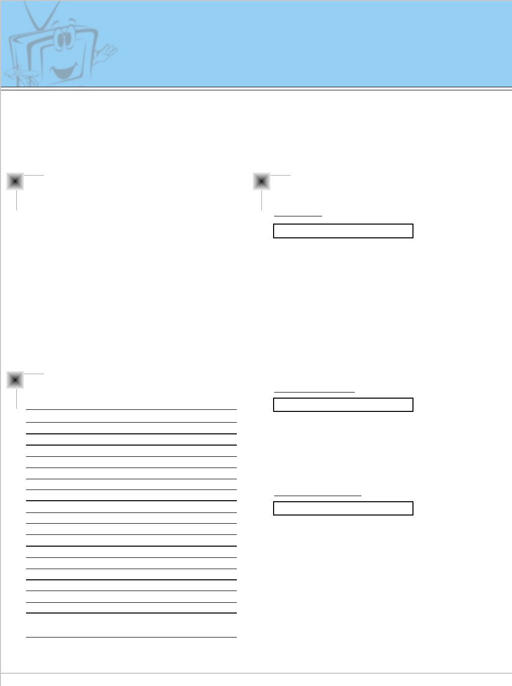
1Press the MENU button to show a menu on screen.
Press the Gbutton and then press the D / Eor F / G
buttons to select a feature you want to use.
•Press the OK button to exit menus.
Press the D / Ebutton to select a menu.
•Each press will cycle through the different menus as shown below.
APC G
DRP G
CONTRAST 85 G
BRIGHTNESS 50 G
COLOR 50 G
TINT 0 G
SHARPNESS 50 G
MOVE GNEXT AEXIT
D
E
DASP G
AVL G
TREBLE 50 G
BASS 50 G
BALANCE 0 G
MOVE GNEXT AEXIT
D
E
OSD ROTATE G
ARC G
SCREEN G
TRANSPARENCY G
PIP/DW G
SET ID G
COLOR TEMP. G
MOVE GNEXT AEXIT
D
E
<Picture menu>
<Sound menu>
<Special menu>
MENU
VOL VOL
23
Safety instructions Monitor Overview Basic operation Sleep timer Picture & Sound Special features Others
Connections
1
3
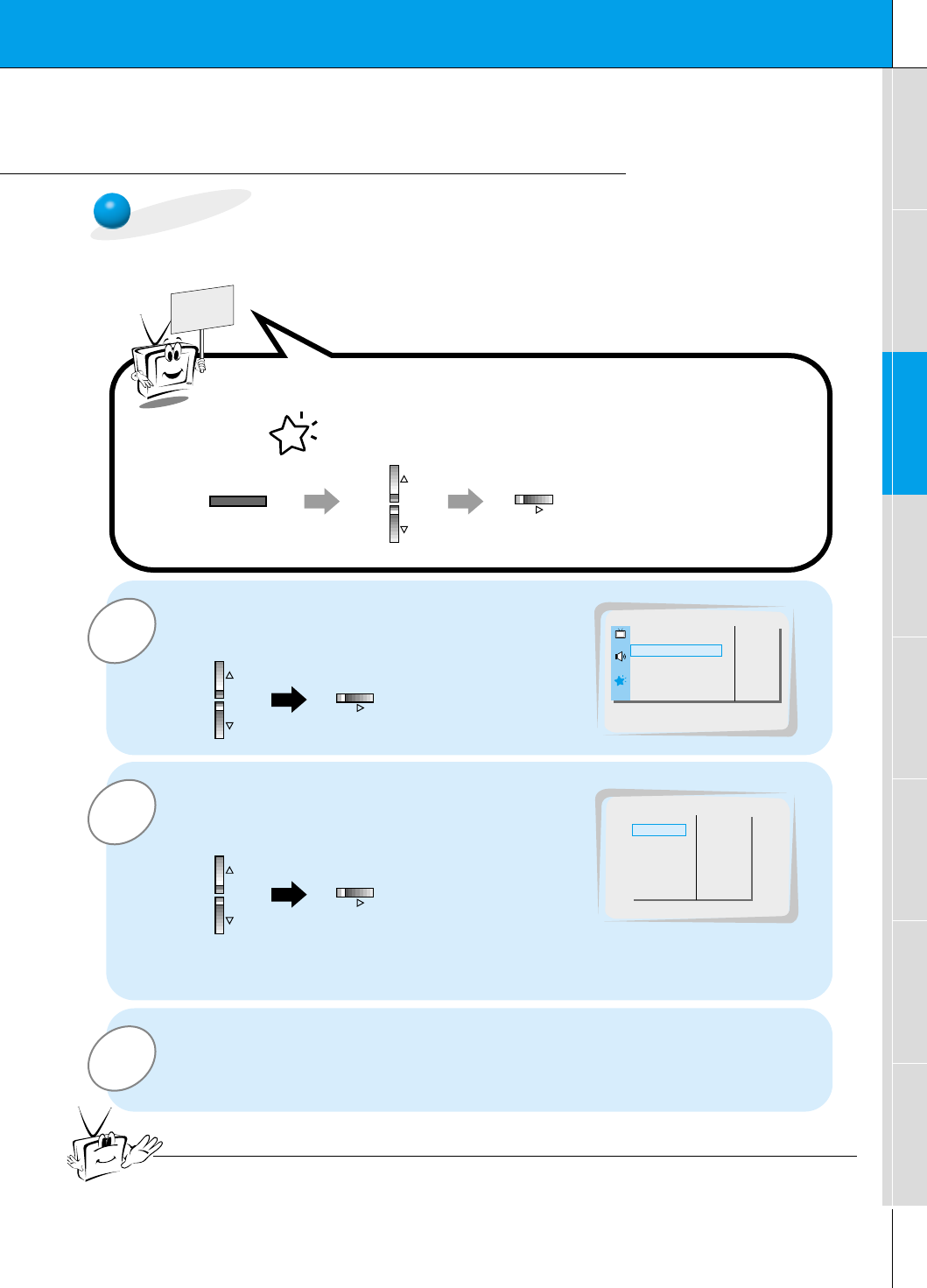
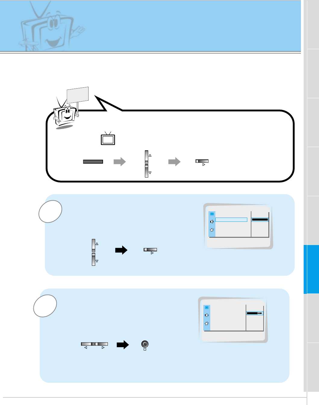
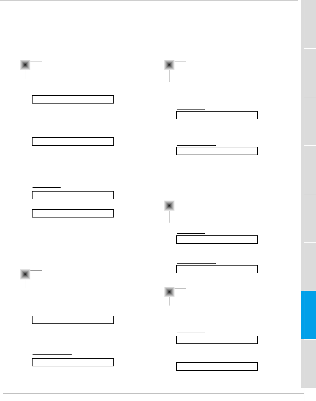
PC Mode Adjustments
Press the D / Ebutton to select SCREEN and
then press the Gbutton.
If picture needs to be adjusted more after Auto adjustment, you can
manually adjust the image position and PHASE.
- Automatically adjusts picture position and eliminates any image shaking.
Auto adjustment
READY
2Press the D / Ebutton to select
AUTO.CONFIG. and then press the G
button.
•When AUTO.CONFIG. has finished, "OK" will be shown on screen.
•If the position of the image is incorrect, try Auto adjustment again.
LANGUAGE
G
CAPTION
G
AUTO OFF
G
SCREEN
G
RGB-OUTPUT
G
AUTO.CONFIG.
G
V-POSITION
G
H-POSITION
G
PHASE
G
RESET
G
G
TO SET
AUTO.CONFIG.
OSD ROTATE G
ARC G
SCREEN G
TRANSPARENCY G
PIP/DW G
SET ID G
COLOR TEMP. G
G
TO SET
SCREEN
Tips
•If the image is still not correct, your Monitor is functioning properly but needs further
adjustment.
Press the MENU button and then press the D / Ebutton to
select menu. Press the Gbutton.
MENU
VOL
VOL
VOL
24
3
2
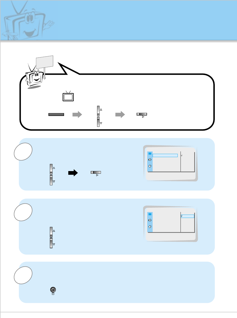
1Press the D / Ebutton to select SCREEN and
then press the Gbutton.
Adjusting horizontal / vertical position manually
READY
Press the D / Ebutton to select V-POSITION
or H-POSITION and then press the Gbutton.
•The adjustment range of V-POSITION is -50 ~ +50.
•The adjustment range of H-POSITION is -100 ~ +100.
•Based on the input mode, the adjustment range of V-POSITION/H-POSITION
may change.
•Based on the input signal, the position of the picture may not change even though
you have adjusted the horizontal or vertical position with this function.
Press the F / Gbuttons to adjust until you get desired horizontal or
vertical position and then press the OK button to remove menus.
Press the MENU button and then press the D / Ebutton to
select menu. Press the Gbutton.
LANGUAGE
G
CAPTION
G
AUTO OFF
G
SCREEN
G
RGB-OUTPUT
G
AUTO.CONFIG.
G
V-POSITION
G
H-POSITION
G
PHASE
G
RESET
G
0
V-POSITION
OSD ROTATE G
ARC G
SCREEN G
TRANSPARENCY G
PIP/DW G
SET ID G
COLOR TEMP. G
G
TO SET
SCREEN
- Only adjust V-POSITION and H-POSITION in DTV or component 480p/720p/1080i.
PC Mode Adjustments
MENU
VOL
VOL
VOL
VOL VOL
OK
25
Safety instructions Monitor Overview Basic operation Sleep timer Picture & Sound Special features Others
Connections
3
2
1Press the D / Ebutton to select SCREEN and
then press the Gbutton.
Picture Phase Adjustments
READY
•If the picture isn’t clear after auto adjustment and especially if the characters are still trembling, then
adjust the picture phase manually.
•When watching PIP/TWIN PICTURE, the SCREEN menu option is not available.
Initializing (Reset to factory value)
•To initialize the adjusted value, select RESET with the D/Ebutton and then
press the Gbutton.
Press the D / Ebutton to select PHASE and
then press the Gbutton.
•The adjustment range of PHASE is 0 ~ 63.
Press the F / Gbutton to adjust phase and then press the OK button.
LANGUAGE
G
CAPTION
G
AUTO OFF
G
SCREEN
G
RGB-OUTPUT
G
AUTO.CONFIG.
G
V-POSITION
G
H-POSITION
G
PHASE
G
RESET
G
30
PHASE
OSD ROTATE G
ARC G
SCREEN G
TRANSPARENCY G
PIP/DW G
SET ID G
COLOR TEMP. G
G
TO SET
SCREEN
MENU VOL
VOL
VOL
VOL VOL
OK
Press the MENU button and then press the D / Ebutton to
select menu. Press the Gbutton.
26
Picture In Picture (PIP) function
- PIP lets you view 2 different inputs (sources) on your monitor screen at the same time. One source will
be large, and the other source will show a smaller inset image.
- Select RGB input source before pressing PIP.
- This function works only in the following resolutions;
640x480, 800x600, 1024x768 (only in Vertical frequency 60 Hz)
- When you select RGB or DTV for main picture in PIP/Twin picture, you can watch video, cable TV or
DVD for sub picture.
- Color of main picture may be different from PIP’s in PIP/Twin picture mode.
- If input source for main picture is changed while in PIP/Twin picture mode, sub picture will disappear.
- When watching PIP/Twin picture, SCREEN option is not available in Special menu.
- With PIP active, not all picture formats can be used for the main/sub picture.
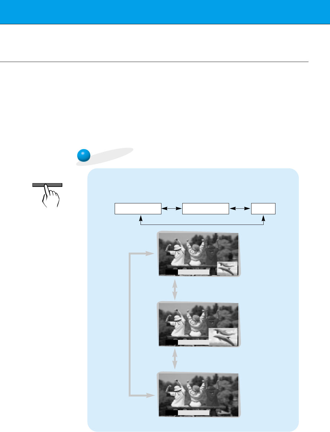
Watching the PIP (Picture in Picture)
Press the PIP button.
•Each time you press PIP or F /Gbutton, you can change the
PIP size as below.
PIP[S] PIP [L] OFF
PIP
F
PIP [S]
G
PIP
F
PIP [L]
G
PIP
F
OFF
G
<Small PIP>
<Large PIP>
<Off>
PIP
27
Safety instructions Monitor Overview Basic operation Sleep timer Picture & Sound Special features Others
Connections
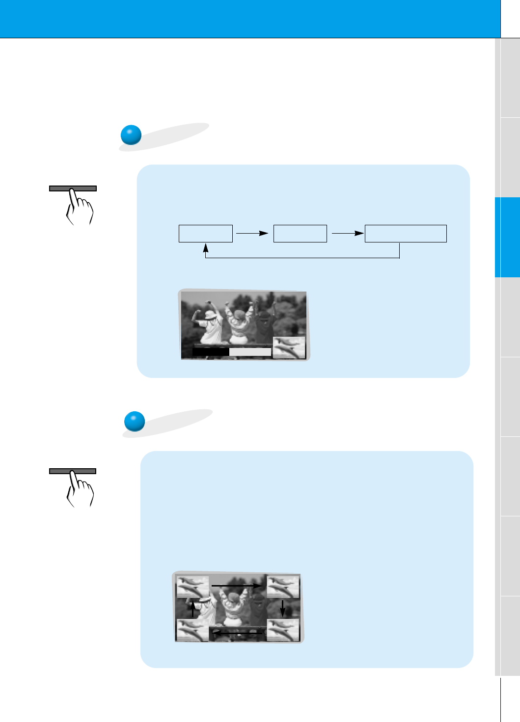
Selecting the source input signal
Press the PIP INPUT button in PIP mode.
•Each time you press PIP INPUT button, you toggle VIDEO,
S-VIDEO and COMPONENT.
COMPONENT source only works in 480i mode.
VIDEO S-VIDEO COMPONENT
PIP INPUT
F
VIDEO
G
Moving the Sub (inset) picture
Press the POSITION button in PIP mode.
•Each press of the POSITION button will change the position of
the sub picture on the screen as shown below.
PIP INPUT
POSITION
28
3
2
1Use the D / Ebuttons to select PIP/DW and
then press the Gbutton.
READY
Press the D / Ebutton to select SOUND
SELECT and then press the Gbutton.
•Each time you press D / E button, you toggle
between SOUND [M] or SOUND [S].
Press the D / Ebuttons to select main
image sound (SOUND [M]) or PIP (inset
image) sound (SOUND [S]) and then press
the OK button.
LANGUAGE
G
CAPTION
G
AUTO OFF
G
SCREEN
G
RGB-OUTPUT
G
DW
G
PIP
G
INPUT
G
SOUND SELECT
G
POSITION
G
SOUND [M]
SOUND [S]
SOUND SELECT
LANGUAGE
G
CAPTION
G
AUTO OFF
G
SCREEN
G
RGB-OUTPUT
G
DW
G
PIP
G
INPUT
G
SOUND SELECT
G
POSITION
G
SOUND [M]
SOUND [S]
OSD ROTATE G
ARC G
SCREEN G
TRANSPARENCY G
PIP/DW G
SET ID G
COLOR TEMP. G
G
TO SET
PIP/DW
- To select main or sub (inset) sound
- This function only works with the following resolutions;
640x480, 800x600, 1024x768 (only in Vertical frequency 60 Hz)
- To use this function, connect PC/DTV video output to RGB-PC INPUT/RGB-DTV INPUT and connect PC/DTV
audio outputs to AUDIO INPUT.
-SOUND SELECT is always the main picture sound (SOUND[M]) regardless of prior sound choice.
Selecting PIP sound options
SOUND [S]
Picture In Picture (PIP) function
MENU
VOL
VOL
VOL
OK
Press the MENU button and then press the D / Ebutton to
select menu. Press the Gbutton.
29
Safety instructions Monitor Overview Basic operation Sleep timer Picture & Sound Special features Others
Connections
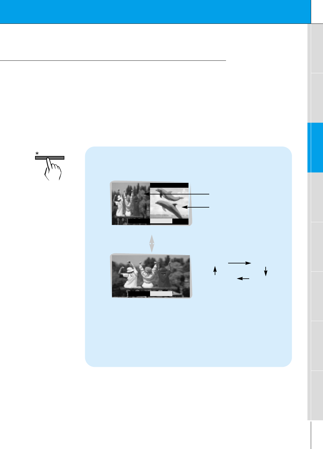
Twin picture mode
- As the name suggests, this mode splits the screen into 2, allowing 2 sources to be shown on
the monitor screen at the same time. Each source is given half the screen.
- Select RGB input source.
- This function works only in the following resolutions;
DTV 480p/720p/1080i, RGB 640x480 (only in Vertical frequency 60 Hz)
- With TWIN PICTURE active, not all picture formats can be used for the main/sub picture.
Press the ✱/TWIN PICTURE button.
•Each time you press ✱/TWIN PICTURE or F /Gbuttons, you
can select ON or OFF.
<ON>
<OFF>
DW
F
OFF
G
DW
F
ON
G
Sub picture
Main picture
•To avoid a permanent image
being burned into the screen,
the sub picture will move
every 2 hours.
:Center Upside
Downside Center
•The sub picture starts in the
center position and then
moves as described above.
•You may notice a small
amount of video noise at the
bottom or top of the sub pic-
ture. This is normal.
/ TWIN PICTURE
30
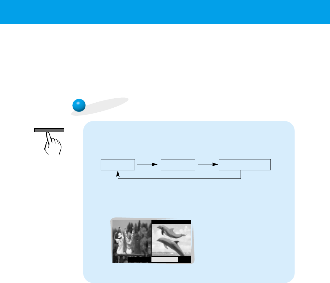
Twin picture mode
Selecting a source for the Twin picture
Press the PIP INPUT button in TWIN PICTURE mode.
•Each time you press PIP INPUT button, you toggle VIDEO,
S-VIDEO and COMPONENT.
COMPONENT source only works in 480i input signal.
PIP INPUT
F
VIDEO
G
VIDEO S-VIDEO COMPONENT
PIP INPUT
31
Safety instructions Monitor Overview Basic operation Sleep timer Picture & Sound Special features Others
Connections
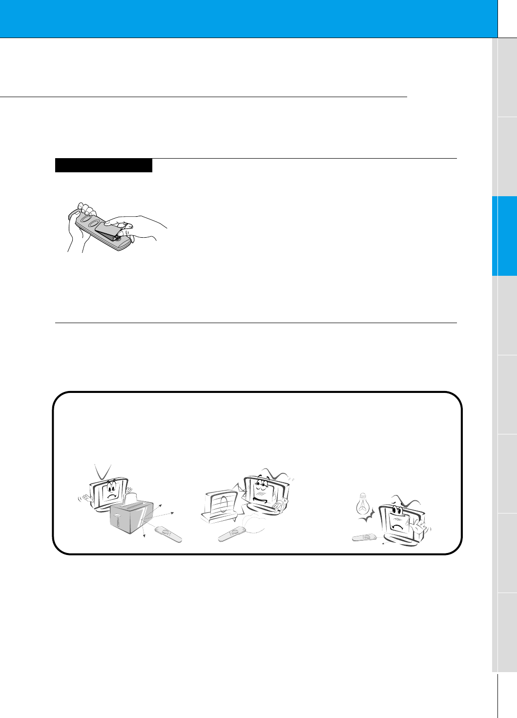
Using the remote control
Installing batteries
•Open the battery compartment cover on the back
of the remote control and insert the batteries with
correct polarity, match “+” with “+”, and match “-”
with “-”.
•Install two 1.5V “AAA” alkaline batteries.
Don’t mix used batteries with new batteries.
Notes for using the remote control
Make sure these are no
objects between the
remote control and its
sensor.
Don’t place the remote control
near a heater or damp place.
Strong impact on the remote con-
trol may cause operation failure.
Signal from the remote control
may be disturbed by sun light or
other strong light. In this case,
turn the set to other direction.
32
Turning on the Monitor
3
2
1
2
1
- When using the remote control, aim it at its sensor on the Monitor.
Turning on the Monitor just after installation
Turning on the Monitor (power cord is still connected)
Connect power cord correctly.
Press the main ON/OFF button on the Monitor. At this moment, the Monitor is
switched to standby mode. Press the or INPUT SELECT button on the
Monitor or press the POWER or INPUT SELECT button on the remote control
and then the Monitor will be turned on.
Press the or INPUT SELECT button on the Monitor or press the POWER
or INPUT SELECT button on the remote control and then the Monitor will be
turned on.
If the Monitor is turned off with the button on the Monitor
• Press the main ON/OFF button on the Monitor to turn on the Monitor.
If the Monitor is turned off with the ON/OFF button on the Monitor
• Press the main ON/OFF button on the Monitor and then press the or
INPUT SELECT button on the Monitor or press the POWER or INPUT
SELECT button on the remote control and then the Monitor will be turned on.
If the Monitor is turned off with the remote control and also the ON/OFF
button on the Monitor
Tips
•Adjusting volume level
The volume(GG) button increases the sound and the volume(FF) button reduces
the level of sound.
33
Safety instructions Monitor Overview Connections Basic operation Sleep timer Picture & Sound Special features Others
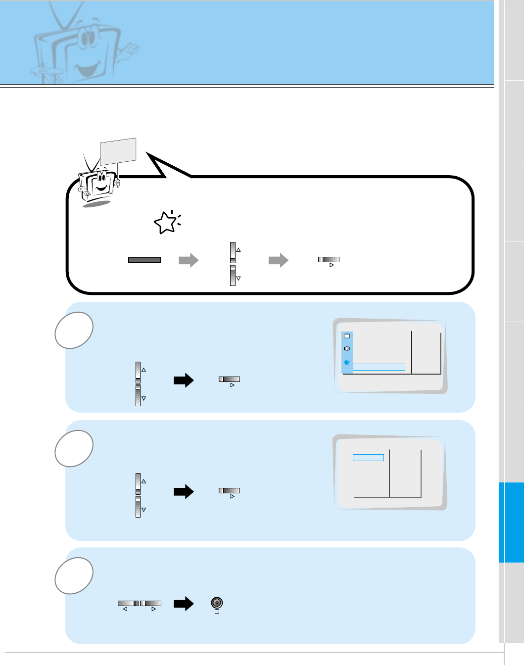
OSD Display Rotation
3
2
1
READY
Press the D / Ebutton to select OSD
ROTATE and then press the Gbutton.
Press the D / Ebutton to select
NORMAL or ROTATE.
•Select NORMAL when mounting the monitor horizontally.
•Select ROTATE when mounting the monitor vertically.
Press the OK button to exit.
OSD ROTATE G
ARC G
SCREEN G
TRANSPARENCY G
PIP/DW G
SET ID G
COLOR TEMP. G
NORMAL
ROTATE
OSD ROTATE
OSD ROTATE G
ARC G
SCREEN G
TRANSPARENCY G
PIP/DW G
SET ID G
COLOR TEMP. G
NORMAL
ROTATE
NORMAL
OK
MENU VOL
VOL
Press the MENU button and then press the D / Ebutton to
select menu. Press the Gbutton.
34
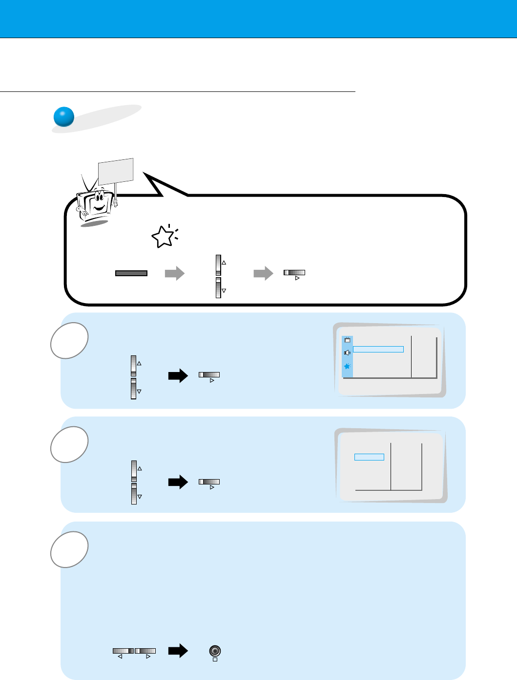
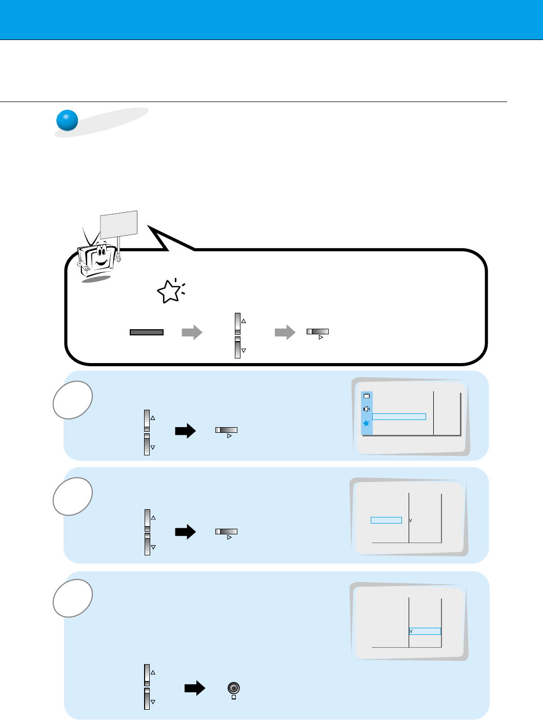
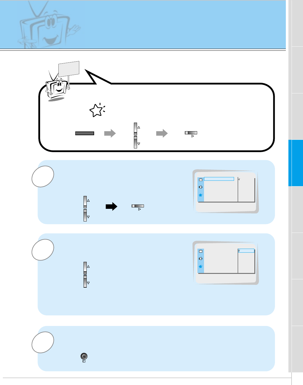
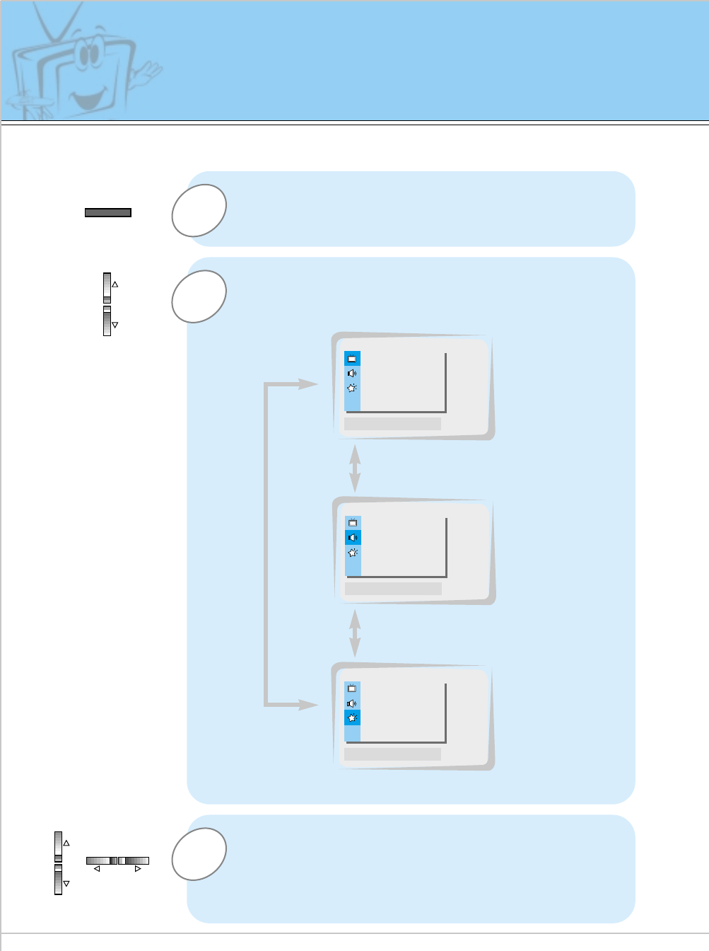
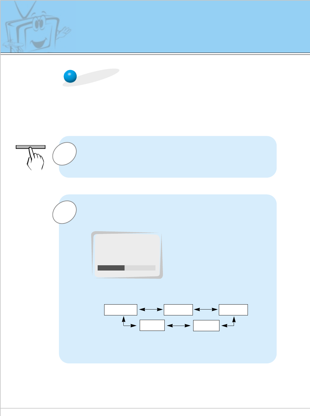
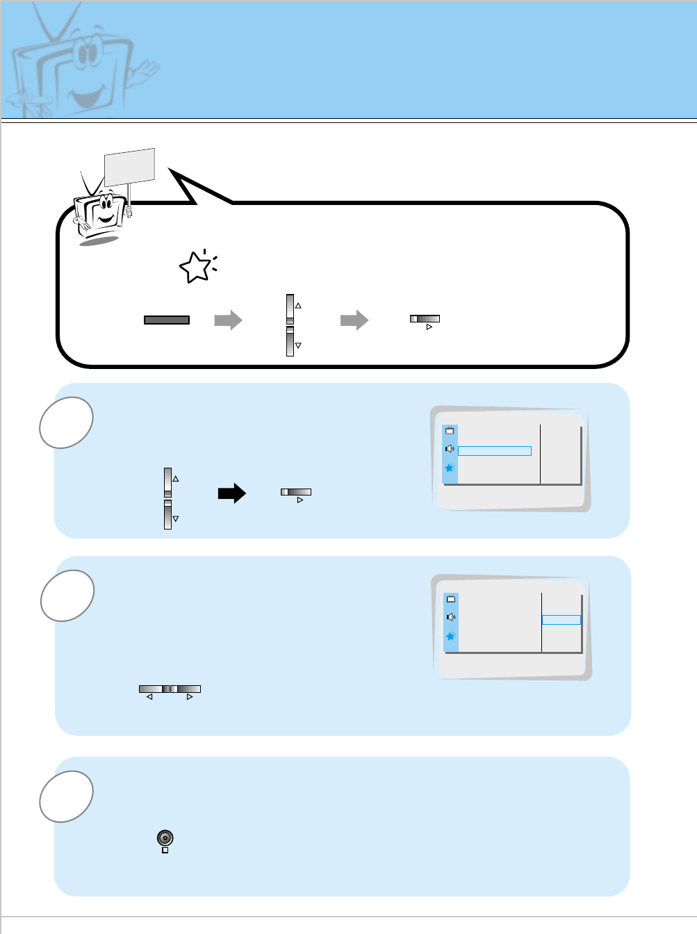
1
3
2
Press the MENU button.
Press the D / Ebutton.
•Each press will cycle through the menus shown below.
Checking features
Press the Gbutton to select a feature to adjust,
and then press the D / Eor F / Gbuttons to
adjust the selected item.
•Press the OK button to exit.
APC G
DRP G
CONTRAST 100 G
BRIGHTNESS 50 G
COLOR 50 G
TINT 0 G
SHARPNESS 50 G
MOVE GNEXT AEXIT
D
E
DASP G
AVL G
TREBLE 50 G
BASS 50 G
BALANCE 0 G
MOVE GNEXT AEXIT
D
E
OSD ROTATE G
ARC G
SCREEN G
TRANSPARENCY G
PIP/DW G
SET ID G
COLOR TEMP. G
MOVE GNEXT AEXIT
D
E
<Picture menu>
<Sound menu>
<Special menu>
- Use the remote control to make adjustments.
- Select VIDEO input source
MENU
VOL VOL
35
Safety instructions Monitor Overview Connections Basic operation Sleep timer Picture & Sound Special features Others
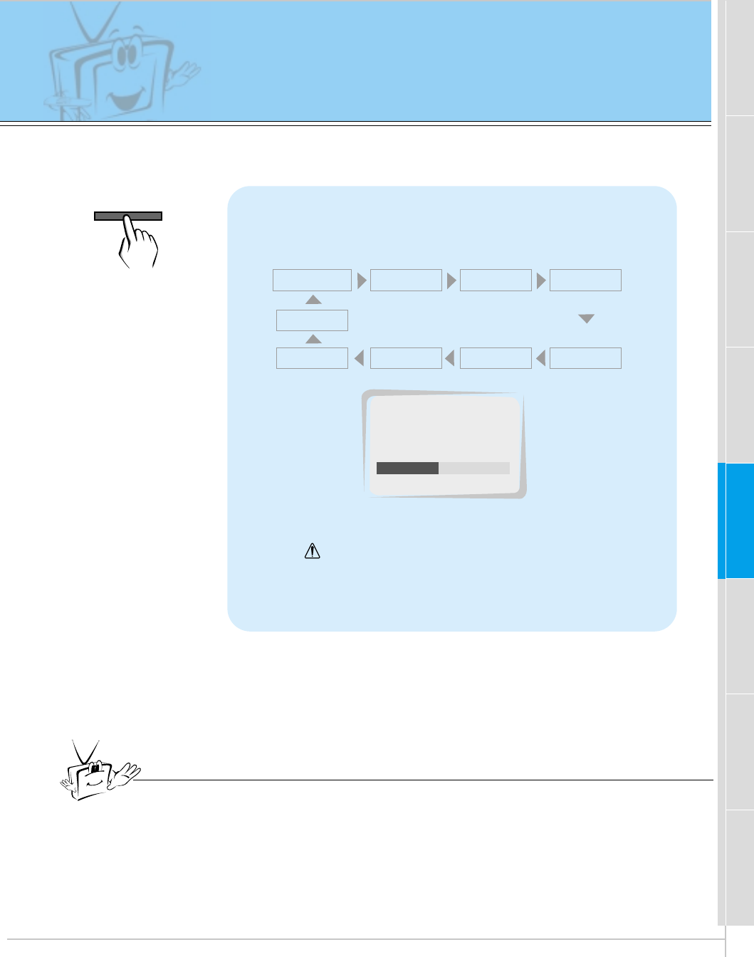
Setting Sleep Timer
Sleep Timer turns the Monitor off after a preset time
Press the SLEEP button to set sleep time.
Each time you press SLEEP button, the next pre-
set setting time is changed as follows:
•To release sleep time setting, press the SLEEP or
F /Gbutton repeatedly to select F--- G.
•‘ SLEEP 1’will be displayed one minute before
the Monitor is due to switch off.
F--- G F 10 GF20 G F 30 G
F120 GF 180 G
F240 G
F90 G F 60 G
Tips
•When the sleep time you want is displayed on the screen, don’t press the
SLEEP button. After 20 seconds, the screen display disappears and sleep
time is set.
•To check remaining sleep time after setting, press the SLEEP or OK button
just once.
•If you turn the Monitor off after setting the sleep timer, the setting is erased.
The sleep timer will then have to be set again.
F 30 G
SLEEP
SLEEP
36
2
1
APC (Auto Picture Control)
Press the APC button.
Press the APC or F / Gbuttons to select your
desired picture condition.
•Each press of F /Gbuttons changes the screen display as
shown below.
•You can also select CLEAR, SOFT or USER in the PIC-
TURE menu. User refers to adjustments you made to the
picture menu items. See next page.
CLEAR SOFT USER
F CLEAR G
APC
Auto picture control
Use APC to set the Monitor for the best picture appearance
- APC is not available in RGB or PIP/TWIN PICTURE modes.
APC
37
Safety instructions Monitor Overview Connections Basic operation Sleep timer Picture & Sound Special features Others
2
1
READY
Example : Changing the contrast.
Press the D / Ebutton to select CON-
TRAST and then press the
Gbutton.
•Adjust BRIGHTNESS, COLOR, TINT and
SHARPNESS in the same way.
Use the F / Gbuttons to make appro-
priate adjustments and then press the
OK button.
•Press the D /Ebuttons to select other items.
Adjusting picture appearance
APC G
DRP G
CONTRAST 100 G
BRIGHTNESS 50 G
COLOR 50 G
TINT 0 G
SHARPNESS 50 G
CONTRAST 100
APC G
DRP G
CONTRAST 70 G
BRIGHTNESS 50 G
COLOR 0 G
TINT 0 G
SHARPNESS 50 G
- PIP and Twin picture inset settings are not adjustable.
OK
VOL VOL
MENU VOL
VOL
Press the MENU button and then press the D / Ebutton to
select menu. Press the Gbutton.
38
DRP (Digital Reality Picture)
DRP improves image outlines in dark screens.
3
1
READY
Press the D / Ebutton to select DRP
and then press the Gbutton.
Press the OK button to exit.
APC G
DRP G
CONTRAST 100 G
BRIGHTNESS 50 G
COLOR 50 G
TINT 0 G
SHARPNESS 50 G
CLEAR
SOFT
DRP
2Press the D / Ebutton to select
CLEAR or SOFT.APC G
DRP G
CONTRAST 100 G
BRIGHTNESS 50 G
COLOR 50 G
TINT 0 G
SHARPNESS 50 G
CLEAR
SOFT
CLEAR
- This function works in video, component 480i mode.
MENU
VOL
OK
VOL
Press the MENU button and then press the D / Ebutton to
select menu. Press the Gbutton.
39
Safety instructions Monitor Overview Connections Basic operation Sleep timer Picture & Sound Special features Others
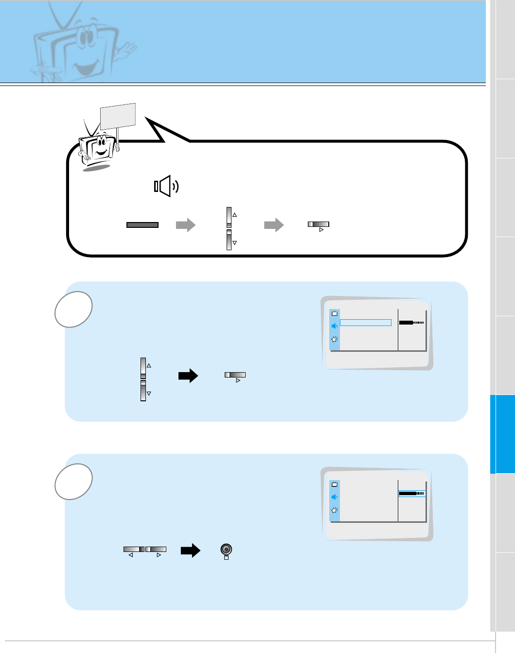
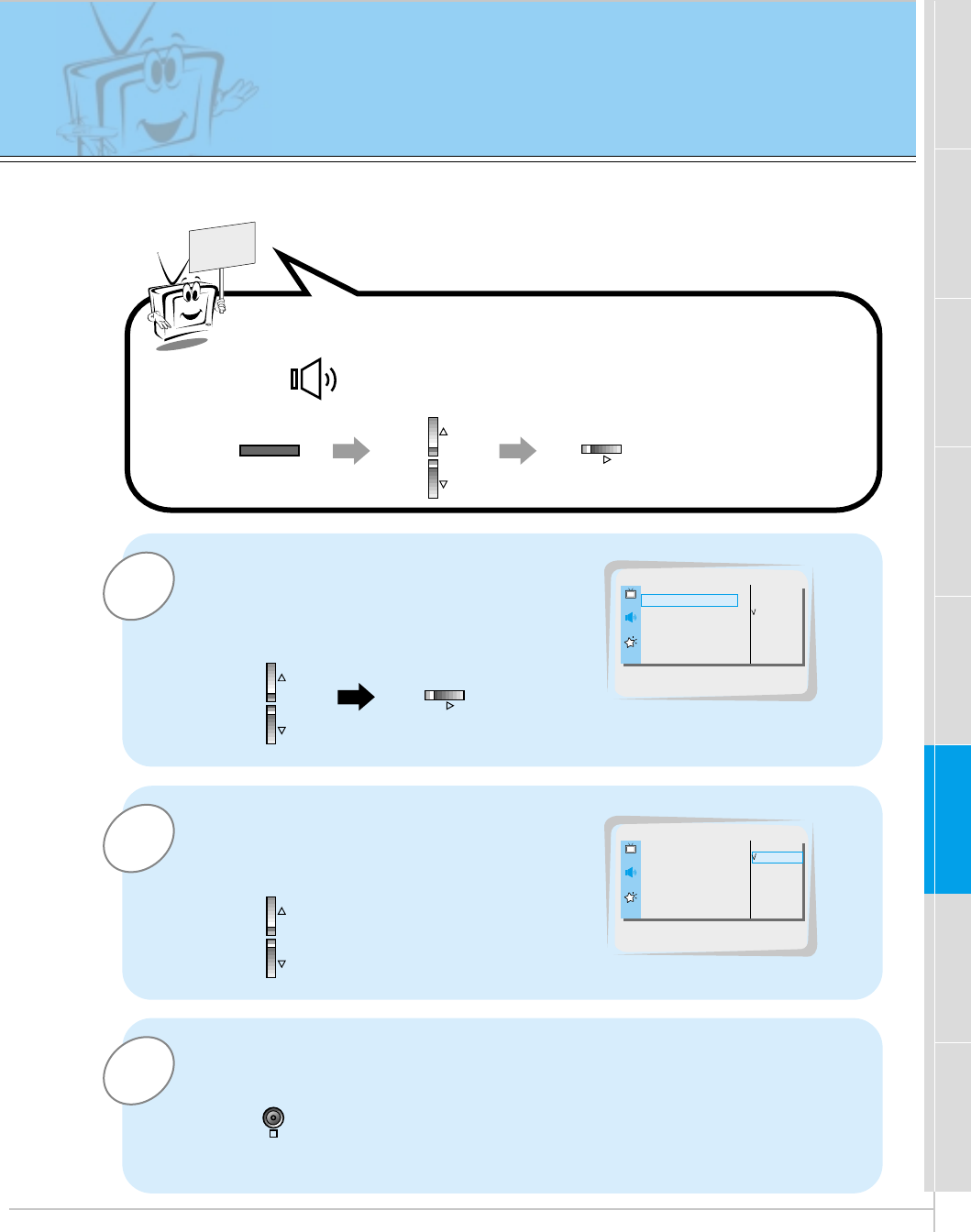
Adjusting sound
Manual setting
2
1
READY
Example : Adjustment treble
Use the D / Ebuttons to select
TREBLE and then press the
Gbutton.
•Adjust BASS and BALANCE in the same way.
Use the F / Gbuttons to make appropri-
ate adjustment and then press the OK
button to exit.
•Press the D /Ebuttons to select other options.
DASP G
AVL G
TREBLE 50 G
BASS 50 G
BALANCE 0 G
TREBLE 50
DASP G
AVL G
TREBLE 70 G
BASS 50 G
BALANCE 0 G
OK
VOL VOL
MENU VOL
VOL
Press the MENU button and then press the D / Ebutton to
select menu. Press the Gbutton.
40
Auto Sound Control
DASP (Digital Auto Sound Processing)
•This function lets you enjoy the best sound without any manual adjustment
because the Monitor automatically selects the appropriate audio tone levels
based on the program content.
1Press the DASP button.
2Press the DASP or F / Gbuttons to select a sound
setup.
•Each press of DASP or F /Gbuttons changes the screen
display as shown below.
•You can also select FLAT, SPORTS, CINEMA, MUSIC or
USER in the SOUND menu.
FLAT SPORTS
USER
CINEMA
MUSIC
F USER G
DASP
DASP
41
Safety instructions Monitor Overview Connections Basic operation Sleep timer Special features Others
Picture & Sound
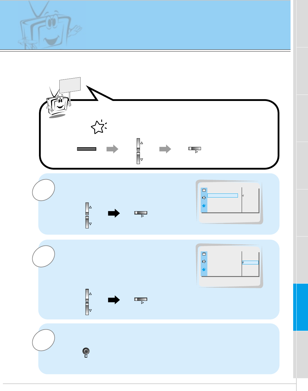
AVL (Auto Volume Leveler)
This feature maintains an equal volume level; even if you change channels.
3
1
READY
Press the D / Ebutton to select AV L
and then press the Gbutton.
Press the OK button to exit.
DASP G
AVL G
TREBLE 50 G
BASS 50 G
BALANCE 0 G
ON
OFF
AVL
2Press the D / Ebutton to select ON or
OFF.
ON
OFF
ON
DASP G
AVL G
TREBLE 50 G
BASS 50 G
BALANCE 0 G
OK
MENU VOL
VOL
Press the MENU button and then press the D / Ebutton to
select menu. Press the Gbutton.
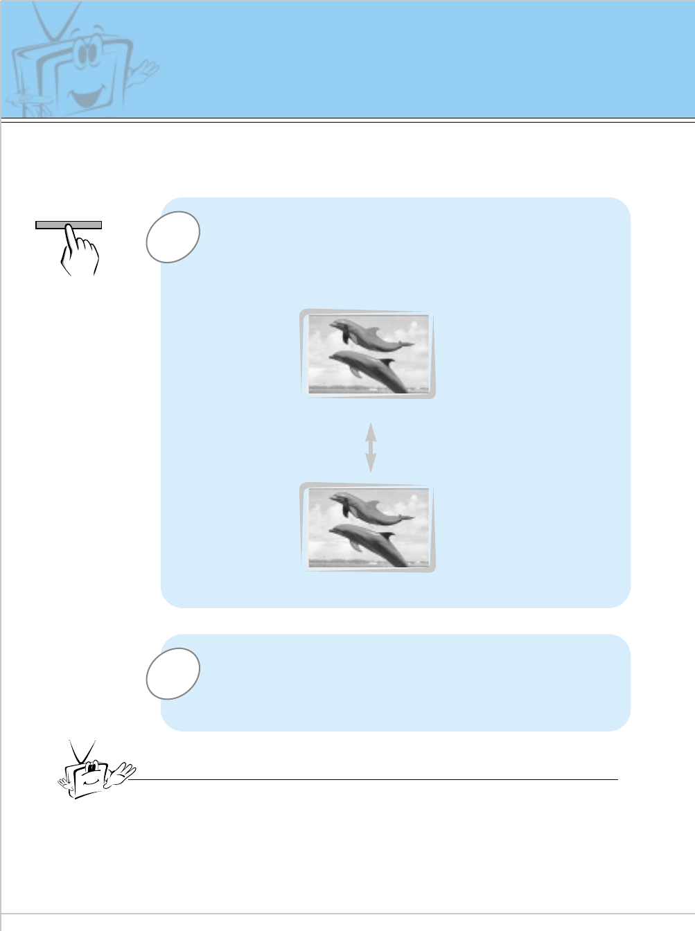
42
Using Still function
1
2
Press the STILL button.
•The image displayed is frozen(still).
•The sub picture is stilled in PIP or Twin picture mode.
•In PIP or TWIN PICTURE modes, the sub (inset) picture is
frozen.
<Moving image>
<Still image>
To return to normal viewing, press the STILL button
again.
Tips
•If still picture is on the screen for more than 5 minutes, the image becomes
dark.
If another function is activated, normal brightness of the screen is restored.
•This is a protective feature designed to reduce a ghost image burning into the
monitor.
•This feature does not work with RGB source.
- This feature isn’t available for RGB input source.
- Use with A/V or COMPONENT video inputs.
STILL
43
Safety instructions Monitor Overview Connections Basic operation Sleep timer Picture & Sound Special features Others
3
2
1
READY
Use the D / Ebutton to select SCREEN
and then press the Gbutton.
Use the D / Ebuttons to select TV or VCR.
•Select the VCR option if watching a VCR.
•Select the TV option for other
equipment.(Except VCR)
•Each time you press the D / Ebutton you toggle
between TV and VCR.
Press the OK button to exit.
OSD ROTATE G
ARC G
SCREEN G
TRANSPARENCY G
PIP/DW G
SET ID G
COLOR TEMP. G
TV
VCR
SCREEN
OSD ROTATE G
ARC G
SCREEN G
TRANSPARENCY G
PIP/DW G
SET ID G
COLOR TEMP. G
TV
VCR
VCR
Using the screen options
- This function works only in the video mode.
-
Use this option if there are a trembling or instability of a video tape on screen during viewing
the video.
OK
MENU
VOL
VOL
VOL
Press the MENU button and then press the D / Ebutton to
select menu. Press the Gbutton.
44
Adjusting OSD Transparency
To make the menus clear or opaque
3
2
1
READY
Press the D / Ebutton to select
TRANSPARENCY and then press the
Gbutton.
Press the F / Gbuttons to adjust OSD
transparency.
•The adjustment range of TRANSPARENCY
is 0 ~ 5.
Press the OK button to exit.
OSD ROTATE G
ARC G
SCREEN G
TRANSPARENCY G
PIP/DW G
SET ID G
COLOR TEMP. G
5
TRANSPARENCY
OSD ROTATE G
ARC G
SCREEN G
TRANSPARENCY G
PIP/DW G
SET ID G
COLOR TEMP. G
3
OK
MENU VOL
VOL
VOL VOL
Press the MENU button and then press the D / Ebutton to
select menu. Press the Gbutton.
45
Safety instructions Monitor Overview Connections Basic operation Sleep timer Picture & Sound Special features Others
READY
MENU VOL
Adjusting color temperature
3
2
1Press the D / Ebutton to select
COLOR TEMP. and then press the G
button.
Press the D / Ebutton to select RED and
then press the Gbutton.
(to adjust RED setting)
Use the F / Gbutton to make appropriate adjustments and then
press the OK button.
•The adjustment range of RED, GREEN and BLUE is -5 ~ +5.
•Adjust GREEN and BLUE in the same way.
OK
VOL
VOL
VOL VOL
OSD ROTATE G
ARC G
SCREEN G
TRANSPARENCY G
PIP/DW G
SET ID G
COLOR TEMP. G G TO SET
COLOR TEMP.
G
CAPTION
G
AUTO OFF
G
SCREEN
G
RGB-OUTPUT
G
RED
G
GREEN
G
BLUE
G
0
RED
- Adjustments also affect the color temperature of other input sources. Readjust color tem-
perature for PC input (RGB) if necessary.
- To initialize adjusted value, select ‘0’ in RED, GREEN and BLUE.
Press the MENU button and then press the D / Ebutton to
select menu. Press the Gbutton.
46
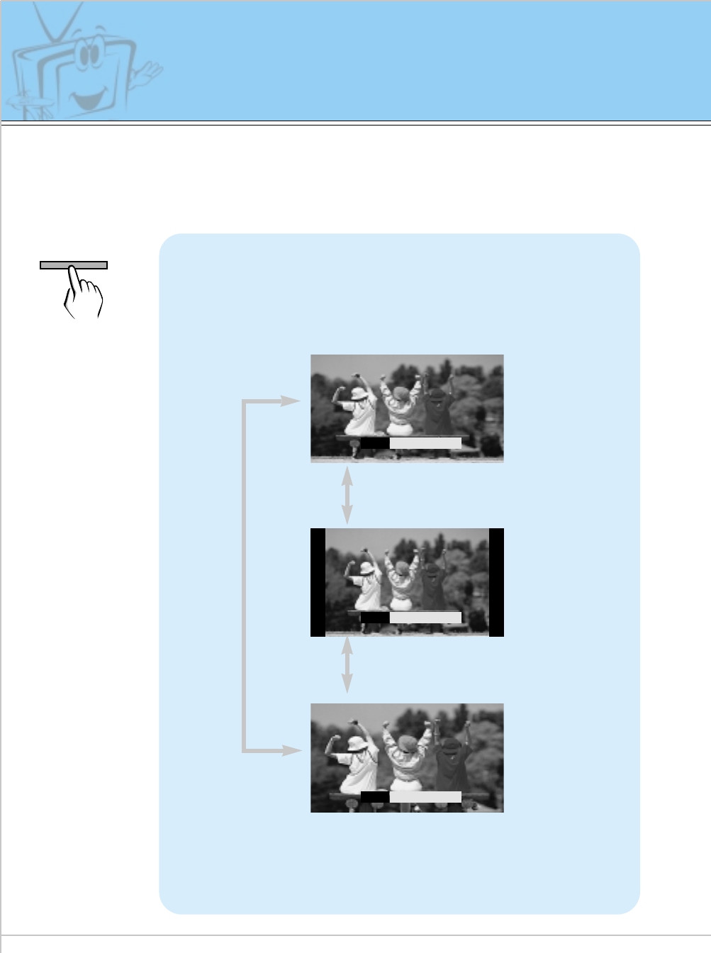
Setting picture format
Press the ARC button to select a desired picture
format.
•You can also select 16:9, 4:3 or ZOOM in the SPECIAL menu.
•Each time you press ARC or F /Gbuttons, you can
select 16:9, 4:3 or ZOOM alternatively.
ARC
F
16 : 9
G
<16:9>
<4:3>
<Zoom>
ARC
F
4 : 3
G
ARC
F
ZOOM
G
- With the RGB-PC input, you can select either 16:9 or 4:3 screen aspect ratios.
- With the RGB-DTV (720p, 1080i) input, you can select only 16:9 screen aspect ratios.
- If 4:3 mode is used for a long time, the outline of the image may remain on the screen after
you change to the 16:9 screen.
- Don’t display 4:3 picture format or TWIN PICTURE for more than 10 hours continuously.
ARC
47
Safety instructions Monitor Overview Connections Basic operation Sleep timer Picture & Sound Special features Others
-Connect the RS-232C input jack to an external control device (such as a computer or an A/V control
system) and control the Monitor’s functions externally.
-When you connect a control (RS-232C) cable to this monitor, use control cable attached the ferrite
core. If you do not do this, this monitor will not conform to mandatory CISPR22 (EN55022) standards.
(+) ( ) (+)( )
AUDIO
(MONO)
RLVIDEO Y PBR
P
AV INPUT
AUDIO
RL RL
EXTERNAL SPEAKER (8Ω) AC INPUT
CONTROL
LOCK REMOTE
CONTROL
AUDIO INPUTS-VIDEO COMPONENT
(480i/480p/720p/1080i)
RGB-PC INPUT
(VGA/SVGA/XGA/SXGA)
RGB-DTV INPUT
(480p/720p/1080i)
(DVD/DTV INPUT)
(+) ( ) (+)( )
AUDIO
(MONO)
RL
AV INPUT S-VIDEO
COMPONENT
(480i/480p/720p/1080i)
(DVD/DTV INPUT)
RGB-PC INPUT
AUDIO INPUT
EXTERNAL SPEAKER
(8Ω)
RL
AC INPUT
(VGA/SVGA/XGA/SXGA)
RGB-DTV INPUT
(480p/720p/1080i)
VIDEO YP
B
P
R
RS-232C
RS-232C
RL
AUDIO
REMOTE
CONTROL
CONTROL
LOCK
ON/ OFF
ON/ OFF
Monitor Rear Connections Panel
•Connect the serial port of the control device to the RS-232C jack on the Monitor back panel.
•RS-232C connection cables are not supplied with the Monitor.
•The Monitor remote control and front panel controls (except main power) will not be function-
al if the Monitor is controlled by a PC computer or other external device.
How to connect external control equipment
External Control Device Setup
48
External Control Device Setup
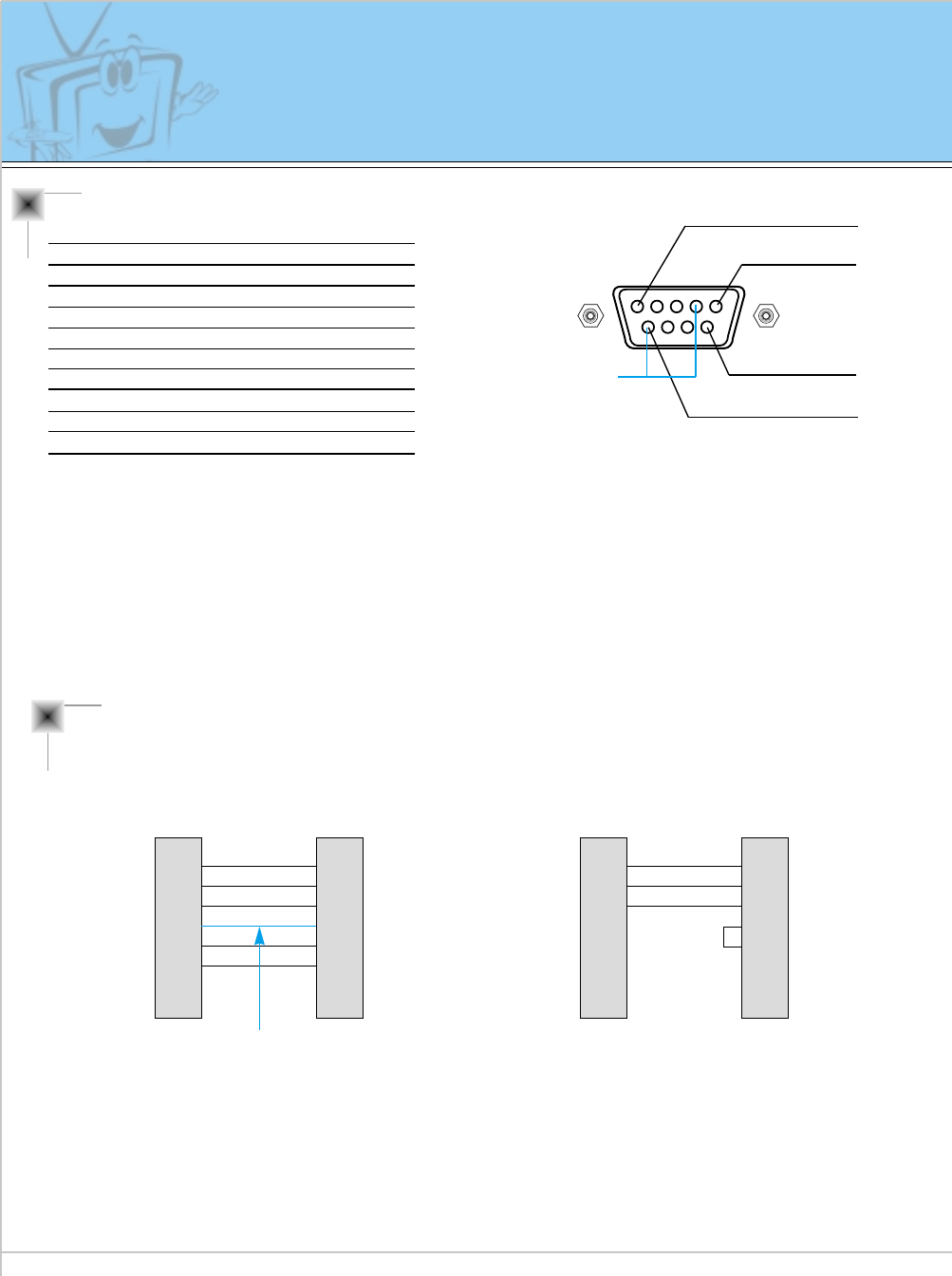
Type of connector : D-Sub 9-pin male
* Use a null modem cable.
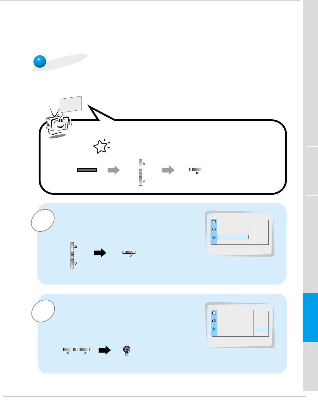
Wire the 7-Wire cable so that each pair of data lines cross between the two devices. These data line pairs
are RXD (Receive data) and TXD (Transmit data), DTR (DTE side ready) and DSR (DCE side ready), and
RTS (Ready to send) and CTS (Clear to send).
When using the 3-Wire cable connected to RXD, TXD and GND; Pin No. 4 (DTR) and Pin No. 6 (DSR)
must be connected to the monitor. (The cable must be disconnected from the Monitor to be able to use the
remote control and Monitor front panel controls.)
* With the RS-232 input connected, the Monitor cannot be controlled by both an external control device and
the remote control at the same time. The Monitor can only be controlled by either the remote control or the
external control device.
No. Pin name
1 No connection
2 RXD (Receive data)
3 TXD (Transmit data)
4 DTR (DTE side ready)
5 GND
6 DSR (DCE side ready)
7 RTS (Ready to send)
8 CTS (Clear to send)
9 No Connection
1
5
6
9
Pin No.4 and Pin
No.6 must be
connected on
monitor side.
RS-232C configurations
2
3
5
4
6
7
8
RXD
TXD
GND
DTR
DSR
RTS
CTS
TXD
RXD
GND
DSR
DTR
CTS
RTS
PC
7-wire configuration
(Standard RS-232C cable)
DB 9 Control line
3
2
5
6
4
8
7
PDP
DB 9
2
3
5
4
6
7
8
RXD
TXD
GND
DTR
DSR
RTS
CTS
TXD
RXD
GND
DTR
DSR
RTS
CTS
PC
3-wire configuration
(Not standard)
DB 9
3
2
5
4
6
7
8
PDP
DB 9
7-Wire Cable Configuration
• The Monitor is available to switch between external
adjustment and remote control adjustment using a
control line.
Note: If the control line is high, the monitor is con-
trolled by the external control device. If the control
line is low, the Monitor is controlled by the Monitor's
remote control.
3-Wire Cable Configuration
• When using a 3-Wire cable configuration there is no
control line. The external control device must put the
Monitor into the "change into remote control adjust-
ment mode" (see page 54). The Monitor will then be
able to be controlled by the remote control. If the
Monitor is turned back on, it will revert back to exter-
nal device control.
49
Safety instructions Monitor Overview Connections Basic operation Sleep timer Picture & Sound Special features Others
1Use the D / Ebuttons to select SET ID and
then press the Gbutton.
•Use this function to specify a monitor ID number.
SET ID
READY
2Use the F / Gbutton to adjust SET ID to
choose the desired monitor ID number.
•The adjustment range of SET ID is 1 ~ 99.
OSD ROTATE G
ARC G
SCREEN G
TRANSPARENCY G
PIP/DW G
SET ID G
COLOR TEMP. G
1
SET ID
OSD ROTATE G
ARC G
SCREEN G
TRANSPARENCY G
PIP/DW G
SET ID G
COLOR TEMP. G
1
1
MENU VOL
VOL
OK
VOL VOL
Press the MENU button and then press the D / Ebutton to
select menu. Press the Gbutton.
50
External Control Device Setup
Communication Parameters
Command Reference List
-The RS-232C input jack is used to control the Monitor’s functions using an external control device.
•Baud rate : 2400 bps (UART)
•Data length : 8 bits
•Parity : None
•Stop bit : 1 bit
•Communication code : ASCII code
* If the command interval is interrupted for more than 4
seconds, only Command 1 will be recognized.
Be careful when using the power command.
Transmission
* [Command] : To control PDP set.
* [Set ID] : You can adjust the set ID to choose
desired monitor ID number in special
menu. See page 49. Adjustment range
is 1 ~ 99.
When selecting Set ID ‘0’, every connected
PDP set is controlled.
* [DATA] : To transmit command data.
Transmit ‘FF’data to read status of
command.
* [Cr] : Carriage Return
ASCII code ‘0x0D’
* [ ] : ASCII code ‘space (0x20)’
[Command][ ][Set ID][ ][Data][Cr]
OK Acknowledgement
* The Monitor transmits ACK (acknowledgement) based
on this format when receiving normal data. At this
time, if the data is data read mode, it indicates present
status data. If the data is data write mode, it returns
the data of the PC computer.
[Set ID][:][OK][x][Data][x]
Error Acknowledgement
* The Monitor transmits ACK (acknowledgement) based
on this format when receiving abnormal data from
non-viable functions or communication errors.
[Set ID][:][NG][x]
Transmission / Receiving Protocol
NAME COMMAND DATA RANGE
01. Power p 0 ~ 1
02. Input Select i 0 ~ 3
03. Aspect Ratio r 0 ~ 2
04. Screen mute m 0 ~ 1
05. Volume mute w 0 ~ 1
06. Volume control v 0 ~ 64
07. Contrast k 0 ~ 64
08. Brightness b 0 ~ 64
09. Color c 0 ~ 64
10. Tint t 0 ~ 64
11. Sharpness s 0 ~ 64
12. OSD select d 0 ~ 1
13. Abnormal state a 0 ~ 1
14. PIP/DW z 0 ~ 3
15. PIP input select e 0 ~ 1
16. PIP sound select u 0 ~ 1
17. PIP position x 0 ~ 3
18. remote control j 0 ~ 1
adjustment mode
51
Safety instructions Monitor Overview Connections Basic operation Sleep timer Picture & Sound Special features Others
01. Power (Command:p)
GTo control Power On/Off of the Monitor.
Transmission
Data 0 : Power Off
1 : Power On
* Example : Power on for set ID No.3.
Type : P 3 1 ‘0x0D’
[p][ ][Set ID][ ][Data][Cr]
Acknowledgement
Data 0 : Power Off
1 : Power On
* In example : Monitor Acknowledges power on for set ID
No.3.
[Set ID][:][OK][x][Data][x]
02. Input select (Command:i)
GTo select input source for the Monitor.
You can also select an input source using the INPUT
SELECT button on the Monitor's remote control.
Transmission
Data 0 : RGB
1 : AV (Video)
2 : Component
3 : S-AV (S-Video)
[i][ ][Set ID][ ][Data][Cr]
Acknowledgement
Data 0 : RGB
1 : AV (Video)
2 : Component
3 : S-AV (S-Video)
[Set ID][:][OK][x][Data][x]
GTo show Power On/Off.
Transmission
[p][ ][Set ID][ ][FF][Cr]
Acknowledgement
Data 0 : Power Off
1 : Power On (RGB)
2 : Power On (Video)
3 : Power On (Component)
4 : Power On (S-Video)
* In like manner, if other functions transmit ‘FF’data
based on this format, Acknowledgement data feed
back presents status about each function.
[Set ID][:][OK][x][Data][x]
03. Aspect Ratio (Command:r)
GTo adjust the screen format.
You can also adjust the screen format using the ARC
(Aspect Ratio Control) button on remote control or in
the Special menu.
Transmission
Data 0 : Wide screen (16:9)
1 : Normal screen (4:3)
2 : Full screen (Zoom)
[r][ ][Set ID][ ][Data][Cr]
Acknowledgement
Data 0 : Wide screen (16:9)
1 : Normal screen (4:3)
2 : Full screen (Zoom)
* Using the PC input, you select either 16:9 or 4:3 screen
aspect ratio.
* Using the DTV 720p/1080i input, you can only select
16:9 screen aspect ratio.
[Set ID][:][OK][x][Data][x]
04. Screen mute (Command:m)
GTo select screen mute on/off.
Transmission
Data 0 : Screen mute on (Picture off)
1 : Screen mute off (Picture on)
[m][ ][Set ID][ ][Data][Cr]
Acknowledgement
Data 0 : Screen mute on (Picture off)
1 : Screen mute off (Picture on)
[Set ID][:][OK][x][Data][x]
05. Volume mute (Command:w)
GTo control volume mute on/off.
You can also adjust mute using the MUTE button on
remote control.
Transmission
Data 0 : Volume mute on (Volume off)
1 : Volume mute off (Volume on)
[w][ ][Set ID][ ][Data][Cr]
Acknowledgement
Data 0 : Volume mute on (Volume off)
1 : Volume mute off (Volume on)
[Set ID][:][OK][x][Data][x]
52
External Control Device Setup
* Real data mapping
0 : Step 0
A : Step 10
F : Step 15
10 : Step 16
64 : Step 100
06. Volume control (Command:v)
GTo adjust volume.
You can also adjust volume with the volume buttons
on remote control.
Transmission
Data Min : 0 ~ Max : 64
* Refer to ‘Real data mapping’as shown below.
[v][ ][Set ID][ ][Data][Cr]
Acknowledgement
Data Min : 0 ~ Max : 64
[Set ID][:][OK][x][Data][x]
07. Contrast (Command:k)
GTo adjust screen contrast.
You can also adjust contrast in the Picture menu.
Transmission
Data Min : 0 ~ Max : 64
* Refer to ‘Real data mapping’as shown below.
[k][ ][Set ID][ ][Data][Cr]
Acknowledgement
Data Min : 0 ~ Max : 64
[Set ID][:][OK][x][Data][x]
08. Brightness (Command:b)
GTo adjust screen brightness.
You can also adjust brightness in the Picture menu.
Transmission
Data Min : 0 ~ Max : 64
* Refer to ‘Real data mapping’as shown below.
[b][ ][Set ID][ ][Data][Cr]
Acknowledgement
Data Min : 0 ~ Max : 64
[Set ID][:][OK][x][Data][x]
09. Color (Command:c)
GTo adjust the screen color.
You can also adjust color in the Picture menu.
Transmission
Data Min : 0 ~ Max : 64
* Refer to ‘Real data mapping’as shown below.
[c][ ][Set ID][ ][Data][Cr]
Acknowledgement
Data Min : 0 ~ Max : 64
[Set ID][:][OK][x][Data][x]
10. Tint (Command:t)
GTo adjust the screen tint.
You can also adjust tint in the Picture menu
Transmission
Data Red : 0 ~ Green : 64
* Refer to ‘Real data mapping’as shown below.
[t][ ][Set ID][ ][Data][Cr]
Acknowledgement
Data Red : 0 ~ Green : 64
[Set ID][:][OK][x][Data][x]
11. Sharpness (Command:s)
GTo adjust the screen sharpness.
You can also adjust sharpness in the Picture menu
Transmission
Data Min : 0 ~ Max : 64
* Refer to ‘Real data mapping’as shown below.
[s][ ][Set ID][ ][Data][Cr]
Acknowledgement
Data Min : 0 ~ Max : 64
[Set ID][:][OK][x][Data][x]
53
Safety instructions Monitor Overview Connections Basic operation Sleep timer Picture & Sound Special features Others
12. OSD select (Command:d)
GTo select OSD (On Screen Display) on/off.
Transmission
* The remote control and Monitor front panel controls
(except main power) are not operable when the Monitor
is set up to be controlled by the PC computer.
* This function is “read only”.
Data 0 : OSD off
1 : OSD on
[d][ ][Set ID][ ][Data][Cr]
Acknowledgement
Data 0 : OSD off
1 : OSD on
[Set ID][:][OK][x][Data][x]
13. Abnormal state (Command:a)
GTo recognize an abnormal state.
Transmission
[a][ ][Set ID][ ][FF][Cr]
Acknowledgement
Data 0 : OK
1 : Fan alarm
2 : 5V down
3 : AC down
[Set ID][:][OK][x][Data][x]
14. PIP / DW (Command:z)
GTo control PIP (Picture-in-Picture) or twin picture (DW).
You can also control PIP/DW using the pip/twin picture
button on remote control or in the Special menu.
Transmission
Data 0 : PIP/ DW off
1 : PIP (small)
2 : PIP (large)
3 : Twin picture (DW)
[z][ ][Set ID][ ][Data][Cr]
Acknowledgement
Data 0 : PIP/ DW off
1 : PIP (small)
2 : PIP (large)
3 : Twin picture (DW)
* PIP only works in the following resolutions:
RGB PC 640x480 (VGA) / 800x600(SVGA) / 1024x768
(XGA) (only in vertical frequency 60Hz),
Component 480p / 720p / 1080i.
* Twin picture works only in the following resolutions:
RGB PC 640x480 (VGA) (only in vertical frequency 60Hz),
RGB DTV, Component 480p/720p/1080i.
[Set ID][:][OK][x][Data][x]
15. PIP input select (Command:e)
G To select input source for sub picture in PIP mode.
You can also select source using PIP input button on
the remote control or in the Special menu.
Transmission
* COMPONENT source only works with 480i input signal.
Data 0 : VIDEO
1 : COMPONENT
2 : S-VIDEO
[e][ ][Set ID][ ][Data][Cr]
Acknowledgement
Data 0 : VIDEO
1 : COMPONENT
2 : S-VIDEO
[Set ID][:][OK][x][Data][x]
54
* COMPONENT source only works in 480i input signal.
16. PIP sound select (Command:u)
G To select main or sub (inset) sound for PIP/Twin picture.
You can also select sound select in PIP/DW on the
special menu.
Transmission
[u][ ][Set ID][ ][Data][Cr]
Acknowledgement
Data 0 : Main picture sound
1 : Sub picture sound
Data 0 : Main picture sound
1 : Sub picture sound
[Set ID][:][OK][x][Data][x]
* If external equipment commands the Monitor to
"change into remote control adjustment mode", the
Monitor can only be adjusted by the remote control.
To revert the Monitor control to external control device
adjustment, turn the Monitor off and then on again.
18. Change into Remote control
adjustment mode (Command:j)
G To control the Monitor with the remote control while
the cable is still connected.
Transmission
[j][ ][Set ID][ ][Data][Cr]
Acknowledgement
Data 0 : PC adjustment mode
1 : Remote control adjustment mode
Data 1 : Remote control adjustment mode
[Set ID][:][OK][x][Data][x]
17. PIP position (Command:x)
GTo select sub picture position for PIP.
You can also adjust the sub picture position using the
position button on the remote control or in PIP/DW on
the Special menu.
Transmission
Data 0 : Right down on screen
1 : Left down on screen
2 : Left up on screen
3 : Right up on screen
[x][ ][Set ID][ ][Data][Cr]
Acknowledgement
Data 0 : Right down on screen
1 : Left down on screen
2 : Left up on screen
3 : Right up on screen
[Set ID][:][OK][x][Data][x]
External Control Device Setup
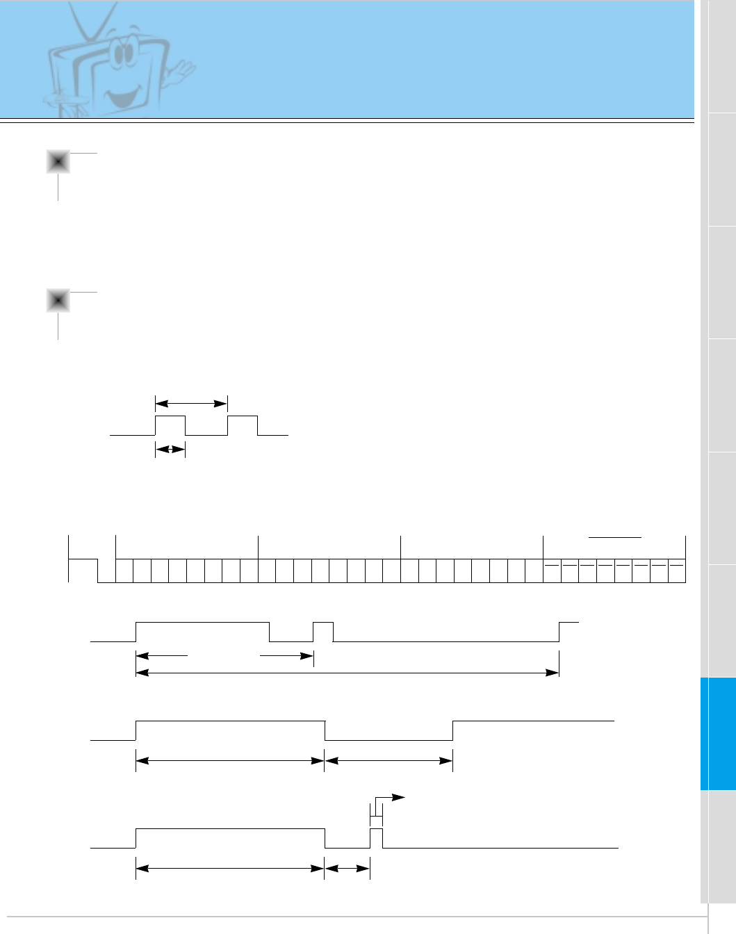
55
Safety instructions Monitor Overview Connections Basic operation Sleep timer Picture & Sound Special features Others
IR CODE (NEC Format)
G Connect your wired remote control to remote control jack of the monitor.
Set the CONTROL LOCK ‘ON’on the monitor back panel to work wired remote control.
Remote Control IR Code (NEC Format)
How to connect
G Output waveform
Single pulse, modulated with 37.917KHz signal at 455KHz
G Configuration of frame
G Repeat code
G Lead code
• 1st frame
Low
custom code
Lead
code High
custom code Data code Data code
TC
Tf
T1
C0
Carrier frequency
FCAR = 1/TC= fOSC/12
Duty ratio = T1/TC= 1/3
• Repeat frame
C1 C2 C3 C4 C5 C6 C7 C0 C1 C2 C3 C4 C5 C6 C7 D0 D1 D2 D3 D4 D5 D6 D7 D0 D1 D2 D3 D4 D5 D6 D7
Repeat code
9 ms 4.5 ms
0.55 ms
9 ms
2.25 ms
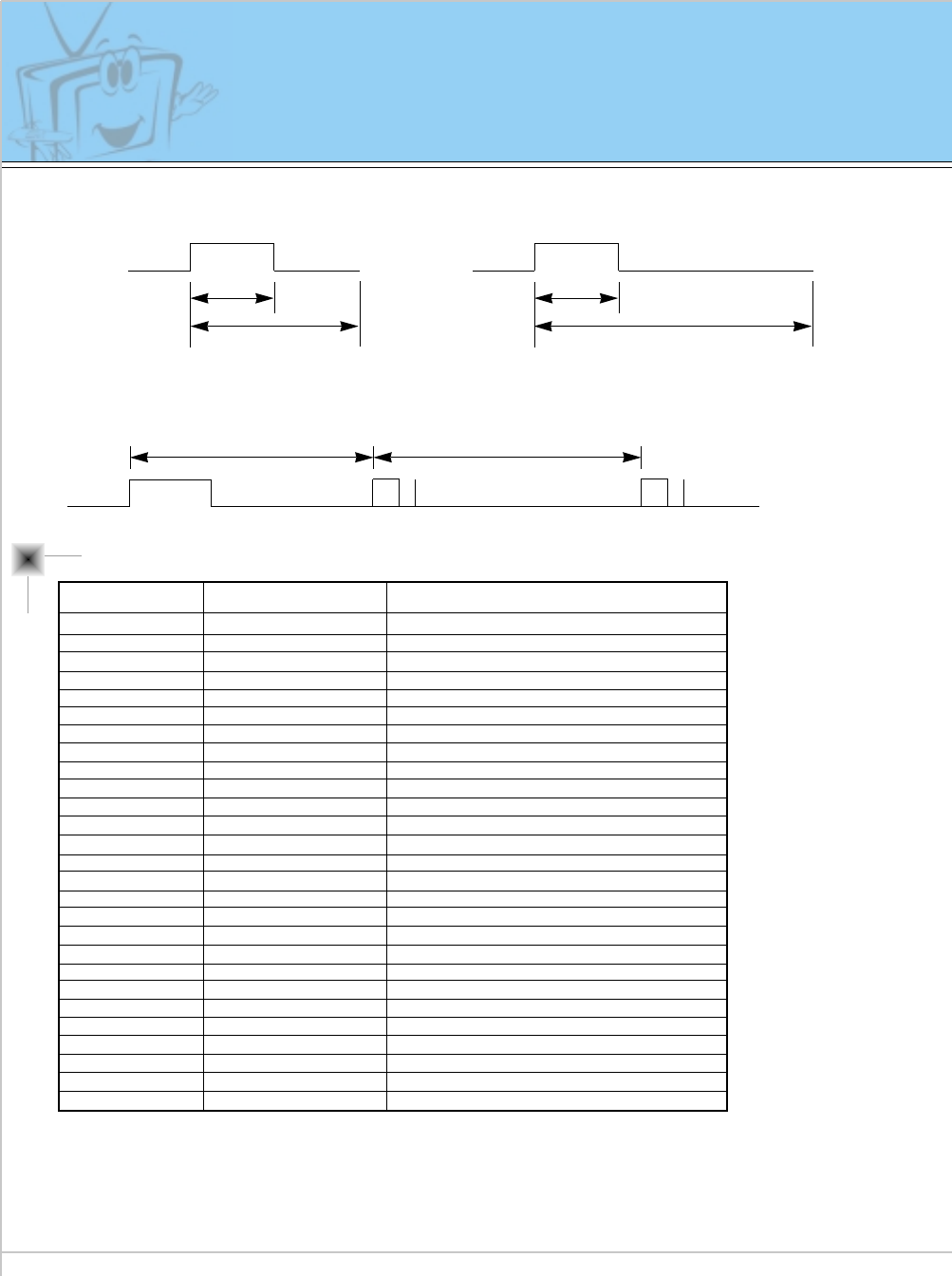
56
IR CODE (NEC Format)
UP (D)
DOWN (E)
VOL+ (G)
VOL- (F)
POWER
POWER ON
SYSTEM OFF
MUTE
INPUT SELECT
RGB
VIDEO
S-VIDEO
COMPONENT
SLEEP
OK (Á)
MENU
DASP
APC
PIP
PIP INPUT
(PIP)POSITION
STILL
TWIN PICTURE
ARC
ARC (16: 9)
ARC (4 : 3)
ARC (ZOOM)
00H
01H
02H
03H
08H
C4H
C5H
09H
0BH
98H
5AH
51H
BFH
0EH
1BH or 44H
42H
47H
4DH
60H
61H
62H
65H or BCH
6BH
79H
77H
76H
AFH
R/C Button
R/C Button
R/C Button
R/C Button
R/C Button (Power On/Off)
Discrete (Only Power On)
Discrete (Only System Off)
R/C Button
R/C Button
Discrete (Input RGB & Power On)
Discrete (Input VIDEO & Power On)
Discrete (Input S-VIDEO & Power On)
Discrete (Input COMPONENT & Power On)
R/C Button
R/C Button
R/C Button
R/C Button
R/C Button
R/C Button
R/C Button
R/C Button
R/C Button
R/C Button
R/C Button
Discrete (Only 16:9 mode)
Discrete (Only 4:3 mode)
Discrete (Only ZOOM mode)
Code (Hexa) Function Note
G Bit description
G Frame interval : Tf
The waveform is transmitted as long as a key is depressed.
• Bit “0”
Tf Tf
Tf=108ms @455KHz
0.56 ms 0.56 ms
1.12 ms
• Bit “1”
2.24 ms
57
Safety instructions Monitor Overview Connections Basic operation Sleep timer Picture & Sound Special features Others
Maintenance
Cleaning the screen
1. Here’s a great way to keep the dust off your screen for a while. Wet a
soft cloth in a mixture of lukewarm water and a little fabric softener or
dish washing detergent. Wring the cloth until it’s almost dry, and then
use it to wipe the screen.
2. Make sure the excess water is off the screen, and then let it air-dry
before you turn on your Monitor.
Cleaning the cabinet
To remove dirt or dust, wipe the cabinet with a soft, dry, lint-free cloth.
Please be sure not to use a wet cloth.
Extended absence
If you leave your Monitor dormant for a long time (such as a
vacation), it’s a good idea to unplug the power cord to protect
against possible damage from lightning or power surges.
- Early malfunction can be prevented. Careful and regular cleaning can extend the amount of
time you will have with your new Monitor. Be sure to turn the power off and unplug the
power cord before you begin any cleaning.
58
No output from one
of the speakers •Adjust BALANCE in the SOUND menu. (Refer to p.39)
Troubleshooting check list
No picture &
No sound
•Check whether the Monitor is turned on.
•Power cord inserted into wall outlet?
•Plug another product’s power cord into the wall outlet where
the Monitor’s power cord was plugged in.
No or Poor color
or Poor picture
•Select COLOR in the PICTURE menu and press the VOL-
UME (G) button. (Refer to p.37)
•Increase the distance between the Monitor and the VCR.
•Activate any function to restore the brightness of the picture.
(If still picture is on the screen for more than 5 minutes, the
screen gets dark.)
The remote control
doesn’t work
•Check to see if there is any object between the Plasma
Display and the remote control causing obstruction.
•Check to see if the batteries are installed with the correct
polarities. (Refer to p.31)
•Install new batteries. (Refer to p.31)
Picture OK &
No sound
•Press the VOLUME (G) button.
•Sound muted? Press MUTE button.
59
Safety instructions Monitor Overview Connections Basic operation Sleep timer Picture & Sound Special features Others
Product specifications
MODEL
Width (inches / mm)
Height (inches / mm)
Depth (inches / mm)
Weight (pounds / kg)
Power requirement
Resolution
Color
Temperature (In operation)
Humidity (In operation)
MU-60PZ12M/MA/MB/MK/MS
MU-60PZ12V/VA/VB/VK/VS
57.3 / 1455
34.8 / 883
3.9 / 99
154.3 / 70
120V, 60Hz
1280 x 720 (Dot)
16,770,000 (256 steps of each R, G and B)
0 ~ 40°C
under 80%
•The specifications shown above may be changed without prior notice for
quality improvement.
PLASMA MONITOR
ON/OFF INPUT
SELECT VOLUME
P/NO : 3828VA0277W
(NP00KB)
PLASMA MONITOR
Please read this owner’s manual carefully before
operating the Monitor.
Retain it for future reference.
Record model number and serial number of the
Monitor.
See the label attached on the back of the Monitor
and quote this information to your dealer when you
require service.
Model number :
Serial number :
MU-60PZ12M/12V
MU-60PZ12MA/12VA
MU-60PZ12MB/12VB
MU-60PZ12MK/12VK
MU-60PZ12MS/12VS
OWNER’S MANUAL
a