LG Electronics USA MW30LZ10 LCD A/V Monitor User Manual
LG Electronics USA LCD A/V Monitor
user manual
P/NO : 3828VA0338G(373-026H)
MW-30LZ10
OWNER’S MANUAL
LCD AV MONITORLCD AV MONITOR
Please read this manual carefully before oper-
ating your set.
Retain it for future reference.
Record model number and serial number of
the set.
See the label attached on the back of the set
and quote this information to your dealer when
you require service.
Model number :
Serial number :
Multimedia Display
This LCD monitor can be connected to a PC in place of the PC Monitor.
The LCD Display panel
The panel is composed of 2.9 million individual cells and a few defective cells are likely to appear as
coloured dots on the screen as a result of the manufacturing process. This tolerance of upto six defective
cells has been adopted by all panel manufacturers and therefore would not be considered as reason for
exchange or refund.
FCC NOTICE
• A Class B digital device
This equipment has been tested and found to comply with the limits for a Class B digital device, pursuant
to Part 15 of the FCC Rules. These limits are designed to provide reasonable protection against harmful
interference in a residential installation. This equipment generates, uses and can radiate radio frequency
energy and, if not installed and used in accordance with the instructions, may cause harmful interference
to radio communications. However, there is no guarantee that interference will not occur in a particular
installation. If this equipment does cause harmful interference to radio or television reception, which can
be determined by turning the equipment off and on, the user is encouraged to try to correct the interfer-
ence by one or more of the following measures:
- Reorient or relocate the receiving antenna.
- Increase the separation between the equipment and receiver.
- Connect the equipment into an outlet on a circuit different from that to which the receiver is connected.
- Consult the dealer or an experienced radio/TV technician for help.
• Any changes or modifications not expressly approved by the party responsible for compliance
could void the user’s authority to operate the equipment.
Warning
This is a class B product. In a domestic environment this product may cause radio interfer-
ence, in which case the user may be required to take adequate measures.

Keep this manual
with Monitor for
future easy refer-
ence
Table of Contents
First step
Safety instructions ....................................................4
Monitor Overview
Front Panel Controls ..............................................12
Connection Panel Overview ...................................13
Remote Control Key Functions ..............................14
Accesories/Optinal extra.........................................16
Using the remote control ........................................17
Equipment Connections and Setup
VCR Setup..............................................................18
Cable TV Setup ......................................................20
External AV Source Setup ......................................21
DVD Setup..............................................................22
DTV Setup..............................................................23
Connecting to a wireless transmitter(option)..........24
Connecting to a wireless receiver(option) ..............25
PC Setup ................................................................26
Basic Features Setup and Operation
Turning on the Monitor ...........................................29
Checking features...................................................30
Sleep Timer
Setting Sleep Timer ................................................31
Picture & Sound
Auto picture control ................................................32
Adjusting picture appearance.................................33
Auto Sound Control ................................................34
Adjusting Sound: Bass, Treble, Balance ................35
Special Features
Selecting language for the menus..........................36
Adjusting color temperature ...................................37
Using the screen saver function.............................38
Setting picture format .............................................39
Using the Zoom in/out function ..............................40
Moving the picture ..................................................41
Picture In Picture(PIP) function ..............................42
Zoom in/out main picture........................................44
Twin picture function...............................................45
Using the screen options........................................47
PC Mode feature check..........................................48
PC Mode adjustment..............................................49
External control device setup .................................51
Others
Troubleshooting check list......................................59
Note ........................................................................61
Product specifications.............................................63
4
Safety Instructions
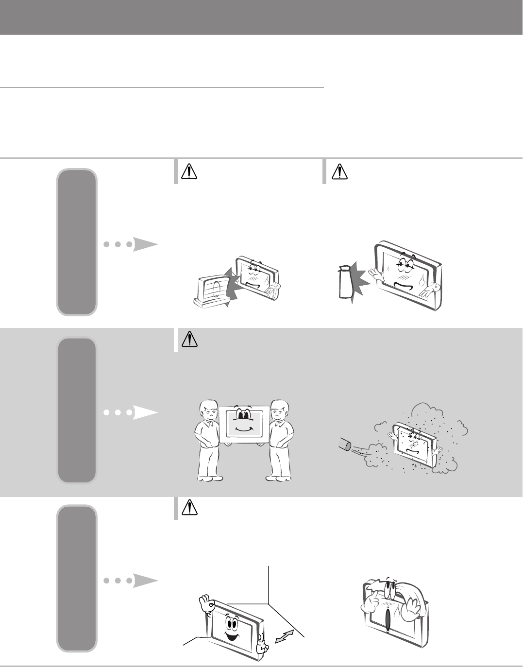
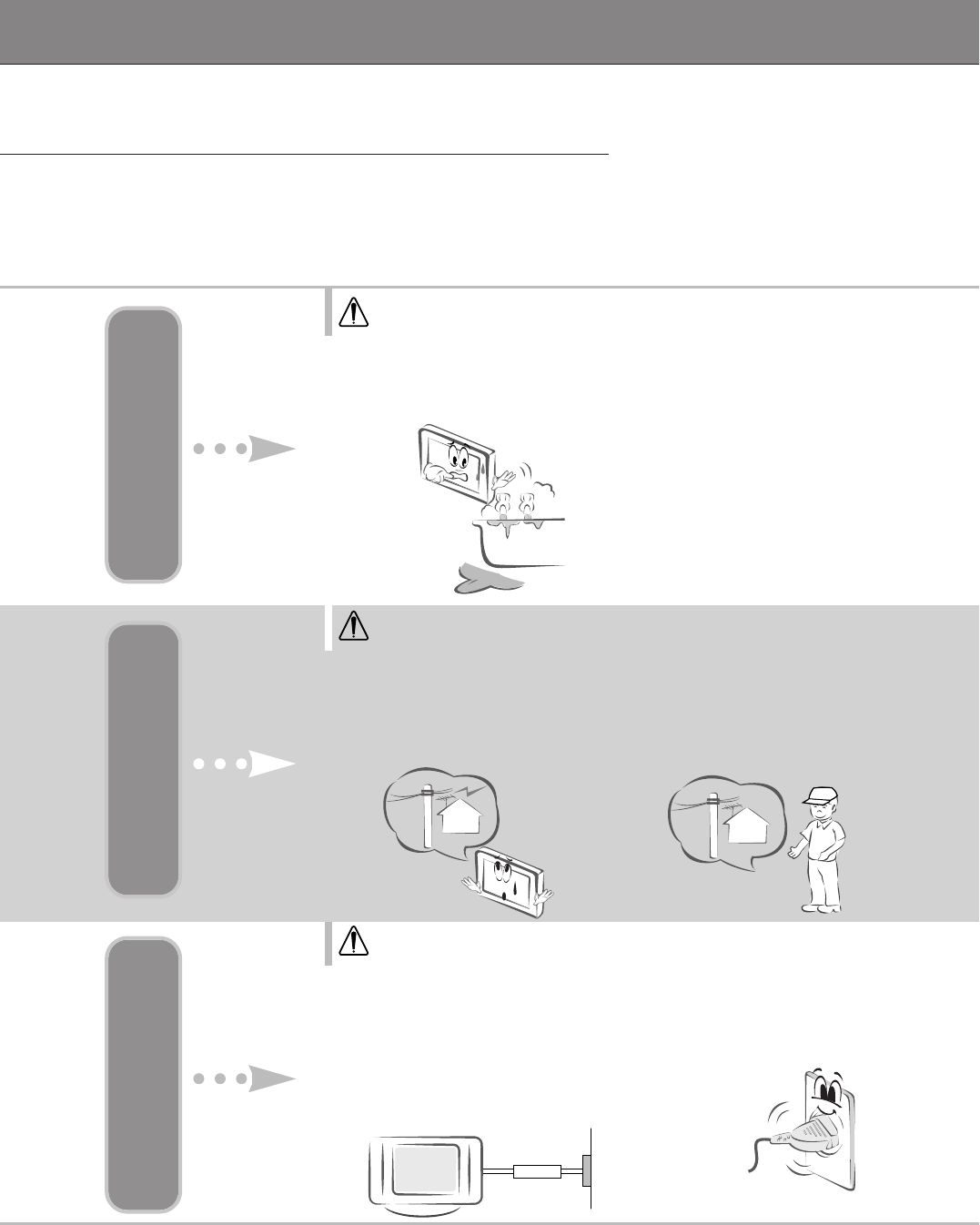
WARNING
Do not place the Monitor in
direct sunlight or near heat
sources such as radiators, fires
and stove etc.
-This may cause a fire hazard !
NOTES
NOTES
Indoor Installation Indoor Installation Indoor Installation
NOTES
Do not place inflammable materi-
als beside the monitor
-This may cause a fire hazard !
When unpacking or moving
the Monitor two people will be
necessary to lift it safely.
Do not place the monitor where
it might be exposed to dust.
-This may cause a fire hazard !
Ensure good ventilation around
the monitor. The distance
between the monitor and the
wall should be more than 10cm.
-It make internal
temperature increase
and causes a fire.
Do not cover the vent grilles of
the monitor.
-This may cause a fire hazard !
5
ENGLISH
NOTES
NOTES
*Safety instructions have two kinds of information as illustrated below.
Take care of danger that may happen under specific condition.
The violation of this instruction may cause serious injuries and even death.
The violation of this instruction may cause light injuries or damage of the
product.
WARNING
NOTES
NOTES
Disconnect from the mains
and remove all connections
before moving.
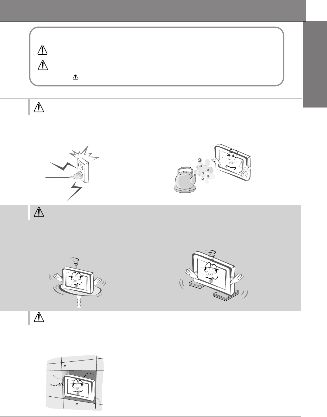
Only use the monitor on a
level and stable surface.
-It may fall down or be upset.
Do not place the monitor close to
sources of steam or oil such as a
humidifier.
-This may create a fire hazard or an
electric shock hazard !
When installing the monitor on a table, be
careful not to place it near the edge.
-This may cause the monitor to fall causing serious
injury to a child or adult and serious damage to the
monitor.
-Surely use a fitting table or rack.
Do not place the monitor directly on a carpet, rug or place
where ventilation is restricted.
-This would cause its internal temperature to increase and might
create a fire hazard !
6
Safety Instructions
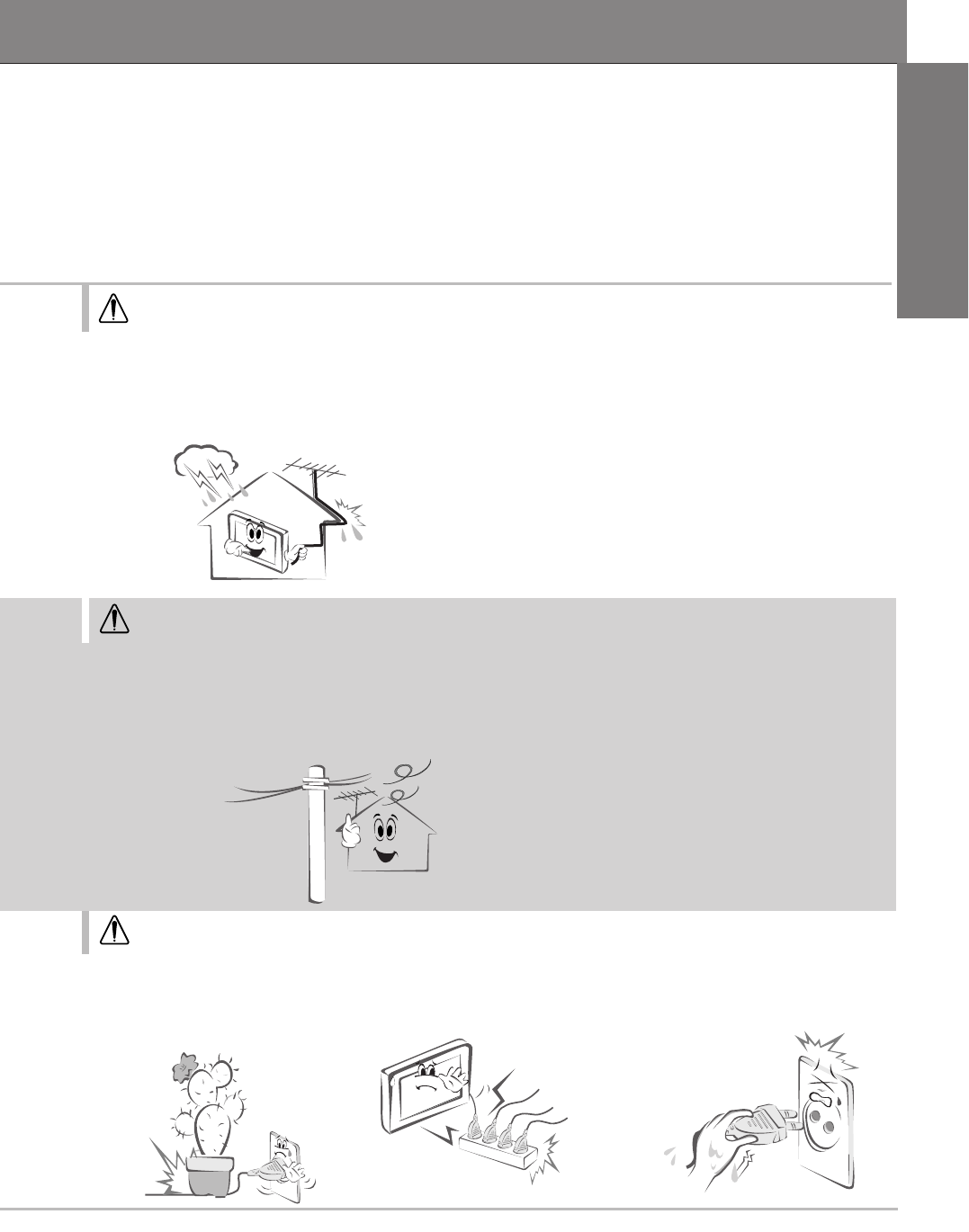
WARNING
WARNING
WARNING
Outdoor Installation Outdoor Installation Power
Do not use the Monitor in a damp place such as a bathroom
where it is likely to get wet.
-This may cause a fire or an electric shock hazard !
Earth wire should be connected.
-If the earth wire is not connected,
there is possible a danger of electric
shock caused by the current leakage.
- If grounding methods are not possi-
ble, a separate circuit breaker should
be employed and installed by a quali-
fied electrician.
- Do not connect ground to telephone
wires, lightning rods or gas pipe.
In case of using a receiver (VCR,
Digital Set Top Box), do not place an
antenna in the vicinity of power lines.
-This may cause an electric shock.
The mains plug should be
inserted fully into the
power outlet to avoid a fire
hazard !
-This may cause a fire hazard !
In case of using a receiver
(VCR, Digital Set Top Box),
contact your service center to
construct an antenna because
it needs skilled man.
-This may cause an electric shock.
7
ENGLISH
WARNING
NOTES
NOTES
In case of using a receiver (VCR, Digital Set Top Box), there should be
enough distance between an outside antenna and power lines to keep
the former from touching the latter even when the antenna falls.
-This may cause an electric shock.
In case of using a receiver (VCR, Digital Set Top Box), Bend antenna
cable between inside and outside building to prevent rain from flowing in.
-This may cause water damaged inside the Monitor and could give an electric shock.
Do not place heavy objects
on the power cord
-This may cause a fire or an electric
shock hazard !
Do not use too many plugs on
the Mains multi-outlet.
-It may result in overheating of the
outlet and causes a fire hazard !
Never touch the power plug
with a wet hand
-This may cause an electric shock
hazard !
8
Safety Instructions
NOTES
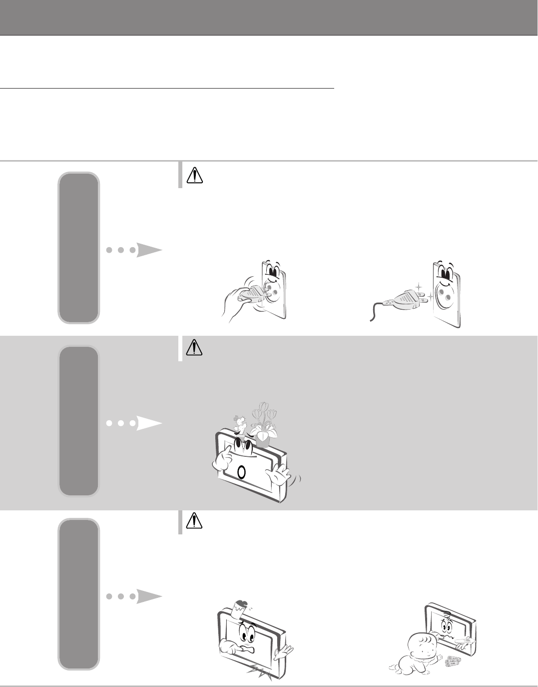
WARNING
WARNING
Power Using Using
Hold the plug firmly when
unplugging. If you pull the
cord the cord may be dam-
aged.
-This may cause a fire hazard !
Prevent dust collecting on the
power plug pins or outlet.
-This may cause a fire hazard !
Dispose of used batteries
carefully and safely.
-In the case of a battery being
swallowed by a child please con-
sult a doctor immediately.
Do not place anything containing liquid on top of the
monitor such as flowerpot, cup, cosmetics or candle.
-This may cause a fire hazard !
If water is spilt into the monitor
unplug it from the mains supply out-
let immediately and consult your
Service Agent.
-This may cause an electric shock hazard !
9
ENGLISH
NOTES
NOTES
NOTES
Ensure the power cord does not come
into contact with sharp or hot objects such
as a heater.
-This may cause a fire or an electric shock hazard !
Do not plug when the power cord or the plug is
damaged or the connecting part of the power
outlet is loose.
-This may cause a fire or an electric shock hazard !
Do not drop the monitor or allow impact shock.
-This may cause mechanical failure or injury !
In case of impact shock or damage to the monitor
switch it off and unplug it from the outlet and contact
your service center.
-This may cause a fire or an electric shock hazard !
Do not allow any objects to fall into the
monitor.
-This may cause an electric shock hazard !
10
Safety Instructions
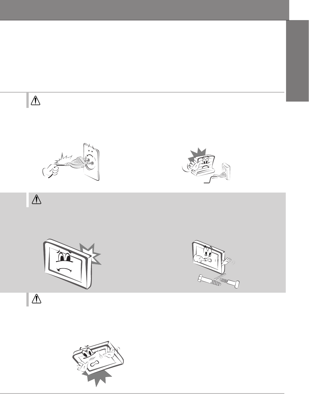
WARNING
WARNING
WARNING
Using Cleaning Others
Do not use water while
cleaning the Monitor
-This may cause damaged the
Monitor or an electric shock haz-
ard.
In the unlikely event of smoke
or a strange smell from the
Monitor, switch it off ,unplug it
from the wall outlet and contact
your dealer or service centre.
-This may cause a fire or an electric
shock hazard !
In the event that an image does not appear on the screen please
switch it off and unplug it from the mains suuply and contact your
Service Centre.
-This may cause a fire or an electric shock hazard !
In the event of a lightning or
thunder storm unplug the
Monitor and aerial from the
wall outlet.
-This will prevent damage to the
Monitor and possible electric shock.
Do not attempt to service
the Monitor yourself.
Contact your dealer or ser-
vice centre.
-This may cause damage to the
Monitor and could give an elec-
tric Shock as well as invalidating
the warranty !
11
ENGLISH
WARNING NOTES
NOTES
NOTES
Only use the specified bat-
teries.
-This make cause damaged the
Monitor or could give an electric
shock.
1.5V
1.5V
Contact the service center once a year to clean
the internal part of the monitor.
-- Accumulated dust can cause mechanical failure.
Do not watch the monitor while driving or
walking.
-This may cause an accident.
Unplug this product from the wall outlet
before cleaning. Do not use liquid clean-
ers or aerosol cleaners.
-This may cause damage to the Monitor or cause
an electric shock hazard !
Do not place heavy objects
on the Monitor.
-This may cause serious injury to
a child or adult.
The distance between eyes
and the screen should be
about 1.5m.
-If not, eyes will strain.
Unplug the Monitor from the
wall outlet when it is left
unattended and unused for
long periods of time.
-Accumulated dust may cause a
fire or an electric shock from
deterioration or
electric leakage.
12
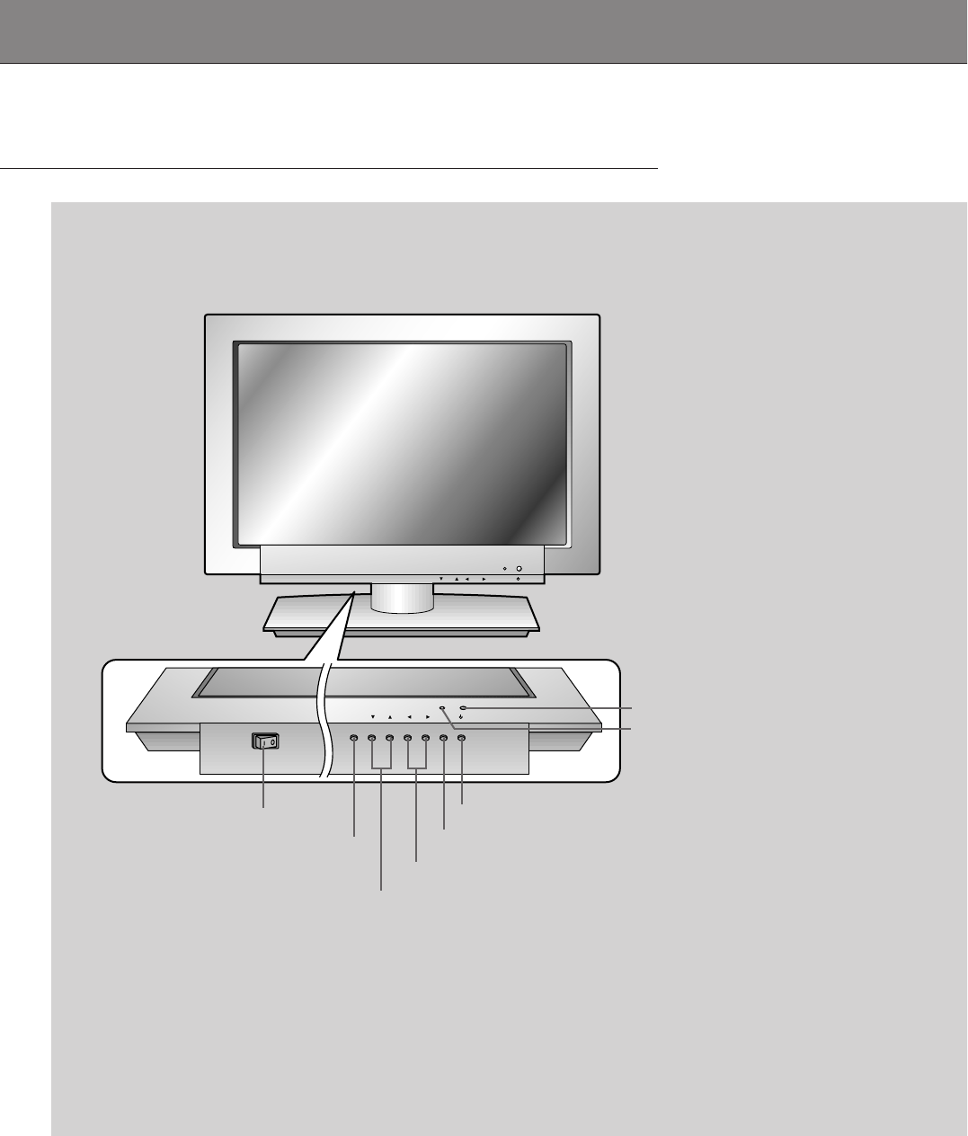
Front Panel Controls
ON OFF
/I
/I
ON OFF
POWER MENU VOL
POWER MENU VOL INPUT
SELECT
INPUT
SELECT
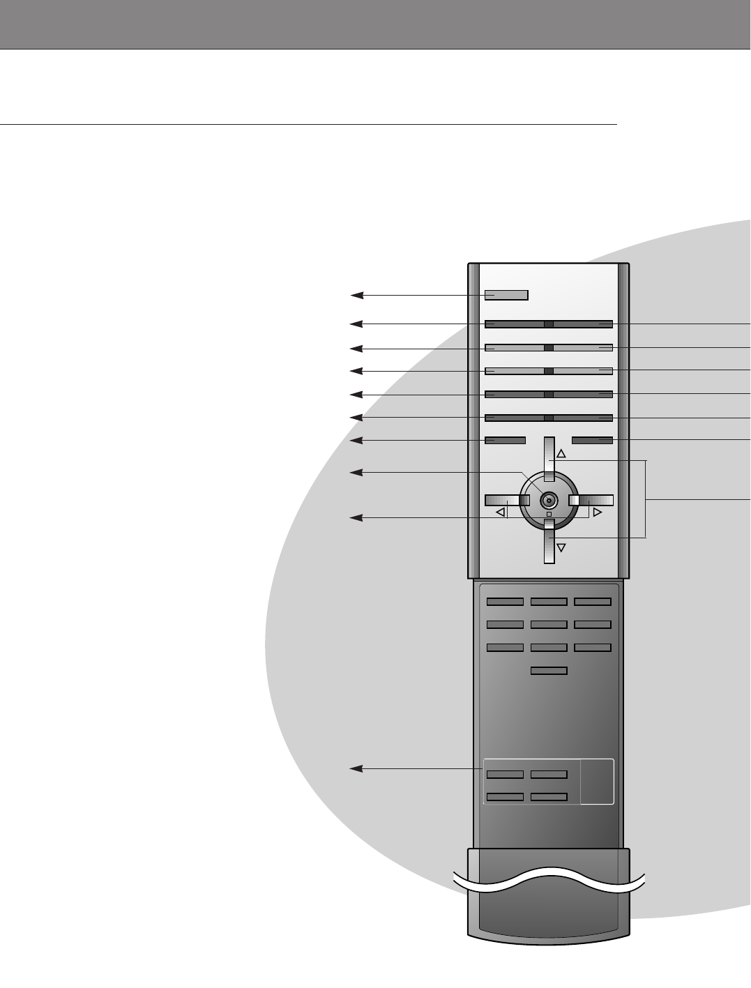
<Front Panel Controls>
Main power button
INPUT SELECT button
Power standby indicator
Illuminates orange in stand-
by mode, Illuminates green
when the Monitor is turned
on
Remote control sensor
MENU button
DD,EEbuttons
VOLUME (FF,GG) buttons
Sub power button
13
ENGLISH
Y PBPR
RLMONO
AUDIO VIDEO
S-VIDEO
AV INPUT COMPONENT (DVD/DTV INPUT)
AC INPUT
RL
AUDIO RGB 2 INPUT
(DIGITAL RGB INPUT) RGB 1 INPUT
(PC/DTV INPUT) RS 232C INPUT
(CONTROL/SERVICE)
DC OUTPUT
(DC 12V)
( ) ( )
( ) ( )
R
L
Ω
EXTERNAL SPEAKER(6 )
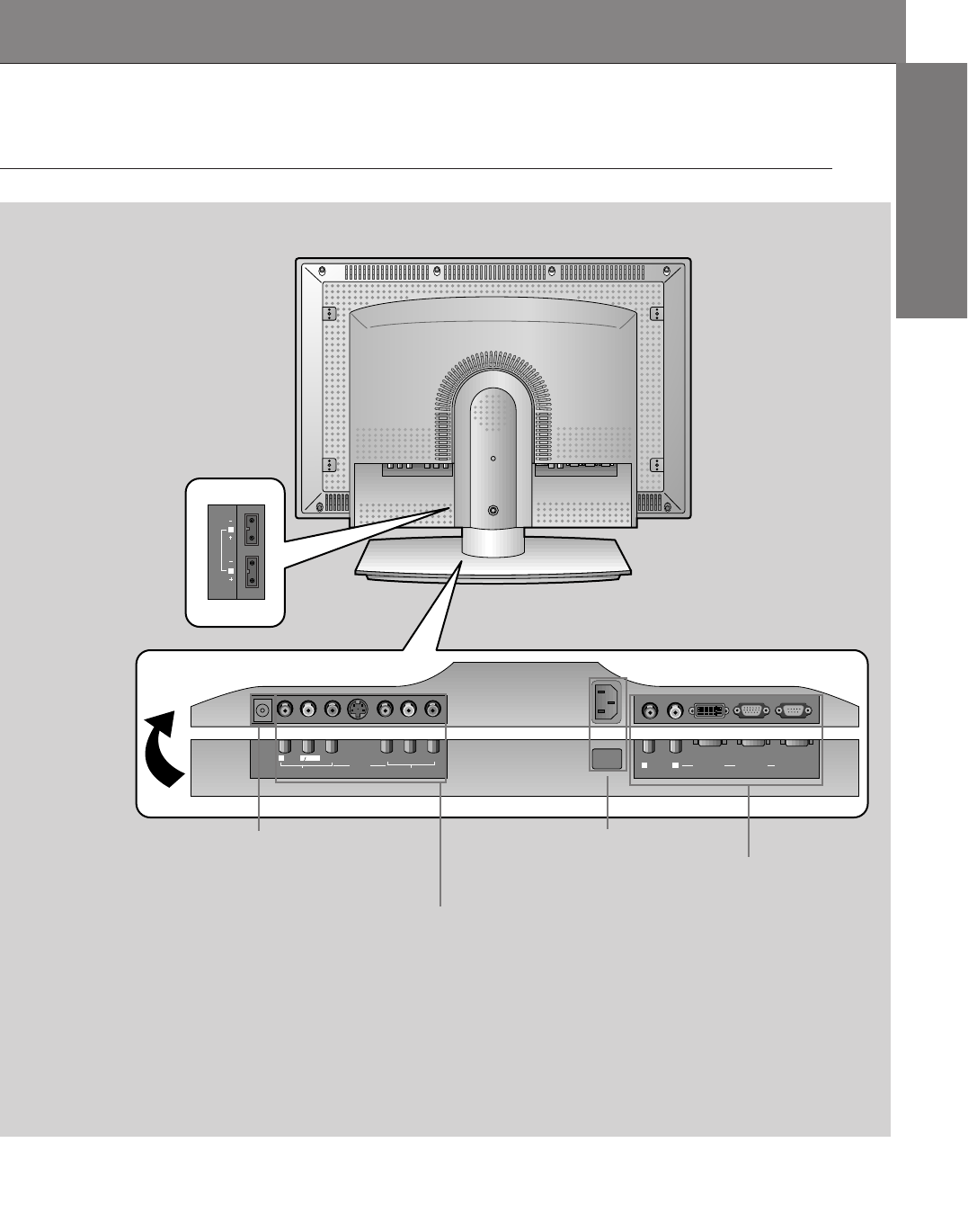
<Back Panel>
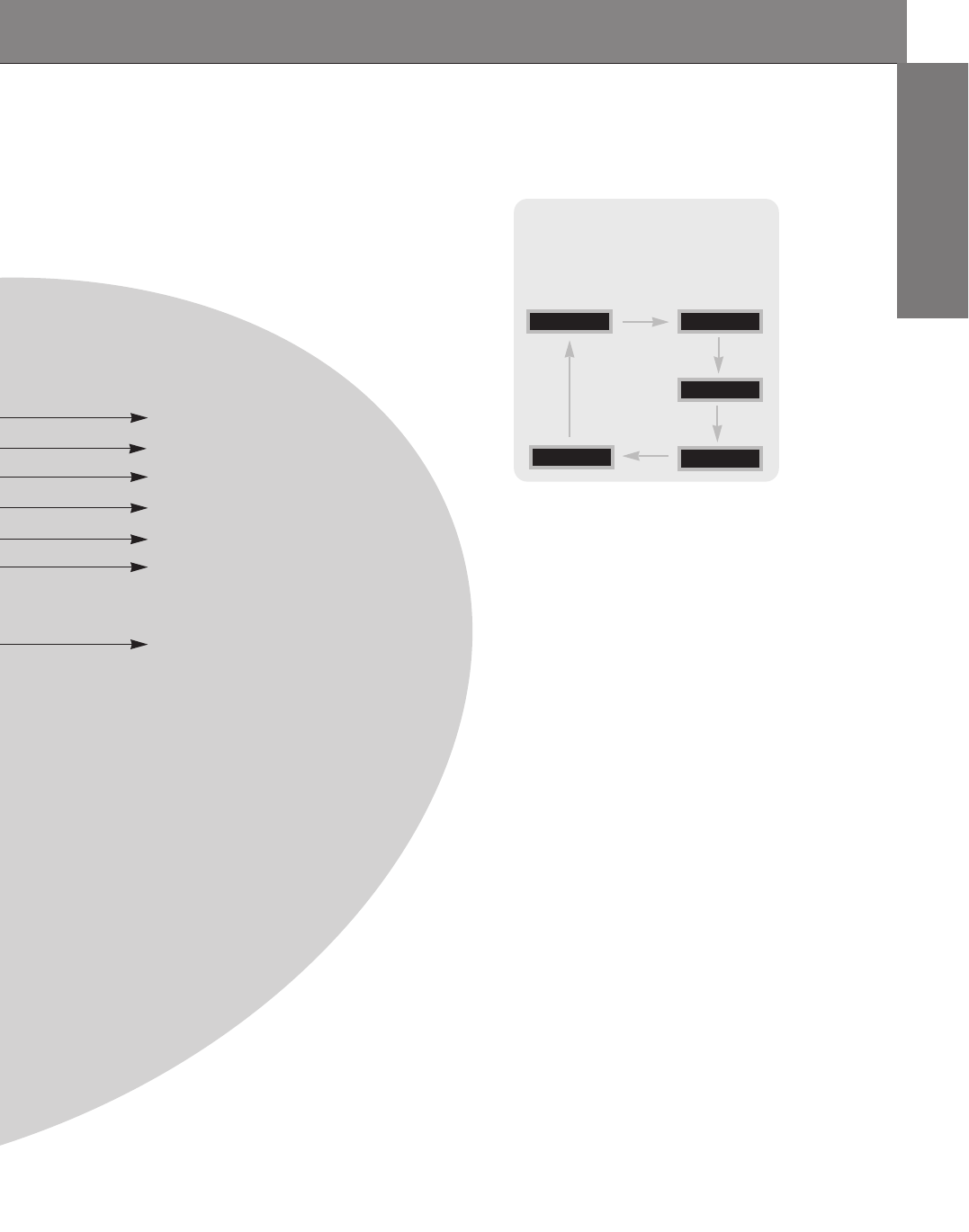
Connection Panel Overview
A/V Input / COMPONENT
(DVD/DTV) INPUT jacks /
S-video
Audio Input sound (R)(L)jacks
RGB-1 (PC/DTV INPUT)
RGB-2 (DIGITAL RGB INPUT) jack /
RS-232C jacks
AC INPUT jack
- Input RGB2(Digital RGB) when input
signal supporting DVI-D.
- You can use it from jacks.
DC OUTPUT (DC 12V) jack
- The DC OUTPUT jack is
optional item.
Remote Control Key Functions
-When using the remote control aim it at the remote control sensor on the Monitor.
14
1 2 3
4 5 6
7 8
0
9
SLEEP INPUT SELECT
POWER
APC DASP
ARC PIP ARC
PIP TWIN PICTURE
SWAP SUB INPUT
MENU MUTE
VOLVOL ENTER
ZOOM+
ZOOM-
WIN.SIZE
WIN.POSITION
VOL buttons
PIP button
ARC button
APC button
PIP buttons
SLEEP button (Refer to p. 31)
ENTER button
POWER button
SWAP button
MENU button
15
ENGLISH
input select button on the remote
control
Each press of this button changes the
mode as shown below.
RGB2
COMPONENT
RGB1
S-VIDEO
MUTE button
switches the sound on or off.
DASP button (Refer to p. 34)
PIP ARC select button
TWIN PICTURE button (Refer to p. 42~46)
VIDEO
INPUT SELECT button
SUB INPUT button
UP/DOWN buttons
16
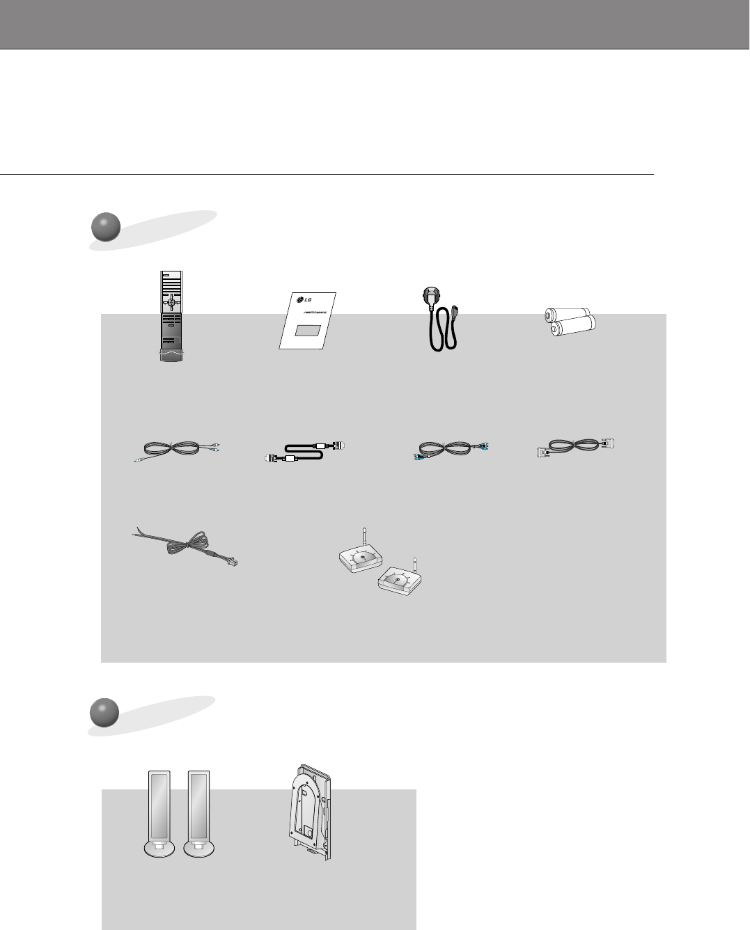
Accesories
D-sub 15 pin cable
Power cord
1 2 3
4 5 6
7 8
0
9
SLEEP INPUT SELECT
POWER
APC DASP
ARC PIP ARC
PIP TWIN PICTURE
SWAP SUB INPUT
MENU MUTE
VOLVOL ENTER
ZOOM+
ZOOM-
WIN.SIZE
WIN.POSITION
Remote control Owner’s Manual Alkaline batteries
DVI computer cablePC sound cable video cable
1.5V
1.5V
Speaker cable
Optional Extras
Speaker Tilt wall mounting braket
CH1 CH2 CH3
CH S/W
CH4CH1 CH2 CH3
CH S/W
CH4
A/V wireless
transmitter-receiver
(option)
CH1 CH2 CH3
CH S/W
CH4CH1 CH2 CH3
CH S/W
CH4
Accesories/Optional extras
17
ENGLISH
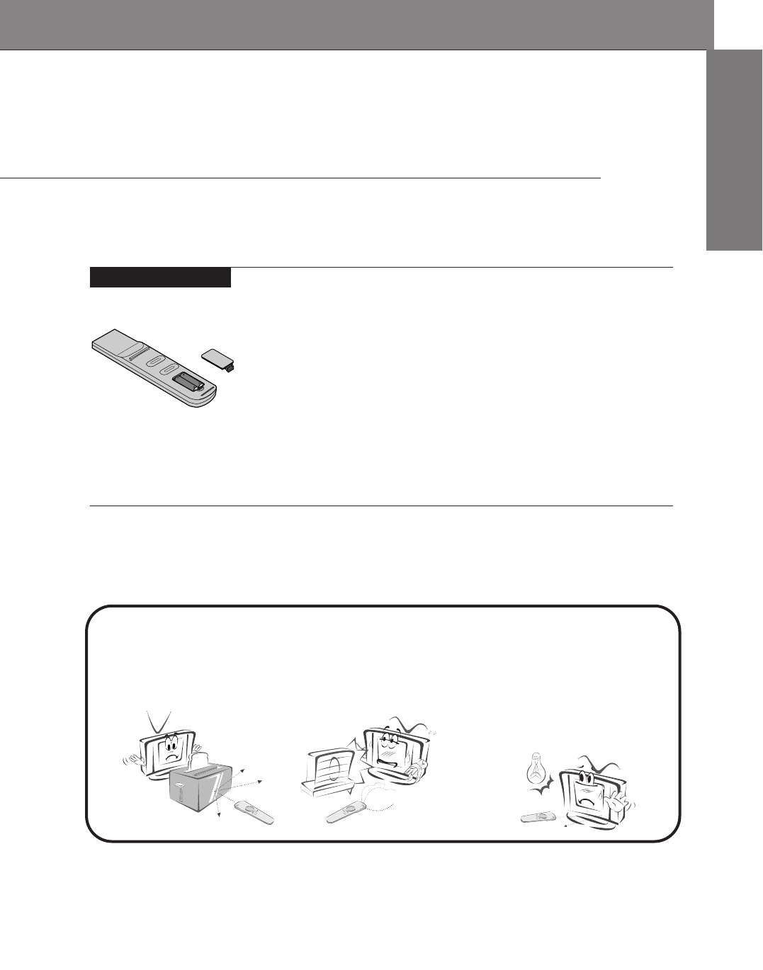
Using the remote control
Installing batteries
• Open the battery compartment cover on the back
of the remote control and insert the batteries with
correct polarity, match “+” with “+”, and match “-”
with “-”.
• Install two 1.5V “AAA” alkaline batteries.
Don’t mix used batteries with new batteries.
Notes for using the remote control
Make sure these are no
objects between the
remote control and its
sensor.
Don’t place the remote control
near a heater or damp place.
Strong impact on the remote con-
trol may cause operation failure.
Signal from the remote control
may be disturbed by sun light or
other strong light. In this case,
turn the set to other direction.
18
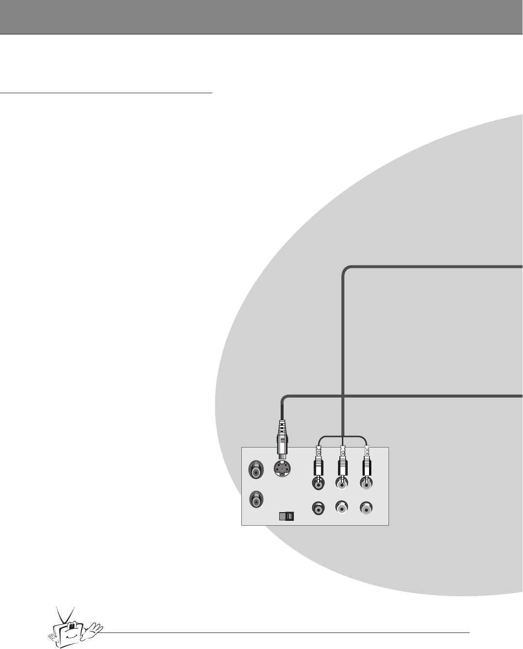
VCR Setup
Tips
• To avoid picture noise (interference), leave an adequate distance (20 inches or more)
between the VCR and monitor.
S-VIDEO OUT
IN
(R) AUDIO (L) VIDEO
Back panel of VCR
- As shown below, when connecting the Monitor to a VCR, match the colors of AV input
jacks on the Monitor with the output jacks on the VCR: Video = yellow, Audio (Left) =
white, Audio (Right) = red.
- If you have a mono VCR, connect the audio cable from the VCR to the AUDIO (L/MONO)
input of the Plasma Monitor.
- If you connect an S-VIDEO VCR to the S-VIDEO input, the picture quality is improved,
compared to connecting a regular VCR to the Video input.
- Avoid having a fixed image remain on the screen for a long period of time. A frozen still
picture from a VCR (or if a CH label is displayed) displayed on the screen for prolonged
periods will result in an image ghost remaining even when you change the image. Avoid
prolonged display of a still image.
19
ENGLISH
Y PBPR
RLMONO
AUDIO VIDEO
S-VIDEO
AV INPUT COMPONENT (DVD/DTV INPUT)
AC INPUT
RL
AUDIO RGB 2 INPUT
(DIGITAL RGB INPUT) RGB 1 INPUT
(PC/DTV INPUT) RS 232C INPUT
(CONTROL/SERVICE)
DC OUTPUT
(DC 12V)
Back panel of the Monitor
To watch VCR
Press INPUT SELECT button on the
remote control and select VIDEO.
(When connecting with S-Video, select the
S-VIDEO.)
1
Insert a video tape into the VCR and press
the PLAY button on the VCR. See VCR
owner’s manual.
2
INPUT SELECT
20
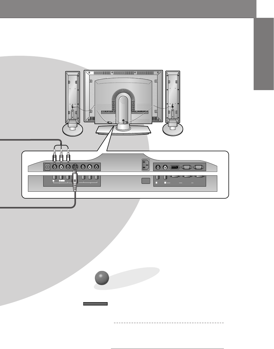
Cable TV Setup
- After subscribing to a cable TV service from a local provider and installing a converter,
you can watch cable TV programming. This monitor cannot display TV programming
without a TV tuner or cable TV converter box.
TV
VCR RF Cable
(R) AUDIO (L) VIDEO
Y PBPR
RLMONO
AUDIO VIDEO
S-VIDEO
AV INPUT COMPONENT (DVD/DTV INPUT)
AC INPUT
RL
AUDIO RGB 2 INPUT
(DIGITAL RGB INPUT) RGB 1 INPUT
(PC/DTV INPUT) RS 232C INPUT
(CONTROL/SERVICE)
DC OUTPUT
(DC 12V)
To watch cable TV
Press INPUT SELECT button on the
remote control and select VIDEO source.
1
Tune to cable service provided channels
using the cable box.
2
Tips
•For further information regarding cable TV service, contact your local
cable TV service provider(s).
Monitor back panel
Cable box
INPUT SELECT
21
ENGLISH
Y PBPR
RLMONO
AUDIO VIDEO
S-VIDEO
AV INPUT COMPONENT (DVD/DTV INPUT)
AC INPUT
RL
AUDIO RGB 2 INPUT
(DIGITAL RGB INPUT) RGB 1 INPUT
(PC/DTV INPUT) RS 232C INPUT
(CONTROL/SERVICE)
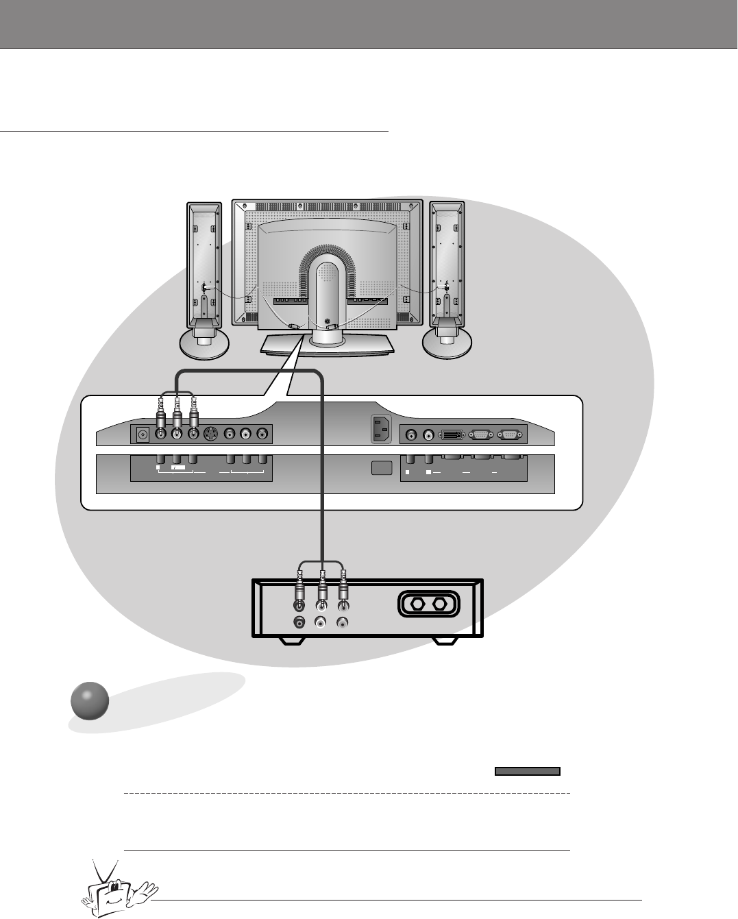
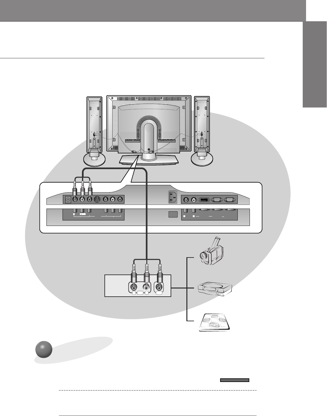
R L
AUDIO VIDEO
Camcorder
Video game set
DDR
DC OUTPUT
(DC 12V)
To watch external AV source
Press INPUT SELECT button on the
remote control of the monitor to select
VIDEO.
1
Operate the corresponding external equip-
ment. See external equipment operating
guide.
2
External AV Source Setup
- As shown below, when connecting the Monitor to an external source, match the
colors of AV input jacks on the Monitor with the output jacks on the audio/video
equipment: Video = yellow, Audio (Left) = white, Audio (Right) = red.
Back panel of the Monitor
INPUT SELECT
22
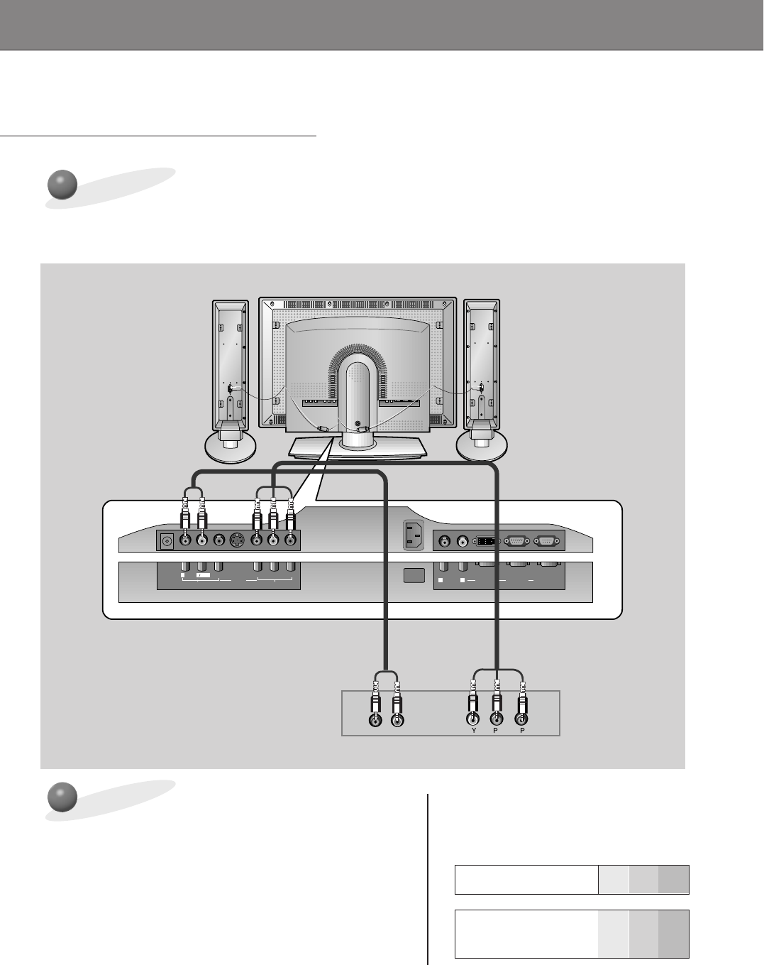
DVD Setup
• Connect DVD video inputs to Y, PB, PRof COMPONENT (DVD/DTV INPUT) and audio
inputs to Audio jacks of AV INPUT.
• Component Input is available to 480i, 480p, 720p, 1080i mode.
How to connect a DVD (digital video disk player)
How to use
•Press INPUT SELECT button on the remote control of the
monitor to select COMPONENT. Use the DVD player
according to its owner’s manual.
• Turn on the DVD player, and insert a DVD.
•Component Input ports
Connect DVD player jacks to Monitor
Component input jacks as indicated below.
Y PBPR
RLMONO
AUDIO VIDEO
S-VIDEO
AV INPUT COMPONENT (DVD/DTV INPUT)
AC INPUT
RL
AUDIO RGB 2 INPUT
(DIGITAL RGB INPUT) RGB 1 INPUT
(PC/DTV INPUT) RS 232C INPUT
(CONTROL/SERVICE)
BR
(R) AUDIO (L)
DC OUTPUT
(DC 12V)
Back panel of a DVD player
Component input jacks
on the Monitor YPBPR
Video output jacks
of DVD player
Y
Y
Y
Y
Pb
B-Y
Cb
PB
Pr
R-Y
Cr
PR
Back panel of the Monitor
23
ENGLISH
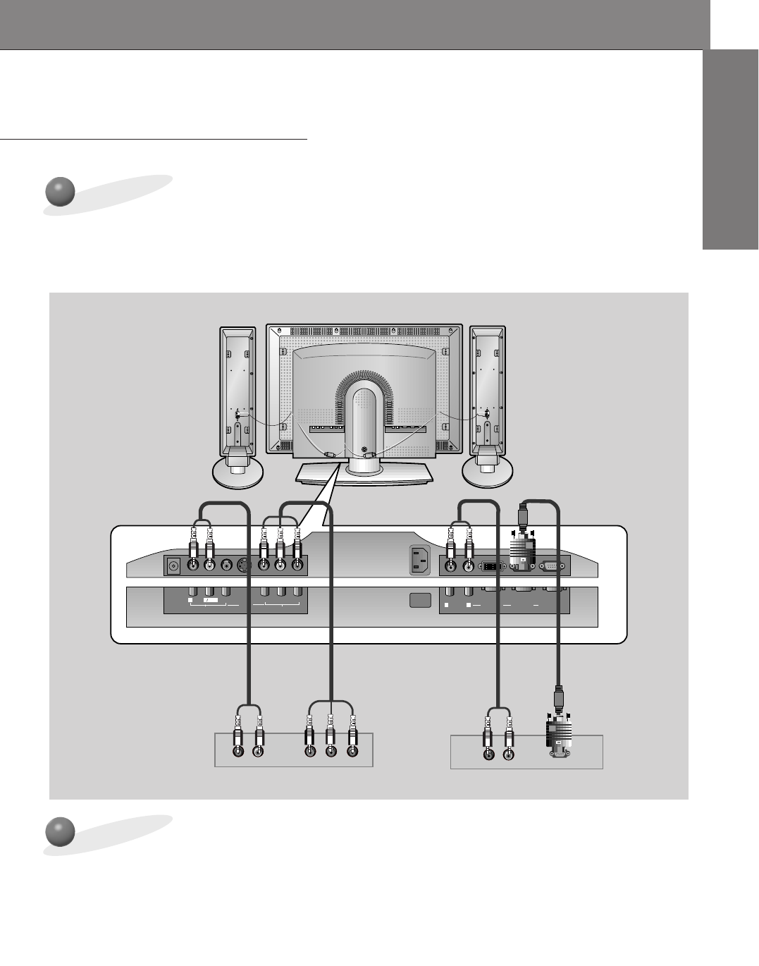
DTV Setup
- To watch digitally broadcast programs, purchase/connect a digital SET-TOP BOX.
How to connect
How to use
Y PBPR
RLMONO
AUDIO VIDEO
S-VIDEO
AV INPUT COMPONENT (DVD/DTV INPUT)
AC INPUT
RL
AUDIO RGB 2 INPUT
(DIGITAL RGB INPUT) RGB 1 INPUT
(PC/DTV INPUT) RS 232C INPUT
(CONTROL/SERVICE)
(R) AUDIO (L)
(R) AUDIO (L) Y P
B R
PDTV OUTPUT
DC OUTPUT
(DC 12V)
• Turn on the digital SET-TOP BOX.
(Refer to the owner’s manual for the digital SET-TOP BOX.)
• Press INPUT SELECT button on the remote control to select COMPONENT or RGB1.
Back panel of a digital SET-TOP BOX
or
• You can use either the Monitor’s COMPONENT (DVD/DTV INPUT) inputs or the single
RGB1(PC/DTV INPUT) for video connections, depending on your Set Top Box connectors.
Then, make the corresponding Audio connections.
•DTV Input is available to 480p, 720p, 1080i mode.
Back panel of the Monitor
24
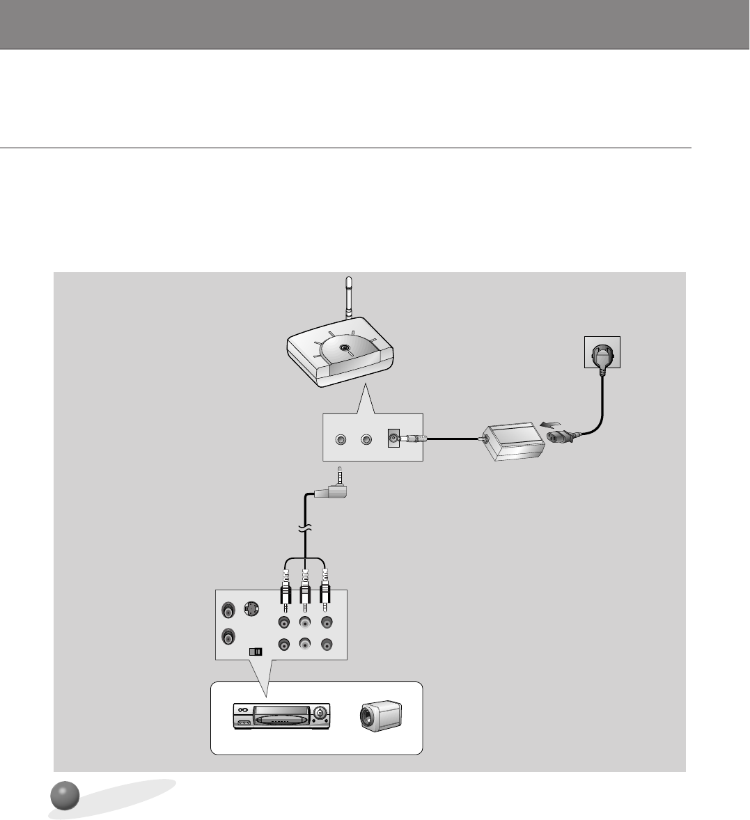
Connecting to a wireless
trasmitter (option)
How to connect
S VIDEO
(R) AUDIO (L) VIDEO
OUT
IN
AV INPUT
AV OUTPUT 12V DC INPUT
CH1 CH2 CH3
CH S/W
CH4CH1 CH2 CH3
CH S/W
CH4
AV INPUT
a.Turn the power button of a transmitter on, and adjust desired channel with channel button and
the Place the wireless AV transmitter toward the wireless receiver.
b.Connect the output ports of the VCR to the AV OUTPUT port of the wireless AV transmitter.
c. Connect the adaptor to the DC input of the wireless AV transmitter .
d.Connect the power plug to the wall outlet socket after connecting the power cord to the adaptor.
•Only adjust this function in some models.
• When connecting the wireless transmitter with external equipments, match the colors of
connecting ports (Video - yellow, Audio(L) - white, Audio(R) -red).
• If you have a mono VCR, connect the audio cable from the VCR to the AV input of the wireless
AV transmitter.
• See the wireless trasmitter-receiver operating guide for installation and connection etc.
Transmitter rear
VCR rear
VCR CAMCORDER
a
b
c
d
25
ENGLISH
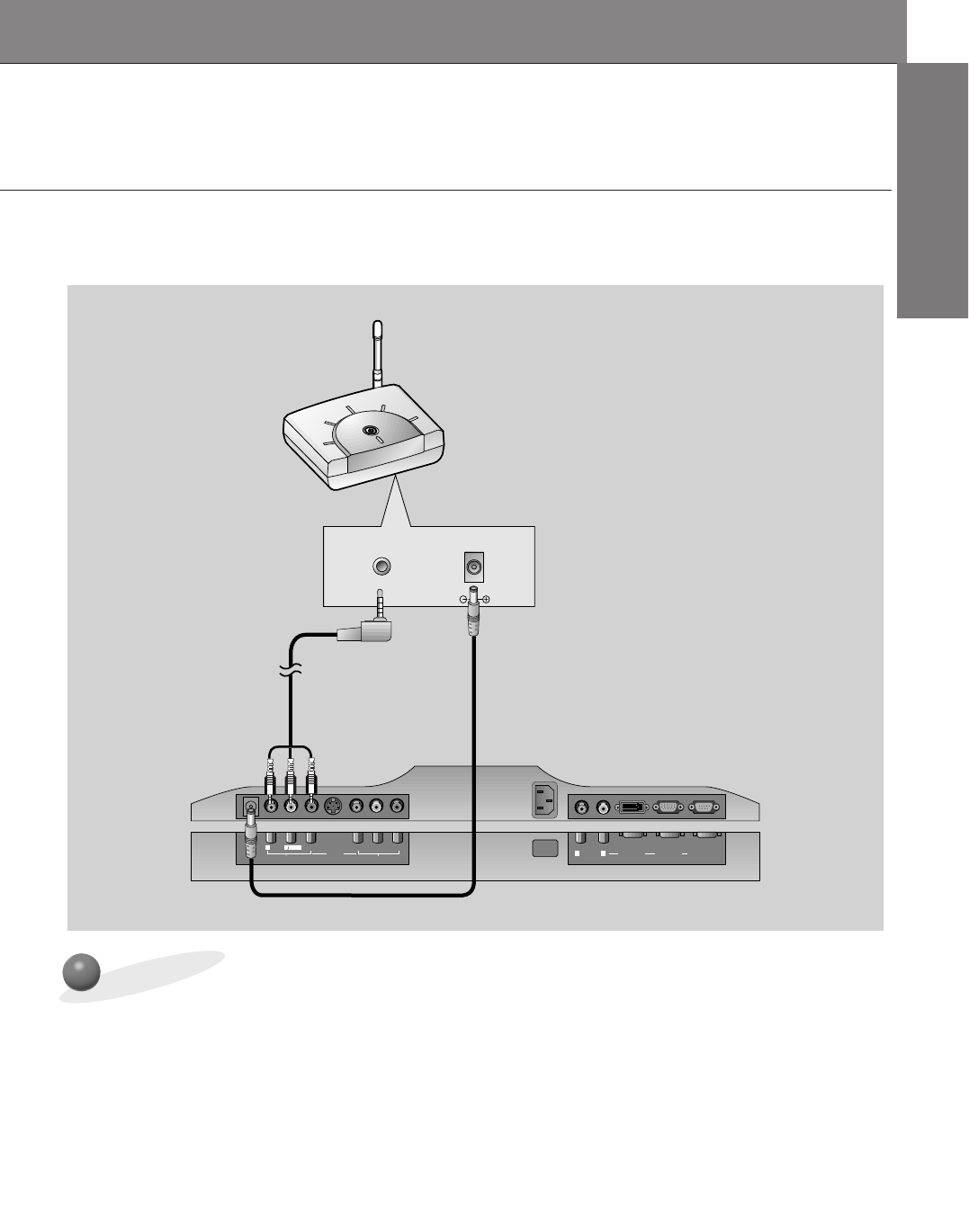
Connecting to a wireless
receiver (option)
How to connect
Y PBPR
RLMONO
AUDIO VIDEO
S-VIDEO
AV INPUT COMPONENT (DVD/DTV INPUT)
AC INPUT
RL
AUDIO RGB 2 INPUT
(DIGITAL RGB INPUT) RGB 1 INPUT
(PC/DTV INPUT) RS 232C INPUT
(CONTROL/SERVICE)
DC OUTPUT
(DC 12V)
12V DC INPUT
CH1 CH2 CH3
CH S/W
CH4
CH1 CH2 CH3
CH S/W
CH4
AV INPUT
a. Turn the power button of a receiver on, and adjust channel number same to the channel num-
ber of a transmitter with the channel button. Place the wireless AV receiver toward the wire-
less transmitter.
b. Connect the AV input ports of the Monitor to the AV INPUT port of the receiver.
c. Connect the DC output of the monitor to DC input of the wireless receiver with DC cable.
•Only adjust this function in some models.
• When connecting the wireless receiver with external equipments, match the colors of con-
necting ports (Video - yellow, Audio(L) - white, Audio(R) -red).
Back panel of the Monitor
a
bc
Receiver rear
26
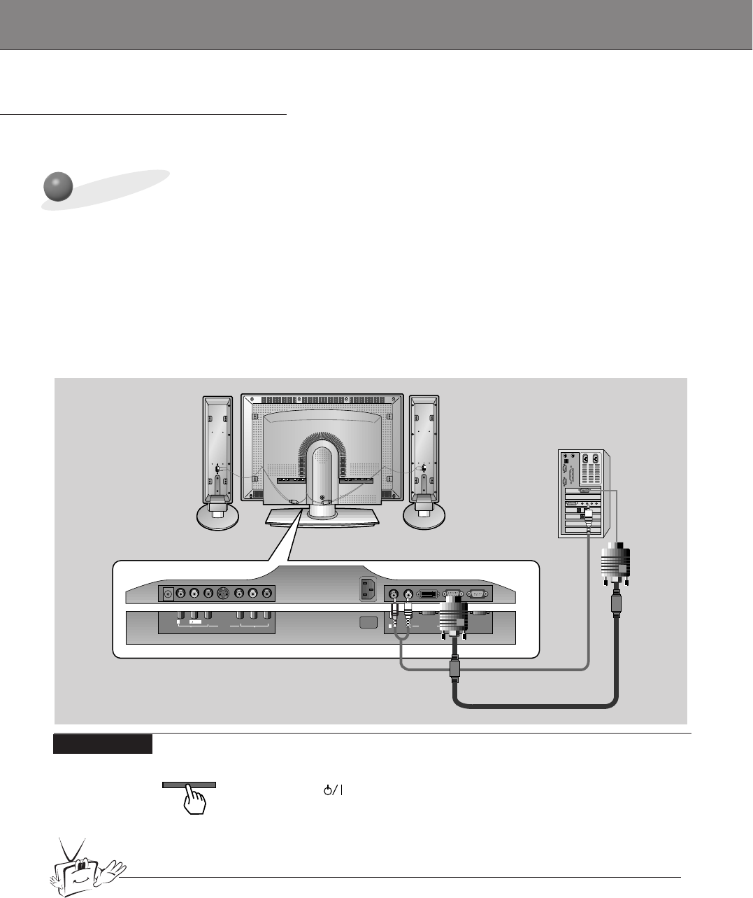
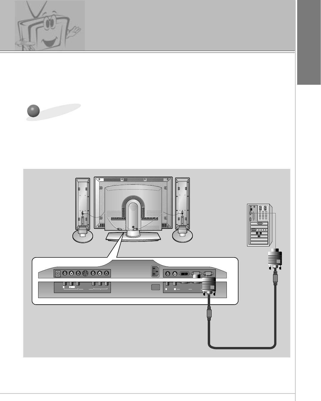
PC Setup
-You can easily connect the Plasma Display to your PC for outstanding image and sound.
On the remote control
How to use
Y PBPR
RLMONO
AUDIO VIDEO
S-VIDEO
AV INPUT COMPONENT (DVD/DTV INPUT)
AC INPUT
RL
AUDIO RGB 2 INPUT
(DIGITAL RGB INPUT) RGB 1 INPUT
(PC/DTV INPUT) RS 232C INPUT
(CONTROL/SERVICE)
L
DC OUTPUT
(DC 12V)
Tips
Back panel of the Monitor
Setup Instructions to Connect a PC to your Monitor
• To setup this monitor in your PC window environ-
ment, select Normal, Standard or Default Monitor.
This monitor does not support Plug and Play func-
tion
• The screen does not display when the resolution is
over UXGA.
• Connect the signal cable from the monitor Output
port on the PC to the RGB1(PC/DTV INPUT) port
on the Monitor.
• Connect the audio cable from the PC to the Audio
ports of the Monitor.
• If your PC computer is equipped with a sound card,
adjust the sound output on the PC.
• Select the display resolution of the PC to
1024X768 for the best picture. This monitor’s reso-
lution is 1280X768.
PC Setup
•First, turn on the PC computer and press the ON/OFF button on the
Monitor to apply power to it. Second, turn on the display by pressing
the button on the Monitor or by pressing the POWER button on
the Monitor’s remote control.
•Use the INPUT SELECT button on the remote control to select the
RGB1 input source.
•Set the resolution output of the PC to SXGA or under (1280 x 1024,
75Hz).
• Avoid keeping a fixed image on the Monitor's screen for a long period of time. The fixed image may
become permanently imprinted on the screen; use a screen saver when possible.
• Change the resolution of PC to displayable mode (Refer to page 27,28) and connect to RGB1 Input
(PC/DTV Input) jacks of the monitor.
INPUT SELECT
27
ENGLISH
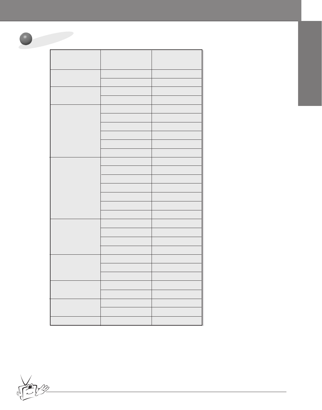
Monitor Image Display Specifications (RGB1)
640x350
720x400
31.468 70.09
37.861 85.08
31.469 70.08
37.927 85.03
31.469 59.94
37.861 72.80
37.500 75.00
43.269 85.00
53.011 100.04
64.062 120.00
35.156 56.25
37.879 60.31
48.077 72.18
46.875
1024x768
1152x864
832x624
1280x960
1280x1024
75.00
53.674 85.06
56.000 90.00
64.016 100.00
48.363 60.00
56.476 70.06
60.023 75.02
68.677 84.99
54.348 60.05
67.500 75.00
77.487 85.05
49.725 74.55
60.000 60.00
75.000 75.00
63.981 60.02
79.976 75.02
Resolution
Horizontal
Frequency (KHz) Vertical
Frequency (Hz)
640x480
800x600
Tips
•Synchronization input form : separate
• Dos mode may not work depending on video card if using a DVI-I cable.
28
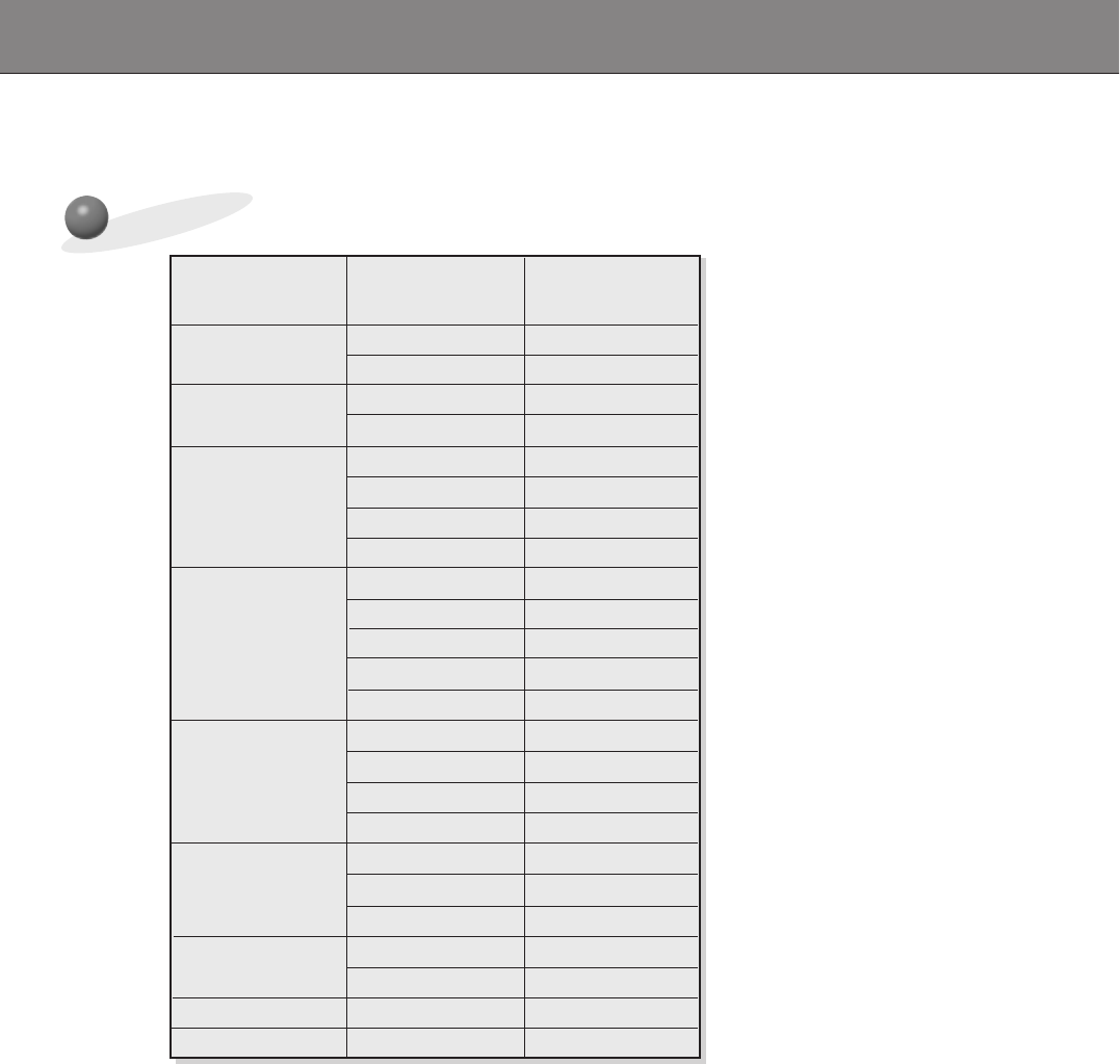
Monitor Image Display Specifications (RGB2)
640x350
720x400
31.468 70.09
37.861 85.08
31.469 70.08
37.927 85.03
31.469 59.94
37.861 72.80
37.500 75.00
43.269 85.00
35.156 56.25
37.879 60.31
48.077 72.18
46.875
1024x768
1152x864
832x624
1280x960
1280x1024
75.00
53.674 85.06
48.363 60.00
56.476 70.06
60.023 75.02
68.677 84.99
54.348 60.05
67.500 75.00
77.487 85.05
49.725 74.55
60.000 60.00
75.000 75.00
63.981 60.02
Resolution
Horizontal
Frequency (KHz) Vertical
Frequency (Hz)
640x480
800x600
29
ENGLISH
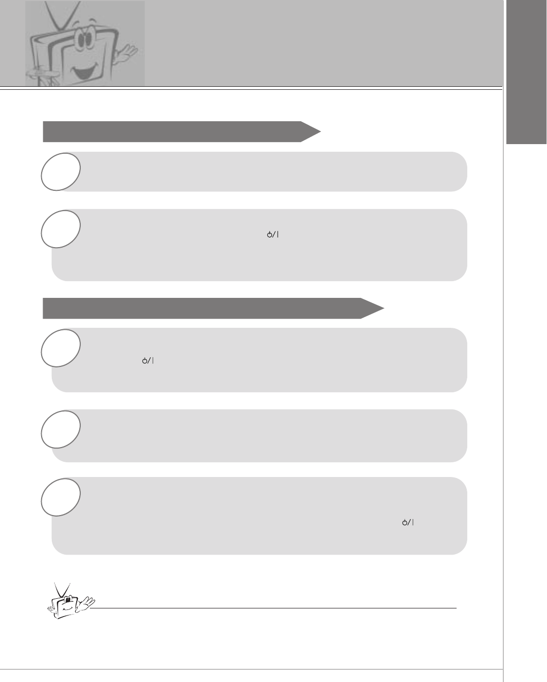
Turning on the Monitor
3
2
1
2
1
- When using the remote control, aim it at the sensor on the Monitor.
Turning on the Monitor just after installation
Turning on the Monitor (power cord is still connected)
Connect power cord correctly.
Press the main ON OFF button on the Monitor. At this moment, the Monitor is
switched to standby mode. Press the or INPUT SELECT button on the
Monitor or press the POWER or INPUT SELECT button on the remote control
and then the Monitor will be turned on.
Press the or INPUT SELECT button on the Monitor or press the POWER
or INPUT SELECT button on the remote control and then the Monitor will be
turned on.
If the Monitor is turned off with the remote control button.
• Press the main ON OFF button on the Monitor to turn on the Monitor.
If the Monitor is turned off with the ON OFF button on the Monitor
• Press the main ON OFF button on the Monitor and then press the or
INPUT SELECT button on the Monitor or press the POWER or INPUT
SELECT button on the remote control and then the Monitor will be turned on.
If the Monitor is turned off with the remote control and also the ON OFF
button on the Monitor
Tips
•Adjusting volume level
The volume(GG) button increases the sound and the volume(FF) button reduces
the level of sound.
30
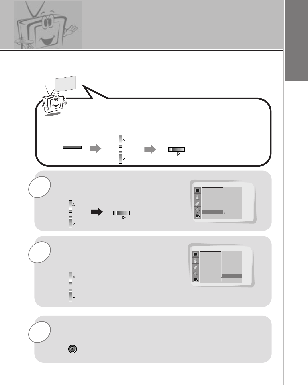
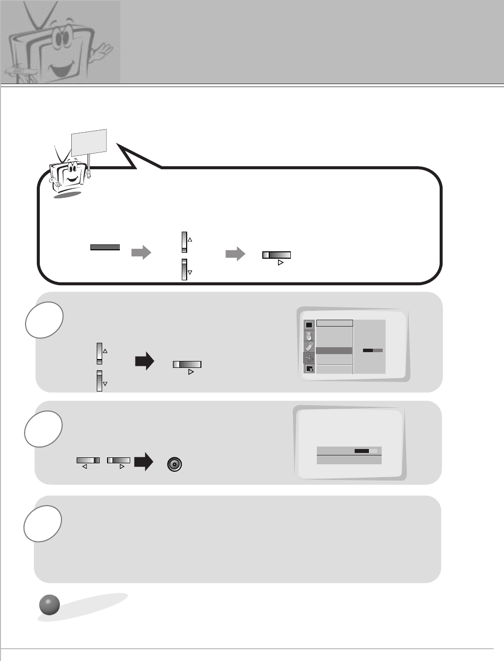
1
3
2
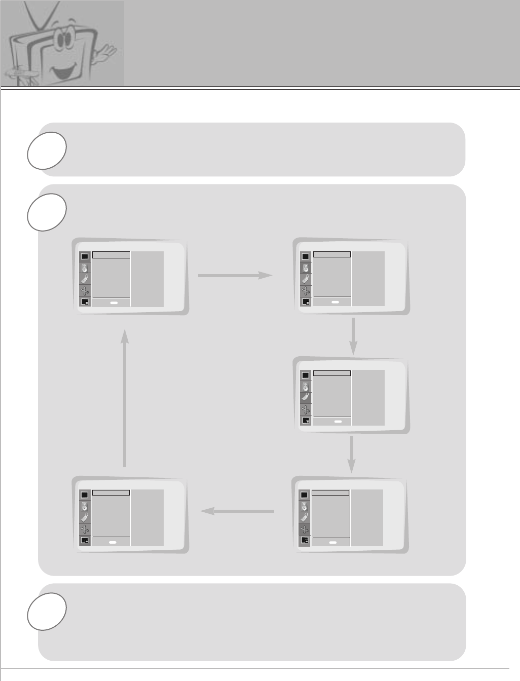
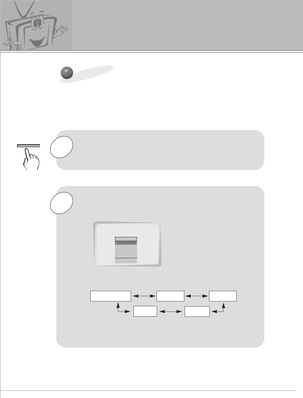
Press the MENU button.
Press the UP/DOWN button.
•Each press will cycle through the menus shown below.
Checking features
Press the VOL ( G) button to select a feature to adjust, and then
press the UP/DOWN buttons to adjust the selected item.
•Press the MENU button to exit.
<Picture adj. menu>
<Sound menu>
<Twin/pip menu>
-Use the remote control to make adjustments.
- Select VIDEO input source.
SOUND
SPECIAL
PICTURE ADJ.TWIN/PIP
PICTURE
APC
CONTRAST
BRIGHTNESS
COLOR
SHARPNESS
TINT
SCREEN
DASP
TREBLE
BASS
BALANCE
LANGUAGE
COLOR TEMP.
R-ADJUST
G-ADJUST
B-ADJUST
SCREEN SAVER
SET ID
AUTO. CONFIG.
ARC(MAIN)
ZOOM IN/OUT
POSITION
CLOCK ADJUST
PHASE ADJUST
RESET
TWIN
PIP
INPUT (MAIN)
INPUT (SUB)
WINDOW SIZE
WINDOW POSITION
WINDOW RESET
D
EMOVE
D
EMOVE
D
E
D
EMOVE
D
EMOVE
<Special menu>
<Picture menu>
menu EXIT EXIT
EXIT
EXITEXIT
menu
menu
menu
menu
MOVE
31
ENGLISH
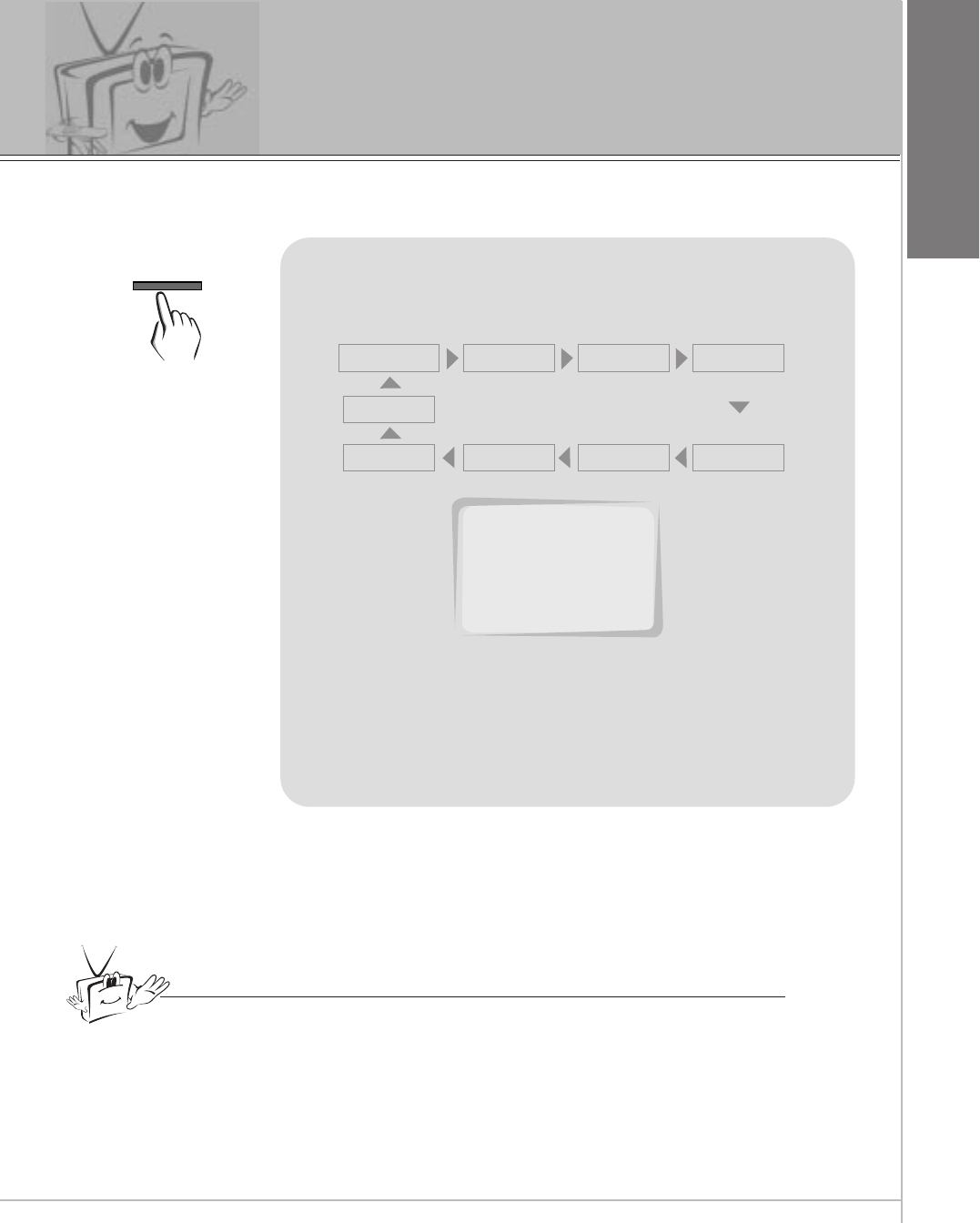
Setting Sleep Timer
Sleep Timer turns the Monitor off after a preset time
Press the SLEEP button to set sleep time.
Each time you press SLEEP button, the next pre-
set setting time is changed as follows:
• To release sleep time setting, press the SLEEP
button repeatedly to select OFF.
OFF 10 20 30
120 180
240
90 60
Tips
• To check remaining sleep time after setting, press the SLEEP or ENTER
button just once.
• If you turn the Monitor off after setting the sleep timer, the setting is erased.
The sleep timer will then have to be set again.
SLEEP: 10
SLEEP
32
2
1
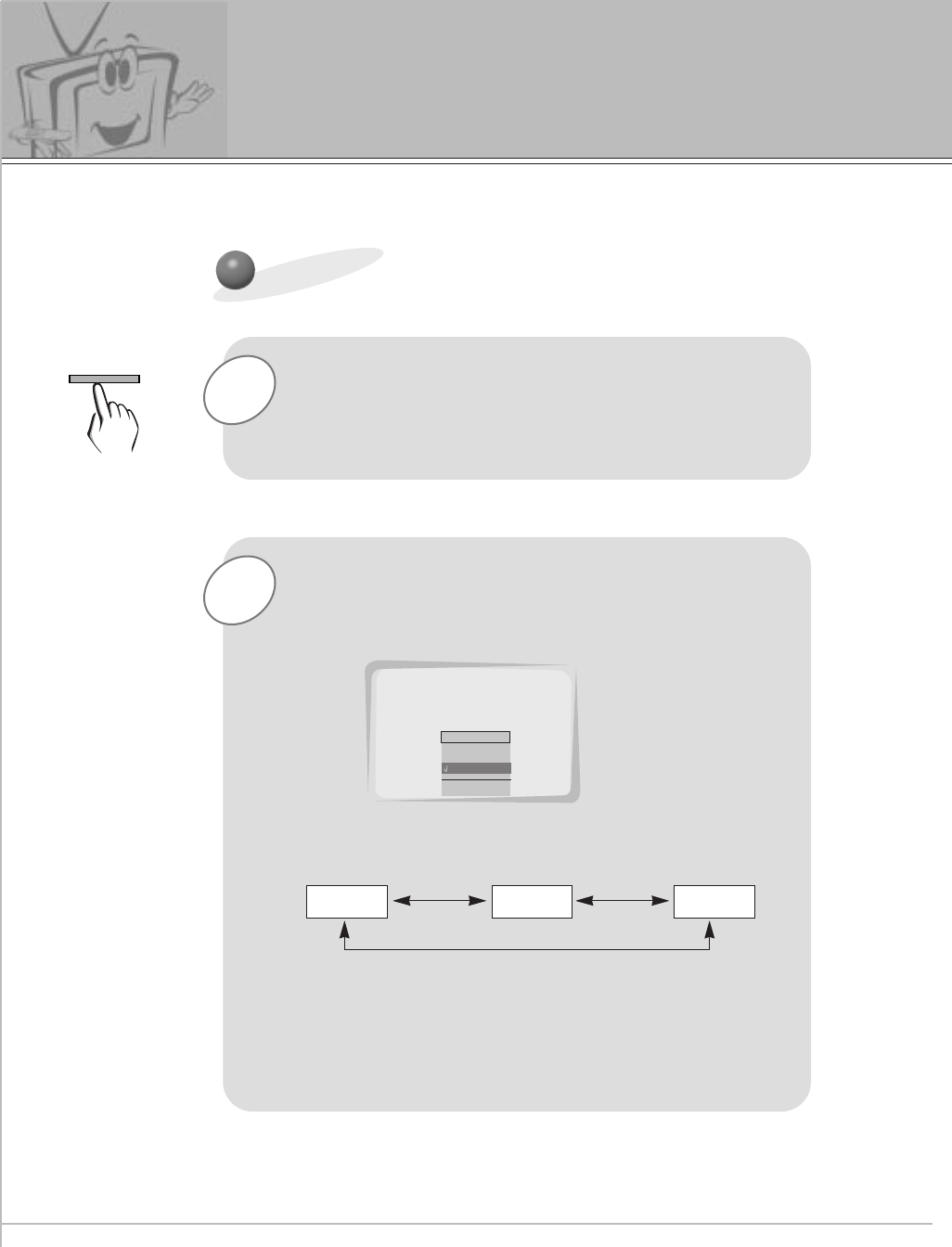
APC (Auto Picture Control)
Press the APC button.
Press the APC or UP/DOWN buttons to select your
desired picture condition.
•Each press of APC button or UP/DOWN buttons changes
the screen display as shown below.
• You can also select CLEAR, SOFT or USER in the
PICTURE menu.
CLEAR SOFT USER
Auto picture control
Use APC to set the Monitor for the best picture appearance
APC
CLEAR
SOFT
USER
APC
D
EADJUST A EXIT
USER
33
ENGLISH
2
1
READY
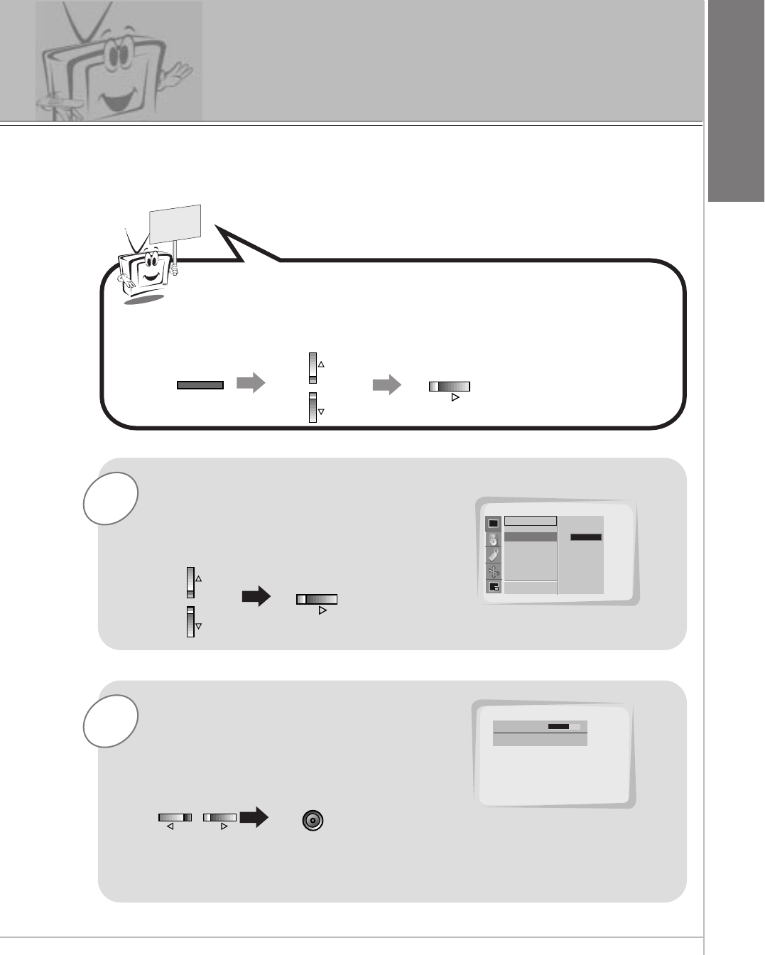
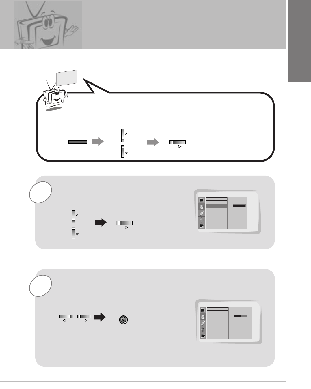
Press the UP/DOWN button to select
CONTRAST and then press the
VOL ( G)button.
•Adjust BRIGHTNESS, COLOR, SHARPNESS and TINT in the same way.
Use the VOL buttons to make appro-
priate adjustments and then press the
ENTER button.
•Press the UP/DOWN buttons to select other
items.
Press the MENU button and then press the UP/DOWN button
to select PICTURE menu.
Press the VOL ( G) button.
Adjusting picture appearance
MENU
VOL
VOL
VOLVOL
PICTURE
D
EMOVE FPREV.
APC
CONTRAST
BRIGHTNESS
COLOR
SHARPNESS
TINT
SCREEN
CONTRAST G100
CONTRAST 80
FG ADJUST D
EMOVE A PREV.
ENTER
34
Auto Sound Control
DASP (Digital Auto Sound Processing)
•This function lets you enjoy the best sound without any manual adjustment
because the Monitor automatically selects the appropriate audio tone levels
based on the program content.
1Press the DASP button.
2Press the DASP or UP/DOWN button to select a
sound setup.
•Each press of DASP or UP/DOWN buttons changes the
screen display as shown below.
• You can also select NORMAL, CINEMA, MUSIC,
SPORTS or USER in the SOUND menu.
NORMAL CINEMA
USER
MUSIC
SPORTS
DASP
NORMAL
CINEMA
MUSIC
SPORTS
USER
DASP
D
EADJUST A EXIT
NORMAL
35
ENGLISH
Adjusting Sound
Manual Settings
1
READY
Press the UP/DOWN button to select
TREBLE and then press the VOL ( G)
button.
Press the MENU button and then press the UP/DOWN button
to select SOUND menu.
Press the VOL ( G) button.
2Use the VOL buttons to make appropriate
adjustments and then press the ENTER
button.
•Press the UP/DOWN buttons to select other items.
MENU
VOL
VOL
VOLVOL ENTER
SOUND
DASP
TREBLE
BASS
BALANCE
D
EMOVE
TREBLE G100
SOUND
DASP
TREBLE
BASS
BALANCE
50
F PREV.
APREV.
•Adjust BASS and BALANCE in the same way.
FGADJUST
36
Selecting language for the menus
3
2
1
READY
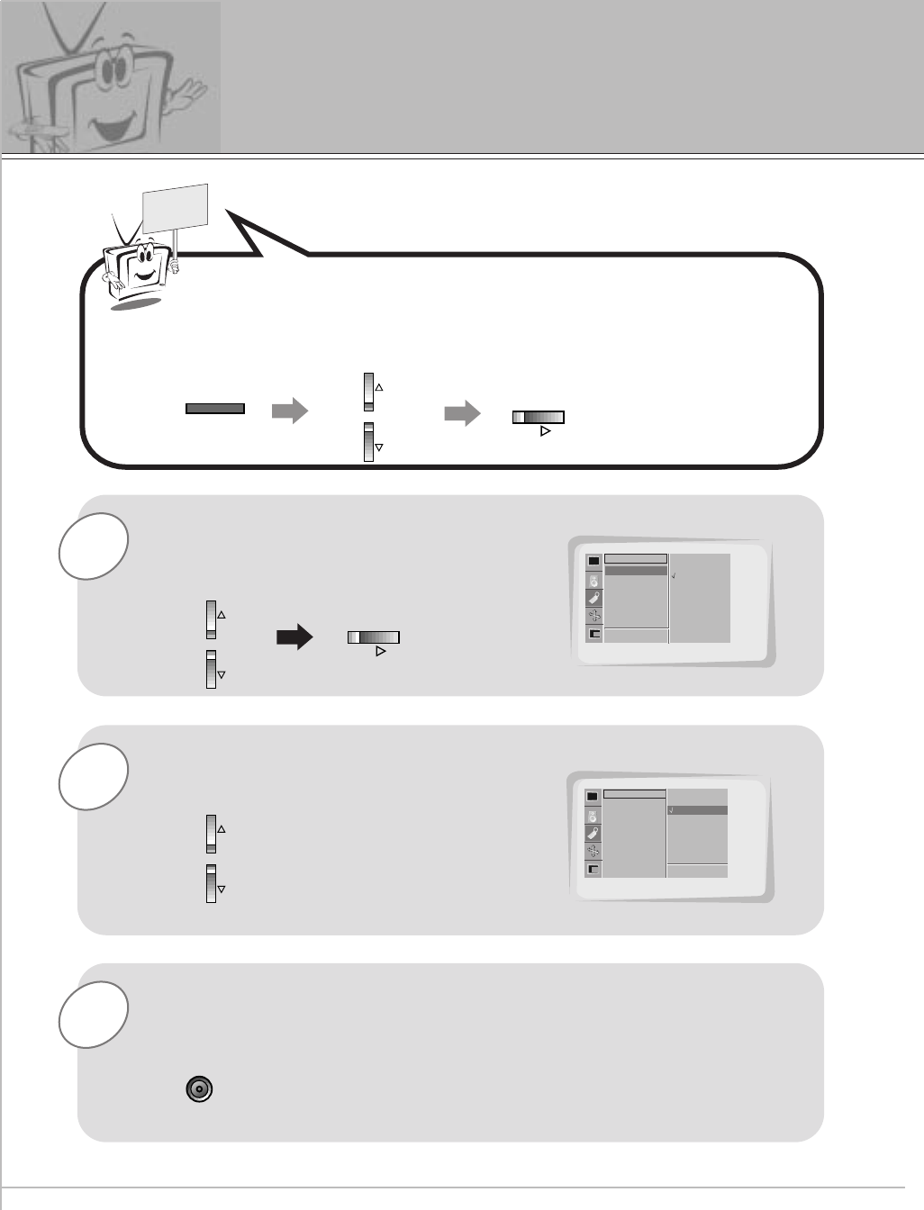
Press the UP/DOWN button to select
LANGUAGE and then press the
VOL ( G) button.
Press the UP/DOWN button to select
the desired language.
Press the ENTER button.
Press the MENU button and then press the UP/DOWN button
to select SPECIAL menu.
Press the VOL ( G) button.
MENU
VOL
VOL
ENTER
LANGUAGE
COLOR TEMP.
R-ADJUST
G-ADJUST
B-ADJUST
SCREEN SAVER
SET ID
SPECIAL
LANGUAGE
¢”
˙–„
ENGLISH
D
EF
MOVE PREV
.
LANGUAGE
COLOR TEMP.
R-ADJUST
G-ADJUST
B-ADJUST
SCREEN SAVER
SET ID
SPECIAL
˙–„
ENGLISH
ENGLISH
MOVE PREV.
D
EA
37
ENGLISH
READY
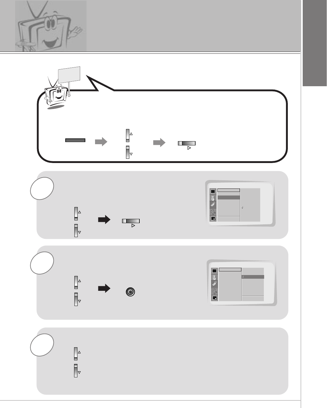
Press the MENU button and then press the UP/DOWN button
to select SPECIAL menu.
Press the VOL ( G) button.
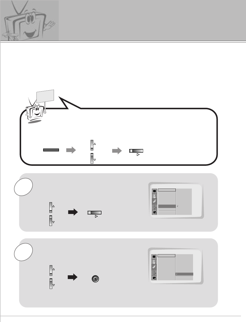
Adjusting color temperature
3
2
1Press the UP/DOWN button to select
COLOR TEMP. and then press the
VOL ( G) button.
Press the UP/DOWN button to select
your desired color temperature and then
press the ENTER button.
Press the UP/DOWN button to select R-ADJUST, G-ADJUST
and B-ADJUST in the same way.
•Press the VOL ( F)button again to move other menu.
MENU
VOL
VOL
ENTER
SPECIAL
LANGUAGE
COLOR TEMP.
R-ADJUST
G-ADJUST
B-ADJUST
SCREEN SAVER
SET ID
D
EMOVE
SPECIAL
LANGUAGE
COLOR TEMP.
R-ADJUST
G-ADJUST
B-ADJUST
SCREEN SAVER
SET ID
D
EMOVE
COLOR TEMP. G
F PREV.
APREV.
NORMAL
COOL
WARM
USER
NORMAL
COOL
WARM
USER
NORMAL
38
Using the Screen Saver function
1
READY
Press the UP/DOWN button to select
SCREEN SAVER and then press the
VOL ( G)button.
2Press the UP/DOWN button to select
ON and then press the ENTER button.
- Prolonged display of a still image may cause a permanent image to be ‘burnt’ on the
screen
- If you select Screen Saver "ON", to prevent the permanent image, the picture moves a
little by the sequence of "Right-Bottom-Left-Up" every 10 minutes.
- "SCREEN SAVER" function will help to prevent the effect of the permanent image but it
is possible to permanently burn the screen with a prolonged still image !
Press the MENU button and then press the UP/DOWN button
to select SPECIAL menu.
Press the VOL ( G) button.
MENU
VOL
VOL
SPECIAL
LANGUAGE
COLOR TEMP.
R-ADJUST
G-ADJUST
B-ADJUST
SCREEN SAVER
SET ID
D
EMOVE
SCREEN SAVERG
FPREV
OFF
ON
SPECIAL
LANGUAGE
COLOR TEMP.
R-ADJUST
G-ADJUST
B-ADJUST
SCREEN SAVER
SET ID
D
EMOVE APREV
OFF
ON
ON
ENTER
•Press the VOL ( F)button again to move other menu.
39
ENGLISH
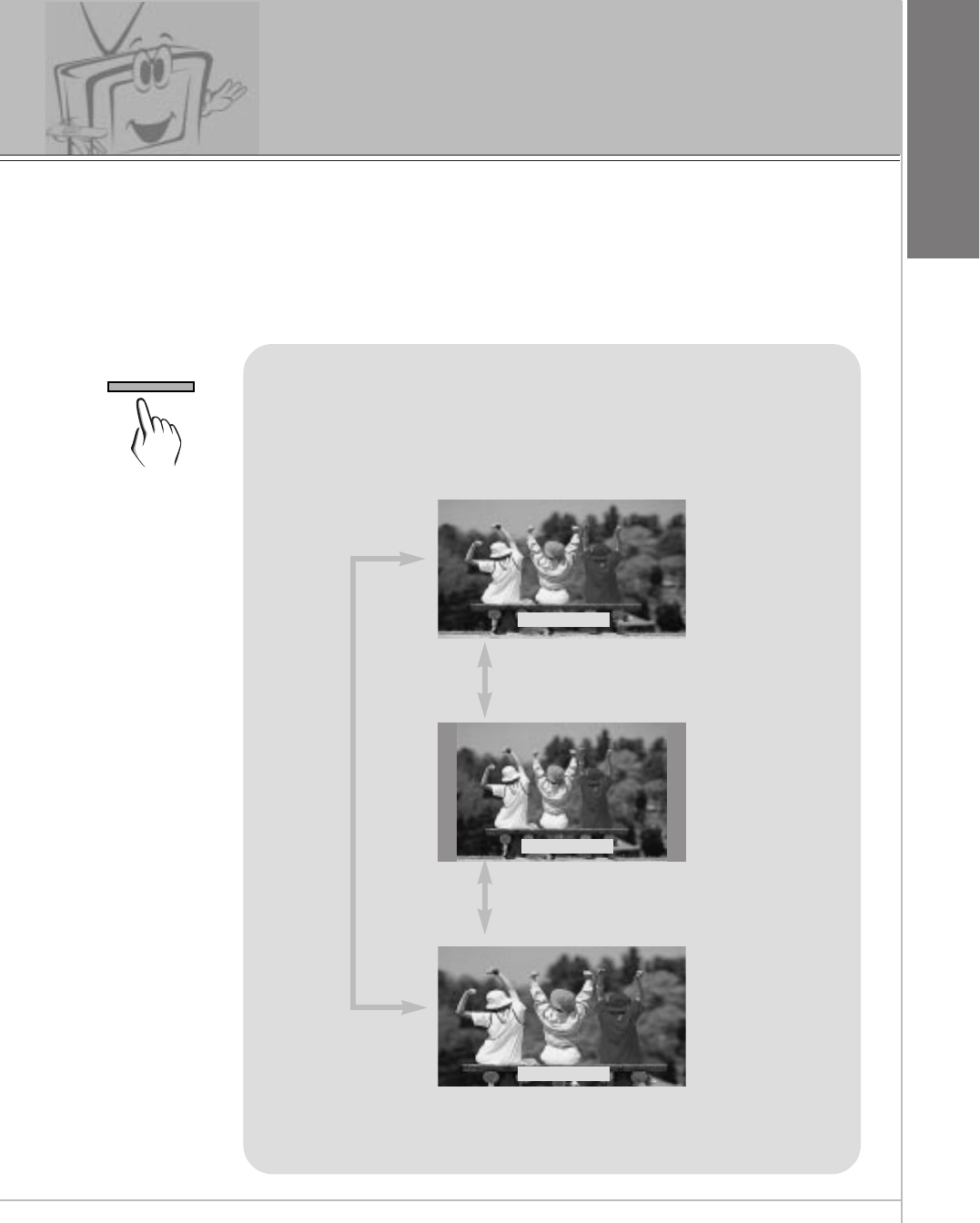
Setting picture format
Press the ARC button to select a desired picture
format.
• You can also select WIDE, NORMAL or ZOOM in the
PICTURE menu.
• Each time you press ARC buttons, you can select
WIDE, NORMAL or ZOOM alternatively.
WIDE
<WIDE>
<NORMAL>
<ZOOM>
NORMAL
ZOOM
- Wide and normal size are possible in RGB1(PC) and RGB2 mode, and Wide, normal and zoom
size are possible in RGB1(DTV) mode.
ARC
40
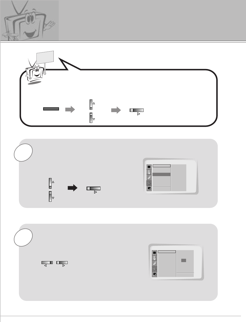
Using the Zoom in/out function
2
1
READY
Press the UP/DOWN button to select
ZOOM IN/OUT and then press the
VOL ( G)button.
• You can zoom in on the image upto 50x.
Press the VOL buttons to adjust desired
zoom in or out.
Press the MENU button and then press the UP/DOWN button
to select PICTURE ADJ. menu.
Press the VOL ( G) button.
MENU
VOL
VOL
VOLVOL
PICTURE ADJ.
AUTO. CONFIG.
ARC(MAIN).
ZOOM IN/OUT
POSITION
CLOCK ADJUST
PHASE ADJUST
RESET
D
EMOVE
ZOOM IN/OUT. G
FPREV
G
ADJUST
0
PICTURE ADJ.
AUTO. CONFIG.
ARC(MAIN).
ZOOM IN/OUT
POSITION
CLOCK ADJUST
PHASE ADJUST
RESET
FG
ADJUST
10
APREV.
41
ENGLISH
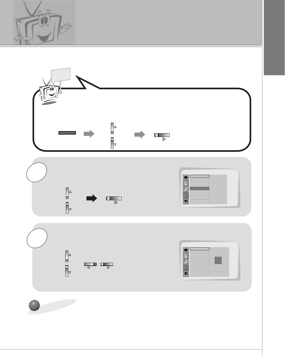
Moving the picture
2
1
READY
Press the UP/DOWN button to select
POSITION and then press the VOL ( G)
button.
Press the VOL buttons or UP/DOWN
button to adjust to the desired picture
position.
Press the MENU button and then press the UP/DOWN button
to select PICTURE ADJ. menu.
Press the VOL ( G) button.
MENU
VOL
VOL
VOLVOL
Initializing
PICTURE ADJ.
AUTO. CONFIG.
ARC(MAIN).
ZOOM IN/OUT
POSITION
CLOCK ADJUST
PHASE ADJUST
RESET
D
EMOVE
POSITION. G
FPREV.
ADJUST
F
D
E
G
PICTURE ADJ.
AUTO. CONFIG.
ARC(MAIN).
ZOOM IN/OUT
POSITION
CLOCK ADJUST
PHASE ADJUST
RESET
ADJUST
APREV.
F
D
E
G
• To initialize the adjusted value, select “RESET” with the UP/DOWN button and then press
the VOL(G) button.
-Adjust the screen with ‘ZOOM IN/OUT’ function to use the ‘POSITION’ function.
42
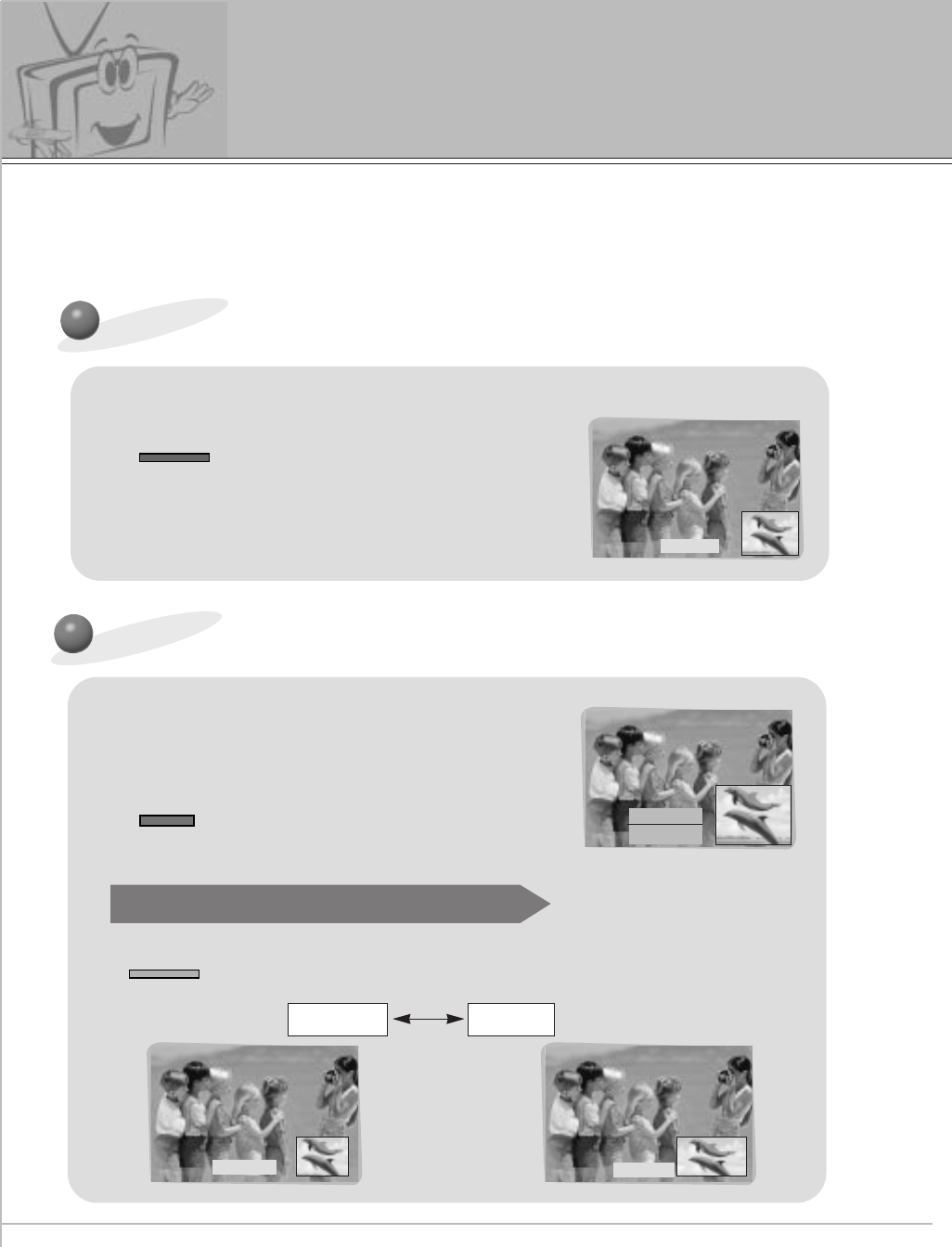
Picture in picture (PIP) function
How to use the PIP
-PIP/TWIN PICTURE will let you view two seperate inputs on your monitor screen at the same time.
-Color of main picture may be different from PIP’s in PIP/TWIN PICTURE.
-When the main picture is RGB1/DTV(more than 480p), the sub picture is Input/S- video/DVD(480i)
and when the main picture is Input / S- video / DVD(480i), the sub picture is RGB1 / DTV(more than
480p) / RGB2.
Press the PIP button.
PIP
Adjusting the size of sub picture
Press the WIN. SIZE button to select
the size of sub picture.
WIN.SIZE
FGADJ. A EXIT
Watching sub picture as 4:3 or 16:9
PIP ARC
•It you press the PIP button again, the function is off.
• Press VOL(F, G) button to adjust desired size.
•WIN. SIZE doesn’t work when there is no signal in sub-picture.
Press the PIP ARC button in PIP.
•Each time you press PIP ARC button, you can change
the pip size.
NORMAL WIDE
WINDOW SIZE
WIDE
NORMAL
PIP : ON
43
ENGLISH
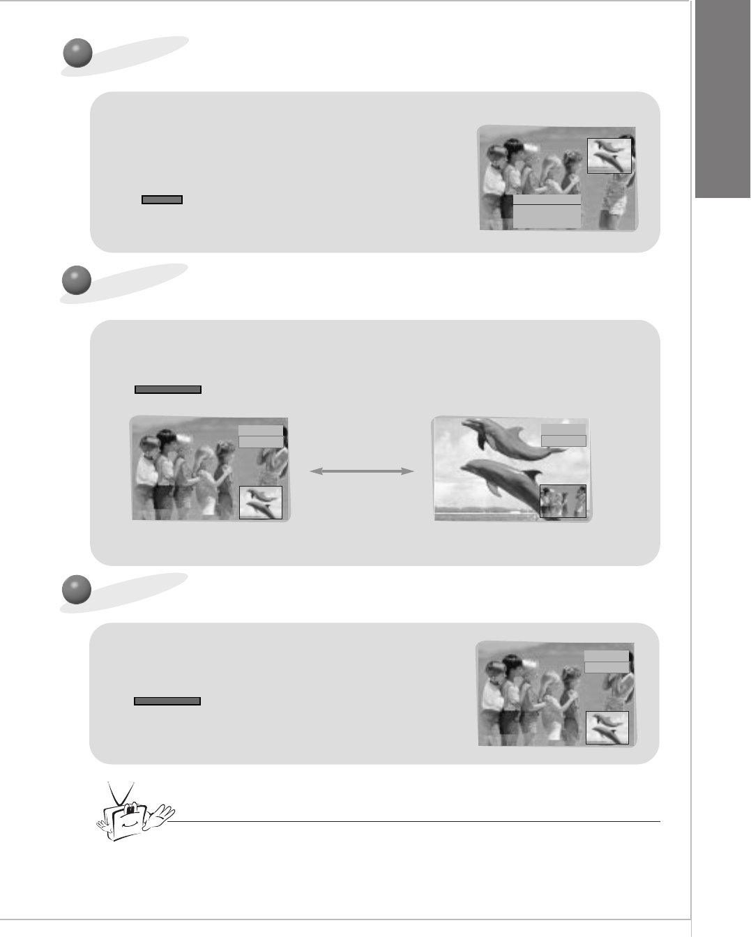
WINDOW POS.
F
D
E
GADJ. A EXIT
Moving the sub picture
Press the WIN. POSITION button in PIP.
WIN.POSITION
•Press the VOL(F, G) button and UP/DOWN button
to adjust the position.
Change the main picture and the sub picture
Press the PIP SWAP button in PIP.
SWAP
RGB1
VIDEO
VIDEO
RGB1
RGB1
VIDEO
How to connect external control equipment
Press the PIP INPUT button in PIP.
SUB INPUT
Tips
• You can select WINDOW SIZE, WINDOW POSITION, PIP INPUT in the
TWIN/PIP menu.
44
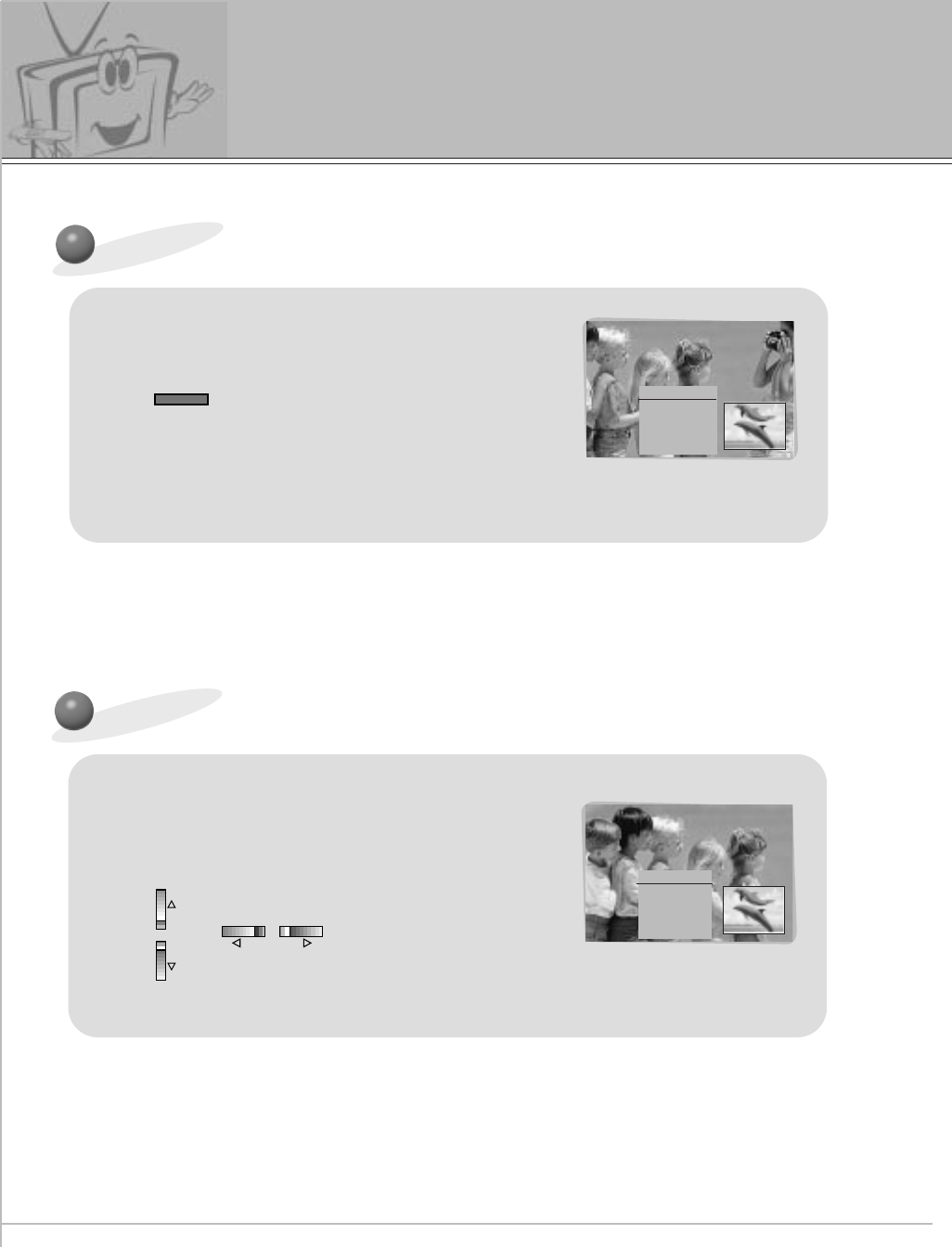
How to connect external control equipment
Press the ZOOM+ button in PIP mode.
ZOOM+
•Enlarge the picture with ZOOM+ button.
‘ZOOM’ is possible to 50.
• Press the ZOOM- button to reduce the zoom effect.
ZOOM 25
F
D
E
G
A
POS.ADJ.
EXIT
Moving the enlarged picture
Press the VOL (F, G)button or
UP/DOWN button to adjust the position
of main picture.
•When the ‘ZOOM’ is ‘0’ moving position.
ZOOM 25
F
D
E
G
A
POS.ADJ.
EXIT
VOLVOL
Zoom in/out main picture
45
ENGLISH
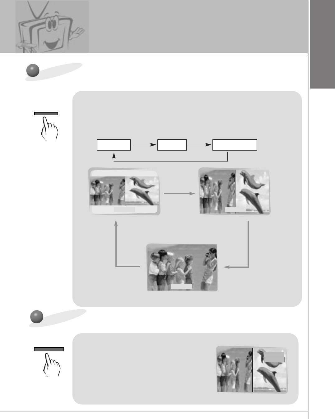
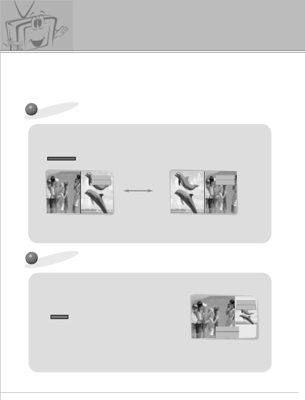
How to use twin picture
TWIN PICTURE
SUB INPUT
Press the TWIN PICTURE button to
select desired twin picture.
TWIN1 TWIN2 TWIN OFF
Input select of the sub picture
VIDEO
RGB1
Press the SUB INPUT button to select
the input select of sub menu.
•When the main picture is RGB1/DTV(more than
480p), the sub picture is Input/S- video/DVD(480i)
and when the main picture is Input / S- video /
DVD(480i), the sub picture is RGB1 / DTV(more
than 480p) / RGB2.
TWIN 1 TWIN 2
TWIN OFF
Twin picture function
•Each time you press TWIN PICTURE buttons, you can
select TWIN1, TWIN2 or TWIN OFF alternatively.
46
VIDEO
RGB1
Changing the picture of main and sub picture
Press the SWAP button in twin picture mode.
SWAP
RGB1
VIDEO
VIDEO
RGB1
Size adjusting sub picture
Press the WIN. SIZE button to select size of
sub picture in the twin picture.
WIN.SIZE
• Press VOL(F, G) button to adjust desired size.
•WINDOW POSITION function doesn’t work in the twin picture mode.
•WINDOW SIZE function doesn’t work when there is no signal of main/sub picture.
FGADJ. A EXIT
WINDOW SIZE
Twin picture function
-PIP/TWIN PICTURE let you view different inputs on your monitor screen at the same time.
-Color of main picture may be different from PIP’s in PIP/TWIN PICTURE.
-When the main picture is RGB1/DTV(more than 480p), the sub picture is Input/S- video/DVD(480i)
and when the main picture is Input / S- video / DVD(480i), the sub picture is RGB1 / DTV(more than
480p) / RGB2.
47
ENGLISH
3
2
1
READY
Use the UP/DOWN button to select
SCREEN and then press the
VOL ( G) button.
Use the UP/DOWN buttons to select
TV or VCR.
Press the ENTER button to exit.
Press the MENU button and then press the UP/DOWN button
to select PICTURE menu.
Press the VOL ( G) button.
Using the screen options
- This function works only in the video mode and S-video mode.
MENU
VOL
VOL
ENTER
PICTURE
APC
CONTRAST
BRIGHTNESS
COLOR
SHARPNESS
TINT
SCREEN
D
EMOVE
SCREEN G
VCR
TV
PICTURE
APC
CONTRAST
BRIGHTNESS
COLOR
SHARPNESS
TINT
SCREEN
D
EMOVE APREV
VCR
TV
TV
FPREV
48
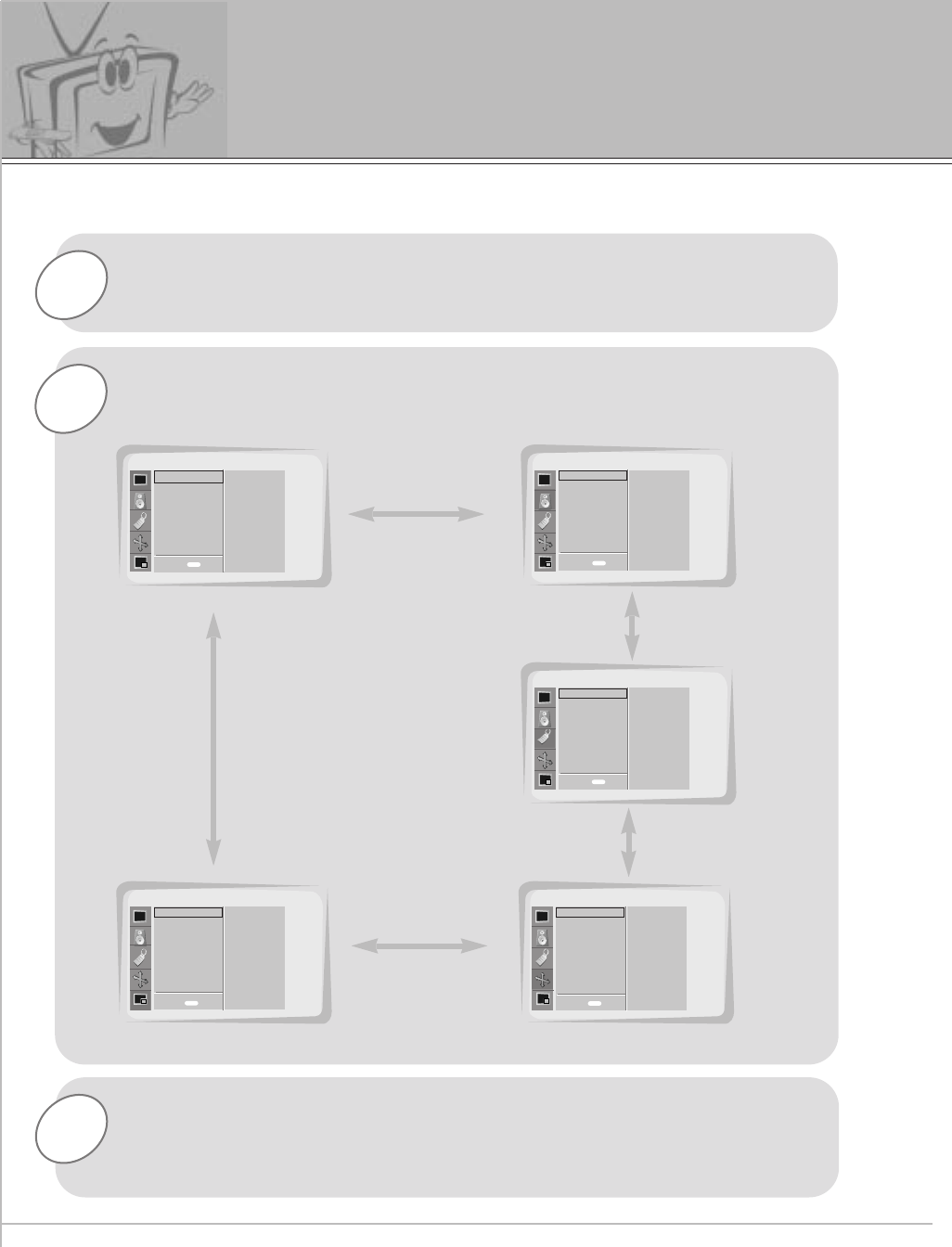
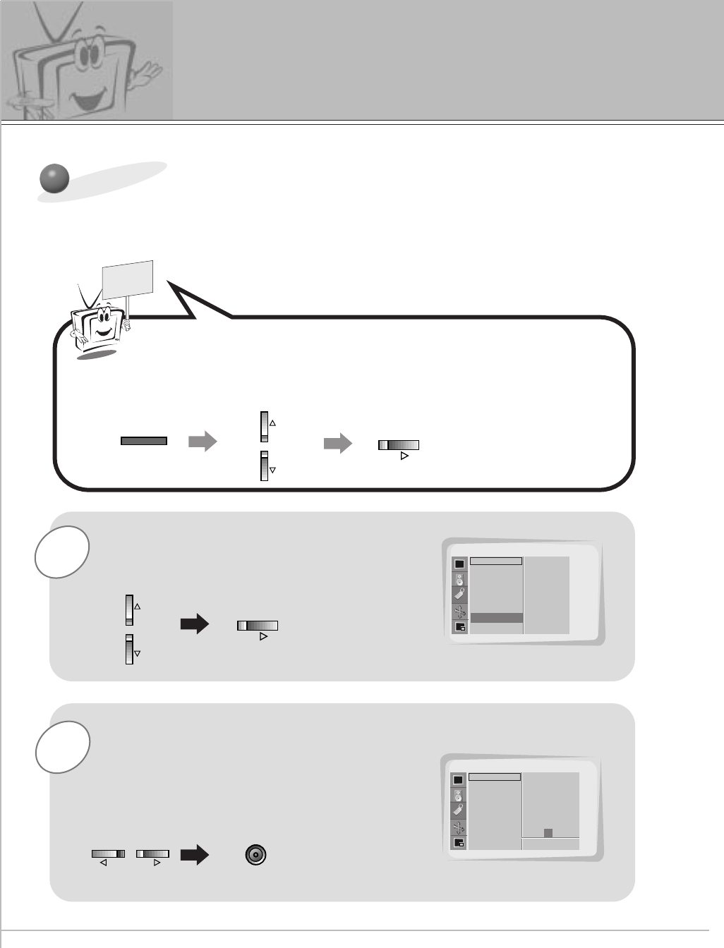
1
3
Press the MENU button.
Press the VOL ( G) button to select a feature to adjust, and then
press the UP/DOWN buttons to adjust the selected item.
•Press the MENU button to exit.
-Use the remote control to make adjustments.
- Select RGB 1 input source.
PC Mode Feature Check
2Press the UP/DOWN button.
•Each press will cycle through the menus shown below.
<Picture adj. menu>
<Sound menu>
<Twin/pip menu>
SOUND
SPECIAL
PICTURE ADJ.TWIN/PIP
PICTURE
APC
CONTRAST
BRIGHTNESS
COLOR
SHARPNESS
TINT
SCREEN
DASP
TREBLE
BASS
BALANCE
LANGUAGE
COLOR TEMP.
R-ADJUST
G-ADJUST
B-ADJUST
SCREEN SAVER
SET ID
AUTO. CONFIG.
ARC(MAIN).
ZOOM IN/OUT
POSITION
CLOCK ADJUST
PHASE ADJUST
RESET
TWIN
PIP
INPUT(MAIN)
INPUT(SUB)
WINDOW SIZE
WINDOW POSITION
WINDOW RESET
D
EMOVE D
EMOVE
D
EMOVE
D
EMOVE
D
EMOVE
<Special menu>
<Picture menu>
menu EXIT EXIT
EXIT
EXITEXIT
menu
menu
menu
menu
49
ENGLISH
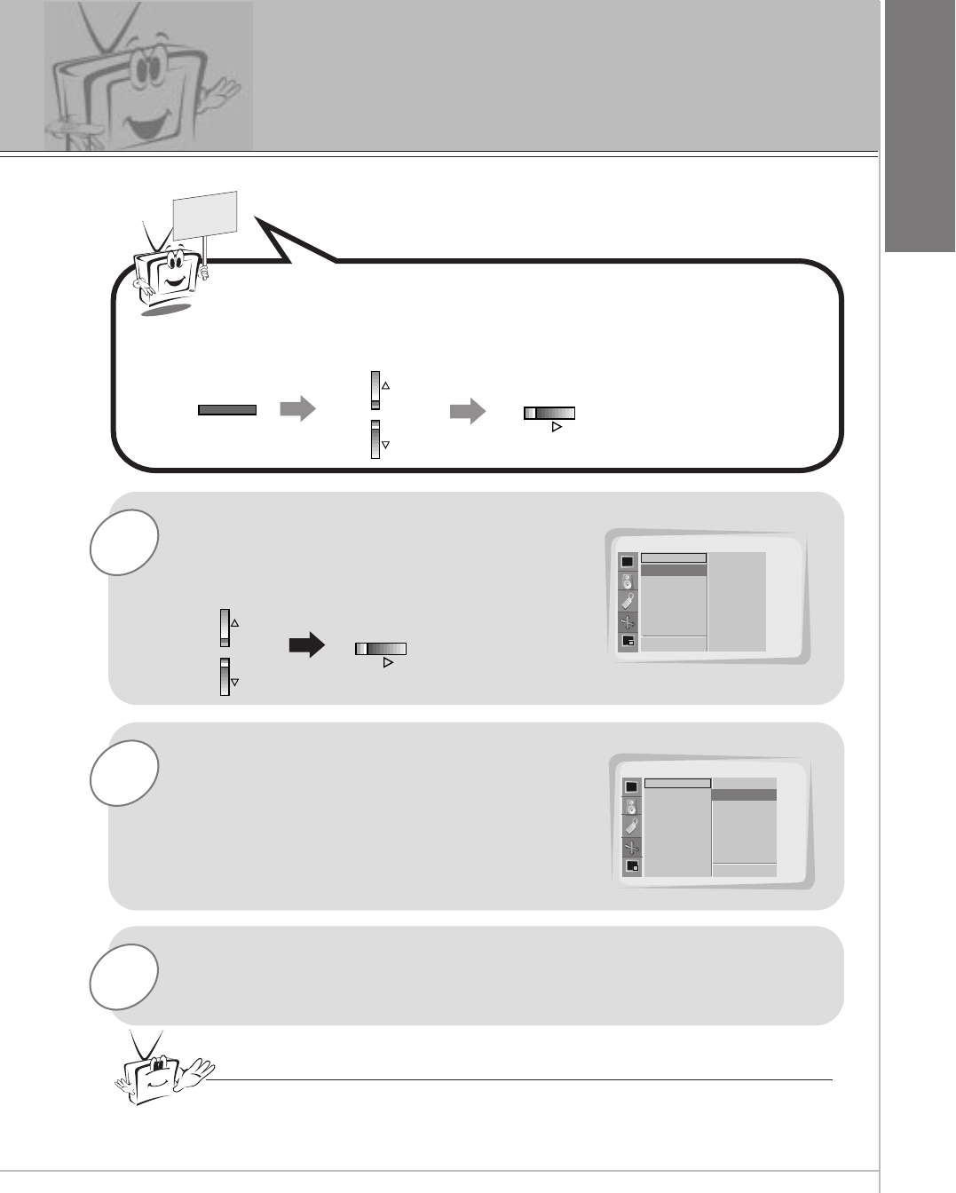
PC Mode Adjustment
2
1
READY
Use the UP/DOWN button to select
AUTO CONFIG. and then press the
VOL ( G) button.
When AUTO CONFIG. has finished,
‘OK’will be shown on screen.
Press the MENU button and then press the UP/DOWN button
to select PICTURE ADJ. menu.
Press the VOL ( G) button.
MENU
VOL
VOL
PICTURE ADJ.
AUTO. CONFIG.
ARC(MAIN).
ZOOM IN/OUT
POSITION
CLOCK ADJUST
PHASE ADJUST
RESET
D
EMOVE
AUTO CONFIG. G
FPREV
TO SET
PICTURE ADJ.
AUTO. CONFIG.
ARC(MAIN).
ZOOM IN/OUT
POSITION
CLOCK ADJUST
PHASE ADJUST
RESET
OK
3If the picture needed to be adjusted a little bit more after auto
adjustment, you can manually adjust the CLOCK ADJUST and
PHASE ADJUST adjustment.
Tips
•The picture may appear strange while auto adjustment is taking place but that
is normal during. This process of searching for the best picture format.
- This function works only in the RGB1 mode.
50
2
1
READY
Use the UP/DOWN button to select
CLOCK ADJUST and then press the
VOL ( G) button.
Use the VOL buttons adjust clock and
then press the ENTER button.
Press the MENU button and then press the UP/DOWN button
to select PICTURE ADJ. menu.
Press the VOL ( G) button.
PC Mode Adjustment
MENU
VOL
VOL
VOLVOL
PICTURE ADJ.
D
EMOVE F PREV
AUTO. CONFIG.
ARC(MAIN).
ZOOM IN/OUT
POSITION
CLOCK ADJUST
PHASE ADJUST
RESET
CLOCK ADJUST G0
CLOCK ADJ. +25
FG ADJUST D
EMOVE APREV.
-Horizontal/Vertical position and CLOCK/PHASE adjustment work in RGB1(PC mode) and
Horizontal/Vertical position only work in RGB(DTV mode-480p,720p,1080i).
ENTER
3Adjust PHASE ADJUST in the same way.
•The adjustment range of CLOCK ADJUST is -50 ~ +50.
• The adjustment range of PHASE ADJUST is 0 ~ 31. (Based on the input
mode, the adjustment range of CLOCK ADJUST/PHASE ADJUST may
change.)
•Based on the input signal, the position of the picture may not change even
though you have adjusted the CLOCK or PHASE position with this function.
Initializing
• To initialize the adjusted value, select “RESET” with the UP/DOWN button and then press
the VOL(G) button.
51
ENGLISH
-Connect the RS-232C input jack to a PC and control the Monitor’s functions (such as ON/OFF, INPUT
SELECT, MUTE) externally.
Y PBPR
RLMONO
AUDIO VIDEO
S-VIDEO
AV INPUT COMPONENT (DVD/DTV INPUT)
AC INPUT
RL
AUDIO RGB 2 INPUT
(DIGITAL RGB INPUT) RGB 1 INPUT
(PC/DTV INPUT) RS 232C INPUT
(CONTROL/SERVICE)
DC OUTPUT
(DC 12V)
Monitor Rear Connections Panel
• Connect the RS-232C (serial connector) input jack with the rear of moniter’s RS-232C
input jack.
• RS-232C connection cables are not supplied with the Monitor.
How to connect external control equipment
External Control Device Setup
52
1Use the UP/DOWN buttons to select SET ID
and then press the VOL ( G) button.
•Use this function to specify a monitor ID number.
SET ID
READY
Press the MENU button and then press the UP/DOWN
button to select SPECIAL menu.
Press the VOL ( G) button.
2Use the VOL button to adjust SET ID to
choose the desired monitor ID number and
then press the ENTER button.
•The adjustment range of SET ID is 1 ~ 99.
External Control Device Setup
MENU
VOL
VOL
VOLVOL ENTER
SPECIAL
LANGUAGE
COLOR TEMP.
R-ADJUST
G-ADJUST
B-ADJUST
SCREEN SAVER
SET ID
D
EMOVE
SET ID G
F PREV
1
SPECIAL
LANGUAGE
COLOR TEMP.
R-ADJUST
G-ADJUST
B-ADJUST
SCREEN SAVER
SET ID
APREV.
1
FG ADJUST
53
ENGLISH
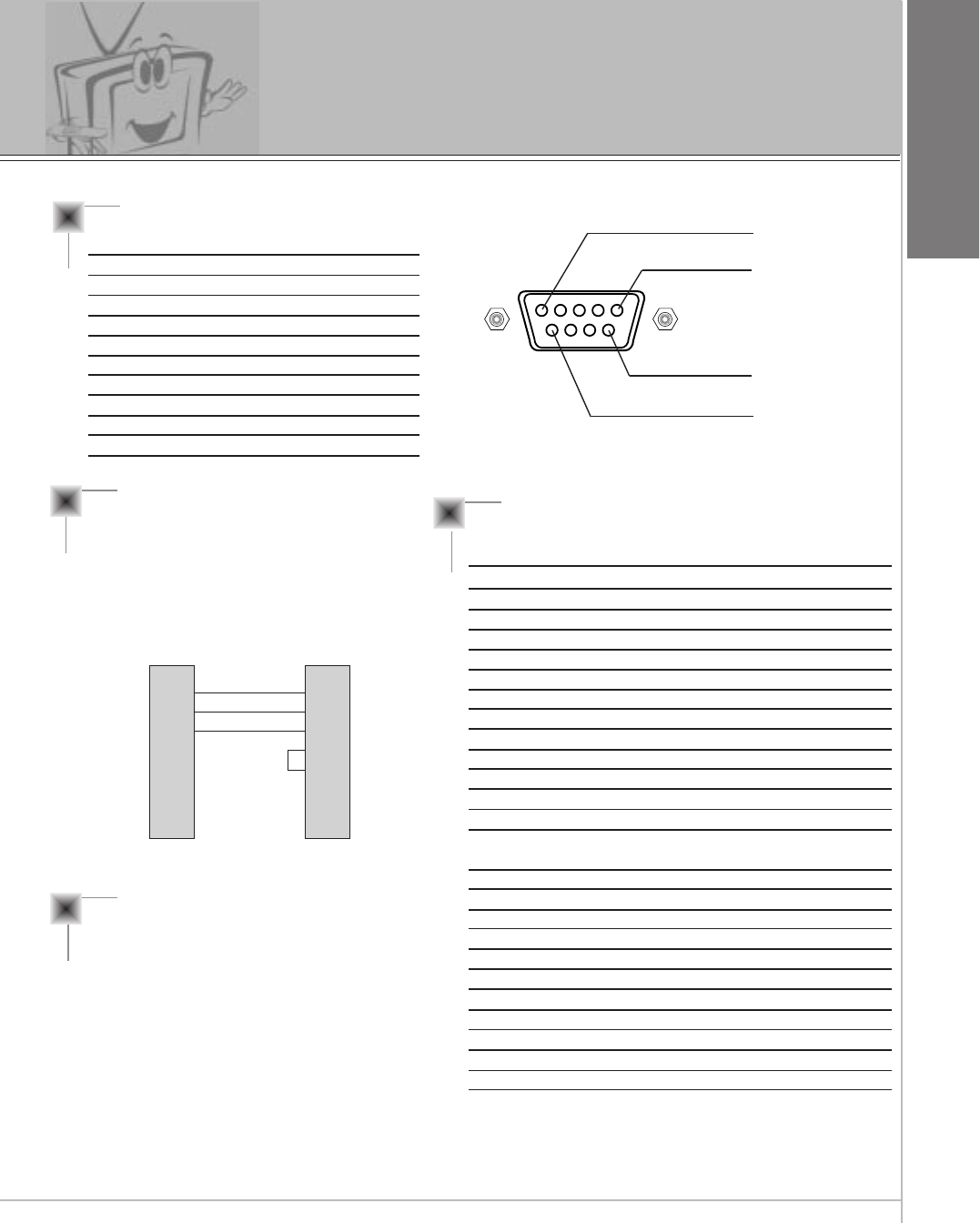
External Control Device Setup
Type of connector : D-Sub 9-pin male
No. Pin name
1 No connection
2 RXD (Receive data)
3 TXD (Transmit data)
4 DTR (DTE side ready)
5 GND
6 DSR (DCE side ready)
7 RTS (Ready to send)
8 CTS (Clear to send)
9 No Connection
1
5
6
9
RS-232C configurations
2
3
5
4
6
7
8
RXD
TXD
GND
DTR
DSR
RTS
CTS
TXD
RXD
GND
DTR
DSR
RTS
CTS
PC
3-wire configuration
(Not standard)
DB 9
3
2
5
4
6
7
8
LCD
DB 9
Communication Parameters
•Baud rate : 115200bps (UART)
•Data length : 8 bits
•Parity : None
•Stop bit : 1 bit
•Communication code : ASCII code
* Use the Crossed (reverse) cable.
-The RS-232C input jack is used to control the Monitor’s functions using an external control device.
NAME Command Command DATA
01. Power k a 0 ~ 1
02. Input Select k b 0 ~ 4
03. Aspect Ratio k c 0 ~ 2
04. Screen mute k d 0 ~ 1
05. Volume mute k e 0 ~ 1
06. Volume control k f 0 ~ 64
07. Contrast k g 0 ~ 64
08. Brightness k h 0 ~ 64
09. Color k i 0 ~ 64
10. Tint k j 0 ~ 64
11. Sharpness k k 0 ~ 64
12. OSD select k l 0 ~ 1
13. remote control k m 0 ~ 1
lock mode
14. PIP select k n 0 ~ 3
15. PIP size k o 0 ~ 1
16. PIP position k q 0 ~ 3
17. Treble k r 0 ~ 64
18. Bass k s 0 ~ 64
19. Balance k t 0 ~ 64
20. Color temperature k u 0 ~ 3
21. R adjust k v 0 ~ 64
22. G adjust k w 0 ~ 64
23. B adjust k $ 0 ~ 64
24. Sub picture input select k y 0 ~ 2
Command Reference List
54
Transmission
* [Command1] : To classify factory-adjustment mode
or user adjustment mode.
* [Command2] : To control LCD set.
* [Set ID] : You can adjust the set ID to choose
desired monitor ID number in special
menu. Adjustment range is 1 ~ 99.
When selecting Set ID ‘0’, every con
nected LCD set is controlled.
select ‘0’, factory adjustment.
(* Transmit as Hexadecimal code.)
* [DATA] : To transmit command data.
Transmit ‘FF’ data to read status of
command.
* [Cr] : Carriage Return
ASCII code ‘0x0D’
* [ ] : Added to classify command, set ID
and DATA.
* [Set ID], [Data] : Input command with 2byte.
[Command1][Command2][ ][Set ID][ ][Data][Cr]
OK Acknowledgement
* The Monitor transmits ACK (acknowledgement) based
on this format when receiving normal data. At this
time, if the data is data read mode, it indicates present
status data. If the data is data write mode, it returns
the data of the PC computer.
[Command2][ ][Set ID][ ][OK][Data][x]
Error Acknowledgement
* The Monitor transmits ACK (acknowledgement) based
on this format when receiving abnormal data from
non-viable functions or communication errors.
* Data : [01] : illegal code (This command is not supported.)
[02] : not support function (This function doesn’t work.)
[03] : wait more time (Try again a few minute later.)
[Command2][ ][Set ID][ ][NG][Data][x]
Transmission / Receiving Protocol
01. Power (Command:p)
GTo control Power On/Off of the Monitor.
Transmission
Data 0 : Power Off
1 : Power On
[k][a][ ][Set ID][ ][Data][Cr]
Acknowledgement
Data 0 : Power Off
1 : Power On
[a][ ][Set ID][ ][OK][Data][x]
GTo show Power On/Off.
Transmission
[k][a][ ][Set ID][ ][FF][Cr]
Acknowledgement
Data 0 : Power Off
1 : Power On
* In like manner, if other functions transmit ‘FF’ data
based on this format, Acknowledgement data feed
back presents status about each function.
[a][ ][Set ID][ ][OK][data][x]
02. Input select (Command:b)
GTo select input source for the Monitor.
You can also select an input source using the INPUT
SELECT button on the Monitor's remote control.
Transmission
Data 0 : RGB1 4 : RGB2
1 : Component
2 : Video
3 : S-Video
[k][b][ ][Set ID][ ][Data][Cr]
Acknowledgement
Data 0 : RGB1 4 : RGB2
1 : Component
2 : Video
3 : S-Video
[b][ ][Set ID][ ][OK][Data][x]
External Control Device Setup
55
ENGLISH
06. Volume control (Command:f)
GTo adjust volume.
You can also adjust volume with the VOL buttons on
remote control.
Transmission
Data Min : 0 ~ Max : 64
* Transmit as Hexadecimal code.
[k][f][ ][Set ID][ ][Data][Cr]
Acknowledgement
Data Min : 0 ~ Max : 64
[f][ ][Set ID][ ][OK][Data][X]
07. Contrast (Command:g)
GTo adjust screen contrast.
You can also adjust contrast in the Picture menu.
Transmission
Data Min : 0 ~ Max : 64
* Transmit as Hexadecimal code.
[k][g][ ][Set ID][ ][Data][Cr]
Acknowledgement
Data Min : 0 ~ Max : 64
[g][ ][Set ID][ ][OK][Data][X]
08. Brightness (Command:b)
GTo adjust screen brightness.
You can also adjust brightness in the Picture menu.
Transmission
Data Min : 0 ~ Max : 64
* Transmit as Hexadecimal code.
[k][h][ ][Set ID][ ][Data][Cr]
Acknowledgement
Data Min : 0 ~ Max : 64
[h][ ][Set ID][ ][OK][Data][X]
03. Aspect Ratio (Command:c)
GTo adjust the screen format.
You can also adjust the screen format using the ARC
button on remote control or in the Picture menu.
Transmission
Data 0 : Wide screen (16:9)
1 : Normal screen (4:3)
2 : Full screen (Zoom)
[k][c][ ][Set ID][ ][Data][Cr]
Acknowledgement
Data 0 : Wide screen (16:9)
1 : Normal screen (4:3)
2 : Full screen (Zoom)
* Using the PC input, you select either Wide screen(16:9)
or Normal screen(4:3).
[c][ ][Set ID][ ][OK][Data][X]
04. Screen mute (Command:d)
GTo select screen mute on/off.
Transmission
Data 0 : Screen mute off (Picture on)
1 : Screen mute on (Picture off)
[k][d][ ][Set ID][ ][Data][Cr]
Acknowledgement
Data 0 : Screen mute off (Picture on)
1 : Screen mute on (Picture off)
[d][ ][Set ID][ ][OK][Data][X]
05. Volume mute (Command:e)
GTo control volume mute on/off.
You can also adjust mute using the MUTE button on
remote control.
Transmission
Data 0 : Volume mute on (Volume off)
1 : Volume mute off (Volume on)
[k][e][ ][Set ID][ ][Data][Cr]
Acknowledgement
Data 0 : Volume mute on (Volume off)
1 : Volume mute off (Volume on)
[e][ ][Set ID][ ][OK][Data][X]
56
09. Color (Command:i)
GTo adjust the screen color.
You can also adjust color in the Picture menu.
Transmission
Data Min : 0 ~ Max : 64
* Transmit as Hexadecimal code.
[k][i][ ][Set ID][ ][Data][Cr]
Acknowledgement
Data Min : 0 ~ Max : 64
[i][ ][Set ID][ ][OK][Data][X]
10. Tint (Command:j)
GTo adjust the screen tint.
You can also adjust tint in the Picture menu.
Transmission
Data Red : 0 ~ Green : 64
* Transmit as Hexadecimal code.
[k][j][ ][Set ID][ ][Data][Cr]
Acknowledgement
Data Red : 0 ~ Green : 64
[j][ ][Set ID][ ][OK][Data][X]
11. Sharpness (Command:k)
GTo adjust the screen sharpness.
You can also adjust sharpness in the Picture menu.
Transmission
Data Min : 0 ~ Max : 64
* Transmit as Hexadecimal code.
[k][k][ ][Set ID][ ][Data][Cr]
Acknowledgement
Data Min : 0 ~ Max : 64
[k][ ][Set ID][ ][OK][Data][X]
12. OSD select (Command:l)
GTo select OSD (On Screen Display) on/off.
Transmission
Data 0 : OSD off
1 : OSD on
[k][l][ ][Set ID][ ][Data][Cr]
Acknowledgement
Data 0 : OSD off
1 : OSD on
[l][ ][Set ID][ ][OK][Data][X]
* This function is setting mode when the remote control
is not used.
13. Remote control lock mode
(Command:m)
GTo set up the locking function of set remote control.
Transmission
[k][m][ ][Set ID][ ][Data][Cr]
Acknowledgement
Data 0 : off
1 : on
[m][ ][Set ID][ ][OK][Data][X]
14. PIP select (Command:n)
GTo control PIP (Picture-in-Picture) or twin picture. You
can also control PIP/TWIN PICTURE using the pip/twin
picture button on remote control or in the Special menu.
Transmission
Data 0 : PIP/ DW off
1 : PIP
2 : Twin picture (DW1)
3 : Twin picture (DW2)
[k][n][ ][Set ID][ ][Data][Cr]
Acknowledgement
Data 0 : PIP/ DW off
1 : PIP
2 : Twin picture (DW1)
3 : Twin picture (DW2)
[n][ ][Set ID][ ][OK][Data][X]
External Control Device Setup
57
ENGLISH
17. Treble (Command:r)
G To adjust the screen treble.
You can also adjust treble in the sound menu.
Transmission
[k][r][ ][Set ID][ ][Data][Cr]
Acknowledgement
Data Min : 0 ~ Max : 64
Data Min : 0 ~ Max : 64
* Transmit as Hexadecimal code.
[r][ ][Set ID][ ][OK][Data][X]
16. PIP position (Command:q)
GTo select sub picture position for PIP.
You can also adjust the sub picture position using the
position button on the remote control or in WINDOW
POSITION on the TWIN/PIP menu.
Transmission
Data 0 : Right down on screen
1 : Left down on screen
2 : Left up on screen
3 : Right up on screen
[k][q][ ][Set ID][ ][Data][Cr]
Acknowledgement
Data 0 : Right down on screen
1 : Left down on screen
2 : Left up on screen
3 : Right up on screen
[q][ ][Set ID][ ][OK][Data][X]
15. PIP size (Command:e)
G To select PIP size.
Transmission
Data 0 : Normal screen (4:3)
1 : Wide screen (16:9)
[k][o][ ][Set ID][ ][Data][Cr]
Acknowledgement
Data 0 : Normal screen (4:3)
1 : Wide screen (16:9)
[o][ ][Set ID][ ][OK][Data][X]
18. Bass (Command:s)
G To adjust the screen bass.
You can also adjust bass in the sound menu.
Transmission
[k][s][ ][Set ID][ ][Data][Cr]
Acknowledgement
Data Min : 0 ~ Max : 64
Data Min : 0 ~ Max : 64
* Transmit as Hexadecimal code.
[s][ ][Set ID][ ][OK][Data][X]
19. Balance (Command:t)
G To adjust the screen balance.
You can also adjust balance in the sound menu.
Transmission
[k][t][ ][Set ID][ ][Data][Cr]
Acknowledgement
Data Min : 0 ~ Max : 64
Data Min : 0 ~ Max : 64
* Transmit as Hexadecimal code.
[t][ ][Set ID][ ][OK][Data][X]
58
20. Color temperature (Command:u)
GTo set up with ‘normal, cool, warm, user’ in the color
temperature.
Transmission
[k][u][ ][Set ID][ ][Data][Cr]
Acknowledgement
Data 0 : Normal 1 : Cool 2 : Warm 3 : User
Data 0 : Normal
1 : Cool
2: Warm
3 : User
[u][ ][Set ID][ ][OK][Data][X]
21. R-Adjust (Command:v)
G To adjust ‘R-adjust’ in the color temperature.
Transmission
[k][v][ ][Set ID][ ][Data][Cr]
Acknowledgement
Data Min : 0 ~ Max : 64
Data Min : 0 ~ Max : 64
* Transmit as Hexadecimal code.
[v][ ][Set ID][ ][OK][Data][X]
22. G-Adjust (Command:w)
G To adjust ‘G-adjust’ in the color temperature.
Transmission
[k][w][ ][Set ID][ ][Data][Cr]
Acknowledgement
Data Min : 0 ~ Max : 64
Data Min : 0 ~ Max : 64
* Transmit as Hexadecimal code.
[k][w][ ][Set ID][ ][Data][Cr][x]
23. B-Adjust (Command:$)
G To adjust ‘B-adjust’ in the color temperature.
Transmission
[k][$][ ][Set ID][ ][Data][Cr]
Acknowledgement
Data Min : 0 ~ Max : 64
Data Min : 0 ~ Max : 64
* Transmit as Hexadecimal code.
[$][ ][Set ID][ ][OK][Data][X]
24. Sub picture input select
(Command:y)
[k][y][ ][Set ID][ ][Data][Cr]
Acknowledgement
Data Min : 0 ~ Max : 4
Data Min : 0 ~ Max : 4
* Transmit as Hexadecimal code.
[y][ ][Set ID][ ][OK][Data][X]
External Control Device Setup
Data 0 : RGB1 4 : RGB2
1 : Component
2 : Video
3 : S-Video
59
ENGLISH
No picture &
No sound
•Check whether the Monitor is turned on.
• Power cord inserted into wall outlet?
• Plug another product’s power cord into the wall outlet where
the Monitor’s power cord was plugged in.
No or Poor color
or Poor picture
• Select COLOR in the PICTURE menu and press the VOL-
UME (G) button. (Refer to 33 page)
• Increase the distance between the Monitor and the VCR.
• Activate any function to restore the brightness of the picture.
(If still picture is on the screen for more than 5 minutes, the
screen gets dark.)
The remote control
doesn’t work
•Check to see if there is any object between the LCD Monitor
and the remote control causing obstruction.
• Check to see if the batteries are installed with the correct
polarities. (Refer to 17 page)
• Install new batteries. (Refer to 17 page)
Picture OK &
No sound
•Press the VOLUME (G) button.
• Sound muted? Press MUTE button.
Troubleshooting check list
60
No output from one
of the speakers • Adjust BALANCE in the SOUND menu. (Refer to 35 page)
Picture appears
slowly, after
switching on
•This is normal as the image is muted during the startup
process of the monitor.
Please contact your service centre,if the picture has not
appeared after five minutes.
Horizontal/vertical
bars or picture
shaking
•Check for local interference such as an electrical appliance or
power tool.
Strange sound
from inside the
monitor
• A change in ambient humidity or temperature may result in an
unusual noise at the time of switching off or on of the monitor
and does not indicate a fault with the monitor.
Troubleshooting check list

61
ENGLISH
Note

62
Note
63
ENGLISH
Product specifications
MODEL
Width (inches / mm)
Height (inches / mm)
Depth (inches / mm)
Weight (pounds / kg)
Power requirement
Resolution
Colors
MW-30LZ10
29.9 / 759
21.5 / 546
7.1 / 179.5
40.6 / 18.4
AC 100-240V~ 50/60Hz
1280 x 768(Dot)
16,770,000 (256 steps of each R, G, and B)
• The specifications shown above may be changed without prior notice for
quality improvement.