LG Electronics USA MW60SZ12 LCD Projection Monitor User Manual
LG Electronics USA LCD Projection Monitor
UserManual.wiki
>
LG Electronics USA
>
MW60SZ12 User Manual
User Manual
Navigation menu
Upload a User Manual
Namespaces
Wiki Guide
HTML
PDF
Info
Views
User Manual
Discussion / Help
Navigation

![Function checking3Press the MENU button.1Move the POINTER button up or down to select a menu and press the ENTER(A) button. Each timeyou press the button you can see menus as below.Move the POINTER button up or down to select a function that you want to use or adjust.●To finish the menu display, press the MENU button.*In Video and S-Video mode and Component(480i) mode, [Horizontal], [Vertical] in SPECIAL menu are not displayed.* In Video and S-Video mode and Component(480i, 480p, 720p, 1080i)) mode TRACKING menu is not displayed.*The sub menus of VIDEO menu in Video and S-Video mode and Component mode are different from those in theRGB mode. (Refer to page 38).2* If there is no input signal, Menu will not display on screen.* This operating guide explains operation of RGB (PC) mode mainly.exit move enterMenuMenuGVIDEOGSPECIALG TRACKINGG AUDIOexit move adjustMenuMenuEVIDEOContrastBrightnessColor RColor GColor BReset GSPECIALG TRACKINGG AUDIOexit move selectMenuMenuG VIDEOESPECIALLanguageHorizontalVerticalARCZoomLamp TimeSet IDG TRACKINGG AUDIOexit move selectMenuMenuG VIDEOG SPECIALG TRACKINGEAUDIOAudio InputTrebleBassBalanceDASPAVLexit move enterMenuMenuG VIDEOG SPECIALETRACKINGAuto TrackingClockPhaseG AUDIOPress Enter to StartF EnglishGF R/LG8029BASIC FUNCTIONS](https://usermanual.wiki/LG-Electronics-USA/MW60SZ12/User-Guide-272543-Page-29.png)
![Selecting languagePress the MENU button and move the POINTER button up or down to select the SPECIAL menuas below.1Press the ENTER(A)button and move the POINTER button up or down to select [Language] item.Move the POINTER button left or right to select the language you want to use.● On-Screen-Display(OSD) is marked in the selected language from this point.●To finish menu display, press the MENU button.23exit move enterMenuMenuGVIDEOGSPECIALG TRACKINGG AUDIOexit move selectMenuMenuG VIDEOESPECIALLanguageHorizontalVerticalARCZoomLamp TimeSet IDG TRACKINGG AUDIOF EnglishG31SPECIALFUNCTIONS](https://usermanual.wiki/LG-Electronics-USA/MW60SZ12/User-Guide-272543-Page-31.png)
![Checking lamp timePress the MENU button and move the POINTER button up or down to select the SPECIAL menuas below.1Press the ENTER(A)button and move the POINTER button up or down to select the [Lamp Time]item.2●You can see the used lamp time.●When monitor lamp is reaching the end of its life(over 10000 hours), the lamp indicator will be turnedred and the monitor will display “Replace the Lamp” on screen.exit move enterMenuMenuGVIDEOGSPECIALG TRACKINGG AUDIOexit move MenuMenuG VIDEOESPECIALLanguageHorizontalVerticalARCZoomLamp TimeSet IDG TRACKINGG AUDIO0 Hr32](https://usermanual.wiki/LG-Electronics-USA/MW60SZ12/User-Guide-272543-Page-32.png)
![PositioningPress the MENU button and move the POINTER button up or down to select the SPECIAL menu. 1Press the ENTER(A)button and move the POINTER button up or down to select [Horizontal],[Vertical] item. *If the image size does not fit the screen in accordance with the input source, set the position ofthe image by selecting Horizontal / Vertical position.2Press the POINTER button and move the button left or right or press the VOLUME (+, -) button toadjust the screen condition as you want.● [Horizontal], [Vertical] are adjusted from -50 to +50.●To exit the menu display, press the MENU button.3< RGB mode >exit move enterMenuMenuGVIDEOGSPECIALG TRACKINGG AUDIOexit move adjustMenuMenuG VIDEOESPECIALLanguageHorizontalVerticalARCZoomLamp TimeSet IDG TRACKINGG AUDIO033SPECIALFUNCTIONS](https://usermanual.wiki/LG-Electronics-USA/MW60SZ12/User-Guide-272543-Page-33.png)
![Using ARC function* With HD input (720p,1080i) mode, you can select 16:9 picture format only.* [Zoom2]: Choose when you want to view the center screen with disappearing black bars, with 2.35:1 formatted DVDs.* [Zoom3]: Choose when you want to view the picture with showing little black bar, with 2.35:1 formatted DVDs. Useful forviewing the caption.* You can also use this function by using the MENU button.Press the ARC button.Each press of the button changes the display as below.116:9 4 : 3< RGB(PC) mode >< Video/S-Video/Component mode >ARC F16:9 GARC F4:3 G16:9 4 : 3ARC F16:9 GZoom1Zoom2Zoom3ARC FZoom1GARCARC F4:3 GFZoom2G35SPECIALFUNCTIONSGood morning.How are you?ARC FZoom3G](https://usermanual.wiki/LG-Electronics-USA/MW60SZ12/User-Guide-272543-Page-35.png)
![Using Tracking function* Auto Tracking FunctionThis function assures you of getting the best video quality by automatically adjusting the difference of horizontal size andsynchronization of the image. This function resets system setting if the monitor doesn’t recognize the video system in VIDEO mode.* Image positioning and synchronization are automatically adjusted.Press the AUTO button.1Adjust [Clock] or [Phase] in TRACKING menu after operation of [Auto Tracking] if you want toget better picture quality in accordance with diverse PC input modes. (Refer to page 37.)2* You can also use this function by using the MENU button.(Only in RGB mode)* For best results perform this function while displaying a still image.Auto TrackingAuto TAuto Tracking Functionracking Function36](https://usermanual.wiki/LG-Electronics-USA/MW60SZ12/User-Guide-272543-Page-36.png)
![* Clock FunctionThis function adjusts the horizontal width of the projected image to get the image to fit on the screen size. * Phase FunctionThis function is for the detailed adjustment of the clock function.* It’s available to adjust [Clock], [Phase] in Analog RGB mode only.Press the MENU button and move the POINTER button up or down to select the TRACKINGmenu. 1Press the ENTER(A)button and move the POINTER button up or down to select the [Clock] or[Phase] item.2Clock / Phase FunctionClock / Phase FunctionMove the POINTER button left or right or press the VOLUME (+, -) button to adjust the screen con-dition.● To exit the menu display, press the MENU button. 3exit move enterMenuMenuGVIDEOGSPECIALG TRACKINGG AUDIOexit move adjustMenuMenuG VIDEOG SPECIALETRACKINGAuto TrackingClockPhaseG AUDIO2537TRACKING](https://usermanual.wiki/LG-Electronics-USA/MW60SZ12/User-Guide-272543-Page-37.png)
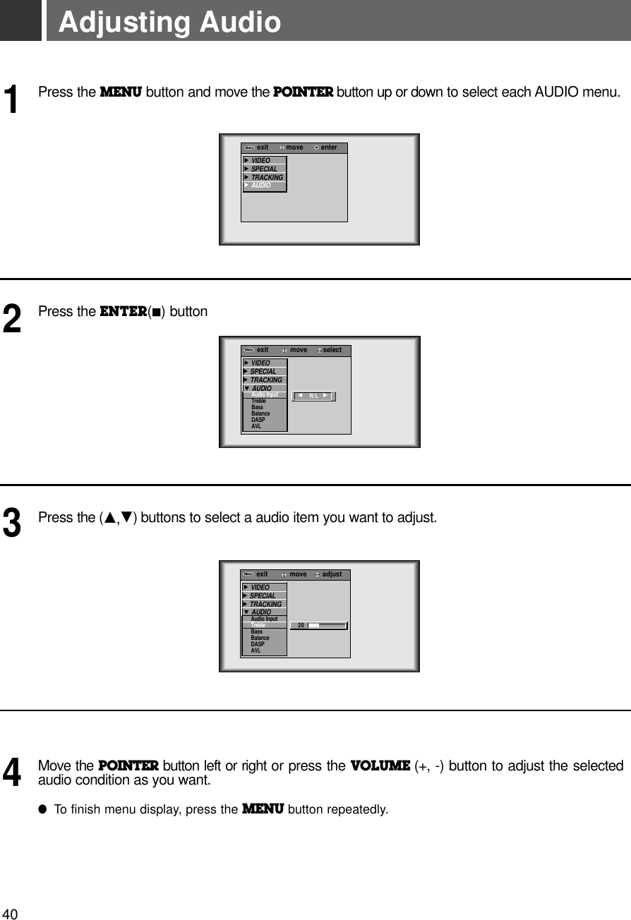
![Adjusting Video Press the MENU button and move the POINTER button up or down to select each VIDEO menu. 1Move the POINTER button up or down to select a video item you want to adjust.3Move the POINTER button left or right or press the VOLUME (+, -) button to adjust the selectedvideo item as you want. ●To restore the original image condition after changing it, press ENTER button after selecting [Reset] item(Only in RGB mode).●To finish menu display, press the MENU button.4Press the ENTER(A)button.2< RGB mode > < Video, S-Video, Component mode >< RGB mode > < Video, S-Video, Component mode >exit move enterMenuMenuGVIDEOGSPECIALG TRACKINGG AUDIOexit move adjustMenuMenuEVIDEOContrastBrightnessColor RColor GColor BReset GSPECIALG TRACKINGG AUDIO80exit move enterMenuMenuGVIDEOGSPECIALG AUDIOexit move adjustMenuMenuEVIDEOContrastBrightnessColor TintSharpnessAPC GSPECIALG TRACKINGG AUDIO8038](https://usermanual.wiki/LG-Electronics-USA/MW60SZ12/User-Guide-272543-Page-38.png)
![•Use this function to specify monitor ID number.SET IDPress the MENU button and move the POINTER button up or down to select the SPECIAL menu. 1Press the ENTER(A)button and move the POINTER button up or down to select the [Set ID].2Move the POINTER button left or right to adjust Set ID to choose the desired monitor ID number.● The adjustment range of Set ID is 1~99. ● If monitor have specified ID number, the choosed monitor operates only.● To exit the menu display, press the MENU button. 3exit move enterMenuMenuGVIDEOGSPECIALG TRACKINGG AUDIOexit move selectMenuMenuG VIDEOESPECIALLanguageHorizontalVerticalARCZoomLamp TimeSet IDG TRACKINGG AUDIO1External control device setup* Connect the RS-232C input jack to an external control device (such as a computer or an A/V control system)and control the Monitor’s functions externally.*When you connect a control(RS-232C) cable to this monitor, use a control cable with a ferrite core attached.If you do not do this, this monitor will not conform to mandatory CISPR22(EN55022) standards.44](https://usermanual.wiki/LG-Electronics-USA/MW60SZ12/User-Guide-272543-Page-44.png)
![Command Reference ListExternal control device setup461. Transmission* [Command 1] : To classify factory adjustment mode or user adjustment mode.(ASCII code, 1 Character)* [Command 2-1] : Group classification code to control set.(ASCII code, 1 Character)➜ Shortening Key Group :0, Video Group : 3. Audio Group:5, PIP Group :7, Others : 9* [Command 2-2] : To control monitor set.* [Set ID] : You can adjust the set ID to choose desired monitor ID number in special menu. See previous page. Adjustment range is 1 ~ 99. When selecting Set ID ‘0’, every connected monitor set is controlled.* [DATA] : To transmit command data. Transmit 2 character when organized ASCII code.* Transmit ‘FF’ data to read status of command.* [Cr] : Carriage ReturnASCII code ‘0x0D’ENTER Key* [ ] : ASCII code character correspond to “Space Bar” which is in order to classify command set ID and Data.[Command1][Command2-1][Command2-2][ ][Set ID][ ][Data][Cr]*The Monitor transmits ACK (acknowledgement) based on this format when receiving normal data. At this time, if the data is data read mode, it indicates present status data. If the data is data write mode, it returns the data of the PC computer.[Command2-1][Command2-2][ ][Set ID][ ][OK][Data][X][Command2-1][Command2-2][ ][Set ID][ ][NG][Data][X]2. Error Acknowledge*The Monitor transmits ACK (acknowledgement) based on this format when receiving abnormal data from non-viable functions or communication errors.Data : [01] : illegal code(This command is not supported.)[02] : not support function(This function doesn’t work.)[03] : wait more time(Try again a few ninute later.)❑ Communication ProtocolCommand1 Command2-1 Command2-2 SET ID Data(Hexa) Data(Hexa)01. Power k 0 0 00 ~ 63 00, 0102. Input Select k 0 1 00 ~ 63 00~0503. Aspect Ratio k 0 2 00 ~ 63 00~0204. Screen Mute k 0 3 00 ~ 63 00, 0105. Volume Mute k 5 4 00 ~ 63 00, 0106. Volume Control k 5 0 00 ~ 63 00~6407. Contrast k 3 0 00 ~ 63 00~6408. Brightness k 3 1 00 ~ 63 00~6409. Color k 3 2 00 ~ 63 00~6410. Tint k 3 3 00 ~ 63 00~6411. Sharpness k 3 4 00 ~ 63 00~6412. OSD select k 9 0 00 ~ 63 00, 0113. Remote Control lock k 9 1 00 ~ 63 00, 0114. Treble k 5 1 00 ~ 63 00~6415. Bass k 5 2 00 ~ 63 00~6416. Balance k 5 3 00 ~ 63 00~6417. Color R k 3 6 00 ~ 63 00~6418. Color G k 3 7 00 ~ 63 00~6419. Color B k 3 8 00 ~ 63 00~64](https://usermanual.wiki/LG-Electronics-USA/MW60SZ12/User-Guide-272543-Page-46.png)
![47RS-232C01. Power (Command2-1:0, Command2-2:0)➜To control Power On/Off of the Monitor.TransmissionData 00 : Power Off01 : Power On [k] [0] [0] [Set ID] [ ] [Data] [Cr][k] [0] [0] [ ] [Set ID] [ ] [FF] [Cr][0] [0] [ ] [Set ID] [ ] [OK] [Data] [X][0] [0] [ ] [Set ID] [ ] [OK] [Data] [X]AckAckData 00 : Power Off01 : Power On➜To show Power On/Off.TransmissionData 00 : Power Off01 : Power On*In like manner, if other functions transmit ‘FF’ data based on this format, Acknowledgement data feed back presents status about each function.02. Input Select (Command2-1:0, Command2-2:1)➜To select input source for the Monitor. TransmissionData 00 : RGB1 01 : RGB2 02 : RGB303 : Video 04 : S-Video 05 : ComponentData 00 : RGB1 01 : RGB2 02 : RGB303 : Video 04 : S-Video 05 : Component[k] [0] [1] [ ] [Set ID] [ ] [Data] [Cr][0] [1] [ ] [Set ID] [ ] [OK] [Data] [X]Ack03. Aspect Ratio (Command2-1:0, Command2-2:2)➜To adjust the screen format.TransmissionData 00 : Wide screen (16:9)01 : Normal screen (4:3) 02 : Full screen (Zoom 1) 03 : Zoom 204 : Zoom 3Data 00 : Wide screen (16:9)01 : Normal screen (4:3) 02 : Full screen (Zoom 1) 03 : Zoom 204 : Zoom 3[k] [0] [2] [ ] [Set ID] [ ] [Data] [Cr][0] [2] [ ] [Set ID] [ ] [OK] [Data] [X]Ack* Using the PC input, you select either 16:9 or 4:3 screen aspect ratio.04. Screen Mute (Command2-1:0, Command2-2:3)➜To select screen mute on/off.TransmissionData 01 : Screen Mute On (Picture Off)00 : Screen Mute Off (Picture On)Data 01 : Screen Mute On (Picture Off)00 : Screen Mute Off (Picture On)[k] [0] [3] [ ] [Set ID] [ ] [Data] [Cr][0] [3] [ ] [Set ID] [ ] [OK] [Data] [X]Ack05. Volume Mute (Command2-1:5, Command2-2:4)➜To control volume mute on/off.TransmissionData 00 : Volume Mute On (Volume Off)01 : Volume Mute Off (Volume On)Data 00 : Volume Mute On (Volume Off)01 : Volume Mute Off (Volume On)[k] [5] [4] [ ] [Set ID] [ ] [Data] [Cr][5] [4] [ ] [Set ID] [ ] [OK] [Data] [X]Ack](https://usermanual.wiki/LG-Electronics-USA/MW60SZ12/User-Guide-272543-Page-47.png)
![External control device setup4807. Contrast (Command2-1:3, Command2-2:0)➜To adjust screen contrast. TransmissionData Min : 00 ~ Max : 64* Refer to ‘Real data mapping 1’.Data Min : 00 ~ Max : 64[k] [3] [0] [ ] [Set ID] [ ] [Data] [Cr][3] [0] [ ] [Set ID] [ ] [OK] [Data] [X]Ack08. Brightness (Command2-1:3, Command2-2:1)➜To adjust screen brightness.TransmissionData Min : 00 ~ Max : 64* Refer to ‘Real data mapping 1’.Data Min : 00 ~ Max : 64[k] [3] [1] [ ] [Set ID] [ ] [Data] [Cr][3] [1] [ ] [Set ID] [ ] [OK] [Data] [X]Ack09. Color (Command2-1:3, Command2-2:2)➜To adjust the screen color.TransmissionData Min : 00 ~ Max : 64* Refer to ‘Real data mapping 1’.Data Min : 00 ~ Max : 64[k] [3] [2] [ ] [Set ID] [ ] [Data] [Cr][3] [2] [ ] [Set ID] [ ] [OK] [Data] [X]Ack10. Tint (Command2-1:3, Command2-2:3)➜To adjust the screen tint.TransmissionData Min : 00 ~ Max : 64* Refer to ‘Real data mapping2’.Data Min : 0 ~ Max : 64* This is a Hexadecimal number data.[k] [3] [3] [ ] [Set ID] [ ] [Data] [Cr][3] [3] [ ] [Set ID] [ ] [OK] [Data] [X]Ack* Real data mapping 10: Step 0A: Step 10F : Step 1510 : Step 1664 : Step 100* Real data mapping 20 : Step -5032 : Step 064 : Step 5011. Sharpness (Command2-1:3, Command2-2:4)➜To adjust the screen sharpness.TransmissionData Min : 00 ~ Max : 64* Refer to ‘Real data mapping 1’.Data Min : 00 ~ Max : 64[k] [3] [4] [ ] [Set ID] [ ] [Data] [Cr][3] [4] [ ] [Set ID] [ ] [OK] [Data] [X]Ack12. OSD Select (Command2-1:9, Command2-2:0)➜To select OSD (On Screen Display) On/Off.TransmissionData 00 : OSD Off01 : OSD OnData 00 : OSD Off01 : OSD On[k] [9] [0] [ ] [Set ID] [ ] [Data] [Cr][9] [0] [ ] [Set ID] [ ] [OK] [Data] [X]Ack06. Volume Control (Command2-1:5, Command2-2:0)➜To adjust volume.TransmissionData Min : 00 ~ Max : 64* Refer to ‘Real data mapping 1’.Data Min : 00 ~ Max : 64[k] [5] [0] [ ] [Set ID] [ ] [Data] [Cr][5] [0] [ ] [Set ID] [ ] [OK] [Data] [X]Ack](https://usermanual.wiki/LG-Electronics-USA/MW60SZ12/User-Guide-272543-Page-48.png)
![49RS-232C14. Treble (Command2-1:5, Command2-2:1)➜To adjust treble.TransmissionData Min : 00 ~ Max : 64* Refer to ‘Real data mapping 1’.Data Min : 00 ~ Max : 64[k] [5] [1] [ ] [Set ID] [ ] [Data] [Cr][5] [1] [ ] [Set ID] [ ] [OK] [Data] [X]Ack15. Bass (Command2-1:5, Command2-2:2)➜To adjust bass.TransmissionData Min : 00 ~ Max : 64* Refer to ‘Real data mapping 1’.Data Min : 00 ~ Max : 64[k] [5] [2] [ ] [Set ID] [ ] [Data] [Cr][5] [2] [ ] [Set ID] [ ] [OK] [Data] [X]Ack16. Balance (Command2-1:5, Command2-2:3)➜To adjust balance.TransmissionData Min : 00 ~ Max : 64* Refer to ‘Real data mapping 2’.Data Min : 00 ~ Max : 64[k] [5] [3] [ ] [Set ID] [ ] [Data] [Cr][5] [3] [ ] [Set ID] [ ] [OK] [Data] [X]Ack13. Remote Control lock (Command2-1:9, Command2-2:1)➜To lock the front panel controls on the monitor and remote control.TransmissionData 00 : Lock Off01 : Lock OnData 00 : Lock Off01 : Lock On[k] [9] [0] [ ] [Set ID] [ ] [Data] [Cr][9] [0] [ ] [Set ID] [ ] [OK] [Data] [X]Ack* If you’re not use the remote control, set this mode. 17. Color R Adjustment (Command2-1:3, Command2-2:6)➜ To adjust red in color temperature.TransmissionData Min : 00 ~ Max : 64* Refer to ‘Real data mapping 1’.Data Min : 00 ~ Max : 64[k] [3] [6] [ ] [Set ID] [ ] [Data] [Cr][3] [6] [ ] [Set ID] [ ] [OK] [Data] [X]Ack18. Color G Adjustment (Command2-1:3, Command2-2:7)➜ To adjust green in color temperature.TransmissionData Min : 00 ~ Max : 64* Refer to ‘Real data mapping 1’.Data Min : 00 ~ Max : 64[k] [3] [7] [ ] [Set ID] [ ] [Data] [Cr][3] [7] [ ] [Set ID] [ ] [OK] [Data] [X]Ack19. Color B Adjustment (Command2-1:3, Command2-2:8)➜ To adjust blue in color temperature.TransmissionData Min : 00 ~ Max : 64* Refer to ‘Real data mapping 1’.Data Min : 00 ~ Max : 64[k] [3] [8] [ ] [Set ID] [ ] [Data] [Cr][3] [8] [ ] [Set ID] [ ] [OK] [Data] [X]Ack](https://usermanual.wiki/LG-Electronics-USA/MW60SZ12/User-Guide-272543-Page-49.png)