LG Electronics USA MW60SZ12 LCD Projection Monitor User Manual
LG Electronics USA LCD Projection Monitor
User Manual
P/NO : 3828VA0349A b (373-026H)
MW-60SZ12
OWNER’S MANUAL
LCD PROJECTION MONITORLCD PROJECTION MONITOR
Please read this manual carefully before operating
your set.
Retain it for future reference.
Record model number and serial number of the set.
See the label attached on the back of the set and
quote this information to your dealer when you
require service.
Model number :
Serial number :
LCD PROJECTION MONITOR
LCD PROJECTION MONITOR
FCC NOTICE
• A Class B digital device
This equipment has been tested and found to comply with the limits for a Class B digital
device, pursuant to Part 15 of the FCC Rules. These limits are designed to provide
reasonable protection against harmful interference in a residential installation.
This equipment generates, uses and can radiate radio frequency energy and, if not
installed and used in accordance with the instructions, may cause harmful interference
to radio communications. However, there is no guarantee that interference will not occur
in a particular installation. If this equipment does cause harmful interference to radio or
television reception, which can be determined by turning the equipment off and on,
the user is encouraged to try to correct the interference by one or more of the
following measures:
- Reorient or relocate the receiving antenna.
- Increase the separation between the equipment and receiver.
- Connect the equipment into an outlet on a circuit different from that to which the
receiver is connected.
- Consult the dealer or an experienced radio/TV technician for help.
• Any changes or modifications not expressly approved by the party responsible for
compliance could void the user’s authority to operate the equipment.
Warning
This is a class B product. In a domestic environment this product may cause radio
interference, in which case the user may be required to take adequate measures.

Before operating the
unit, please read this
manual carefully.
CONTENTS
INTRODUCTION
Safety Instructions ..................................................................4
Names of parts .....................................................................12
COMPOSITION
Turning on the Monitor..........................................................18
Turning off the Monitor..........................................................19
Selecting source mode .........................................................20
CONNECTION
Connecting to a Desktop PC ................................................21
Connecting to a Notebook PC..............................................22
Connecting to a Macintosh Desktop PC...............................23
Connecting to a Macintosh PowerBook ...............................24
Connecting to a Video Source..............................................25
Connecting to a DVD............................................................26
Connecting to a D-TV Set-Top Box ......................................27
Connecting to a MIC.............................................................28
BASIC FUNCTIONS
Function checking.................................................................29
Using Still function ................................................................30
SPECIAL FUNCTIONS
Selecting language ...............................................................31
Checking lamp time ..............................................................32
Positioning ............................................................................33
Using Zoom function.............................................................34
Using ARC function ..............................................................35
TRACKING
Using Tracking function ........................................................36
VIDEO
Adjusting Video.....................................................................38
AUDIO
Adjusting Audio.....................................................................40
Using Audio Input function....................................................41
Using DASP function ............................................................42
Using AVL function................................................................43
RS-232C
External control device setup ...............................................44
INFORMATION
Supported Monitor Display ...................................................50
Specifications .......................................................................51
4
Safety Instructions
GGAlways keep the safety instructions to prevent any potential accident or misuse of the monitor.
GG After reading this manual, keep it in the place that the user always can contact easily.
GGSafety Instructions have two kinds of information, and each meaning of it is as below.
WARNING This instruction may cause serious or fatal injuries.
NOTES This instruction may cause light personal injuries or damage to the monitor.
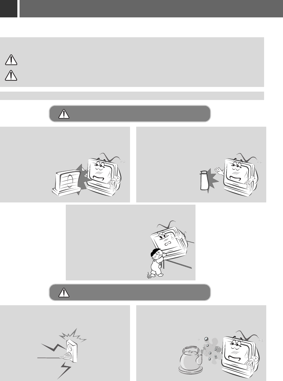
Indoor Installation-WARNING
Indoor Installation-NOTES
Do not place the Monitor in direct sunlight or
near heat sources such as radiators, fires and
stove etc.
- This may cause a fire hazard !
Disconnect from the mains and remove all
connections before moving.
Do not place the monitor close to sources
of steam or oil such as a humidifier.
- This may create a fire hazard or an
electric shock
hazard !
Do not place inflammable materials
beside the monitor.
- This may cause a fire hazard !
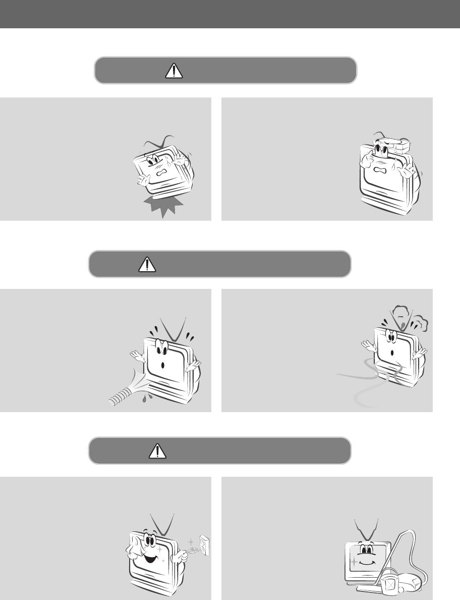
Do not allow children hang on or climb on
the installed monitor.
- This may cause the display to
fall, causing a fatal injury.
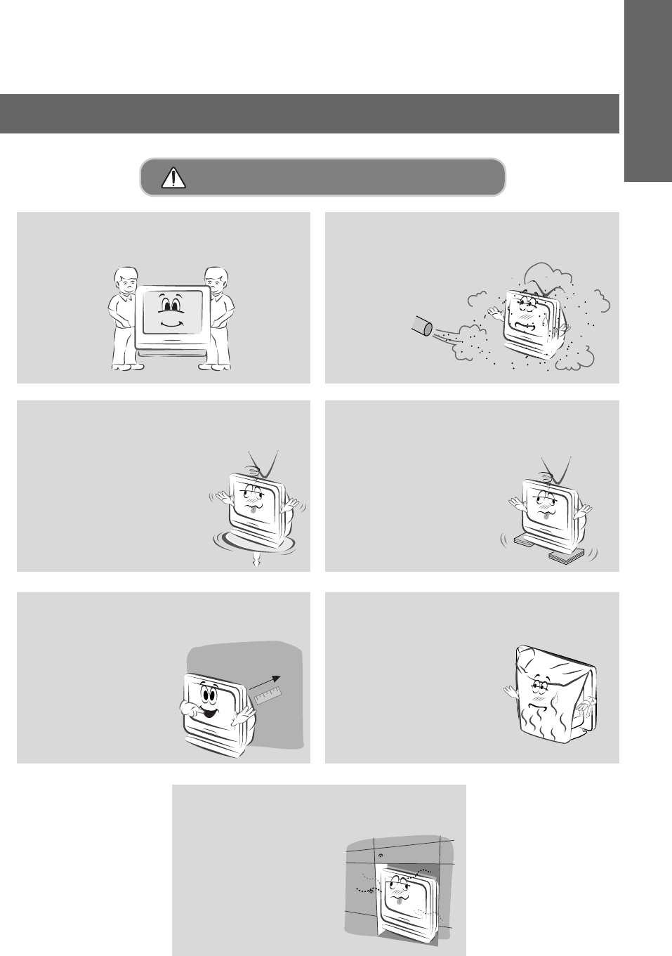
When unpacking or moving the Monitor two
people will be necessary to lift it safely.
Do not place the monitor where it might
be exposed to dust.
- This may cause a fire hazard !
When installing the monitor on a table, be
careful not to place it near the edge.
- This may cause the monitor to fall
causing serious personal injury
and serious damage to the
monitor.
-Be sure to use a suitable
table or rack.
Only use the monitor on a level and sta-
ble surface.
- Else it may become unstable and
affect correct operation.
Ensure good ventilation around the moni-
tor. The distance between the monitor and
the wall should be more
than 10cm.
- Else the internal
temperature of the
monitor will increase
and create a fire
hazard.
Do not cover the vent grilles of the moni-
tor.
- This may cause a fire
hazard !
Do not place the monitor directly on a car-
pet, rug or place where ventilation is
restricted.
- This would cause its
internal temperature to
increase and might
create a fire hazard !
5
INTRODUCTION
Indoor Installation-NOTES
6
Safety Instructions
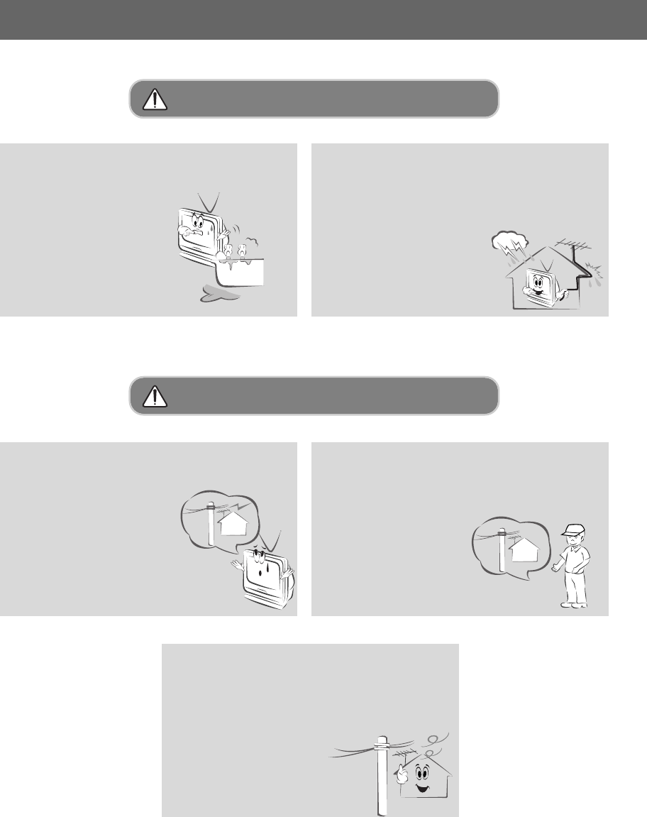
Do not use the monitor in a damp place
such as a bathroom where it is likely to get
wet.
- This may cause a fire or an
electric shock hazard !
In the case of using a receiver (VCR,
Digital Set Top Box), be sure to position
the antenna cable between inside and
outside of the building to prevent rain from
flowing in.
-Else this may cause water
damage inside the monitor
and create an electric shock
hazard.
In the case of using a receiver (VCR,
Digital Set Top Box), do not place an
antenna in the vicinity of
power lines.
- This may create an
electric shock hazard.
In the case of using a receiver (VCR,
Digital Set Top Box), arrange qualified
personnel to install an outside antenna.
- This job involves risk of
personal injury.
In the case of using a receiver (VCR,
Digital Set Top Box), there should be
enough distance between an outside
antenna and power lines to prevent con-
tact should the antenna fall.
- This may create an
electric shock hazard.
Outdoor Installation-WARNING
Outdoor Installation-NOTES
7
INTRODUCTION
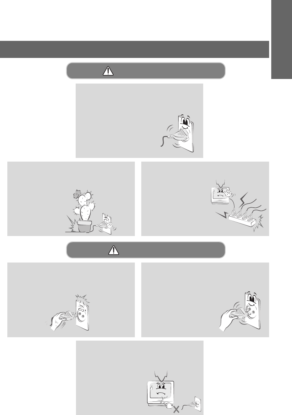
Do not place heavy objects on the power
cord
- This may cause a fire or an electric
shock hazard !
Do not use too many plugs on the Mains
multi-outlet.
- It may result in
overheating of the
outlet and causes a
fire hazard !
The mains plug should be inserted fully
into the power outlet to avoid a fire
hazard !
- Else this may cause a
fire hazard !
Hold the plug firmly when unplugging. If
you pull the cord, the cord may be dam-
aged.
- This may cause a fire hazard !
Never touch the power plug with a wet
hand
- This may cause an electric shock hazard !
Power-WARNING
Power-NOTES
Do not turn the monitor On/Off by plugging-
in or unplugging the power plug from the
wall outlet.(Do not use the power plug
as a switch.)
- Else this may cause
mechanical failure
or could create an
electric shock or fire
hazard.
8
Safety Instructions
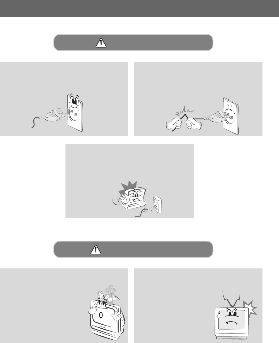
Prevent dust collecting on the power plug
pins or outlet.
- This may cause a fire hazard !
Do not plug when the power cord or the
plug is damaged or the connecting part of
the power outlet is loose.
- This may cause a fire or an electric shock
hazard !
Ensure the power cord does not come into
contact with sharp or hot objects such as a
heater.
- This may cause a fire or an electric shock
hazard !
Do not place anything containing liquid on
top of the monitor such as flowerpot,
cup, cosmetics or candle.
- This may cause a fire hazard !
In case of impact shock or damage to the
monitor switch it off and unplug it from the
outlet and contact your
service center.
- This may cause a fire or an
electric shock hazard !
Power-NOTES
Using-WARNING
9
INTRODUCTION
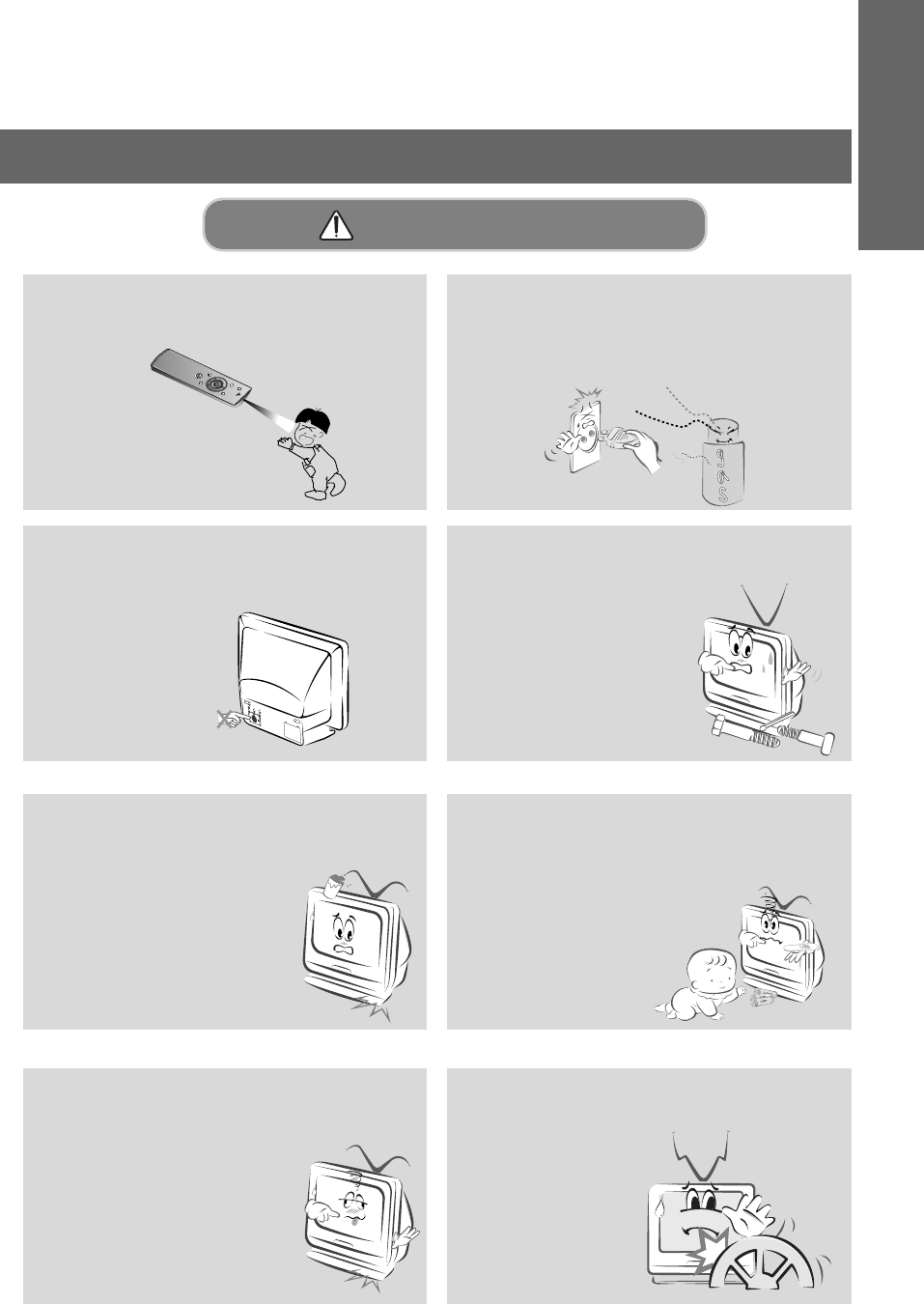
Do not open the lamp cover because the
lamp operates at high pressure and high
temperature.
Do not allow any objects to fall into the
monitor.
- This may cause an electric shock
hazard !
If water is spilt into the monitor unplug it
from the main supply outlet immediately and
consult your Service Center.
- This may cause an electric
shock hazard !
Dispose of used batteries carefully and
safely.
- In the case of a battery being swallowed by a
child please consult a doctor
immediately.
In the event that an image does not
appear on the screen please switch it off
and unplug it from the main
supply and contact your
Service Center.
- This may cause a fire or an
electric shock hazard !
Do not watch the monitor while driving or
walking.
- This may cause an
accident.
Using-WARNING
Don’t look at laser beam directly as it will
cause eye damage.
Never touch the wall outlet when there is
leakage of gas, open the windows and
ventilate.
- It can cause a fire or a burn by a spark.
10
Safety Instructions
Do not use water while cleaning the
Monitor.
- Else this may cause damage
to the Monitor or create an
electric shock hazard.
In the unlikely event of smoke or a
strange smell from the Monitor,
switch it off ,unplug it from the
wall outlet and contact your
dealer or service centre.
- This may cause a fire or
an electric shock hazard !
Cleaning-WARNING
Unplug this product from the wall outlet
before cleaning. Do not use liquid clean-
ers or aerosol cleaners.
- This may cause damage to
the Monitor or cause
an electric shock hazard !
Contact the service center once a year to
clean the internal part of the monitor.
- Accumulated dust can cause
mechanical failure.
Cleaning-NOTES
Do not drop the monitor or allow impact
shock.
- This may cause mechanical
failure or injury !
Do not place heavy objects on the
Monitor.
- This may cause serious injury to
a child or adult.
Using-NOTES
11
INTRODUCTION
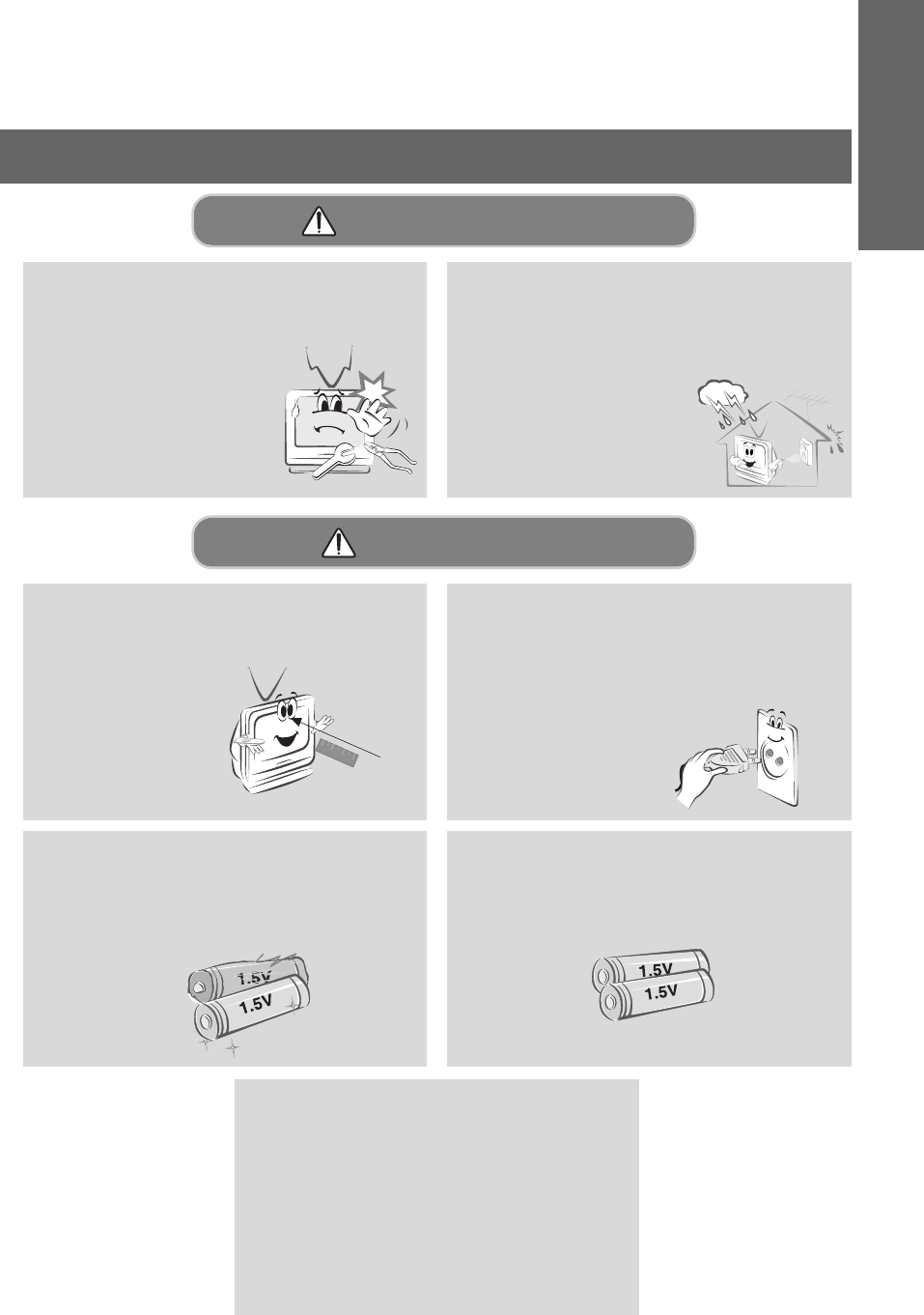
Do not attempt to service the Monitor
yourself. Contact your dealer or service
centre.
- This may cause damage to the
Monitor and could give an
electric Shock as well as
invalidating the warranty !
In the event of a lightning or thunder
storm unplug the Monitor and aerial from
the wall outlet.
- This will prevent damage to the Monitor
and possible electric shock.
Others-WARNING
The distance between eyes and the
screen should be about 1.5m.
- If not, eyes will strain.
Unplug the Monitor from the wall outlet
when it is left unattended and unused for
long periods of time.
- Accumulated dust may cause a fire or an
electric shock from
deterioration or
electric leakage.
Only use the specified batteries.
- Else this may cause damage to the Remote
Control.
Avoid having a fixed image remain on the
screen for a long period time. A frozen still
picture from a VCR(or 4:3 aspect ratio)
displayed on the screen for prolonged
periods of time, will result in a ghost
image remaining even when you change
the image.
Others-NOTES
Do not mix new batteries with old batter-
ies.
- This can cause batteries to overheat and
leak causing personal injury and damage to
the remote control.
12
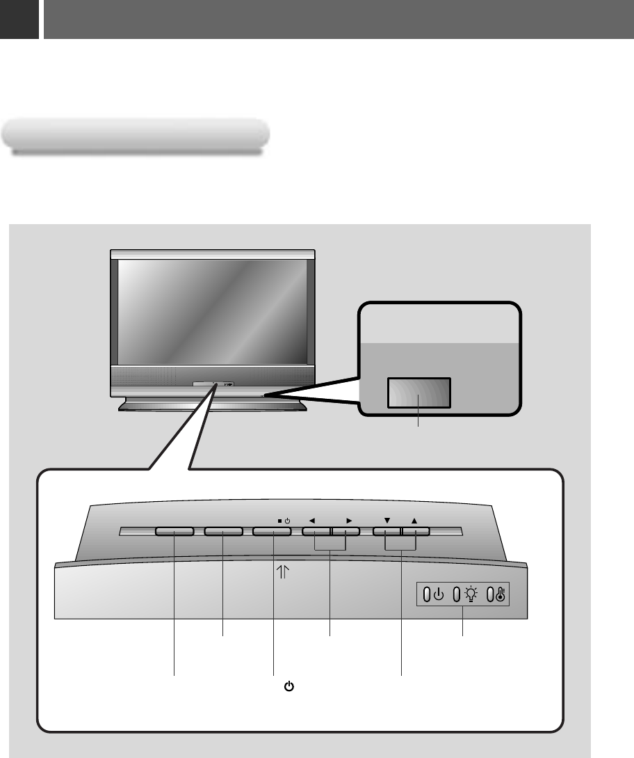
Names of parts
ON/OFF
ON/OFF
SOURCE MENU VOLENTER
/
Main Body
Main Body
SOURCE Button ENTER A/ Button
ON/OFF Button
VOL F, GButton
E, DButton
Indicators
MENU Button
13
INTRODUCTION
R L
YP
B
P
R
RGB IN1 RGB IN2 RGB OUT
MOUSE
RS-232C
RS-232C
RGB IN3(DVI-I)
RGB IN3
(DVI-I)
PONENT
COM-
VIDEOS-VIDEO
DC OUT
(12V/0.5A) MIC
R L
YP
B
P
R
RGB IN1 RGB IN2 RGB OUT
MOUSE
RS-232CRGB IN3(DVI-I)
PONENT
COM
VIDEOS-VIDEO
DC OUT
(12V/0.5A) MIC
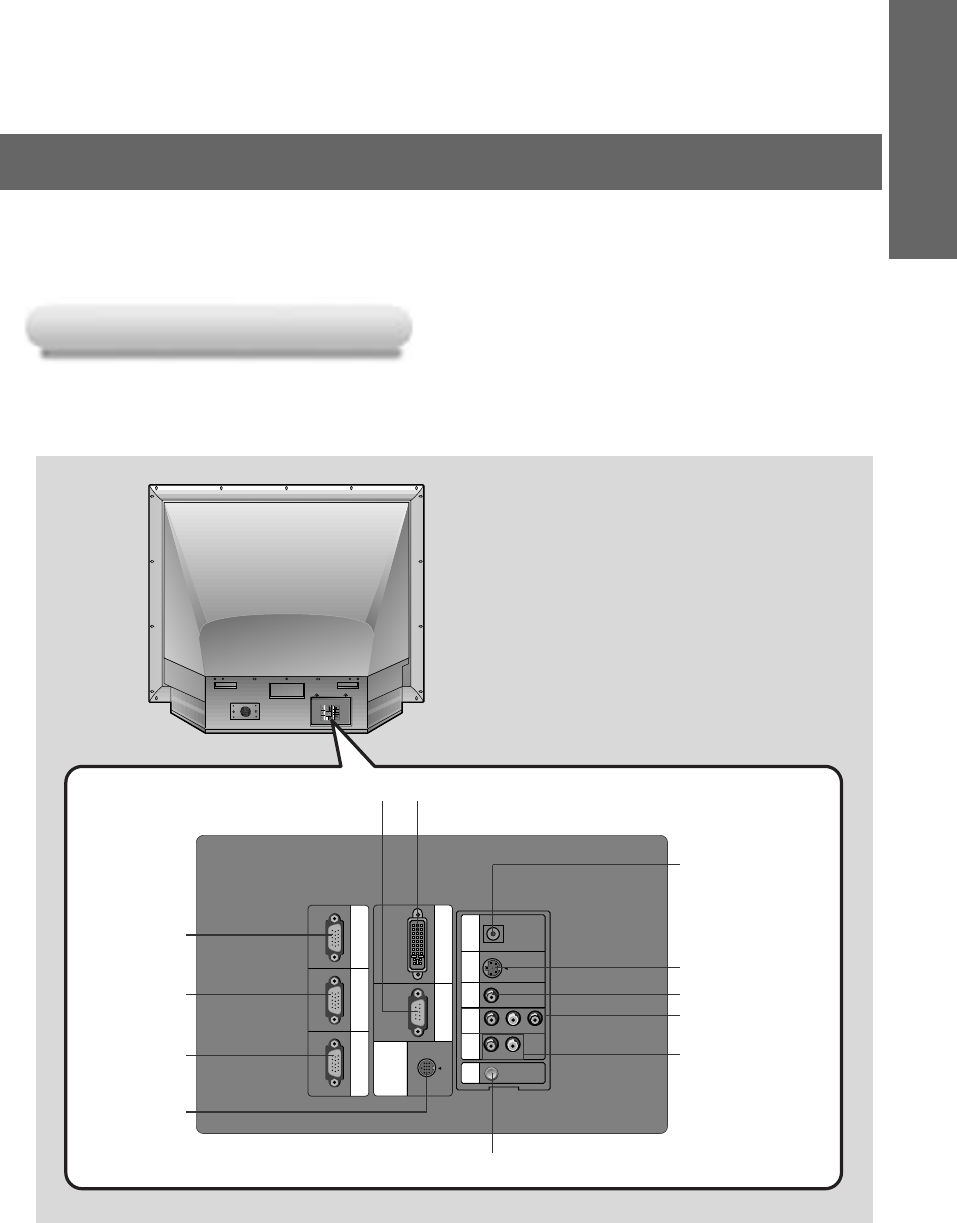
Rear Connecting Part
Rear Connecting Part
RGB IN1
RGB IN2
RGB OUT
MOUSE
MIC
RS-232C
COMPONENT
(Y, PB, PR)
R, L
VIDEO
S-VIDEO
RGB IN3(DVI-I)
DC OUT(12V/0.5A)
*Use this jack when
connecting the
wireless receiver to
the monitor.
14
Names of parts
POWER
SOURCE MENU
LR
ZOOM MUTE
LASER
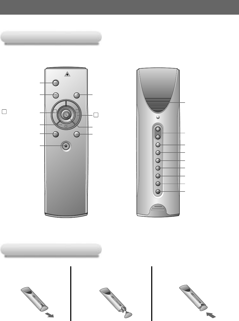
Remote Control
Remote Control
Inserting the batteries
Inserting the batteries
POWER Button
SOURCE Button
R MOUSE Button
(Zoom-in Button)
MOUSE DRAG
VOL.
STILL
ARC
AUTO
AVL
DASP
APC
MIC
MOUSE DRAG
Button
VOL. +, - Button
STILL Button
L MOUSE Button
(Zoom-out Button)
ARC Button
AVL Button
DASP Button
APC Button
MIC Button
AUTO Button
ZOOM Button
LASER Button
Slide the battery cover
in the direction of the
arrow to remove.
MENU Button
ENTERA Button POINTER Button
MUTE Button
*Switches the sound
on or off.
1
Insert the batteries with
correct polarity.
2
Replace the battery
compartment cover to
the arrow direction.
3
Functions on the Remote Control
Functions on the Remote Control
15
INTRODUCTION
Button
Button Function
Function
POWER Button Selects ON/OFF of power.
SOURCE Button Switches to RGB1/2/3, Video, S-Video, Component mode.
MENU Button Displays or hides the menu.
L MOUSE Button * Corresponds to the Left - Click of PC Mouse.
(Zoom-out Button) * Downsizes the screen on the zoom function.
R MOUSE Button * Corresponds to the Right - Click of PC Mouse.
(Zoom-in Button) * Enlarges the screen size on zoom function.
POINTER Button * After selecting menus, controls selecting and adjusting
functions with the direction of up, down, left, right.
* Moves the screen with the direction of up, down, left, right
on zoom function.
* Moves and releases the selected icon on PC screen.
MOUSE DRAG Button Uses to select and drag an icon in PC mode.
ENTERAButton Checks the present mode and sets the change of functions.
ZOOM Button Refer to page 34.
MUTE Button Cuts off audio.
VOL.(+, -) Button Adjusts volume level.
STILL Button Refer to page 30.
ARC Button Refer to page 35.
AUTO Button
Refer to page 36.
AVL Button Refer to page 43.
DASP Button Refer to page 42.
APC Button Refer to page 39.
MIC Button Refer to page 41.
LASER Button Projects a bright red laser point on to the screen for indication
purposes.
(Don’t look at laser beam directly as it will cause eye
damage.)
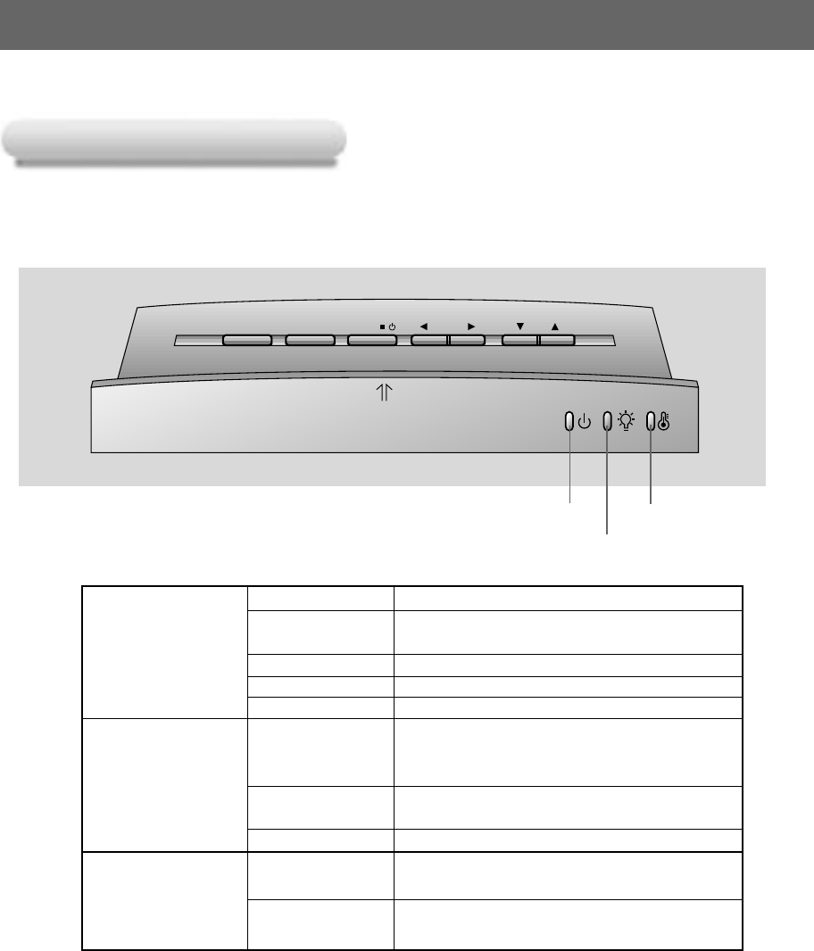
Names of parts
Monitor Status Indicators
Monitor Status Indicators
* Temperature indicator, lamp Indicator and operation indicator at the front of the monitor show the user the
operating status of the monitor.
“ ”
is the warning message on screen.
Orange Standby.
Operation Indicator
Green(flashing) Lamp cooling untill the lamp turn on.
(for 25 seconds)(Refer to P.18)
Green On operation.(Turn on the lamp)
Orange(flashing) Monitor lamp is cooling as power out(1 minutes)
Off Power off.
Monitor lamp is reaching the end of its life and needs
Red to be replaced with a new lamp.(over 10000 hours)
“Replace the Lamp”
Lamp Indicator
Red(flashing) The monitor has trouble in the lamp or around it.
Contact the service center.
Green(flashing) The lamp cover is not closed.
Temperature Indicator
Red
The monitor is turned off due to its high temperature.
Contact your service center.
Red(flashing) Power has turned off due to problem with the
Green(flashing) internal cooling fans. Contact your service center.
Lamp Indicator
Operation indicator Temperature indicator
16
SOURCE MENU VOLENTER
/
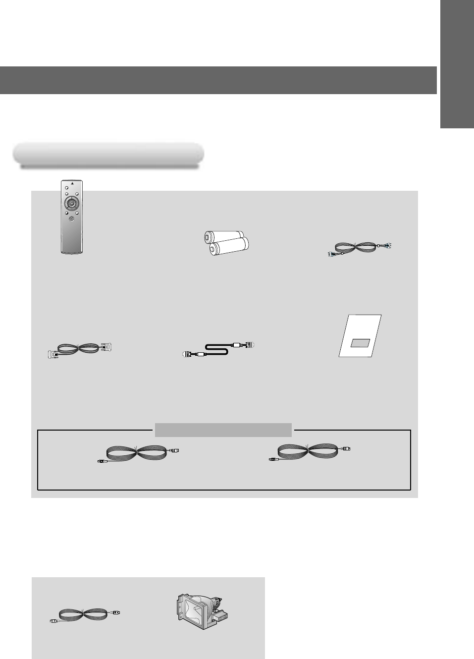
Accessories
Accessories
POWER
SOURCE MENU
LR
ZOOM MUTE
LASER
1.5V
1.5V
Mouse Connecting Cables
Optional Extras
* Contact your dealer for buying these items.
* Contact your dealer for replacing a new lamp.
Remote Control Batteries 2 (size AA) Audio/Video Cable
Computer Cable
MAC Serial Mouse Cable
DVI cable
Lamp
S-Video Cable
PS/2 Mouse Cable
(IBM PC or Compatible)
17
INTRODUCTION
Operating guide
18
Turning on the Monitor
Connect power cord correctly.
1
Press the ON/OFF button on the monitor. At this moment, the monitor is switched to standby
mode. Press any button on the keypad or POWER button on the remote control then the monitor
will be turned on.
2
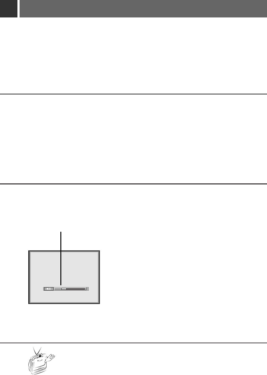
Adjust volume level.
●
If you press VOL. +button, volume level number is increased.
●
If you press VOL. -button, volume level number is decreased.
3
24
*Don’t turn main power off and don’t unplug the power cord while the ventilation
fan(inlet/outlet) is working.
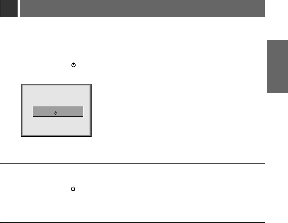
Press the ENTER A/ button on the keypad for 3 seconds or POWER button on the remote
control.
1
Press the ENTER A/ button or POWER button on the remote control again to switch off the
power.
2
If the operation indicator is flashing(orange), leave the power cord plugged into the outlet.
Do not pull out from the outlet until operation indicator is lit up(orange) constantly.
●
If operation indicator is flashing(orange), the power button on the top cover or remote
control may not operate.
3
Turning off the Monitor
Power Off?
Please Press Key Again.
19
COMPOSITION
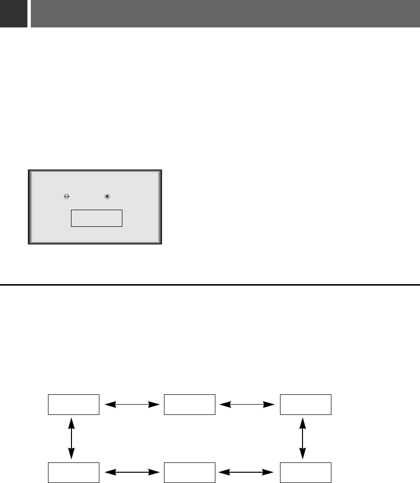
Press the SOURCE button
1
Move the POINTER button left or right. Each press of the POINTER button changes the display
as below.
2
RGB1 RGB2 RGB3
VideoS-VideoComponent
Selecting source mode
20
select enter
FRGB1 G
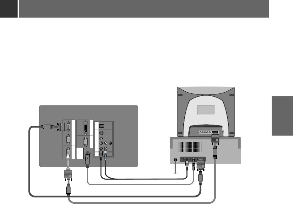
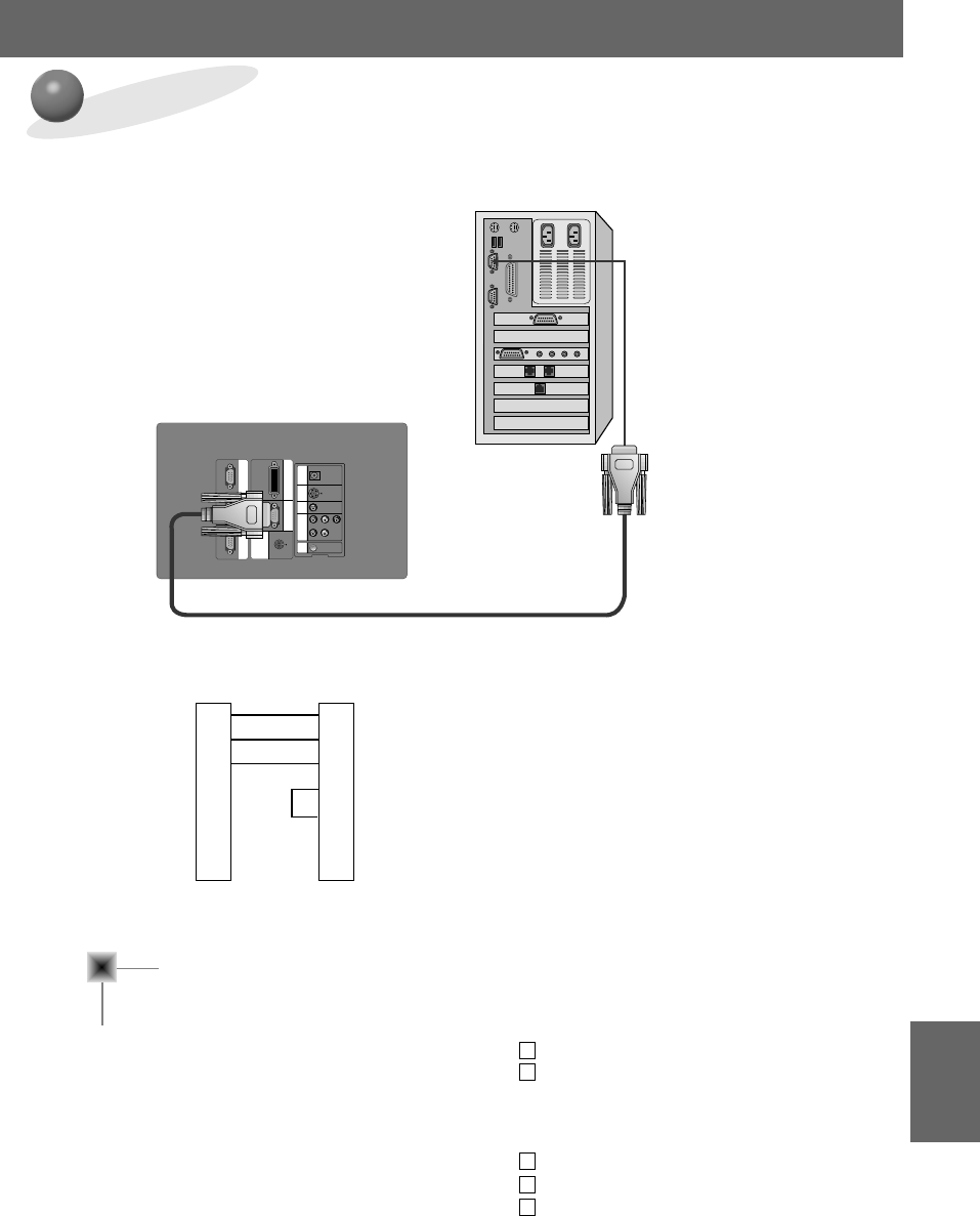
Connecting to a Desktop PC
* You can connect the monitor to a computer of VGA, SVGA, XGA and SXGA output.
* Refer to page 50 for the supported monitor display of this monitor.
< How to connect >
a. Connect either end of the computer cable to RGB IN1 or RGB IN2 of the monitor.
* If the PC has DVI output, connect DVI cable to RGB IN3.(RGB IN3 supports DVI-I)
b. Connect the monitor cable from the PC monitor to RGB OUT of the monitor if you want to also see the
monitor image on a PC monitor.
c. Connect either end of the audio cable to R, L ports of the monitor.
* Audio cables are not supplied with the Monitor.
d. Connect the PS/2 mouse(for IBM PC or compatible) cable(6 pin) to MOUSE of the monitor.
RGB IN1 RGB IN2 RGB OUT
MOUSE
RS-232CRGB IN3(DVI-I)
DVI-I
R L
YP
B
P
R
PONENT
COM
VIDEOS-VIDEO
DC OUT
(12V/0.5A) MIC
a
b
cd
21
CONNECTION
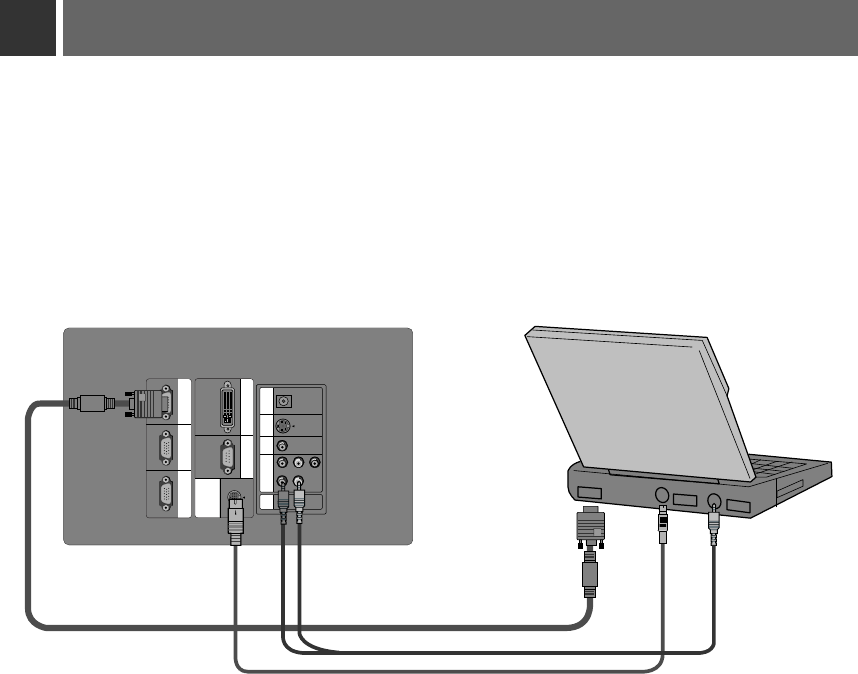
Connecting to a Notebook PC
< How to connect >
a. Connect either end of the computer cable to RGB IN1 or RGB IN2 of the monitor.
* If you set your computer, such as a notebook type IBM PC/AT compatible, to output the signal to both the display of
your computer and the external monitor, the picture of the external monitor may not appear properly. IN such cases,
set the output mode of your computer to output the signal only to the external monitor. For details, refer to the
operating instructions supplied with your computer.
* If the PC has DVI output, connect DVI cable to RGB IN3.(RGB IN3 supports DVI-I)
b. Connect either end of the audio cable to R, L ports of the monitor.
* Audio cables are not supplied with the Monitor.
c. Connect the PS/2 mouse(for IBM PC or compatible) cable(6 pin) to MOUSE of the monitor.
* If the mouse operation is not good, don’t use the mouse(Track Ball, Touch Pad, etc) within Notebook
PC.
RGB IN1 RGB IN2 RGB OUT
MOUSE
RS-232CRGB IN3(DVI-I)
R L
YP
B
P
R
PONENT
COM
VIDEOS-VIDEO
DC OUT
(12V/0.5A) MIC
a
bc
22
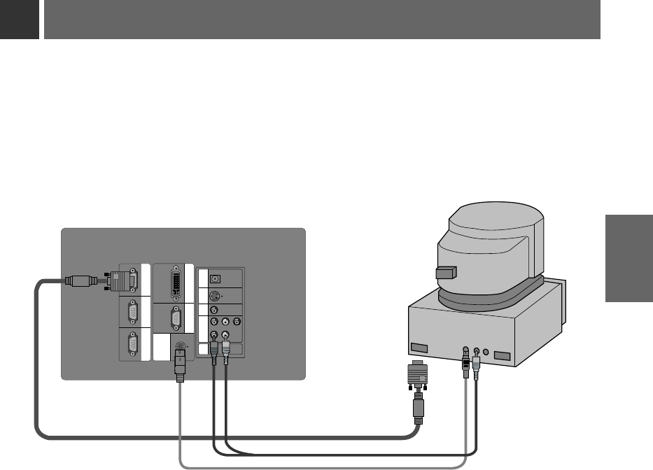
Connecting to a Macintosh Desktop PC
< How to connect >
a. Connect either end of the computer cable to RGB IN1 or RGB IN2 of the monitor.
b. Connect either end of the audio cable to R, L ports of the monitor.
* Audio cables are not supplied with the Monitor.
c. Connect the MAC serial mouse cable(4 pin) to MOUSE of the monitor.
RGB IN1 RGB IN2 RGB OUT
MOUSE
RS-232CRGB IN3(DVI-I)
R L
YP
B
P
R
PONENT
COM
VIDEOS-VIDEO
DC OUT
(12V/0.5A) MIC
c
b
a
23
CONNECTION
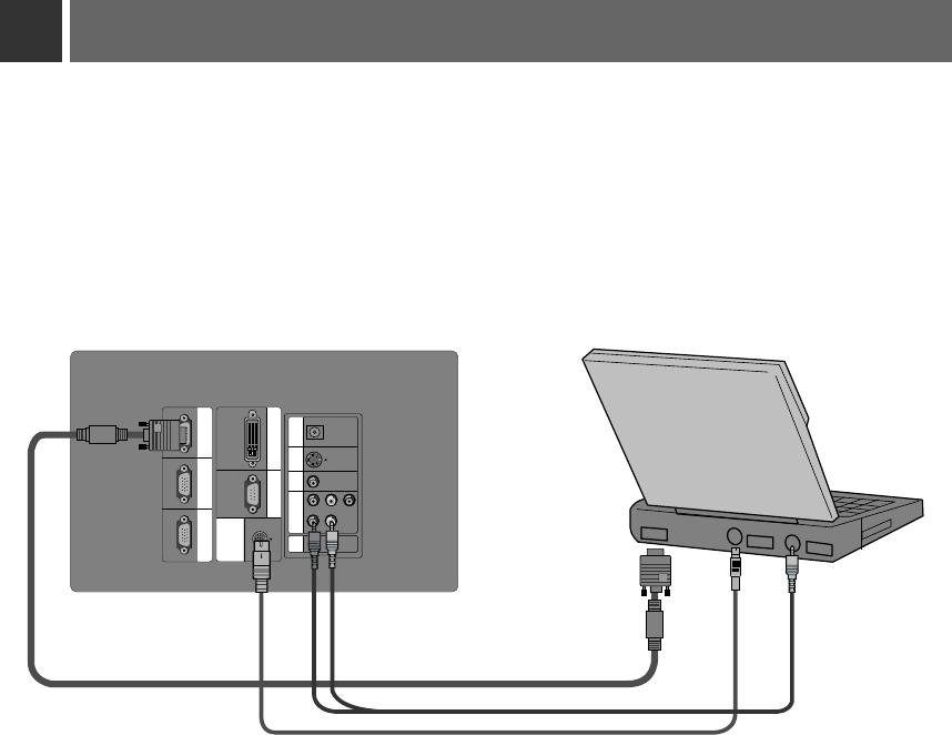
Connecting to a Macintosh PowerBook
< How to connect >
a. Connect either end of the computer cable to RGB IN1or RGB IN2 of the monitor.
b. Connect either end of the audio cable to R, L ports of the monitor.
* Audio cables are not supplied with the Monitor.
c. Connect the MAC serial mouse cable(4 pin) to MOUSE of the monitor.
RGB IN1 RGB IN2 RGB OUT
MOUSE
RS-232CRGB IN3(DVI-I)
R L
YP
B
P
R
PONENT
COM
VIDEOS-VIDEO
DC OUT
(12V/0.5A) MIC
a
bc
24
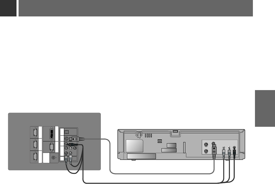
< How to connect-In case of connecting Video cable>
a. When connecting the monitor to an Video source, connect the VIDEO input ports of the monitor to the
output ports of the Video source with Audio/Video cables of the same color. The video cable is yellow and
the left audio is white and right audio is red.
< How to connect-In case of connecting S-Video cable>
b. Connect S-VIDEO input port of the monitor to S-Video output port of Video source with S-Video cable.
* You can get better picture quality when connecting S-Video source to the monitor.
* In AV input mode, if the auto video system recognition fails to detect a correct video system type, please press the
AUTO
button on the remocon. Then the monitor executes the fine auto video system recognition.
* You can connect a VTR, a camcorder, a LDP or any other compatible video image source to the monitor.
RGB IN1 RGB IN2 RGB OUT
MOUSE
RS-232CRGB IN3(DVI-I)
R L
YP
B
P
R
PONENT
COM
VIDEOS-VIDEO
DC OUT
(12V/0.5A) MIC
S VIDEO
(R) AUDIO (L) VIDEO
OUT
IN
b
Connecting to a Video Source
a
25
CONNECTION
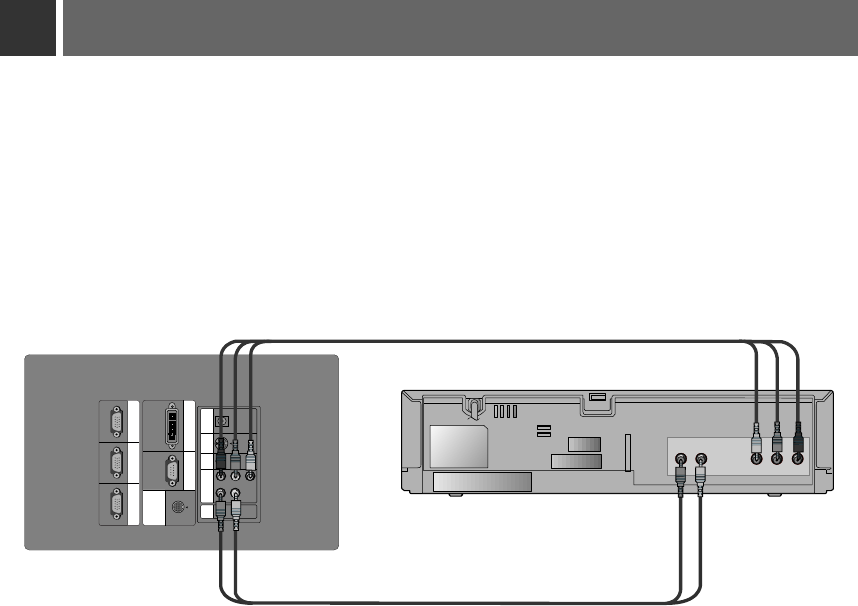
Connecting to a DVD
* The output ports (Y, PB, PR) of the DVD might be inscribed as Y, Pb, Pr / Y, B-Y, R-Y / Y, Cb, Cr according to the
equipments.
RGB IN1 RGB IN2 RGB OUT
MOUSE
RS-232CRGB IN3(DVI-I)
R L
YP
B
P
R
PONENT
COM
VIDEOS-VIDEO
DC OUT
(12V/0.5A) MIC
Pr
Pb
Y
(R) AUDIO (L)
a
b
< How to connect >
a. Connect the COMPONENT ports (Y, PB, PR) of the monitor to the Video output ports (Y, PB, PR) of the
DVD.
b. Connect the R, Lports of the monitor to the Audio output ports (R, L) of the DVD.
* Audio cables are not supplied with the Monitor.
26
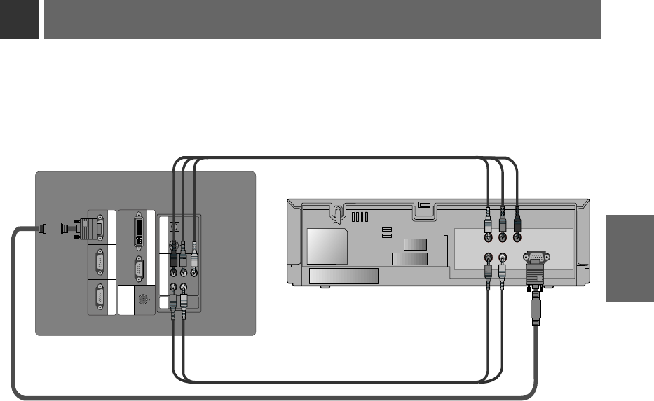
Connecting to a D-TV Set-Top Box
RGB IN1 RGB IN2 RGB OUT
MOUSE
RS-232CRGB IN3(DVI-I)
R L
YP
B
P
R
PONENT
COM
VIDEOS-VIDEO
DC OUT
(12V/0.5A) MIC
(R) AUDIO (L)
DTV OUTPUT
P
r
P
b
Y
< How to connect-In case of connecting RGB>
a. Connect either end of the computer cable to RGB IN1 of the monitor.
b. Connect the R, Lports of the monitor to the Audio output ports (R, L) of the D-TV Settop Box.
* Audio cables are not supplied with the Monitor.
c. Use a DTV receiver with DTV 720p/1080i mode.
< How to connect-In case of connecting Component>
a. Connect the COMPONENT ports (Y, PB, PR) of the monitor to the Video output ports (Y, Pb, Pr) of the
D-TV Set-Top Box.
b. Connect the R, Lports of the monitor to the Audio output ports (R, L) of the D-TV Set-Top Box.
* Audio cables are not supplied with the Monitor.
c. Use a DTV receiver with DTV 480p/720p/1080i mode.
* To receive the DTV program, it is necessary to purchase DTV receiver (Set-Top Box) and
connect it to the monitor.
* Please refer to the owner's manual of the DTV Set-Top Box for the connection to the LCD
Projection Monitor.
(RGB)
(Component)
(RGB, Component)
27
CONNECTION
28
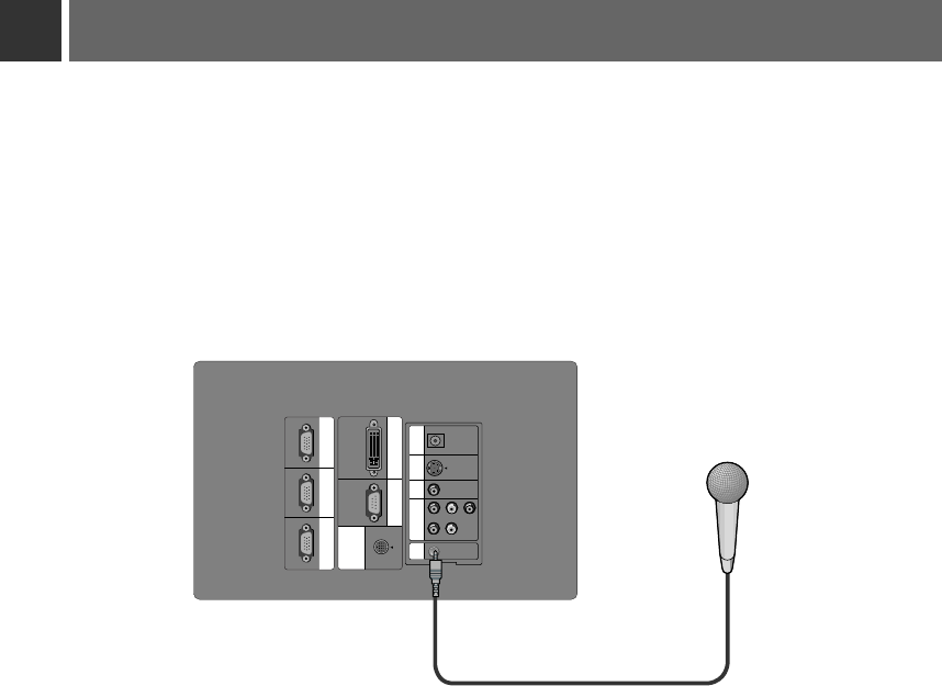
Connecting to a MIC
* It’s impossible to use R/L and MIC simultaneously.
RGB IN1 RGB IN2 RGB OUT
MOUSE
RS-232CRGB IN3(DVI-I)
R L
YP
B
P
R
PONENT
COM
VIDEOS-VIDEO
DC OUT
(12V/0.5A) MIC
< How to connect >
a. Connect the mike to MIC jack of the monitor.
b. To use the mike, select Audio input MIC.(See page 41.)
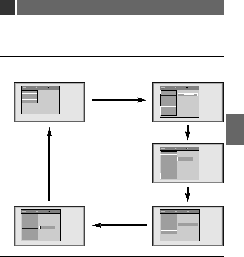
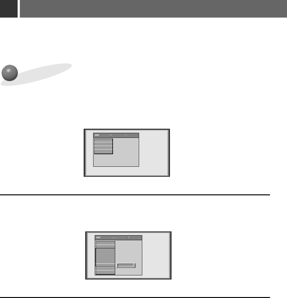
Function checking
3
Press the MENU button.
1
Move the POINTER button up or down to select a menu and press the ENTER(A) button. Each time
you press the button you can see menus as below.
Move the POINTER button up or down to select a function that you want to use or adjust.
●To finish the menu display, press the MENU button.
*In Video and S-Video mode and Component(480i) mode, [Horizontal], [Vertical] in SPECIAL menu are
not displayed.
* In Video and S-Video mode and Component(480i, 480p, 720p, 1080i)) mode TRACKING menu is not displayed.
*The sub menus of VIDEO menu in Video and S-Video mode and Component mode are different from those in the
RGB mode. (Refer to page 38).
2
*
If there is no input signal, Menu will not display on screen.
*
This operating guide explains operation of RGB (PC) mode mainly.
exit move enter
MenuMenu
G
VIDEO
G
SPECIAL
G
TRACKING
G
AUDIO
exit move adjust
MenuMenu
E
VIDEO
Contrast
Brightness
Color R
Color G
Color B
Reset
G
SPECIAL
G
TRACKING
G
AUDIO
exit move select
MenuMenu
G
VIDEO
E
SPECIAL
Language
Horizontal
Vertical
ARC
Zoom
Lamp Time
Set ID
G
TRACKING
G
AUDIO
exit move select
MenuMenu
G
VIDEO
G
SPECIAL
G
TRACKING
E
AUDIO
Audio Input
Treble
Bass
Balance
DASP
AVL
exit move enter
MenuMenu
G
VIDEO
G
SPECIAL
E
TRACKING
Auto Tracking
Clock
Phase
G
AUDIO
Press Enter to Start
F
English
G
F
R/L
G
80
29
BASIC
FUNCTIONS
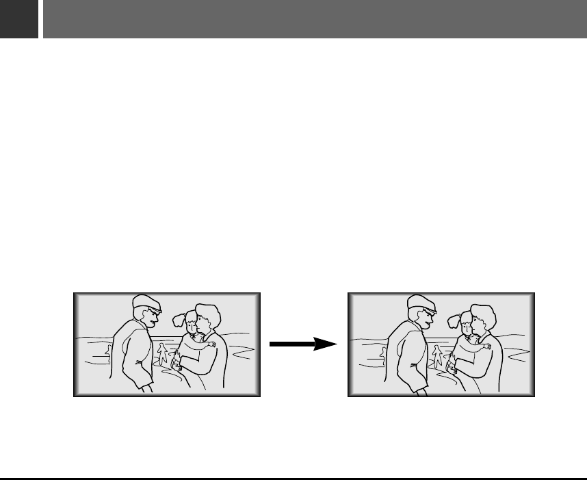
Using Still function
Press the STILL button.
* You can freeze the input image.
1
To finish this function, press the
STILL
button again.
* The STILL function would release automatically after about 10 minutes.
2
<Moving Image> <Still Image>
30
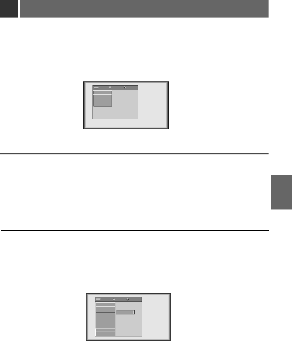
Selecting language
Press the MENU button and move the POINTER button up or down to select the SPECIAL menu
as below.
1
Press the ENTER(A)button and move the POINTER button up or down to select [Language] item.
Move the POINTER button left or right to select the language you want to use.
●
On-Screen-Display(OSD) is marked in the selected language from this point.
●
To finish menu display, press the MENU button.
2
3
exit move enter
MenuMenu
G
VIDEO
G
SPECIAL
G
TRACKING
G
AUDIO
exit move select
MenuMenu
G
VIDEO
E
SPECIAL
Language
Horizontal
Vertical
ARC
Zoom
Lamp Time
Set ID
G
TRACKING
G
AUDIO
F
English
G
31
SPECIAL
FUNCTIONS
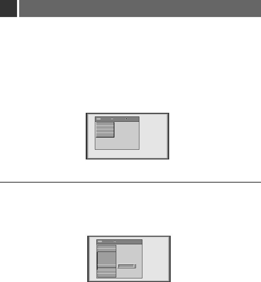
Checking lamp time
Press the MENU button and move the POINTER button up or down to select the SPECIAL menu
as below.
1
Press the ENTER(A)button and move the POINTER button up or down to select the [Lamp Time]
item.
2
●
You can see the used lamp time.
●
When monitor lamp is reaching the end of its life(over 10000 hours), the lamp indicator will be turned
red and the monitor will display “Replace the Lamp” on screen.
exit move enter
MenuMenu
G
VIDEO
G
SPECIAL
G
TRACKING
G
AUDIO
exit move
MenuMenu
G
VIDEO
E
SPECIAL
Language
Horizontal
Vertical
ARC
Zoom
Lamp Time
Set ID
G
TRACKING
G
AUDIO
0 Hr
32
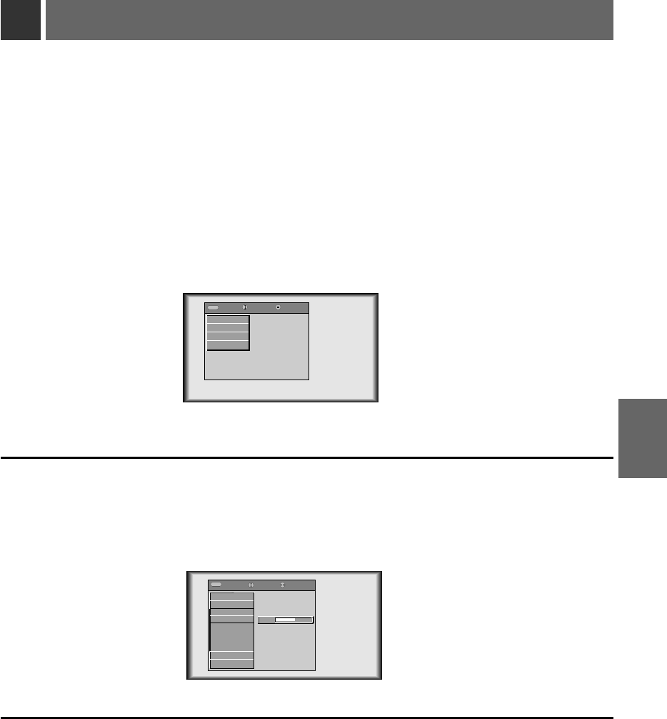
Positioning
Press the MENU button and move the POINTER button up or down to select the SPECIAL menu.
1
Press the ENTER(A)button and move the POINTER button up or down to select [Horizontal],
[Vertical] item.
*If the image size does not fit the screen in accordance with the input source, set the position of
the image by selecting Horizontal / Vertical position.
2
Press the POINTER button and move the button left or right or press the VOLUME (+, -) button to
adjust the screen condition as you want.
●
[Horizontal], [Vertical] are adjusted from -50 to +50.
●
To exit the menu display, press the MENU button.
3
< RGB mode >
exit move enter
MenuMenu
G
VIDEO
G
SPECIAL
G
TRACKING
G
AUDIO
exit move adjust
MenuMenu
G
VIDEO
E
SPECIAL
Language
Horizontal
Vertical
ARC
Zoom
Lamp Time
Set ID
G
TRACKING
G
AUDIO
0
33
SPECIAL
FUNCTIONS
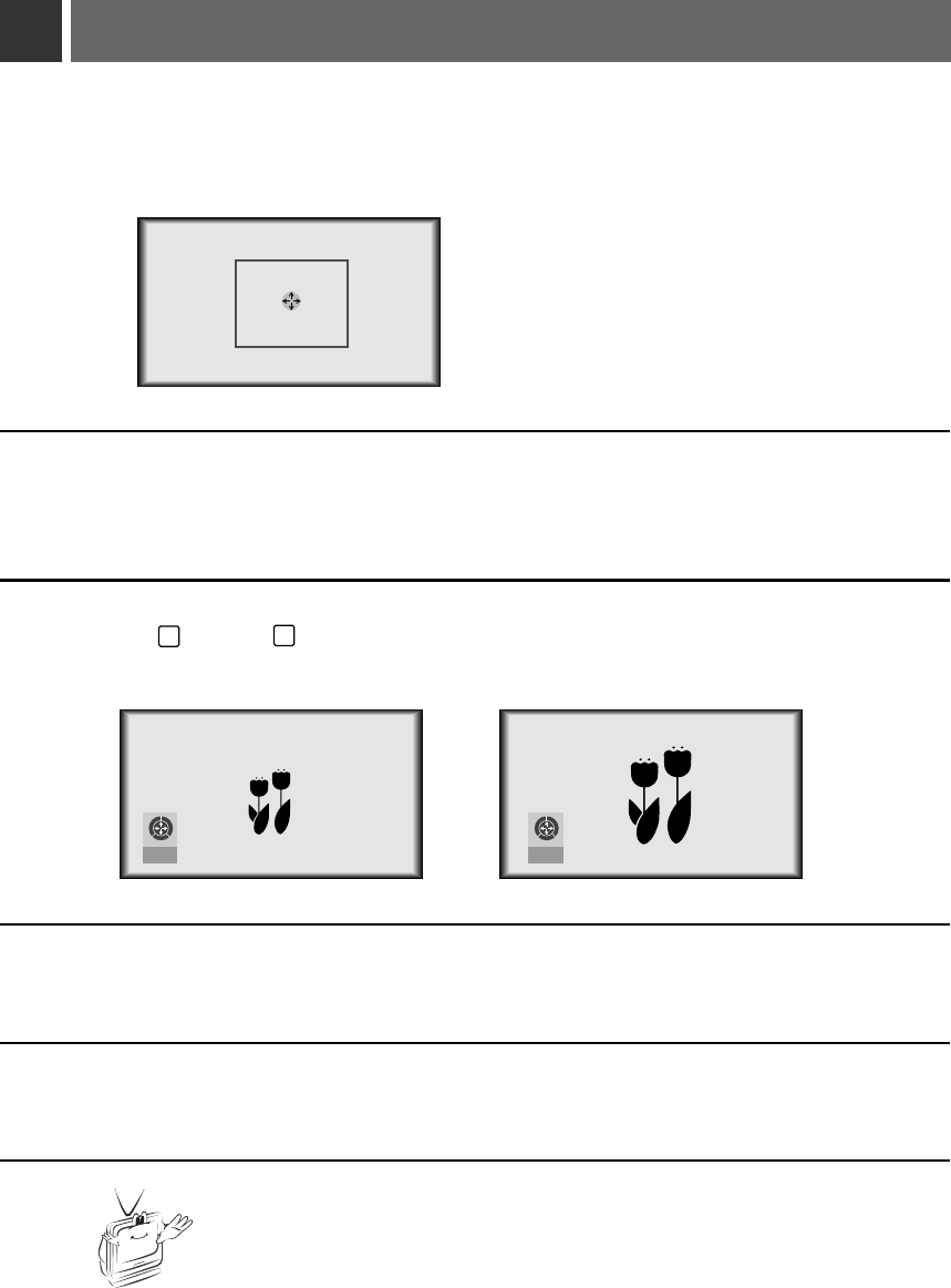
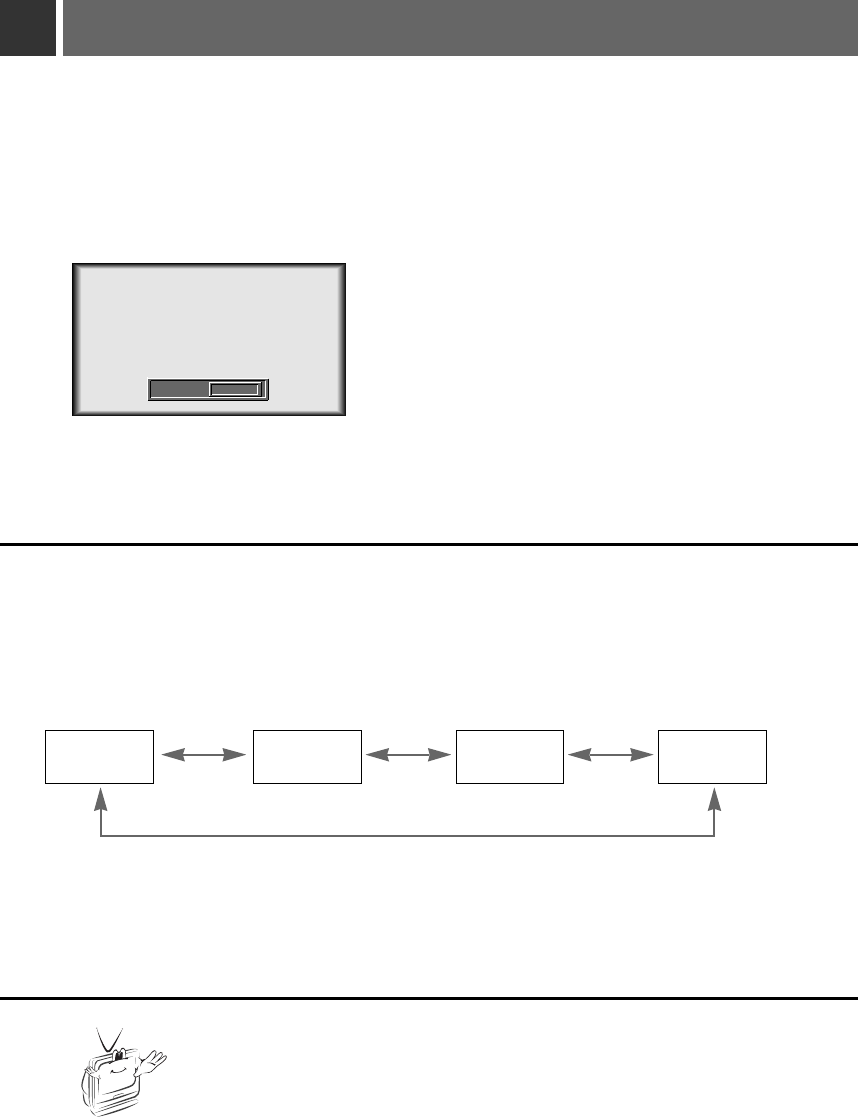
Using Zoom function
Press the ZOOM button.
1
Move to the position you want to see the enlarged screen by moving the POINTER button
left,right,up, or down.
4
Press the ZOOM or ARC or AUTO button to finish the zoom function.
5
Press the L MOUSE, R MOUSE button to adjust the zoom level.
3
* This function doesn’t work in 720p, 1080i mode.
* You can use this function by using the MENU button.
* In the zoom mode, you can adjust horizontal / vertical position with the POINTER
button.
LR
11/15
LR
15/15
34
* This function works only in PC mode.
Move the POINTER button to move the rectangular zooming area and press the ENTER or
ZOOM button to zoom into the target area.
2
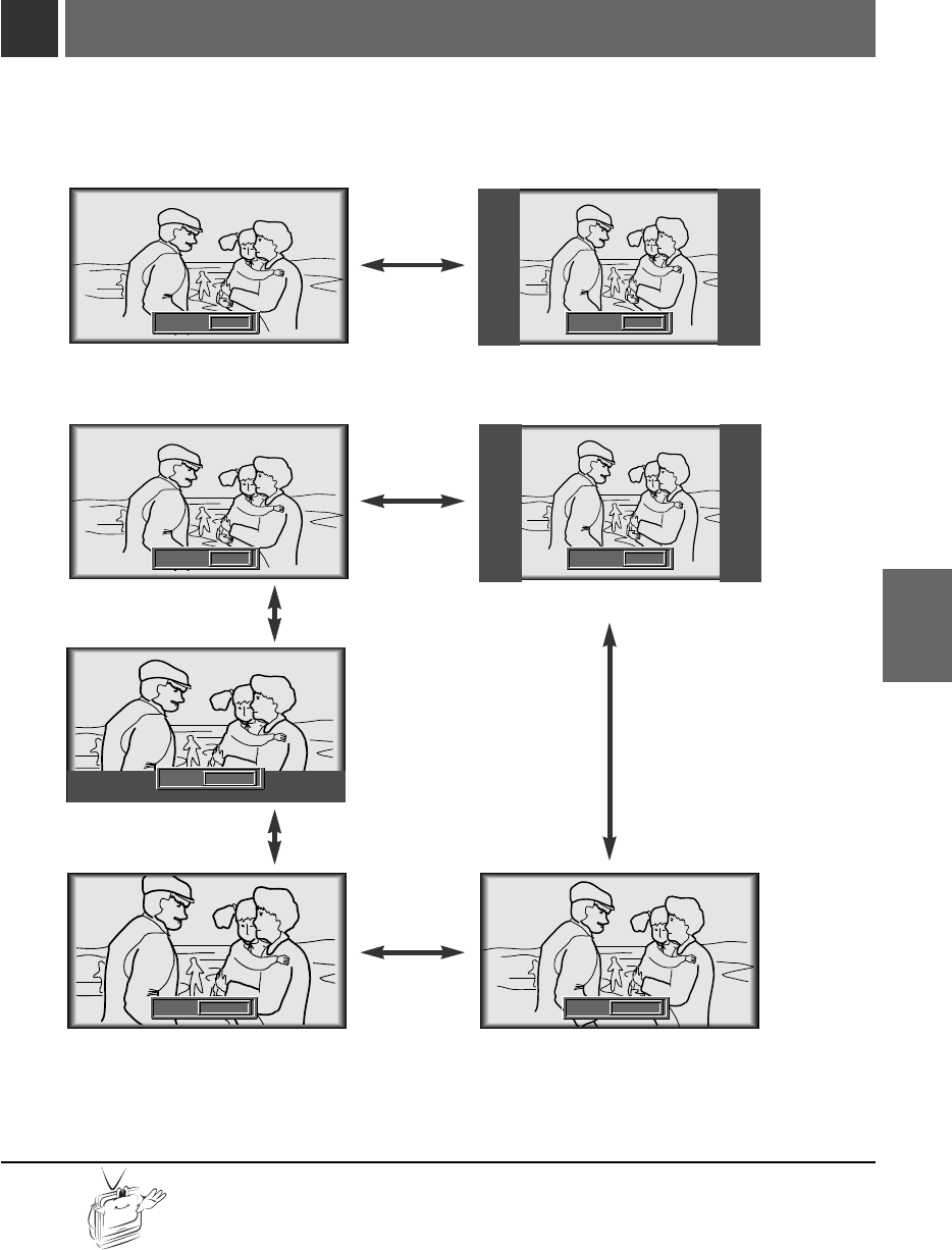
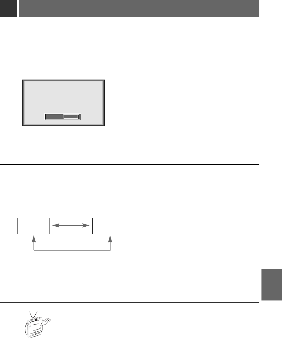
Using ARC function
* With HD input (720p,1080i) mode, you can select 16:9 picture format only.
* [Zoom2]: Choose when you want to view the center screen with disappearing black bars, with 2.35:1 formatted DVDs.
* [Zoom3]: Choose when you want to view the picture with showing little black bar, with 2.35:1 formatted DVDs. Useful for
viewing the caption.
* You can also use this function by using the MENU button.
Press the ARC button.
Each press of the button changes the display as below.
1
16:9 4 : 3
< RGB(PC) mode >
< Video/S-Video/Component mode >
ARC F16:9 GARC F4:3 G
16:9 4 : 3
ARC F16:9 G
Zoom1Zoom2
Zoom3
ARC FZoom1G
ARC
ARC F4:3 G
FZoom2G
35
SPECIAL
FUNCTIONS
Good morning.
How are you?
ARC FZoom3G
Using Tracking function
* Auto Tracking Function
This function assures you of getting the best video quality by automatically adjusting the difference of horizontal size and
synchronization of the image.
This function resets system setting if the monitor doesn’t recognize the video system in VIDEO mode.
* Image positioning and synchronization are automatically adjusted.
Press the AUTO button.
1
Adjust [Clock] or [Phase] in TRACKING menu after operation of [Auto Tracking] if you want to
get better picture quality in accordance with diverse PC input modes. (Refer to page 37.)
2
* You can also use this function by using the MENU button.(Only in RGB mode)
* For best results perform this function while displaying a still image.
Auto Tracking
Auto T
Auto Tracking Function
racking Function
36
* Clock Function
This function adjusts the horizontal width of the projected image to get the image to fit on the screen size.
* Phase Function
This function is for the detailed adjustment of the clock function.
* It’s available to adjust [Clock], [Phase] in Analog RGB mode only.
Press the MENU button and move the POINTER button up or down to select the TRACKING
menu.
1
Press the ENTER(A)button and move the POINTER button up or down to select the [Clock] or
[Phase] item.
2
Clock / Phase Function
Clock / Phase Function
Move the POINTER button left or right or press the VOLUME (+, -) button to adjust the screen con-
dition.
●
To exit the menu display, press the MENU button.
3
exit move enter
MenuMenu
G
VIDEO
G
SPECIAL
G
TRACKING
G
AUDIO
exit move adjust
MenuMenu
G
VIDEO
G
SPECIAL
E
TRACKING
Auto Tracking
Clock
Phase
G
AUDIO
25
37
TRACKING
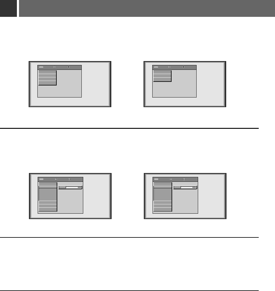
Adjusting Video
Press the MENU button and move the POINTER button up or down to select each VIDEO menu.
1
Move the POINTER button up or down to select a video item you want to adjust.
3
Move the POINTER button left or right or press the VOLUME (+, -) button to adjust the selected
video item as you want.
●
To restore the original image condition after changing it, press ENTER button after selecting
[Reset] item
(Only in RGB mode)
.
●
To finish menu display, press the MENU button.
4
Press the ENTER(A)button.
2
< RGB mode > < Video, S-Video, Component mode >
< RGB mode > < Video, S-Video, Component mode >
exit move enter
MenuMenu
G
VIDEO
G
SPECIAL
G
TRACKING
G
AUDIO
exit move adjust
MenuMenu
E
VIDEO
Contrast
Brightness
Color R
Color G
Color B
Reset
G
SPECIAL
G
TRACKING
G
AUDIO
80
exit move enter
MenuMenu
G
VIDEO
G
SPECIAL
G
AUDIO
exit move adjust
MenuMenu
E
VIDEO
Contrast
Brightness
Color
Tint
Sharpness
APC
G
SPECIAL
G
TRACKING
G
AUDIO
80
38
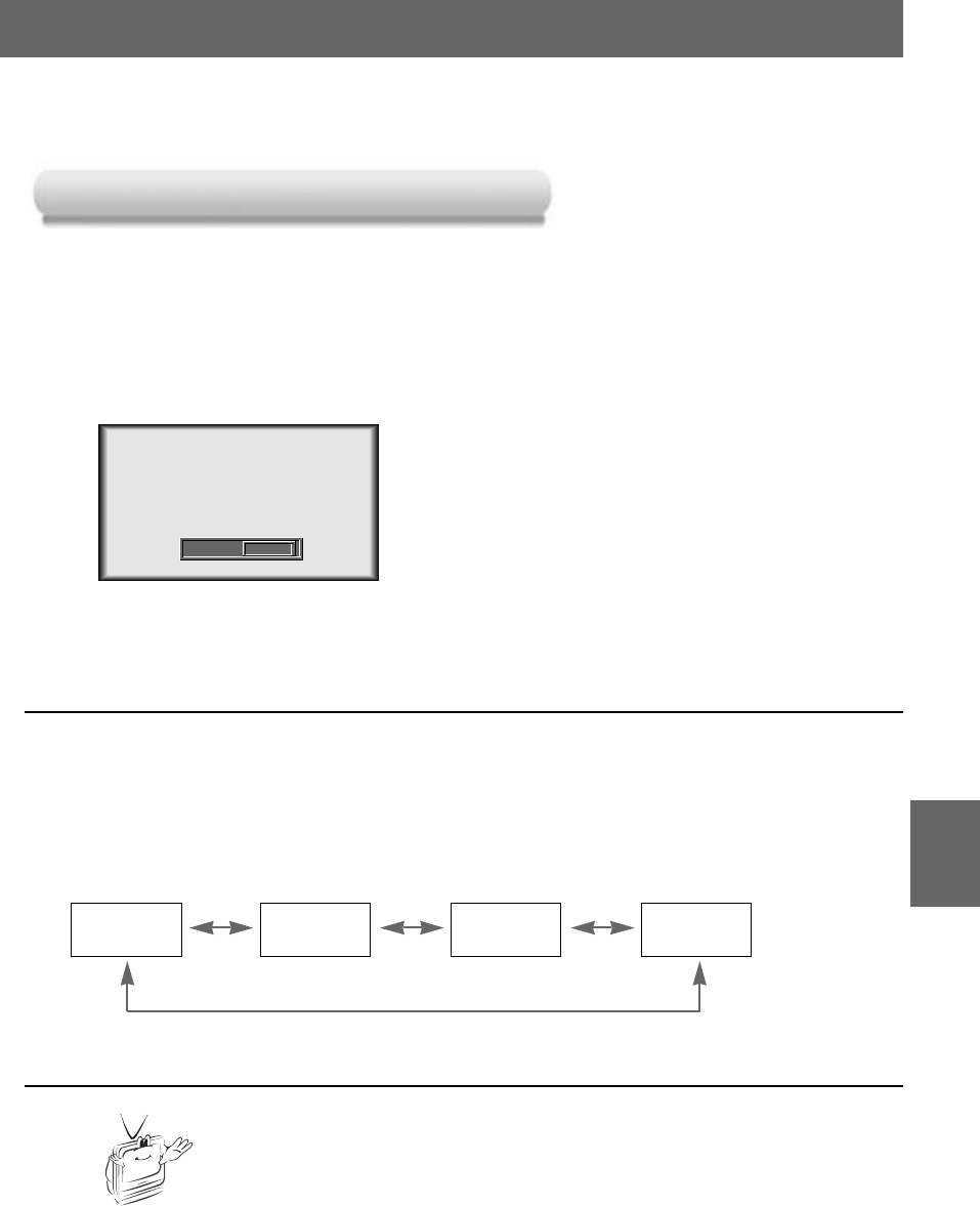
Press the APC button.
1
Each press of the APC button changes the screen as shown below.
2
User Dynamic Standard Mild
* Use APC to set the monitor for the best picture appearance.
* This function doesn’t work in RGB (PC) mode.
APC (Auto Picture Control)
APC (Auto Picture Control)
* You can also use this function by using the MENU button.
(Video/S-Video/Component mode)
APC F User G
39
VIDEO
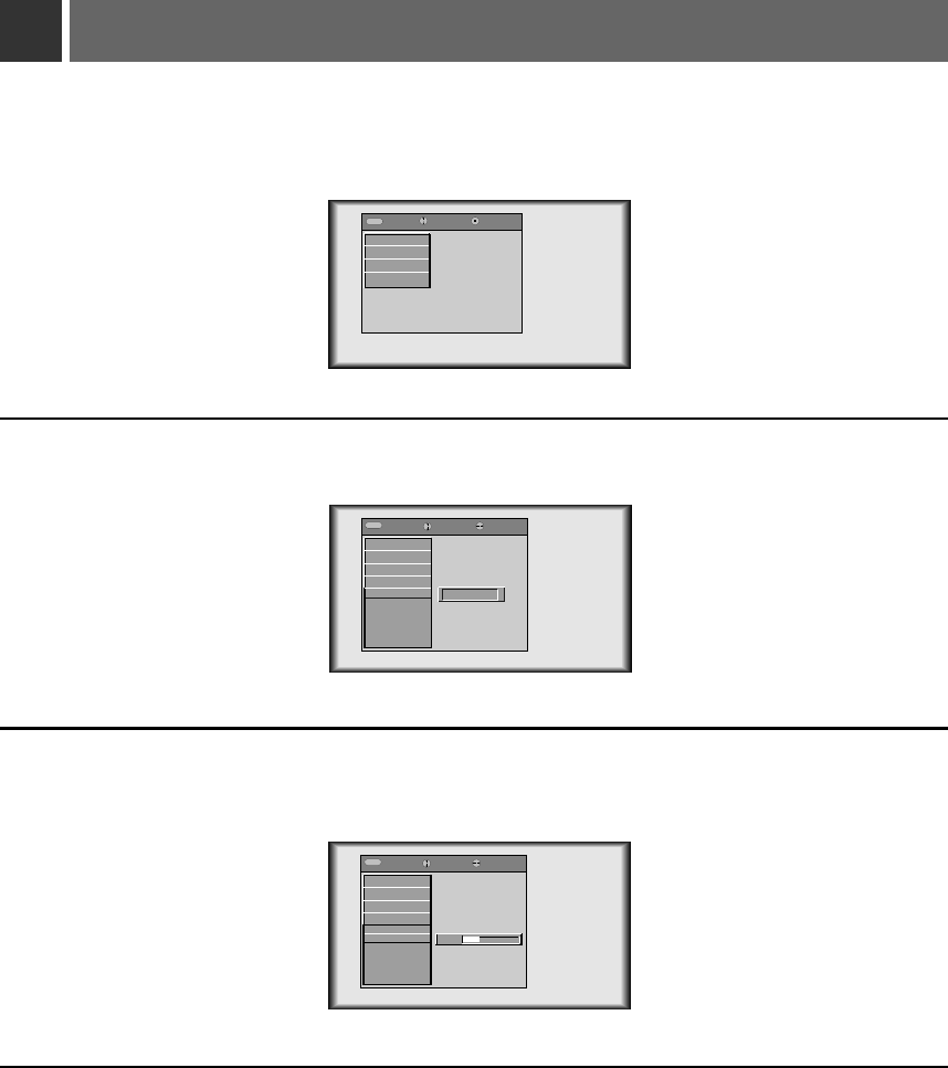
Adjusting Audio
Press the MENU button and move the POINTER button up or down to select each AUDIO menu.
1
Press the (D,E)buttons to select a audio item you want to adjust.
3
Move the POINTER button left or right or press the VOLUME (+, -) button to adjust the selected
audio condition as you want.
●
To finish menu display, press the MENU button repeatedly.
4
2
Press the ENTER(A)button
exit move enter
MenuMenu
G
VIDEO
G
SPECIAL
G
TRACKING
G
AUDIO
exit move adjust
MenuMenu
G
VIDEO
G
SPECIAL
G
TRACKING
E
AUDIO
Audio Input
Treble
Bass
Balance
DASP
AVL
20
40
exit move select
MenuMenu
G
VIDEO
G
SPECIAL
G
TRACKING
E
AUDIO
Audio Input
Treble
Bass
Balance
DASP
AVL
F
R/L
G
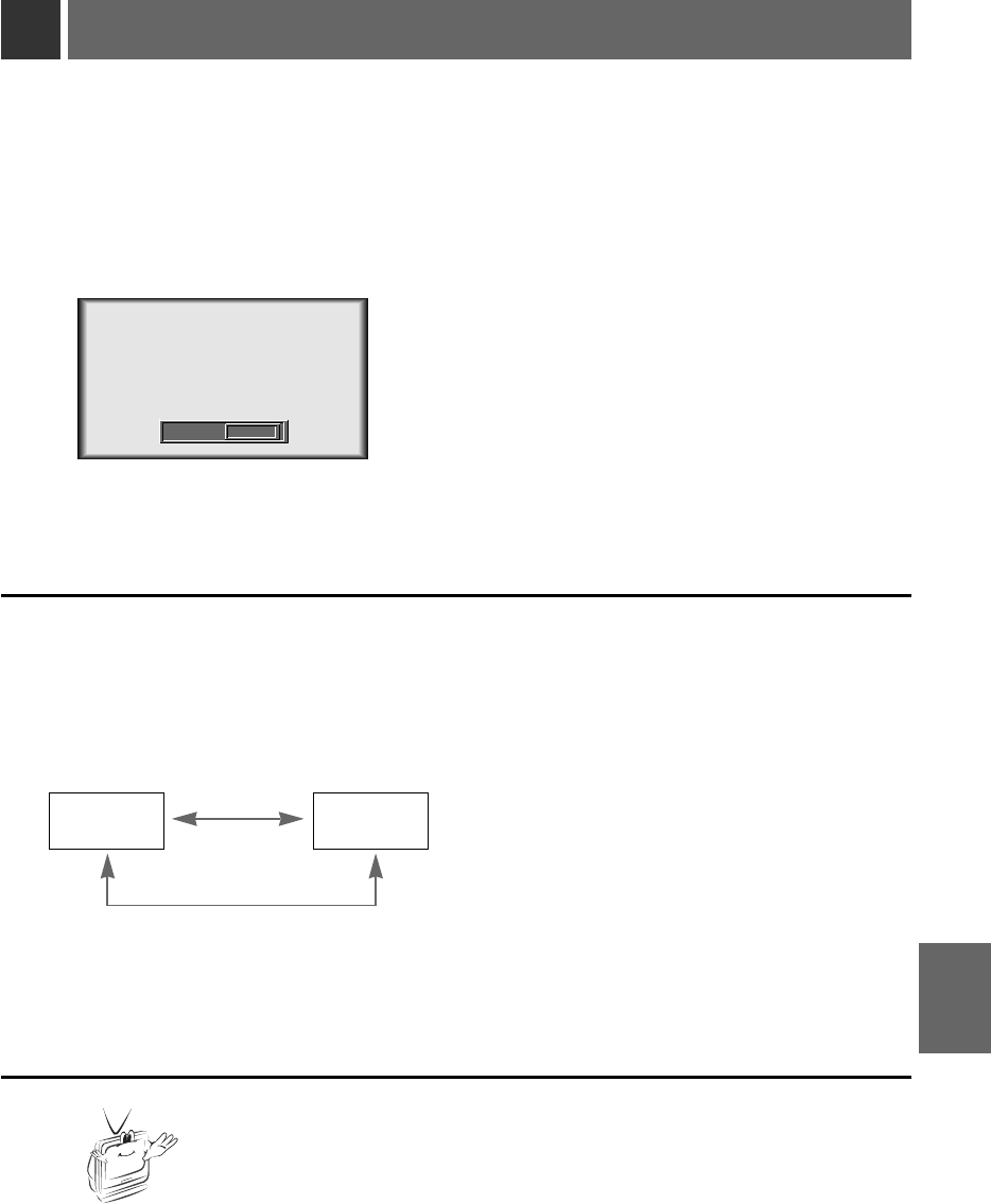
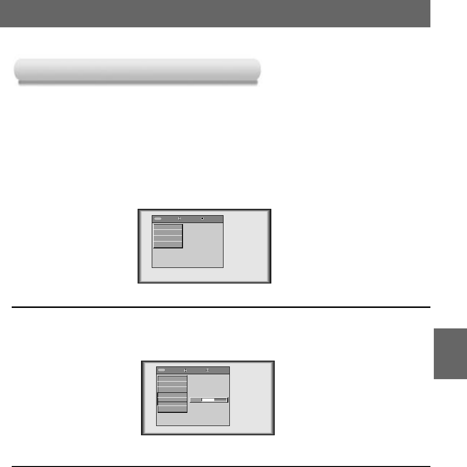
Using Audio Input function
*It’s impossible to use Audio input R/L and MIC simultaneously. This is the menu which select one of R/L(Audio
input of external equipment) and MIC(Microphone).
Press the MIC button.
1
Each press of the MIC button changes the screen as shown below.
2
R/L Mic
Audio Input F R/L G
* You can also use this function by using the MENU button.
41
AUDIO
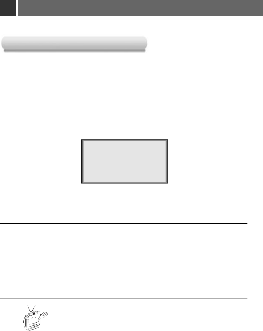
Using DASP function
Press the DASP button.
1
Each press of the DASP button changes the screen as shown below.
2
User Sports Movie Music
* You can also use this function by using the MENU button.
DASP F User G
*This function lets you enjoy the best sound without any manual adjustment because the
monitor automatically selects the appropriate audio tone levels based on the program content.
42
Using AVL function
Press the AVL button.
1
Each press of the AVL button changes the screen as shown below.
2
* You can also use this function by using the MENU button.
On Off
AVL F On G
*This feature maintains an equal volume level even if you change channels.
43
AUDIO
•Use this function to specify monitor ID number.
SET ID
Press the MENU button and move the POINTER button up or down to select the SPECIAL menu.
1
Press the ENTER(A)button and move the POINTER button up or down to select the [Set ID].
2
Move the POINTER button left or right to adjust Set ID to choose the desired monitor ID number.
●
The adjustment range of Set ID is 1~99.
●
If monitor have specified ID number, the choosed monitor operates only.
●
To exit the menu display, press the MENU button.
3
exit move enter
MenuMenu
G
VIDEO
G
SPECIAL
G
TRACKING
G
AUDIO
exit move select
MenuMenu
G
VIDEO
E
SPECIAL
Language
Horizontal
Vertical
ARC
Zoom
Lamp Time
Set ID
G
TRACKING
G
AUDIO
1
External control device setup
*
Connect the RS-232C input jack to an external control device (such as a computer or an A/V control system)
and control the Monitor’s functions externally.
*When you connect a control(RS-232C) cable to this monitor, use a control cable with a ferrite core attached.
If you do not do this, this monitor will not conform to mandatory CISPR22(EN55022) standards.
44
45
RS-232C
•Connect the serial port of the PC to the RS-232C jack on the monitor back panel.
• RS-232C cable is not supplied with the Monitor.
How to connect external control equipment
RGB IN1 RGB IN2 RGB OUT
MOUSE
RS-232CRGB IN3(DVI-I)
R L
YP
B
P
R
PONENT
COM
VIDEOS-VIDEO
DC OUT
(12V/0.5A) MIC
3
2
5
4
6
7
8
Female
(-)
RXD
TXD
GND
DTR
DSR
RTS
CTS
TXD
RXD
GND
DTR
DSR
RTS
CTS
Female
(-)
* 1, 9 Pin No Connection
<Fig.1, RS-232 Interface Cable>
2
3
5
4
6
7
8
•Use the RS232C cable to control the monitor externally (Refer to Fig.1).
Communication Parameter Setup
•Baud Rate : 19200 bps(UART)
• Data Length : 8 bits
• Parity : none
• Stop bit : 1 bit
• Flow Control : none
•Function, Arrows, and keys act as : Terminal keys
•Back space key sends : Ctrl + H
• Emulation : ANSIW
• Telnet Terminal ID : VT100
• Back Scroll buffer lines : 500
• ASCII Sending
Send Line ends with line feeds
Echo typed characters locally
Line delay : 0 ms
Character delay : 0 ms
• ASCII Receiving
Append Line feeds to incoming line ends
Force incoming data to 7-bit ASCII
Wrap lines that exceed terminal width
✓
✓
✓
Command Reference List
External control device setup
46
1. Transmission
* [Command 1] : To classify factory adjustment mode or user adjustment mode.(ASCII code, 1 Character)
* [Command 2-1] : Group classification code to control set.(ASCII code, 1 Character)
➜ Shortening Key Group :0, Video Group : 3. Audio Group:5, PIP Group :7, Others : 9
* [Command 2-2] : To control monitor set.
* [Set ID] : You can adjust the set ID to choose desired monitor ID number in special menu. See previous page.
Adjustment range is 1 ~ 99. When selecting Set ID ‘0’, every connected monitor set is controlled.
* [DATA] : To transmit command data. Transmit 2 character when organized ASCII code.
* Transmit ‘FF’ data to read status of command.
* [Cr] : Carriage Return
ASCII code ‘0x0D’
ENTER Key
* [ ] : ASCII code character correspond to “Space Bar” which is in order to classify command set ID and Data.
[Command1][Command2-1][Command2-2][ ][Set ID][ ][Data][Cr]
*The Monitor transmits ACK (acknowledgement) based on this format when receiving normal data. At this time, if the data is
data read mode, it indicates present status data. If the data is data write mode, it returns the data of the PC computer.
[Command2-1][Command2-2][ ][Set ID][ ][OK][Data][X]
[Command2-1][Command2-2][ ][Set ID][ ][NG][Data][X]
2. Error Acknowledge
*The Monitor transmits ACK (acknowledgement) based on this format when receiving abnormal data from non-viable functions
or communication errors.
Data : [01] : illegal code(This command is not supported.)
[02] : not support function(This function doesn’t work.)
[03] : wait more time(Try again a few ninute later.)
❑ Communication Protocol
Command1 Command2-1 Command2-2 SET ID Data(Hexa) Data(Hexa)
01. Power k 0 0 00 ~ 63 00, 01
02. Input Select k 0 1 00 ~ 63 00~05
03. Aspect Ratio k 0 2 00 ~ 63 00~02
04. Screen Mute k 0 3 00 ~ 63 00, 01
05. Volume Mute k 5 4 00 ~ 63 00, 01
06. Volume Control k 5 0 00 ~ 63 00~64
07. Contrast k 3 0 00 ~ 63 00~64
08. Brightness k 3 1 00 ~ 63 00~64
09. Color k 3 2 00 ~ 63 00~64
10. Tint k 3 3 00 ~ 63 00~64
11. Sharpness k 3 4 00 ~ 63 00~64
12. OSD select k 9 0 00 ~ 63 00, 01
13. Remote Control lock k 9 1 00 ~ 63 00, 01
14. Treble k 5 1 00 ~ 63 00~64
15. Bass k 5 2 00 ~ 63 00~64
16. Balance k 5 3 00 ~ 63 00~64
17. Color R k 3 6 00 ~ 63 00~64
18. Color G k 3 7 00 ~ 63 00~64
19. Color B k 3 8 00 ~ 63 00~64
47
RS-232C
01. Power (Command2-1:0, Command2-2:0)
➜To control Power On/Off of the Monitor.
Transmission
Data 00 : Power Off
01 : Power On
[k] [0] [0] [Set ID] [ ] [Data] [Cr]
[k] [0] [0] [ ] [Set ID] [ ] [FF] [Cr]
[0] [0] [ ] [Set ID] [ ] [OK] [Data] [X]
[0] [0] [ ] [Set ID] [ ] [OK] [Data] [X]
Ack
Ack
Data 00 : Power Off
01 : Power On
➜To show Power On/Off.
Transmission
Data 00 : Power Off
01 : Power On
*In like manner, if other functions transmit
‘FF’ data based on this format,
Acknowledgement data feed back presents
status about each function.
02. Input Select (Command2-1:0, Command2-2:1)
➜To select input source for the Monitor.
Transmission
Data 00 : RGB1 01 : RGB2 02 : RGB3
03 : Video 04 : S-Video 05 : Component
Data 00 : RGB1 01 : RGB2 02 : RGB3
03 : Video 04 : S-Video 05 : Component
[k] [0] [1] [ ] [Set ID] [ ] [Data] [Cr]
[0] [1] [ ] [Set ID] [ ] [OK] [Data] [X]
Ack
03. Aspect Ratio (Command2-1:0, Command2-2:2)
➜To adjust the screen format.
Transmission
Data 00 : Wide screen (16:9)
01 : Normal screen (4:3)
02 : Full screen (Zoom 1)
03 : Zoom 2
04 : Zoom 3
Data 00 : Wide screen (16:9)
01 : Normal screen (4:3)
02 : Full screen (Zoom 1)
03 : Zoom 2
04 : Zoom 3
[k] [0] [2] [ ] [Set ID] [ ] [Data] [Cr]
[0] [2] [ ] [Set ID] [ ] [OK] [Data] [X]
Ack
* Using the PC input, you select either 16:9 or 4:3 screen
aspect ratio.
04. Screen Mute (Command2-1:0, Command2-2:3)
➜To select screen mute on/off.
Transmission
Data 01 : Screen Mute On (Picture Off)
00 : Screen Mute Off (Picture On)
Data 01 : Screen Mute On (Picture Off)
00 : Screen Mute Off (Picture On)
[k] [0] [3] [ ] [Set ID] [ ] [Data] [Cr]
[0] [3] [ ] [Set ID] [ ] [OK] [Data] [X]
Ack
05. Volume Mute (Command2-1:5, Command2-2:4)
➜To control volume mute on/off.
Transmission
Data 00 : Volume Mute On (Volume Off)
01 : Volume Mute Off (Volume On)
Data 00 : Volume Mute On (Volume Off)
01 : Volume Mute Off (Volume On)
[k] [5] [4] [ ] [Set ID] [ ] [Data] [Cr]
[5] [4] [ ] [Set ID] [ ] [OK] [Data] [X]
Ack
External control device setup
48
07. Contrast (Command2-1:3, Command2-2:0)
➜To adjust screen contrast.
Transmission
Data Min : 00 ~ Max : 64
* Refer to ‘Real data mapping 1’.
Data Min : 00 ~ Max : 64
[k] [3] [0] [ ] [Set ID] [ ] [Data] [Cr]
[3] [0] [ ] [Set ID] [ ] [OK] [Data] [X]
Ack
08. Brightness (Command2-1:3, Command2-2:1)
➜To adjust screen brightness.
Transmission
Data Min : 00 ~ Max : 64
* Refer to ‘Real data mapping 1’.
Data Min : 00 ~ Max : 64
[k] [3] [1] [ ] [Set ID] [ ] [Data] [Cr]
[3] [1] [ ] [Set ID] [ ] [OK] [Data] [X]
Ack
09. Color (Command2-1:3, Command2-2:2)
➜To adjust the screen color.
Transmission
Data Min : 00 ~ Max : 64
* Refer to ‘Real data mapping 1’.
Data Min : 00 ~ Max : 64
[k] [3] [2] [ ] [Set ID] [ ] [Data] [Cr]
[3] [2] [ ] [Set ID] [ ] [OK] [Data] [X]
Ack
10. Tint (Command2-1:3, Command2-2:3)
➜To adjust the screen tint.
Transmission
Data Min : 00 ~ Max : 64
* Refer to ‘Real data mapping2’.
Data Min : 0 ~ Max : 64
* This is a Hexadecimal number data.
[k] [3] [3] [ ] [Set ID] [ ] [Data] [Cr]
[3] [3] [ ] [Set ID] [ ] [OK] [Data] [X]
Ack
* Real data mapping 1
0: Step 0
A: Step 10
F : Step 15
10 : Step 16
64 : Step 100
* Real data mapping 2
0 : Step -50
32 : Step 0
64 : Step 50
11. Sharpness (Command2-1:3, Command2-2:4)
➜To adjust the screen sharpness.
Transmission
Data Min : 00 ~ Max : 64
* Refer to ‘Real data mapping 1’.
Data Min : 00 ~ Max : 64
[k] [3] [4] [ ] [Set ID] [ ] [Data] [Cr]
[3] [4] [ ] [Set ID] [ ] [OK] [Data] [X]
Ack
12. OSD Select (Command2-1:9, Command2-2:0)
➜To select OSD (On Screen Display) On/Off.
Transmission
Data 00 : OSD Off
01 : OSD On
Data 00 : OSD Off
01 : OSD On
[k] [9] [0] [ ] [Set ID] [ ] [Data] [Cr]
[9] [0] [ ] [Set ID] [ ] [OK] [Data] [X]
Ack
06. Volume Control (Command2-1:5, Command2-2:0)
➜To adjust volume.
Transmission
Data Min : 00 ~ Max : 64
* Refer to ‘Real data mapping 1’.
Data Min : 00 ~ Max : 64
[k] [5] [0] [ ] [Set ID] [ ] [Data] [Cr]
[5] [0] [ ] [Set ID] [ ] [OK] [Data] [X]
Ack
49
RS-232C
14. Treble (Command2-1:5, Command2-2:1)
➜To adjust treble.
Transmission
Data Min : 00 ~ Max : 64
* Refer to ‘Real data mapping 1’.
Data Min : 00 ~ Max : 64
[k] [5] [1] [ ] [Set ID] [ ] [Data] [Cr]
[5] [1] [ ] [Set ID] [ ] [OK] [Data] [X]
Ack
15. Bass (Command2-1:5, Command2-2:2)
➜To adjust bass.
Transmission
Data Min : 00 ~ Max : 64
* Refer to ‘Real data mapping 1’.
Data Min : 00 ~ Max : 64
[k] [5] [2] [ ] [Set ID] [ ] [Data] [Cr]
[5] [2] [ ] [Set ID] [ ] [OK] [Data] [X]
Ack
16. Balance (Command2-1:5, Command2-2:3)
➜To adjust balance.
Transmission
Data Min : 00 ~ Max : 64
* Refer to ‘Real data mapping 2’.
Data Min : 00 ~ Max : 64
[k] [5] [3] [ ] [Set ID] [ ] [Data] [Cr]
[5] [3] [ ] [Set ID] [ ] [OK] [Data] [X]
Ack
13. Remote Control lock
(Command2-1:9, Command2-2:1)
➜To lock the front panel controls on the
monitor and remote control.
Transmission
Data 00 : Lock Off
01 : Lock On
Data 00 : Lock Off
01 : Lock On
[k] [9] [0] [ ] [Set ID] [ ] [Data] [Cr]
[9] [0] [ ] [Set ID] [ ] [OK] [Data] [X]
Ack
* If you’re not use the remote control, set this mode. 17. Color R Adjustment
(Command2-1:3, Command2-2:6)
➜ To adjust red in color temperature.
Transmission
Data Min : 00 ~ Max : 64
* Refer to ‘Real data mapping 1’.
Data Min : 00 ~ Max : 64
[k] [3] [6] [ ] [Set ID] [ ] [Data] [Cr]
[3] [6] [ ] [Set ID] [ ] [OK] [Data] [X]
Ack
18. Color G Adjustment
(Command2-1:3, Command2-2:7)
➜ To adjust green in color temperature.
Transmission
Data Min : 00 ~ Max : 64
* Refer to ‘Real data mapping 1’.
Data Min : 00 ~ Max : 64
[k] [3] [7] [ ] [Set ID] [ ] [Data] [Cr]
[3] [7] [ ] [Set ID] [ ] [OK] [Data] [X]
Ack
19. Color B Adjustment
(Command2-1:3, Command2-2:8)
➜ To adjust blue in color temperature.
Transmission
Data Min : 00 ~ Max : 64
* Refer to ‘Real data mapping 1’.
Data Min : 00 ~ Max : 64
[k] [3] [8] [ ] [Set ID] [ ] [Data] [Cr]
[3] [8] [ ] [Set ID] [ ] [OK] [Data] [X]
Ack
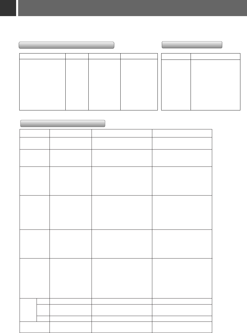
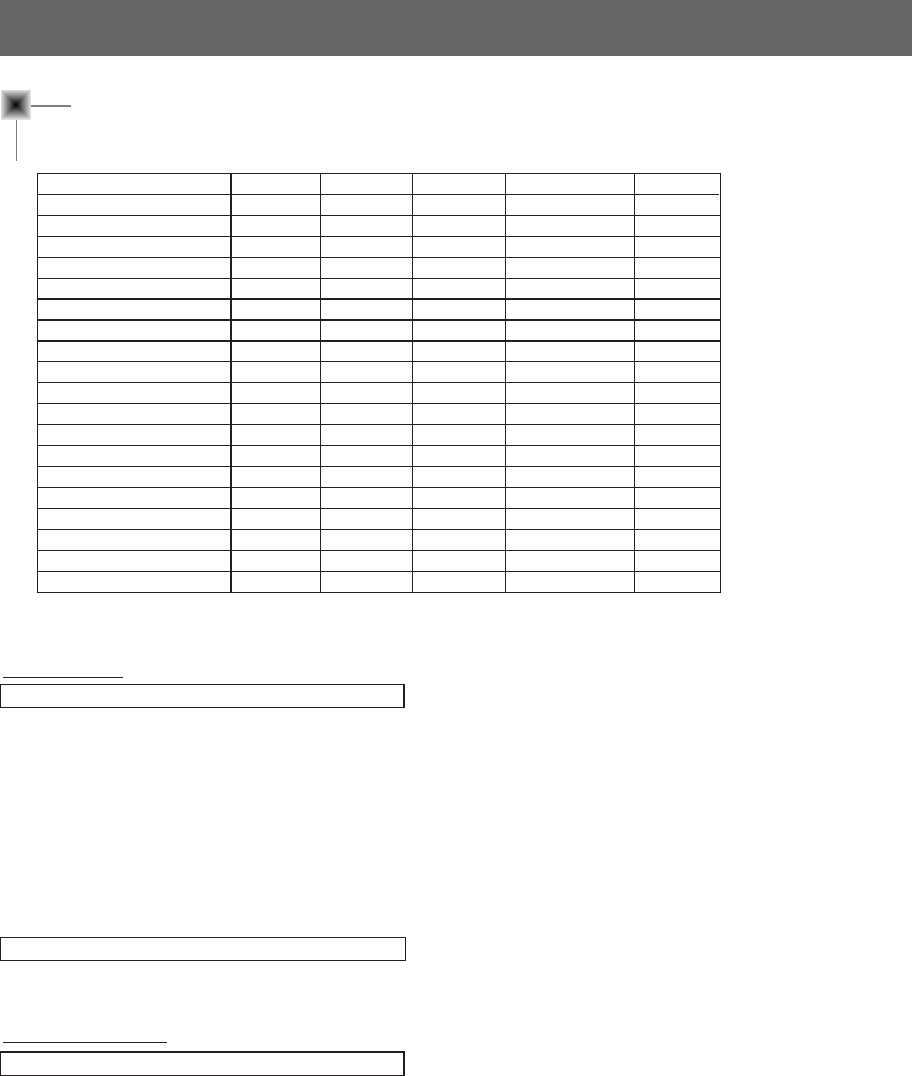
Supported Monitor Display
*The monitor displays images at a resolution of 1280x720 pixels.
To display higher resolution images(1152x864mode, 1280x1024mode), the monitor compresses it to 1280x720.
The following table lists the display formats supported by the monitor.
* If the monitor does not support the input signal, “Out of Range” message appears on the screen.
* The monitor supports DDC1/2B type as Plug & Play function.(Auto recognition of PC monitor)
* Synchronization input form : Separate, Composite
Sources Format Vertical Freq.(Hz) Horizontal Freq. (kHz)
VGAEGA 640X350 70.090Hz 31.468kHz
640X350 85.080Hz 37.861kHz
PC98 / VGA text 640X400 85.080Hz 37.861kHz
720X400 70.082Hz 31.469kHz
720X400 85.039Hz 37.927kHz
VGA 640X480 59.940Hz 31.469kHz
640X480 72.800Hz 37.861kHz
640X480 75.00Hz 37.500kHz
640X480 85.008Hz 43.269kHz
640X480 100.040Hz 53.011kHz
SVGA 800X600 56.250Hz 35.156kHz
800X600 60.317Hz 37.879kHz
800X600 72.188Hz 48.077kHz
800X600 75.00Hz 46.875kHz
800X600 85.061Hz 53.674kHz
800X600 100.00Hz 64.016kHz
XGA 1024X768 43.479Hz (interlace) 35.522kHz
1024X768 60.004Hz 48.363kHz
1024X768 70.069Hz 56.476kHz
1024X768 75.029Hz 60.023kHz
1024X768 84.997Hz 68.677kHz
SXGA 1152X864 60.053Hz 54.348kHz
1152X864 70.016Hz 63.995kHz
1152X864 75.00Hz 67.500kHz
1152X864 85.057Hz 77.487kHz
1280X960 60.00Hz 60.00kHz
1280X960 75.00Hz 75.00kHz
1280X1024 60.020Hz 63.981kHz
MAC 16
¥
832X624 74.550Hz 49.725kHz
19
¥
1024X768 60.004Hz 48.363kHz
1024X768 75.029Hz 60.241kHz
20
¥
1152X870 75.062Hz 68.681kHz
HD 1920X1080i 60.00Hz 33.750kHz
1280X720p 60.00Hz 45.00kHz
50
Video system Remarks
NTSC M 3.579545MHz/60Hz
NTSC 4.433618MHz/60Hz
PAL B, G, H, I 4.433618MHz/50Hz
PAL M 3.575611MHz/60Hz
PAL N 3.582056MHz/50Hz
SECAM 4.286MHz/50Hz
PAL 60 4.433618MHz/60Hz
Video system input signal
DVD/DTV/Component display specification
RGB image display specification
Proposed
SDTV, DVD 480i
SDTV, DVD 480i
EDTV 480p
SDTV, DVD 625 Line
HDTV 576p
HDTV 720p 60Hz
HDTV 720p 59.94Hz
HDTV 1080i 50Hz
HDTV 1080i 60Hz(ATSC)
HDTV 1080i 59.94Hz
Format
640X480
640X480
704X480
720X576
720X576
1280X720
1280X720
1920X1080
1920X1080
1920X1080
Vertical Freq.(Hz)
60Hz
59.94Hz
59.94Hz
50.00Hz
50.00Hz
60.00Hz
59.94Hz
50.00Hz
60.00Hz
59.94Hz
Horizontal Freq.(kHz)
15.73kHz
15.63kHz
31.47kHz
15.625Hz
31.25Hz
45.00Hz
44.96Hz
31.25Hz
33.75Hz
33.72Hz
51
Specifications
MODEL
Width(mm)
Heigh(mm)
Depth(mm)
Weight(kg)
LCD panel size
Resolution
MW-60SZ12
1440
1080
491.5
66.75
30.734mm(1.21 inches)
1280(Horizontal) x 720(Vertical)pixel
Lamp
Operating Condition
temperature Model : AS-LA20
Power consumption : 100W
In operation : 32~104°F(0°C~40°C)
In storage and transit : -4~140°F(-20°C~60°C)
humidity
In operation : 30 ~ 80% relative humidity by dry hygrometer
Not in operation : 30 ~ 90% relative humidity by dry hygrometer
P/NO : 3828VA0349A b (373-026H)
MW-60SZ12
OWNER’S MANUAL
LCD PROJECTION MONITORLCD PROJECTION MONITOR
Please read this manual carefully before operating
your set.
Retain it for future reference.
Record model number and serial number of the set.
See the label attached on the back of the set and
quote this information to your dealer when you
require service.
Model number :
Serial number :