LG Electronics USA N1910LZT LED LCD MONITOR User Manual EMISSION TEST REPORT
LG Electronics USA LED LCD MONITOR EMISSION TEST REPORT
Users Manual

Order Number
: GETEC-C1-11-046
FCC Part 15 subpart B
Test Report Number
: GETEC-E3-11-016
Page 1 / 1
EUT Type: LED LCD Monitor
FCC ID.: BEJN1910LZT
APPENDIX G
: USER’S MANUAL

www.lg.com
User Manual
NETWORK MONITOR
N1910LZ
Please read the safety information carefully before using the product.
Network Monitor Model(s)
English

2
ENG
English
Table of Contents
TABLE OF CONTENTS
3 ASSEMBLY AND PREPARA-
TION
3 Product Components
4 Component and Button Description
6 Monitor Installation
6 - Assembling the stand base
6 - Detaching the stand base and the stand
body
7 - Adjusting the stand height
7 - Adjusting the angle
8 - Pivot feature
9 - Installing on a table
9 - Using the Kensington locking device
10 - Detaching the stand base and the stand
body
10 - Installing the wall mount plate
11 - Installing on a wall
12 USING THE MONITOR
12 Connecting Input Signal Cable
12 - D-SUB connection
13 - DVI connection - PCoIP
14 Connecting LAN/Peripherals
14 LAN connection - PCoIP
15 - Peripheral device connection
16 - Self Image Adjustment
17 USER CONFIGURATION
17 Activating the Main Menu
18 MENU Settings
18 - Picture
19 - Color
20 - Display
21 - Others
22 MODE Settings
22 - F-ENGINE
23 - PHOTO EFFECT
24 AUTO Settings
25 TROUBLESHOOTING
27 PRODUCT SPECIFICATION
27 N1910LZ
28 Preset Mode
28 Power Indicator
29 PROPER POSTURE
29 Proper posture for using the monitor
30 USING PCOIP SOLUTION
3
ENG
English
Assembly and Preparation
ASSEMBLY AND PREPARATION
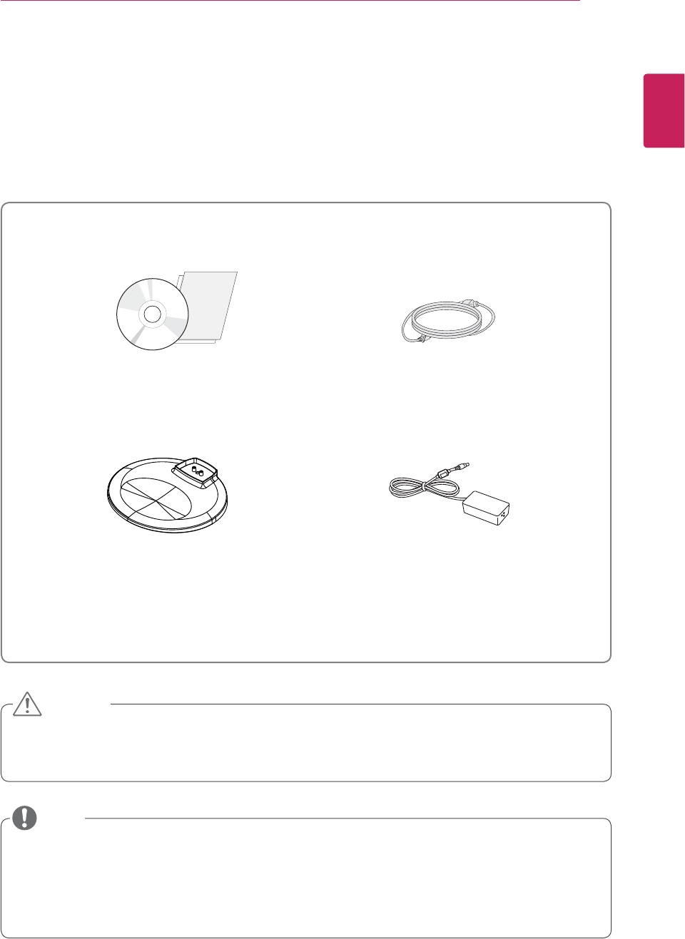
Product Components
Please check whether all the components are included in the box before using the product. If there are
missing components, contact the retail store where you purchased the product. Note that the product and
components may look different from those shown here.
y Always use genuine components to ensure safety and product life.
y The product warranty will not cover damage or injury caused by the use of counterfeit components.
y Note that the components may look different from those shown here.
y Without prior notice, all information and specifications in this manual are subject to change to improve
the performance of the product.
y To purchase optional accessories, visit an electronics store or online shopping site or contact the retail
store where you purchased the product.
Power Cord
User Manual/Card
Stand Base Adaptor
CAUTION
NOTE
4
ENG
English
Assembly and Preparation
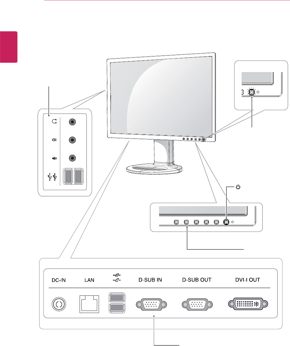
Component and Button Description
Power Indicator
y On: Power is on
y Off: Power is off
Front Side Buttons
Input Connector (See p.12 to 15)
(Power Button)
Input Connector
(See p.15 )
5
ENG
English
Assembly and Preparation
Button Description
MENU Activates the main menu.
OSD Lock/Unlock
Functions
Locks/unlocks the OSD screen.
yTo lock the OSD screen, press and hold the MENU button
for several seconds. The "OSD LOCKED" message will be
displayed and the screen will be locked.
yTo unlock the OSD screen, press and hold the MENU
button again for several seconds. The "OSD UNLOCKED"
message will be displayed and the screen will be unlocked.
MODE Moves to the F-ENGINE and PHOTO EFFECT options.
AUTO To adjust the monitor settings, press the AUTO button on the MONITOR SETUP OSD
menu (only supported for analog signal).
For optimal screen display, use the following resolution.
Optimal Resolution 1280 x 1024
INPUT Allows selection of the input signal.
yIf you connect the monitor to a computer using a D-SUB cable, select either the PCoIP
or D-SUB input signal.
yIf only one computer is connected to the monitor, the input signal is detected automati-
cally. The initial input signal is PCoIP.
EXIT Exits the OSD menu.
(Power Button)
yD-SUB Input: Power On/Off
yPCoIP Input
Monitor Off: Press the power button twice, or press the power button and wait for 10
seconds.
PCoIP Off: Press the power button, then press the EXIT button located next to the
power button.
PCoIP On: Press the power button.
Power Indicator When the monitor is in operating mode, the power indicator
will turn white (on mode).
When the monitor is in power saving mode, the power indica-
tor will blink white.
6
ENG
English
Assembly and Preparation
y The components appearing in the illustra-
tions may look different from the actual prod-
uct.
yDo not carry the monitor upside-down as this
may cause it to fall off its stand, resulting in
damage or injury.
y To avoid damaging the screen when lifting
or moving the monitor, only hold the stand or
the plastic cover. This avoids putting unnec-
essary pressure on the screen.
y Only remove the tape and the locking pin
when the monitor is mounted on the stand
base and is in an upright position. Otherwise,
the stand body may protrude, which may
lead to injury.
Detaching the stand base and the
stand body
1 Place the monitor's screen face down.
To protect the screen from scratches, cover the
surface with a soft cloth.
Monitor Installation
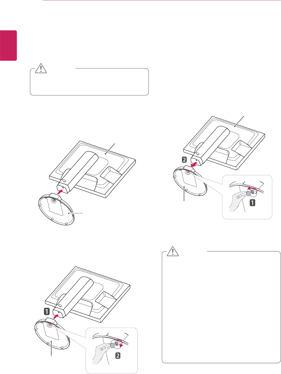
Assembling the stand base
1 Place the monitor's screen face down.
y To protect the screen from scratches, cover
the surface with a soft cloth.
3 Using a coin, turn the screw clockwise to se-
cure the stand base.
2 Check the position (at the front and rear) of
the stand body, then mount the stand base on
the stand body as shown in the figure.
Stand Body
Stand Base
Stand Base
2 Using a coin, turn the screw in the stand base
counterclockwise. Detach the stand base from
the stand body.
Stand Body
Stand Base
CAUTION
CAUTION
7
ENG
English
Assembly and Preparation
y Once the pin is removed, it is not necessary
to re-insert it to adjust the height.
Adjusting the stand height
1 Place the monitor mounted on the stand base
in an upright position.
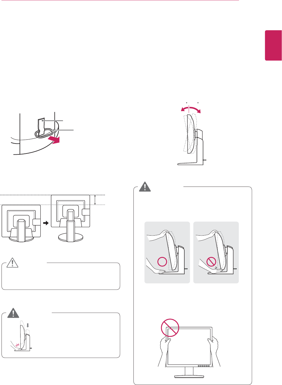
Adjusting the angle
1 Place the monitor mounted on the stand base
in an upright position.
2 Remove the tape attached at the bottom rear
of the stand body, then pull out the locking
pin.
3 The height can be adjusted up to 110 mm.
2 Adjust the angle of the screen. The angle of the
screen can be adjusted up to 15° forwards and
5° backwards for a comfortable viewing experi-
ence.
y To avoid injury to the fingers when adjusting
the screen, do not hold the lower part of the
monitor's frame as illustrated below.
yDo not put your finger be-
tween the screen and the
base (chassis) when adjust-
ing the screen's height.
y Be careful not to touch or press the screen
area when adjusting the angle of the monitor.
Front Side Rear Side
15- 5
Tape
Locking Pin
Stand Body
110.0 mm
CAUTION
WARNING
WARNING
8
ENG
English
Assembly and Preparation
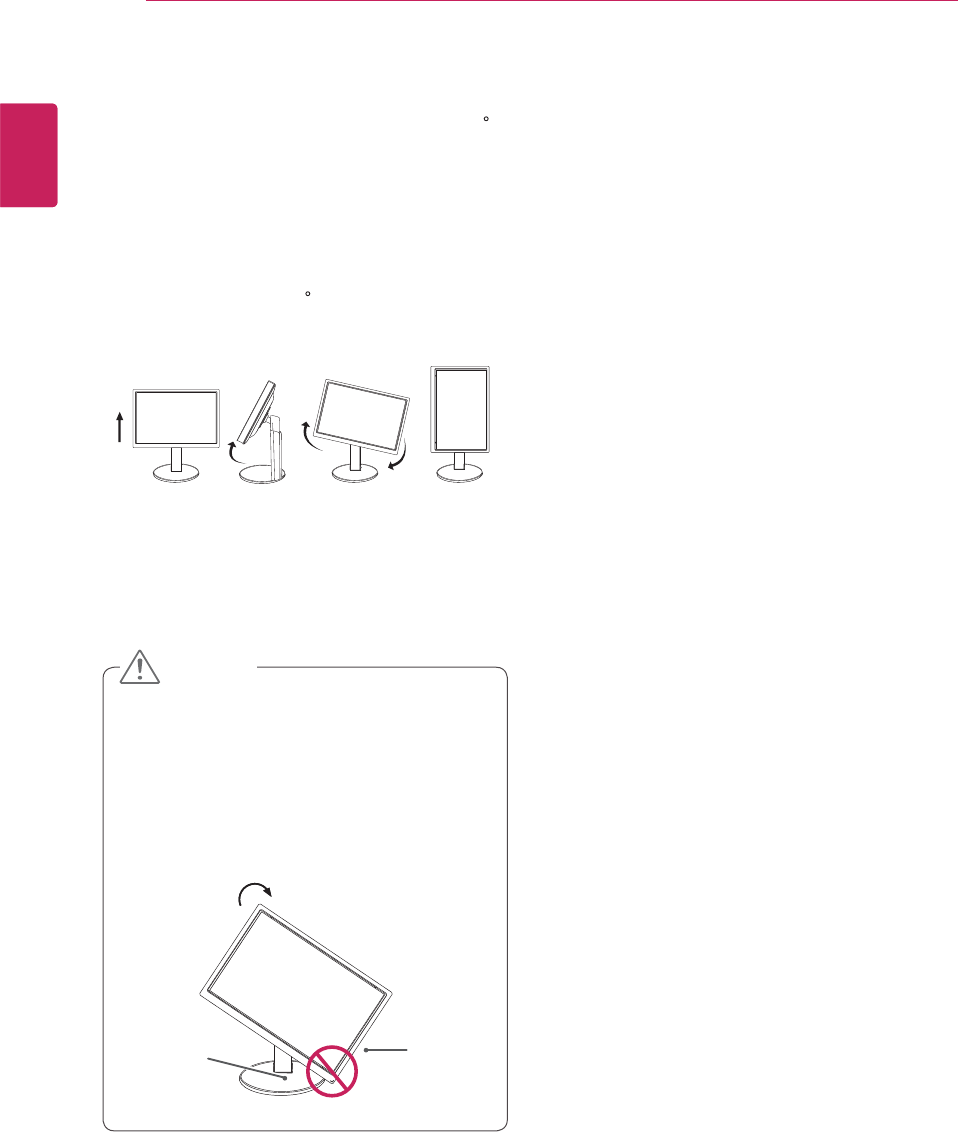
y Take care when rotating the monitor if the
cable is connected.
y To avoid scratching the stand base, make
sure that when rotating the screen using the
pivot feature, the stand does not make con-
tact with the monitor.
Pivot feature
The pivot feature allows the monitor to rotate 90
clockwise.
2 Rotate the monitor 90 clockwise as illustrated.
Head
Stand
1 Raise the monitor up to the maximum height.
CAUTION
9
ENG
English
Assembly and Preparation
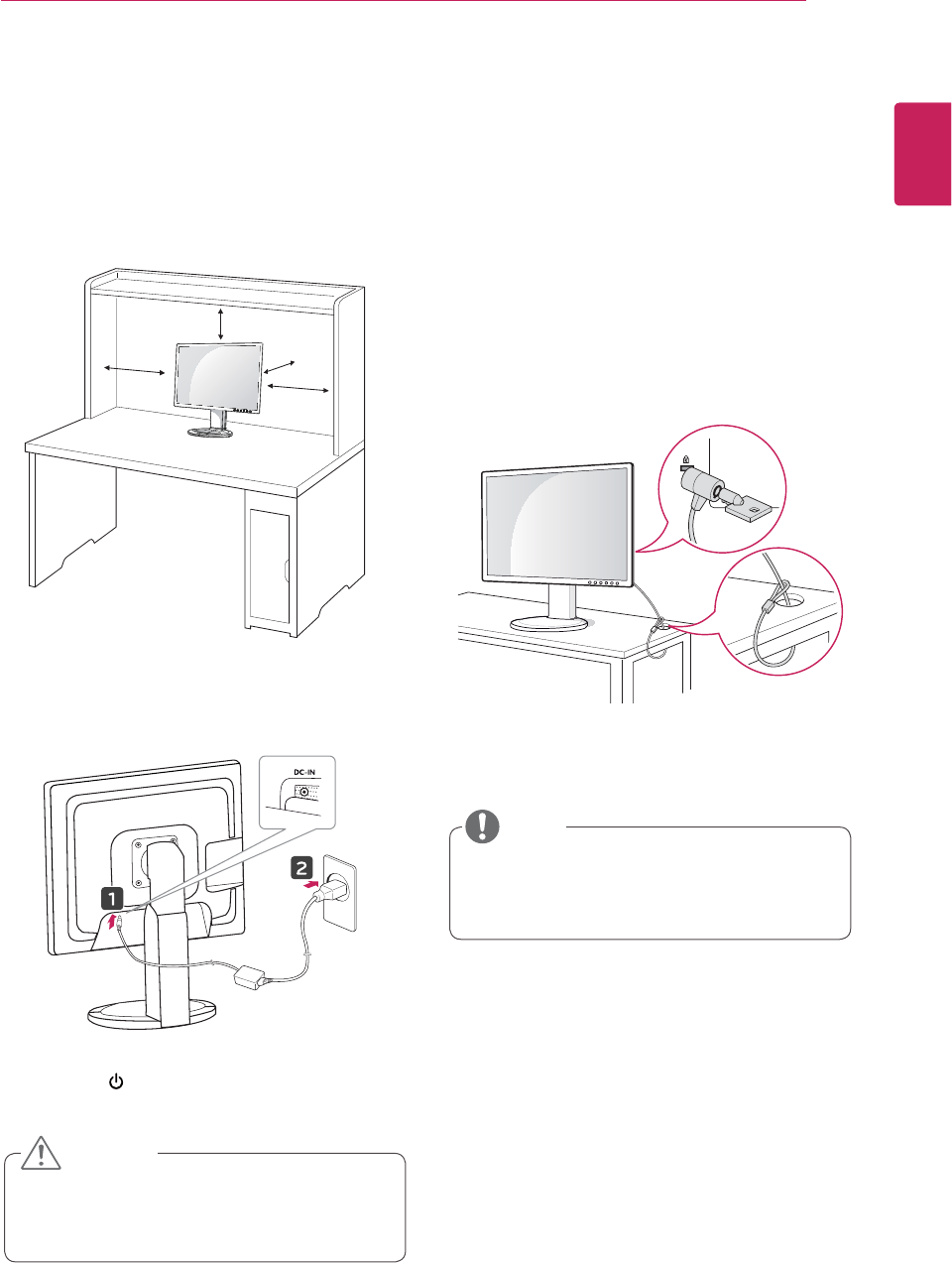
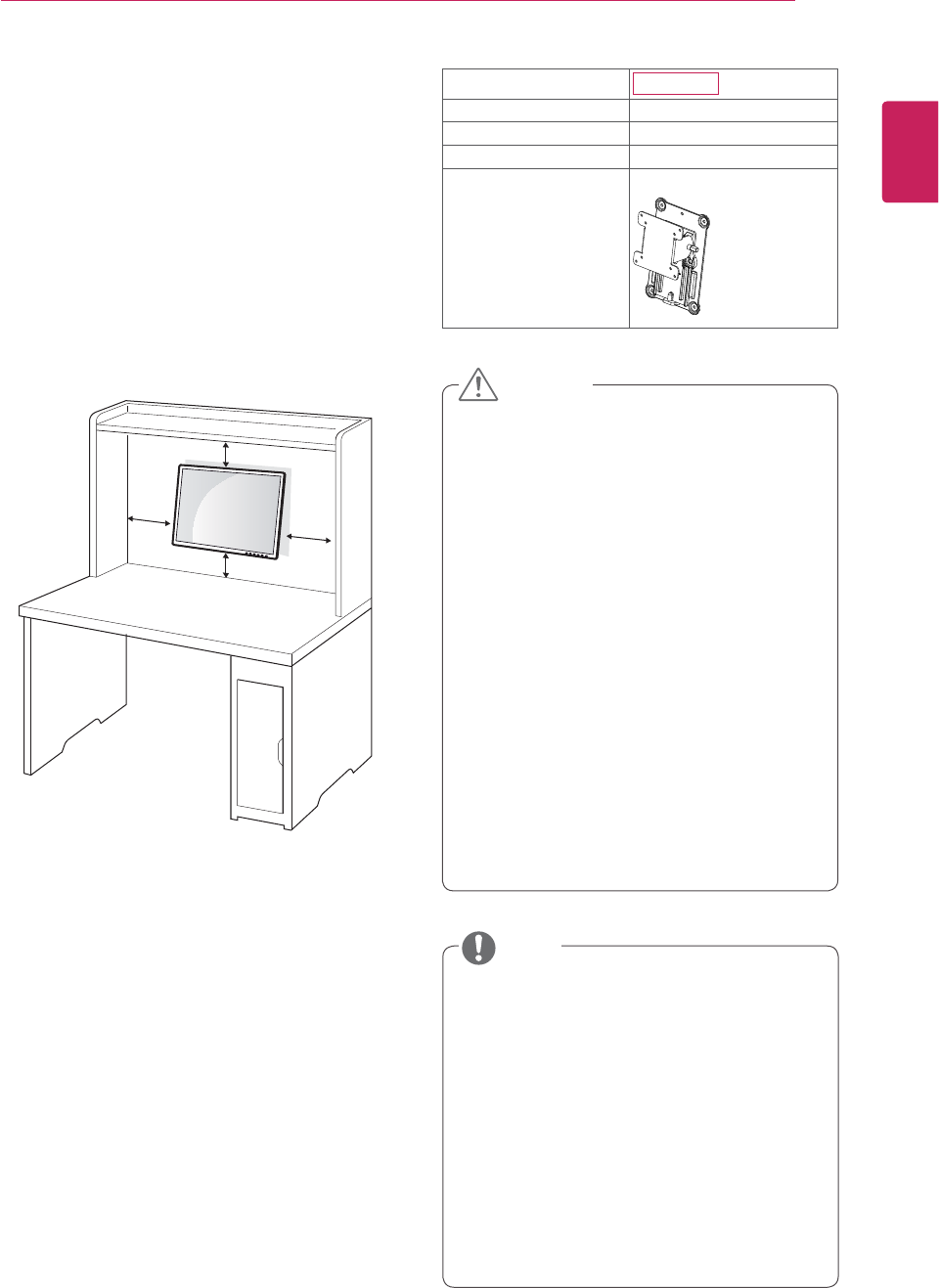
Installing on a table
1 Lift the monitor and place it on the table in an
upright position.
Install at least 10 cm away from the wall to
ensure sufficient ventilation.
2 Connect the adaptor to the monitor, then plug
the power cord into the wall outlet.
3 Press the (Power) button on the front of the
monitor to turn on the monitor.
10 cm
10 cm
10 cm
10 cm
Unplug the power cord prior to moving or
installing the monitor. There is risk of electric
shock.
Using the Kensington locking
device
The connector for the Kensington lock is located
on the rear of the monitor.
For more information on installation and usage,
refer to the Kensington lock user manual or visit
the website at http://www.kensington.com.
Connect the monitor to the table with the Kensing-
ton lock cable.
Using the Kensington lock is optional. The
accessories can be purchased at your local
electronics store.
CAUTION
NOTE
10
ENG
English
Assembly and Preparation
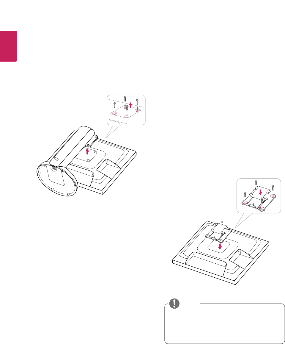
Installing the wall mount plate
This monitor supports the specification of the stan-
dard wall mount plate or compatible device.
Detaching the stand base and the
stand body
1 Place the monitor's screen face down. To
protect the screen from scratches, cover the
surface with a soft cloth.
2 Using a screwdriver, remove the four screws
and detach the stand from the monitor.
1 Place the monitor's screen face down. To
protect the screen from scratches, cover the
surface with a soft cloth.
2 Place the wall mount plate on the monitor and
align it with the screw holes on the monitor.
3 Using a screwdriver, tighten the four screws to
fix the plate onto the monitor.
y The wall mount plate is sold separately.
y For more information on the installation, refer
to the wall mount plate's installation guide.
Wall Mount Plate
NOTE
11
ENG
English
Assembly and Preparation
If you want to mount the monitor on the wall (op-
tional), attach the wall mounting bracket to the rear
of the monitor.
Make sure that the wall mounting bracket is se-
curely fixed to the monitor and to the wall.
Use the wall mount plate and screws that comply
with the VESA standard as specified below.
y 784.8 mm (30.9 inch) or less
* Thickness of the wall mount plate: 2.6 mm
* Fastening screw: Diameter 4.0 mm x Pitch 0.7
mm x
Length 10 mm
y 787.4 mm (31.0 inch) or greater
* Use the wall mount plate and screws con-
forming to the VESA standard.
yUnplug the power cord before moving or in-
stalling the monitor to avoid electric shocks.
y Installing the monitor on the ceiling or on a
slanted wall may result in the monitor falling
off, which could lead to injury. Please use
the genuine LG wall mounting bracket. For
more information, contact your local retail
store or a qualified installer.
y Applying excessive force when fastening
screws may cause damage to the moni-
tor. Damage caused in this way will not be
covered by the product warranty.
y Use the wall mounting bracket and screws
that conform to the VESA standard. Dam-
age caused by the use or misuse of inap-
propriate components will not be covered
by the product warranty.
y Use the screws specified in the VESA stan-
dard.
y The wall mount kit includes the installation
guide and necessary parts.
y The wall mounting bracket is optional. The
accessories can be purchased at your local
retail store.
y The length of the screw may differ for each
wall mounting bracket. Ensure the correct
length of the screw is used.
y For more information, please refer to the user
manual for the wall mounting bracket.
Model N1910LZ
VESA (A x B) 75 x 75
Stand Screw M4
Required Screw 4
Wall Mount Plate
(Optional)
RW120
Installing on a wall
Install the monitor at least 10 cm away from the
wall and leave about 10 cm of space at each side
of the monitor to ensure sufficient ventilation. De-
tailed installation instructions can be obtained from
your local retail store. Please refer to the manual
to install and set up a tilting wall mounting bracket.
10 cm
10 cm
10 cm 10 cm
CAUTION
NOTE
12
ENG
English
Using the Monitor
USING THE MONITOR
Connecting Input Signal Ca-
ble
y This monitor supports the *Plug and Play
feature.
*Plug and Play: A feature that allows you to
add a device to your computer, without having
to reconfigure anything or install any manual
drivers.
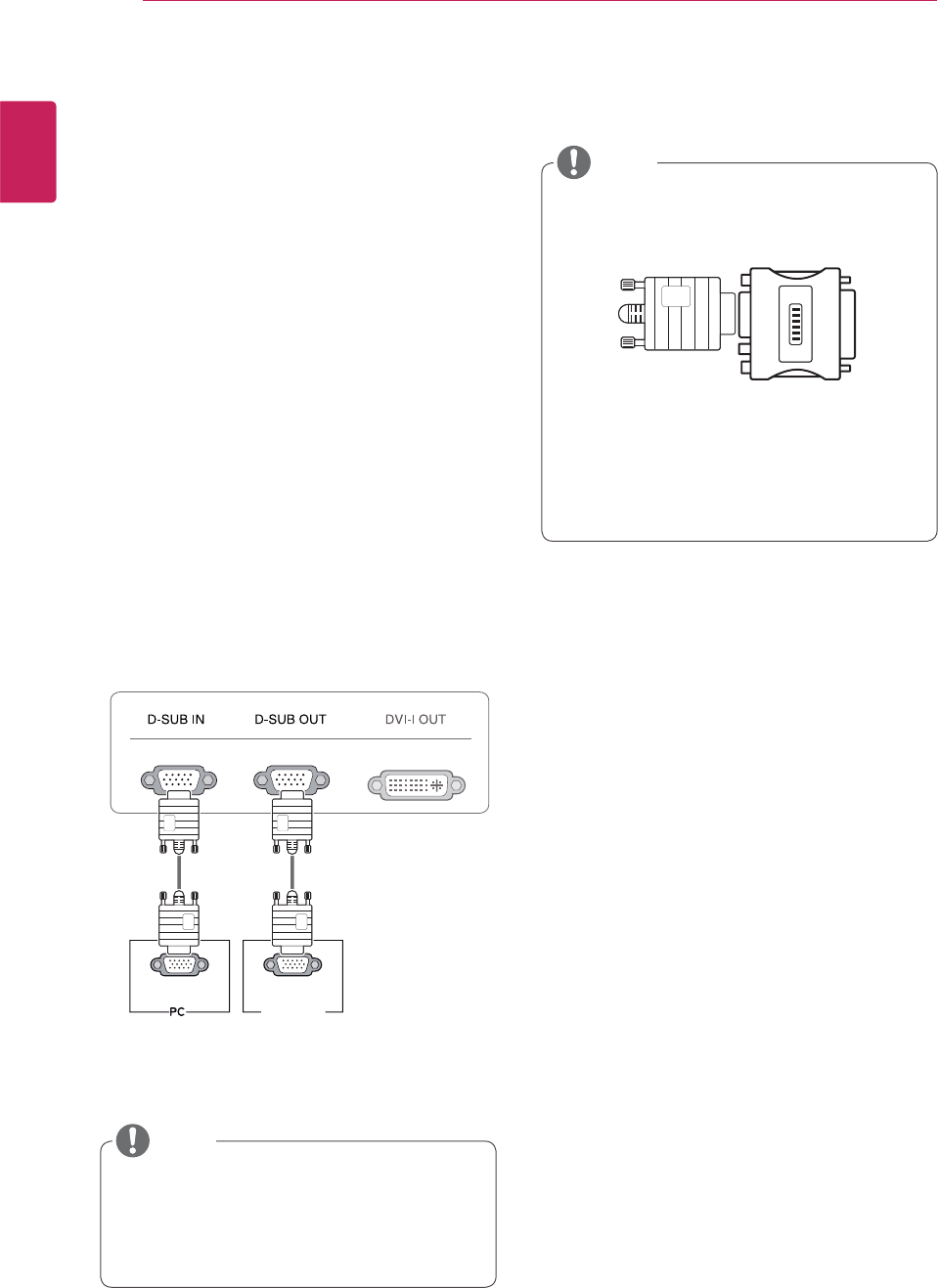
D-SUB connection
D-SUB IN transfers analog video signals from the
PC to the monitor.
D-SUB OUT can only replicate the image dis-
played on the monitor. (it does not support an
extended monitor.)
Connect the monitor to the PC using the provided
15-pin D-SUB signal cable as illustrated below.
y Macintosh Adaptor: Use the standard Ma-
cintosh adaptor. Other commercial adaptors
may not be compatible (due to the signaling
difference).
y When using a Macintosh D-SUB input cable
RGB OUT RGB IN
MONITOR
y When using this device simply as a regu-
lar monitor through the RGB IN port, set
"PCoIP" to OFF in MENU > OTHERS to
reduce energy consumption.
NOTE
NOTE
13
ENG
English
Using the Monitor
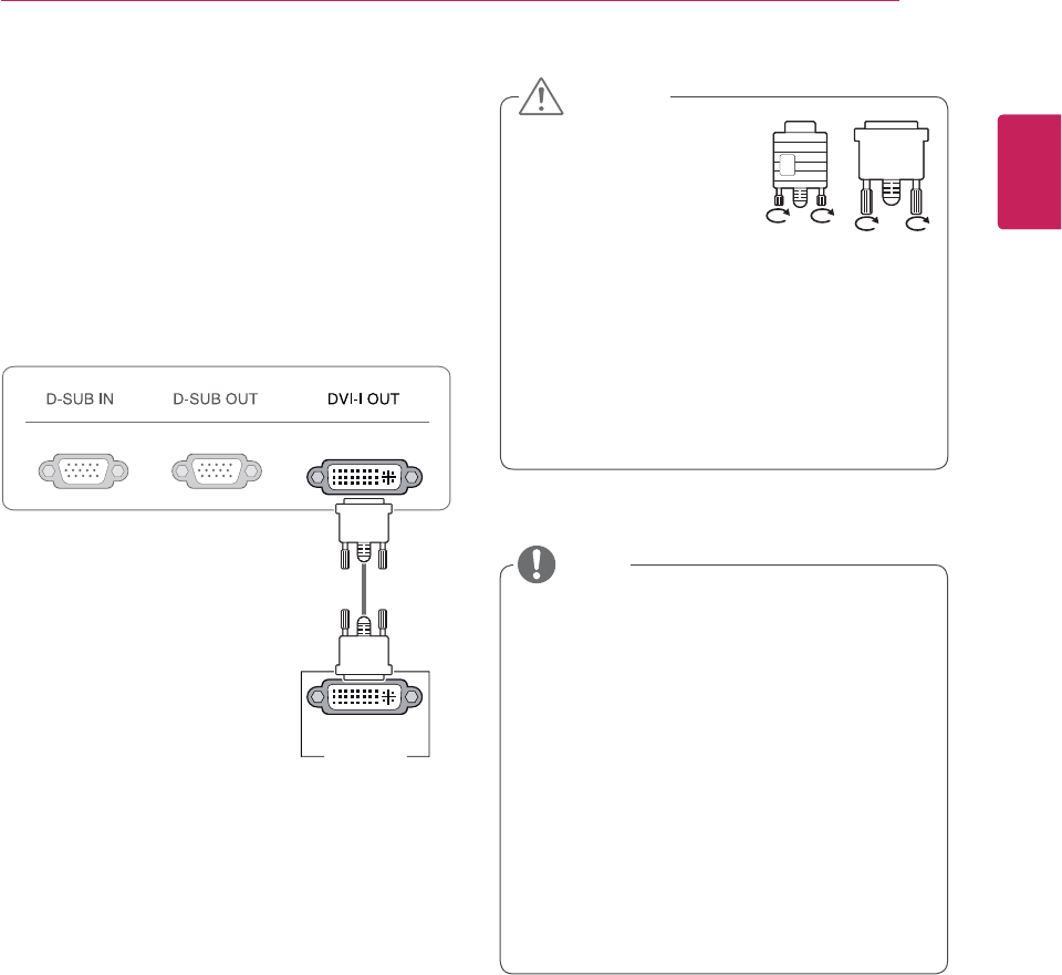
DVI connection - PCoIP
Transfers digital video signals to another monitor.
Connect the monitor using the DVI cable as illus-
trated below.
This connection is used to support an extended
monitor or replicate the image displayed on the
monitor.
y To connect the monitor to a computer, use
the appropriate signal cable (LAN and D-
SUB).
y A converter can be used to convert the DVI-I
input signal to D-SUB input signal.
y When connecting the power cord to the out-
let, use a grounded (3-hole) multi-socket or a
grounded wall outlet.
y The monitor may flicker when turned on in an
area of low temperature. This is normal.
ySometimes red, green or blue spots may ap-
pear on the screen. This is normal.
yConnect the input sig-
nal cable and turn in the
direction of the arrow. To
prevent disconnection
secure the cable tightly.
y Do not press on the screen for a prolonged
time. This may cause image distortion.
yDo not display a still image on the screen
for a prolonged time. This may cause image
retention. If possible, use the screen saver.
DVI-I(D) IN
MONITOR
CAUTION
NOTE
14
ENG
English
Using the Monitor
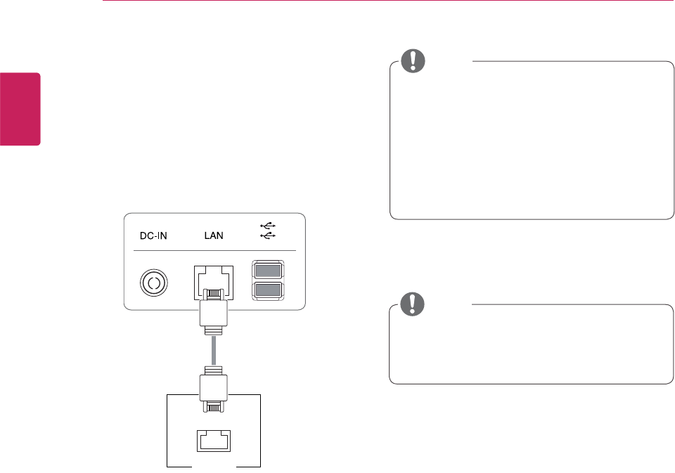
Connecting LAN/Peripherals
LAN connection - PCoIP
Transfers PCoIP signals to the monitor. Connect
the router or switch to the monitor using a LAN
cable as illustrated below.
y The LAN cable is sold separately.
y The following LAN cable type can be used:
Standard: IEEE 802.3 ETHERNET
y When connecting the Earphone Out or Line
Out through the LAN, use the volume icon on
the taskbar of your PC to adjust the volume.
y Connect the LAN cable and the peripheral
device prior to booting up the PC.
LAN
Hub/Router
NOTE
NOTE
15
ENG
English
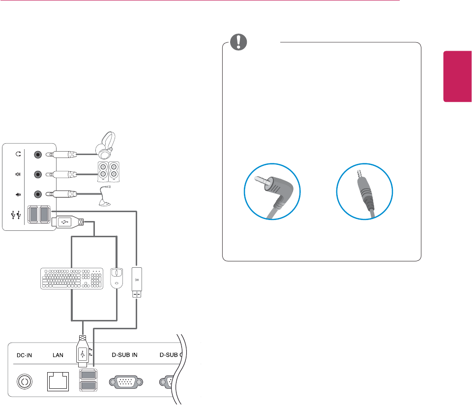
y Peripheral devices are sold separately.
y The USB ports on the left and bottom of the
monitor can be used to connect the key-
board, mouse, and other USB devices.
y For an angle plug earphone/microphone, it is
difficult connect it with a peripheral device, so
use a straight type.
Angle Type Straight Type
Peripheral device connection
Connect a peripheral device to the monitor us-
ing the USB, headphone, earphone, and speaker
ports. Connect the peripheral device to the monitor
as illustrated below.
Left
Bottom
NOTE
16
ENG
English
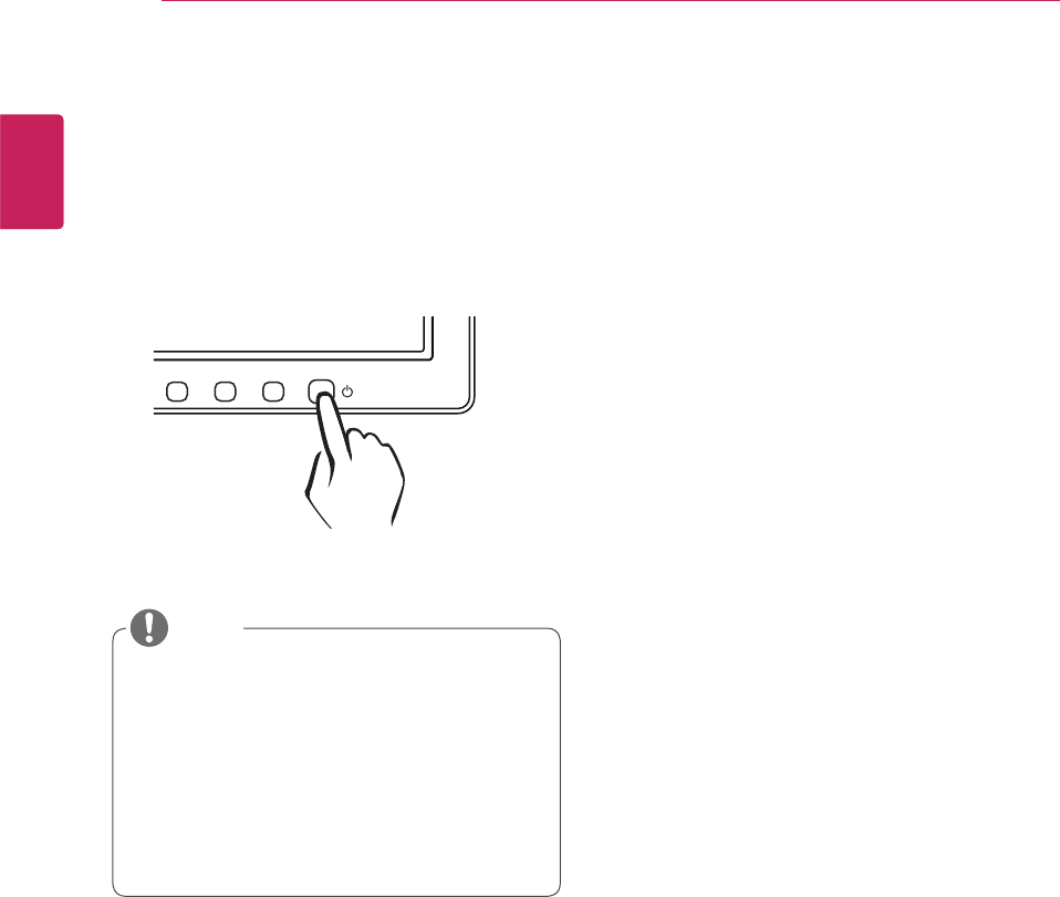
y What is "Self Image Adjustment"? This func-
tion runs when the monitor is connected for
the first time and performs automatic image
adjustment for each signal (only available for
analog [D-SUB input] signals) to provide an
optimal screen display.
Self Image Adjustment
Press the power button on the front to turn on
the monitor. When powered on, the "Self Image
Adjustment" function will run automatically (only
available for analog [D-SUB input] signals).
NOTE
17
ENG
English
MENU MODE AUTO INPUT EXIT
MONITOR SETUP
USER CONFIGURATION
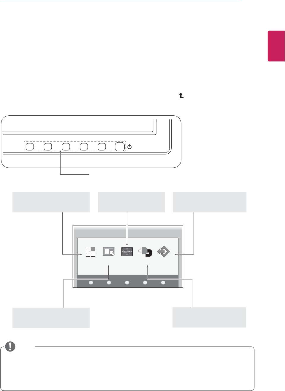
Activating the Main Menu
1 Press any button on the front of the monitor to display the MONITOR SETUP OSD menu.
2 Press to select the desired menu item.
3 To change the settings of the selected item press the buttons on the front of the monitor.
To return to the upper menu or set other menu items, use the up arrow ( ) button.
4 Select EXIT to leave the OSD menu.
MENU (See p.18)
Sets the screen options.
EXIT(See p.5)
Exits the OSD menu.
AUTO (See p.24)
Optimizes the resolution.
Different menu items are enabled depending on the type of input signal.
y D-SUB/PCoIP Input: MENU, MODE, AUTO, INPUT, EXIT
y The language of the monitor's OSD menu and that of the OSD menu illustrated in the CD-ROM
manual may be different.
Front Side Buttons
MODE (See p.22)
Sets the screen mode.
INPUT (See p.5)
Sets the external input.
NOTE
18
ENG
English
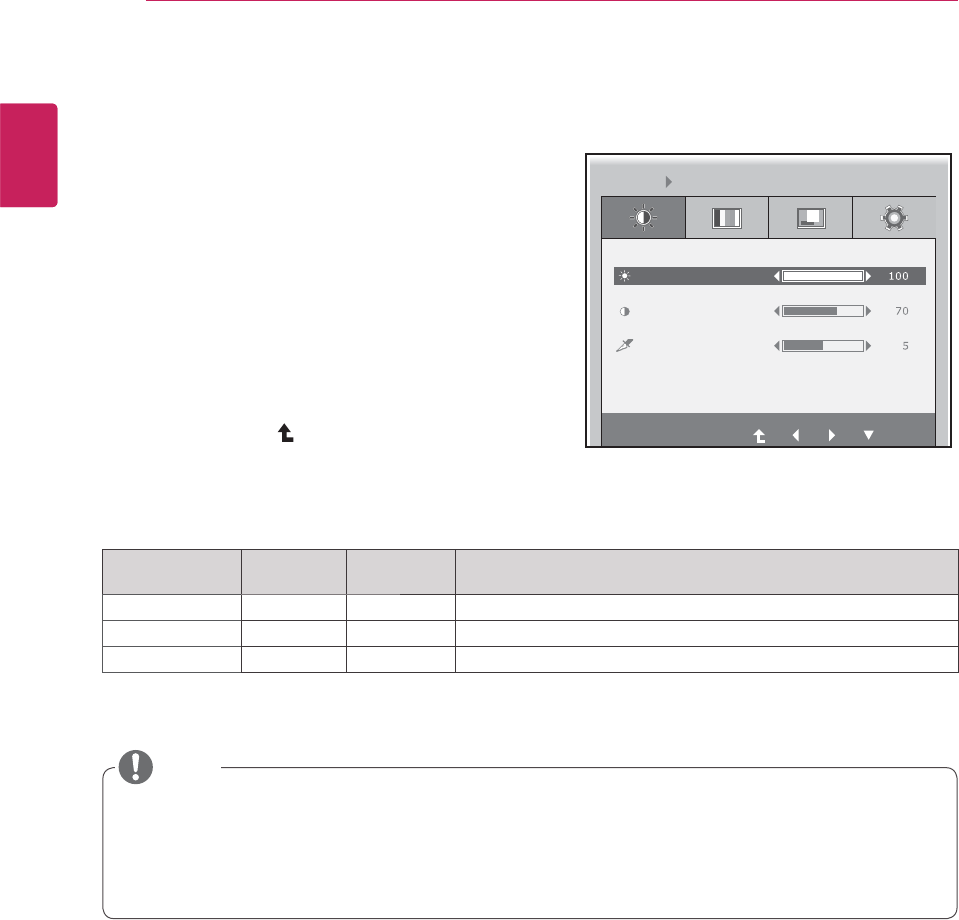
MENU Settings
Picture
1 Press any button on the front of the monitor to dis-
play the MONITOR SETUP OSD menu.
2 Press the MENU button to display the options in the
OSD menu.
3 Set the options by pressing the buttons on the front
of the monitor.
4 Select EXIT to leave the OSD menu.
To return to the upper menu or set other menu items,
use the up arrow ( ) button.
Each option is explained below.
Menu Analog
(D-SUB)
PCoIP Description
BRIGHTNESS
Sets the brightness of the screen.
CONTRAST
Sets the contrast of the screen.
SHARPNESS
Sets the sharpness of the screen.
y If the screen is not displayed properly after adjusting the settings, use the "FACTORY RESET"
option to revert back to the factory default settings. If necessary, enable the "WHITE BALANCE"
option again. This option is enabled only for analog (D-SUB) signals.
y Analog: D-SUB (analog signal) input. PCoIP: Internal signal through the LAN.
BRIGHTNESS
CONTRAST
MENU PICTURE
SHARPNESS
EXIT
NOTE
19
ENG
English
Menu Analog
(D-SUB)
PCoIP Description
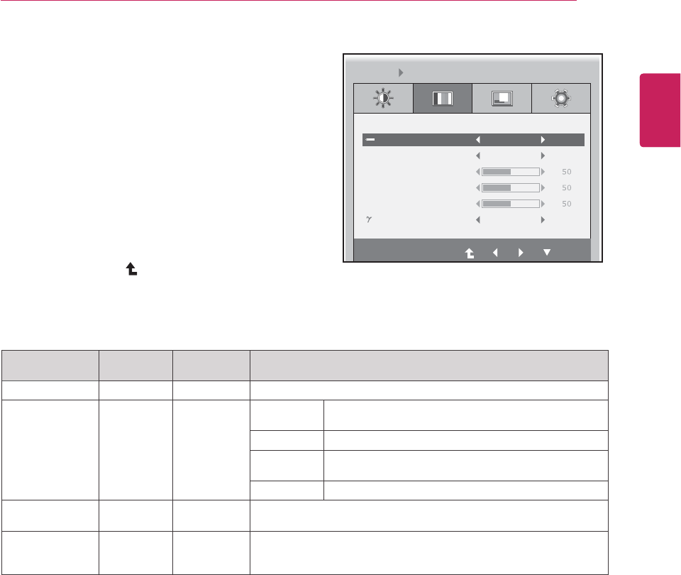
COLOR TEMP
Allows PRESET or USER to be selected.
PRESET
sRGB Sets the screen color according to the sRGB color
standard.
WARM Sets the screen color to a reddish tone.
STANDARD Sets the screen color between the reddish and bluish
tone.
COOL Sets the screen color to a bluish tone.
USER x
You can customize the picture color using Red, Green, and Blue
colors.
GAMMA
Sets the clarity of the screen.
The gamma value can be set to 0, 1 or 2, from darker to brighter
screen colors respectively.
y Analog: D-SUB (analog signal) input. PCoIP: Internal signal through the LAN.
Color
1 Press any button on the front of the monitor to dis-
play the MONITOR SETUP OSD menu.
2 Press the MENU button to display the options in the
OSD menu.
3 Set the options by pressing the buttons on the front
of the monitor.
4 Select EXIT to leave the OSD menu.
To return to the upper menu or set other menu items,
use the up arrow ( ) button.
Each option is explained below.
COLOR TEMP PRESET
PRESET
GAMMA GAMMA 1
RED
GREEN
BLUE
WARM
MENU COLOR
EXIT
20
ENG
English
Menu Analog
(D-SUB)
PCoIP Description
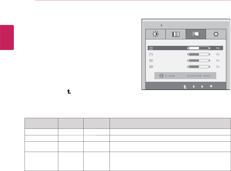
HORIZONTAL xMoves the display area left or right.
VERTICAL xMoves the display area up or down.
FREQUENCY xIf vertical lines are shown on the screen, adjust the frequency to mini-
mize the lines and adjust the screen's horizontal width.
PHASE
x
Adjusts the focus of the screen's image.
Use when frequencies are shown on the screen or when the text ap-
pears overlapped. For optimal results, use this option after adjusting
the "FREQUENCY" option.
y Analog: D-SUB (analog signal) input. PCoIP: Internal signal through the LAN.
Display
1 Press any button on the front of the monitor to dis-
play the MONITOR SETUP OSD menu.
2 Press the MENU button to display the options in the
OSD menu.
3 Set the options by pressing the buttons on the front
of the monitor.
4 Select EXIT to leave the OSD menu.
To return to the upper menu or set other menu items,
use the up arrow ( ) button.
Each option is explained below.
HORIZONTAL
EXIT
VERTICAL
FREQUENCY
PHASE
MENU DISPLAY
21
ENG
English
Menu Analog
(D-SUB)
PCoIP Description
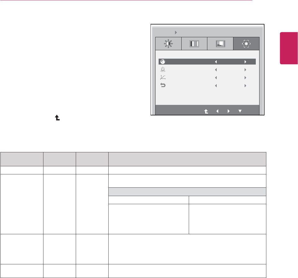
LANGUAGE
Sets the menu screen to the desired language.
PCoIP
x
Allows the PCoIP to be turned ON or OFF.
If the input is PCoIP
, the "PCoIP" option is disabled.
This option is enabled when analog signals are input via D-SUB.
If PCoIP is ON If PCoIP is OFF
- Use the INPUT button to switch
between PCoIP and D-SUB.
- If the D-SUB cable is removed,
the input will automatically be
switched to PCoIP.
- If the D-SUB cable is removed,
"No Signal" will be displayed.
- If INPUT is set to D-SUB, when
DC is switched from ON to OFF,
PCoIP will not be enabled.
WHITE BAL-
ANCE
x
If the video card output is different from the specified level, the color
may appear to have altered due to the video signal distortion. The
white balance adjusts the output signal level to correspond to that of
the standard signal, thus providing optimal display. Run this option
when the screen displays an image with both white and black.
FACTORY RE-
SET
Resets the screen to the factory default settings. Note that the lan-
guage option will not be reset.
y Analog: D-SUB (analog signal) input. PCoIP: Internal signal through the LAN.
Others
1 Press any button on the front of the monitor to dis-
play the MONITOR SETUP OSD menu.
2 Press the MENU button to display the options in the
OSD menu.
3 Set the options by pressing the buttons on the front
of the monitor.
4 Select EXIT to leave the OSD menu.
To return to the upper menu or set other menu items,
use the up arrow ( ) button.
Each option is explained below.
LANGUAGE
EXIT
English
Power Indicator ON
NO
NO
WHITE BALANCE
FACTORY RESET
MENU OTHERS
22
ENG
English
Menu Analog
(D-SUB)
PCoIP Description
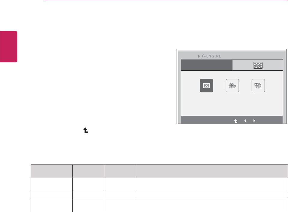
NORMAL
Select this option for everyday viewing.
* If F-ENGINE is not set to NORMAL, CONTRAST is disabled.
MOVIE
Select this option when watching videos or movies.
INTERNET
Select this option when working on a document (e.g. Microsoft Word)
for a prolonged period of time.
MODE Settings
F-ENGINE
1 Press any button on the front of the monitor to dis-
play the MONITOR SETUP OSD menu.
2 Press the MODE button to display the options in the
OSD menu.
3 Set the options by pressing the buttons on the front
of the monitor.
4 Select EXIT to leave the OSD menu.
To return to the upper menu or set other menu items,
use the up arrow ( ) button.
Each option is explained below.
y Analog: D-SUB (analog signal) input. PCoIP: Internal signal through the LAN.
EXIT
NORMAL MOVIE INTERNET
MODE
E
23
ENG
English
y Analog: D-SUB (analog signal) input. PCoIP: Internal signal through the LAN.
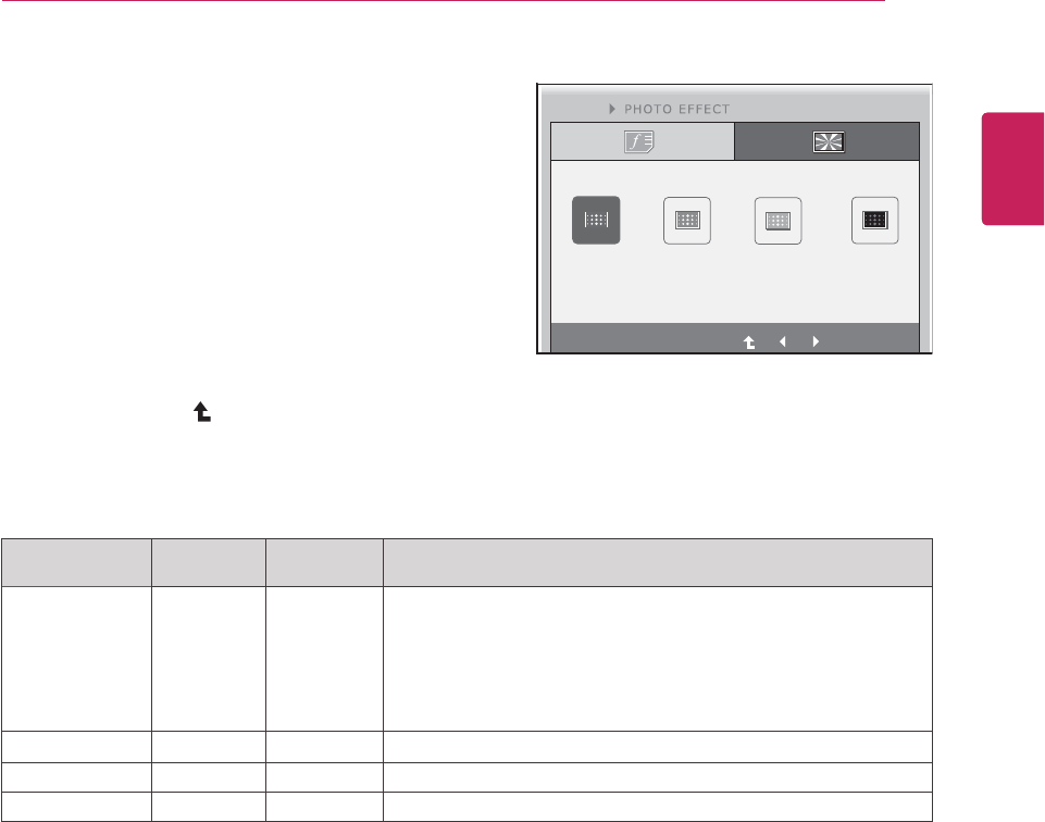
PHOTO EFFECT
1 Press any button on the front of the monitor to dis-
play the MONITOR SETUP OSD menu.
2 Press the MODE button to display the options in the
OSD menu.
3 Set the options by pressing the buttons on the front
of the monitor.
4 Select EXIT to leave the OSD menu.
To return to the upper menu or set other menu items,
use the up arrow ( ) button.
Each option is explained below.
Menu Analog
(D-SUB)
PCoIP Description
NORMAL
The PHOTO EFFECT option is disabled.
* If the PHOTO EFFECT option is not set to NORMAL, the CON-
TRAST is disabled and the screen is in grayscale.
If you choose to display the screen in color, PHOTO EFFECT will be
set to NORMAL and CONTRAST will be enabled.
PHOTO EFFECT and F-ENGINE cannot be enabled at the same
time.
GAUSSIAN
Displays the screen brighter and in a softer tone.
SEPIA
Displays the screen in sepia (brown) tone.
MONOCHROME
Displays the screen in grayscale (black and white).
EXIT
English
NORMAL GAUSSIAN SEPIA MONOCHROME
MODE
E
XIT
24
ENG
English
AUTO Settings
1 Press any button on the front of the monitor to dis-
play the MONITOR SETUP OSD menu.
2 Press the AUTO button to automatically adjust the
screen.
3 Select EXIT to leave the OSD menu.
To return to the upper menu or set other menu items,
use the up arrow ( ) button.
Pressing the AUTO button allows the monitor to automatically optimize the screen to the current display
mode.
If you are not satisfied with the optimized screen, you can manually adjust the position of the display area,
frequency, phase and sharpness in the OSD menu.
(Only available for D-SUB [analog] signals. Note that the sharpness setting is only available for digital sig-
nals.)
PROCESSING AUTO IMAGE ADJUSTMENT
FOR OPTIMAL DISPLAY
CHANGE RESOLUTION TO 1280 x 1024
y What is "Auto Image Adjustment"? The Auto Image Adjustment option allows you to improve the
picture quality if the screen is dimmed, if the text appears blurred or spread, if the screen flickers or
if the display area is not centered after adjusting the resolution. (Only available for D-SUB [analog]
signals.)
NOTE
25
ENG
English
Troubleshooting
TROUBLESHOOTING
Nothing is displayed on the screen
Is the monitor's power cord plugged in?
yCheck if the power cord is correctly plugged in to the outlet.
Is the power indicator on?
yCheck the power indicator.
Is the power indicator displaying as
white?
yAdjust the brightness and the contrast.
Is the power indicator blinking?
yIf the monitor is in power saving mode, move the mouse or press any
key on the keyboard to switch the display on.
yCheck if the computer is turned on.
Is the "OUT OF RANGE" message
displayed?
yThis occurs when signals transferred from the PC (video card) are out
of the horizontal or vertical frequency range of the monitor. Please see
the "Product Specification" section of this manual to set the appropri-
ate frequency.
Is the "CHECK SIGNAL CABLE"
message is displayed?
yThis is displayed when the signal cable between the PC and the moni-
tor is missing or disconnected. Check the cable and reconnect.
The "OSD LOCKED" message is displayed.
Is the "OSD LOCKED" message
displayed when the MENU button is
pressed?
yThe OSD lock feature is enabled to prevent undesired modification
of the OSD settings. Press and hold the MENU button for a couple of
seconds to unlock the OSD. (The "OSD UNLOCKED" message will be
displayed.)
The screen retains an image.
Does image sticking occur even
when the monitor is turned off?
yDisplaying a still image for a prolonged time may cause damage to the
screen, resulting in the retention of the image.
yUse a screen saver to protect the screen when using the monitor for a
prolonged period of time.
y Vertical Frequency: In order to display an image, the screen must be refreshed dozens of times per
second like a fluorescent lamp. The number of times the screen is refreshed per second is called
vertical frequency or refresh rate and is represented by Hz.
yHorizontal Frequency: The time it takes to display one horizontal line is called the horizontal cycle.
The number of horizontal lines displayed in one second
can be calculated by dividing one by the horizontal cycle. This is called horizontal frequency and is
represented by kHz.
NOTE
26
ENG
English
Troubleshooting
The image is displayed abnormally.
Does the display area appear un-
centered?
Pressing the AUTO button will automatically optimize the screen to the current
display mode.
If you are not satisfied with the optimized screen, you can manually adjust the
POSITION option in the OSD menu.
Does the screen exhibit vertical
lines?
Pressing the AUTO button will automatically optimize the screen to the current
display mode.
If you are not satisfied with the optimized screen, you can manually adjust the
FREQUENCY option in the OSD menu.
Does the screen display horizontal
frequencies, or does the text appear
blurred?
Pressing the AUTO button will automatically optimize the screen to the current
display mode.
If you are not satisfied with the optimized screen, you can manually adjust the
PHASE option in the OSD menu.
y Check if the video card's resolution or frequency is within the range allowed by the monitor and set to
the recommended (optimal) resolution in Control Panel > Display > Settings.
y Failing to set the video card to the recommended (optimal) resolution may result in blurred text, a
dimmed screen, a truncated display area or misalignment of the display.
yThe configuration procedure may differ depending on your computer and/or operating system. Also,
some video cards may not support certain resolutions. If this is the case, contact the computer or
video card manufacturer for assistance.
y The AUTO option is only available for D-SUB (analog) signals.
The display color is abnormal.
Does the display color appear dis-
colored (16 color)?
ySet the color to 24 bit (true color) or higher. In Windows, go to Control
Panel > Display > Settings > Color Quality.
Does the display color appear un-
stable or in monochrome?
yCheck if the signal cable is connected properly. Re-connect the cable
or re-insert the PC's video card.
Are there spots on the screen?
yWhen using the monitor, pixilated spots (red, green, blue, white or
black) may appear on the screen. This is normal for the LCD screen.
It is not an error nor is it related to the monitor's performance.
NOTE
27
ENG
English
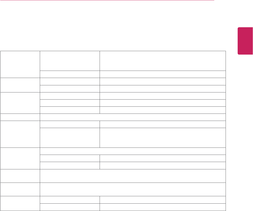
PRODUCT SPECIFICATION
N1910LZ
LCD Screen Type 481 mm (19 inch) TFT (Thin Film Transistor)
LCD (Liquid Crystal Display) Screen
Diagonal length of the screen: 481 mm
Pixel Pitch 0.2835 x 0.2835 mm
Resolution Maximum Resolution 1280 x 1024 @ 60 Hz
Recommended Resolution 1280 x 1024 @ 60 Hz
Video Signal Horizontal Frequency 30 kHz - 66 kHz
Vertical Frequency 57 Hz - 63 Hz
Synchronization Separate Sync/PCoIP
Input Connector 15-pin D-SUB (Analog)
Power Rated Voltage AC 100-240V 50/60Hz 1.2A
Power Consumption On Mode: 43 W (Typical)
Dimension/
Weight
Monitor Size (Width x Height x Depth)
With Stand 408.9 mm x 480.8 mm x 139 mm
Without Stand 408.9 mm x 338.1 mm x 56.9 mm
Weight (Without
Packaging)
3.5 kg
Stand Angle
Adjustment
Forwards/Backwards: -5° to 15° (Monitor)
Environment
Condition
Operating Condition Temperature: 10°C to 35°C; Humidity: 10% to 80%
Storing Condition Temperature: -20°C to 60°C; Humidity: 5% to 90%
The specifications are subject to change without notice.
28
ENG
English
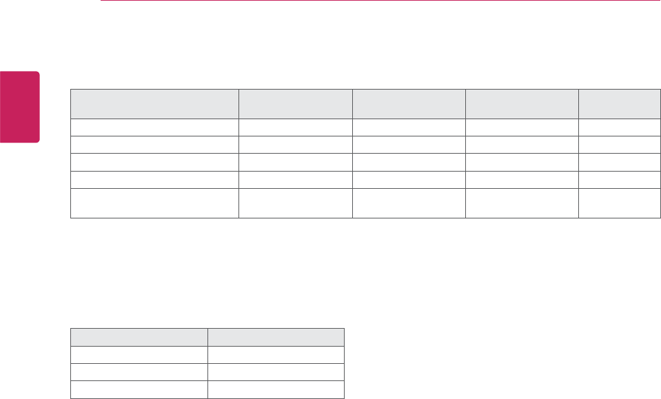
Preset Mode
Preset Mode Horizontal Frequen-
cy (kHz)
Vertical Frequency
(Hz) Polarity (H/V) Remark
720 x 400 31.468 70 -/+
640 x 480 31.469 60 -/-
800 x 600 37.879 60 +/+
1024 x 768 48.363 60 -/-
1280 x 1024 63.981 60 +/+ Recommended
Mode
Power Indicator
Mode LED Color
On Mode White
Power Saving Flashing White
Off Mode Off

29
ENG
English
Proper Posture
PROPER POSTURE
Proper posture for using the monitor
Adjust the angle so that the screen is slightly lower than your eyes.
y Using the monitor for a prolonged period of time can cause eye fatigue. Take a 10-minute break every
hour.
yThe stand is designed to best support the monitor when the optimal conditions are selected.
Adjust the angle of the monitor from -5° to 15° to obtain the best view of the screen.
You should be
looking
slightly down at
the screen.
Place your hands gently
on the keyboard,
keeping your arms bent at
the elbows
and extended horizontally
in front of you.
Adjust the angle
from -5° to 15°
so that there is no re-
flection
or glare from the
screen.
30
ENG
English
Using PCoIP Solution
USING PCOIP SOLUTION
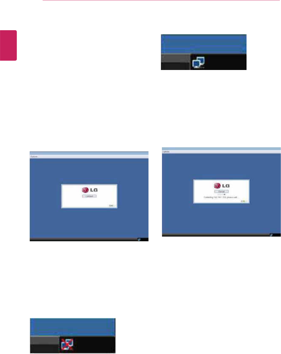
Selecting the Connect button initiates a PCoIP or
RDP session depending on the session settings.
While the PCoIP connection is pending, the OSD
local GUI will display a "Connection Pending"
message. When the connection is established, the
OSD local GUI will disappear and be replaced by
the session image.
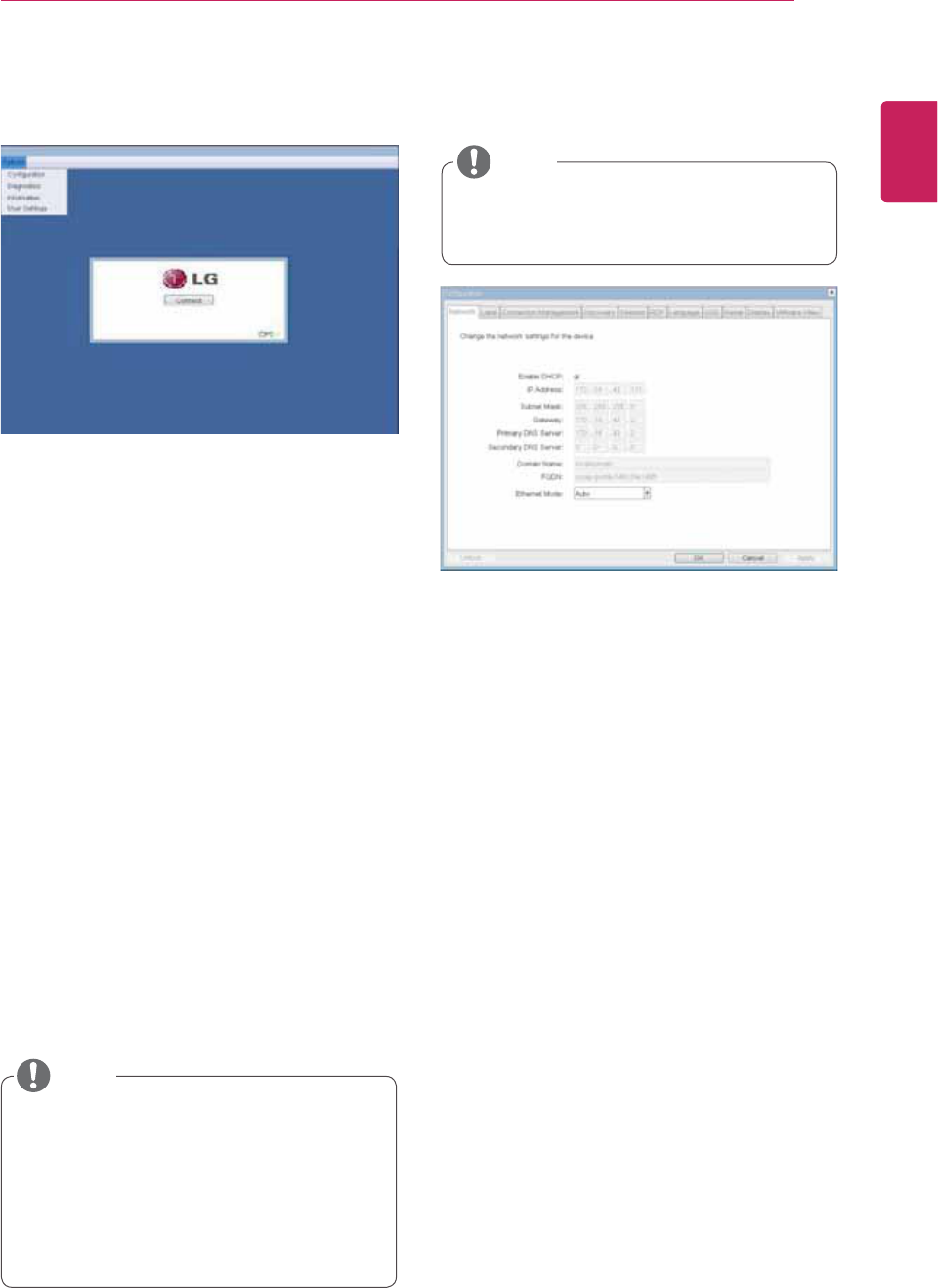
OSD Options Menu
Selecting the Options menu will produce a list of
selections. The OSD Options menu contains:
yConfiguration
yDiagnostics
yInformation
yUser Settings
A red "X" over the network icon indicates that
either the network is not properly connected or that
the connection is still being initialized (i.e. during
portal boot up). Figure 2-2 shows the red "X" over
the network icon indicating that the network is not
ready.
Figure 2-3 shows the network icon when ready.
Figure 2-1. OSD Connect Screen
Figure 2-4. OSD Connect Screen (Connecting)
Figure 2-2. Network Not Ready (Detail)
Figure 2-3. Network Ready (Detail)
Connect Screen
The Connect screen is shown during start-up,
except when the portal has been configured for a
managed start-up or auto-reconnect. The logo dis-
played above the Connect button can be changed
by uploading a replacement image via the admin
interface. The network icon on the bottom right of
the Connect screen shows the status of the net-
work connection. You must wait until the network
icon is displayed as shown in Figure 2-3.
Selecting one of the options will produce a settings
window.
31
ENG
English
Using PCoIP Solution
Figure 2-5. OSD Options Menu
Configuration Window
In the Configuration window, the administrator can
access the window tabs that contain the settings to
configure and manage the portal environment.
The Configuration window has the following tabs:
yNetwork
yLabel
yConnection Management
yDiscovery
ySession
yRDP
yLanguage
yOSD
yReset
yDisplay
yVMware View
Figure 2-6. Network Configuration
Each tab contains OK, Cancel and Apply buttons
to allow the administrator to apply or cancel the
modified settings.
yEnable DHCP
If the Enable DHCP option is selected, a device will
be connected to the DHCP server. that allocates
the IP address, subnet mask, gateway IP address,
and DNS server. If this option is disabled, the
above parameters must be configured manually.
yIP Address
The IP Address field contains the IP address of the
device. If DHCP is disabled, this field is required.
If DHCP is enabled, this field cannot be edited.
This field must contain the correct IP address. If an
incorrect IP address is provided, an OSD message
is displayed prompting the administrator to provide
the correct the IP address.
ySubnet Mask
The Subnet Mask field contains the subnet mask
of the device. If DHCP is disabled, this field is
required. If DHCP is enabled, this field cannot be
edited. This field must have the correct subnet
mask. If an incorrect subnet mask is provided, an
OSD message is displayed prompting the adminis-
trator to provide the correct the subnet mask.
Network Tab
The Network tab allows the administrator to config-
ure the portal network parameters.
y Some PCoIP devices have their password
protection disabled and can be logged into
the management web page or access the
OSD parameters without a password. The
login page and the OSD's password protec-
tion can be enabled in the PCoIP manage-
ment console.
y The network parameters can also be con-
figured using the Webpage Administration
Interface.
NOTE
Selecting one of the options will produce a settings
window.
NOTE
32
ENG
English
Using PCoIP Solution
Figure 2-7. Label Configuration
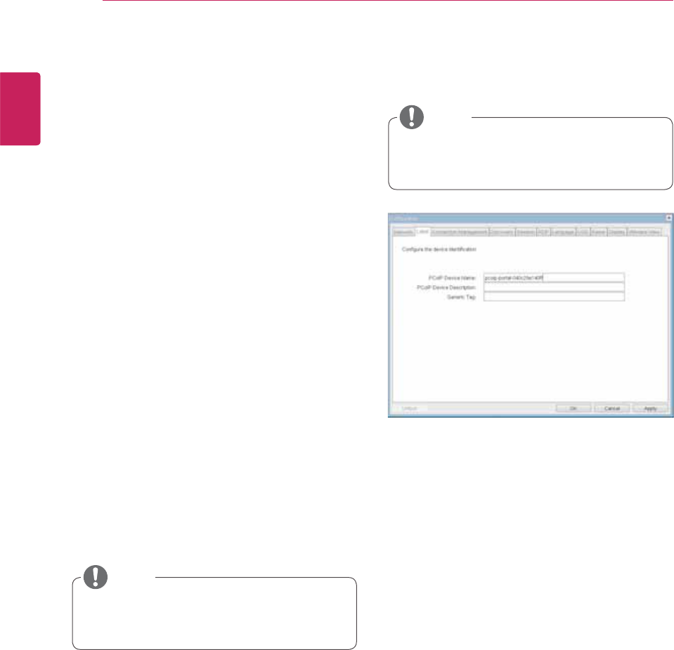
Label Tab
The Label tab allows the administrator or host to
add customized information to the portal.
y The portal label parameters can also be con-
figured using the Webpage Administration
Interface.
y In order to utilize the FQDN feature, a DNS
server, configured properly with DHCP option
81, must be used.
yGateway
The Gateway field contains the gateway IP ad-
dress of the device. If DHCP is disabled, this field
is required. If DHCP is enabled, this field cannot be
edited.
yPrimary DNS Server
The Primary DNS Server field contains the primary
DNS IP address of the device. This field is option-
al. If DHCP is enabled, this field cannot be edited.
ySecondary DNS Server
The Secondary DNS Server field contains the sec-
ondary DNS IP address of the device. This field is
optional. If the DHCP is enabled, this field cannot
be edited.
yDomain Name
The Domain Name field contains the domain name
used, e.g. "domain local". This field is optional. It speci-
fies on which domain the host or portal operates.
yFQDN
The FQDN field represents the Fully Qualified Do-
main Name of the host or portal. The default value is
PCoIP-host-MAC or PCoIP-portal-MAC, where MAC
is the MAC address of the host or portal. If there is
a domain name, it will be added to the FQDN in the
format of PCoIP-host-MAC.domain.local
yPCoIP Device Name
In the PCoIP Device Name field, the administrator
can specify a logical name to the host or portal.
The default value is PCoIP-host-MAC or PCoIP-
portal-MAC, where MAC is the MAC address of the
host or portal.
yPCoIP Device Description
In the PCoIP Device Description field, the administra-
tor can add specific information, such as the endpoint
location, or add a description to the host or portal.
This field cannot be used in the PCoIP firmware and
accessibility is strictly limited to the administrator.
yGeneric Tag
In the Generic Tag field, the administrator can add a
generic tag to the host or portal.
This field cannot be used in the PCoIP firmware and
accessibility is strictly limited to the administrator.
yEthernet Mode
The Ethernet Mode field specifies the portal's Eth-
ernet mode.
The available options are as follows.
yAuto
y100 Mbps Full-Duplex
y10 Mbps Full-Duplex
If another network device is configured to oper-
ate under 10 Mbps Full-Duplex or 100Mbps Full-
Duplex, the administrator should always set the
Ethernet Mode field to Auto and only use 10 Mbps
Full-Duplex or 100 Mbps Full-Duplex.
NOTE
NOTE
33
ENG
English
Using PCoIP Solution
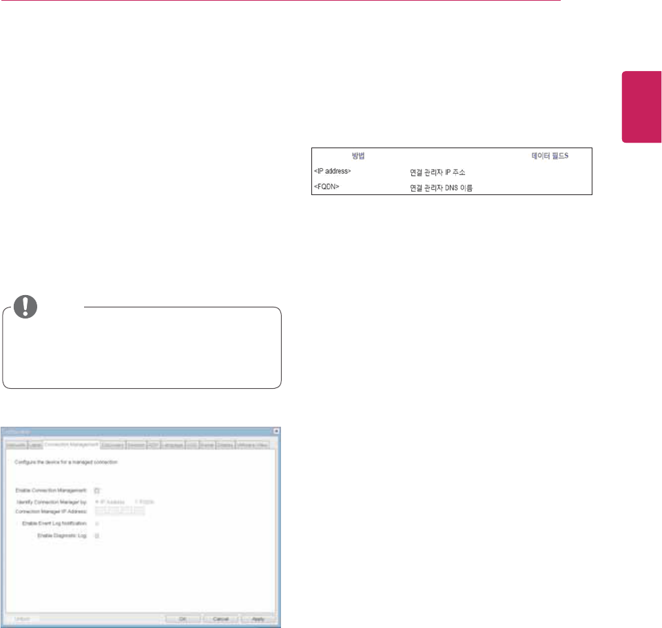
Figure 2-8. Connection Management Configuration
Table 2-1 Connection Manager Method
Connection Management Tab
The Connection Management tab allows the
user to enable or disable the connection man-
agement and specify the connection manager's
IP address.
In a managed connection, an external Connection
Management Server can communicate with a device
to remotely control and configure the device. The
connection manager can also search for an ap-
propriate peer to connect to the device. Connection
Management significantly reduces the tasks of the
administrator in a large and complicated system.
Table 2-1 shows the configuration parameters that
can be used with one of the two methods. If an
incorrect IP address or DNS name is provided, an
OSD message is displayed prompting the adminis-
trator to correct the error.
y The Connection Management parameters
can also be configured using the Webpage
Administration Interface.
yEnable Connection Management
If the Enable Connection Management option is
enabled, the device can be controlled and config-
ured from an external connection manager.
yIdentify Connection Manager By
The Identify Connection Manager By selector al-
lows the administrator to decide whether to iden-
tify the connection manager by IP Address or by
FQDN. If Connection Management is disabled,
this field is not required and can therefore not be
edited.
yEnable Event Log Notification
The Enable Event Log Notification field controls
whether the PCoIP host and the portal devices will
send their event log to the connection manage-
ment server.
yEnable Diagnostic Log
The Enable Diagnostic Log field specifies whether
to log the connection management specific debug
message to the PCoIP host and to the portal de-
vices' event logs.
NOTE
34
ENG
English
Using PCoIP Solution
Table 2-2. Peer ID Method
yEnable Discovery
If the Enable Discovery option is selected, a device
will use SLP Discovery to dynamically locate the
peer device without requiring any information about
the location of the device in the network. This
means that the configuration and maintenance
work in a complicated system can be significantly
reduced.
As SLP Discovery requires a multicast-enabled
router, the recommended search structure is DNS-
SRV Discovery.
yEnable Host Discovery
The Enable Host Discovery option allows the user
to find the host not listed in the PCoIP session
from the portal. When this option is enabled, up
to 10 available hosts can be listed, in the order
of their detection from the portal. Use the Enable
Host Discovery option when there are a relatively
small number of hosts.
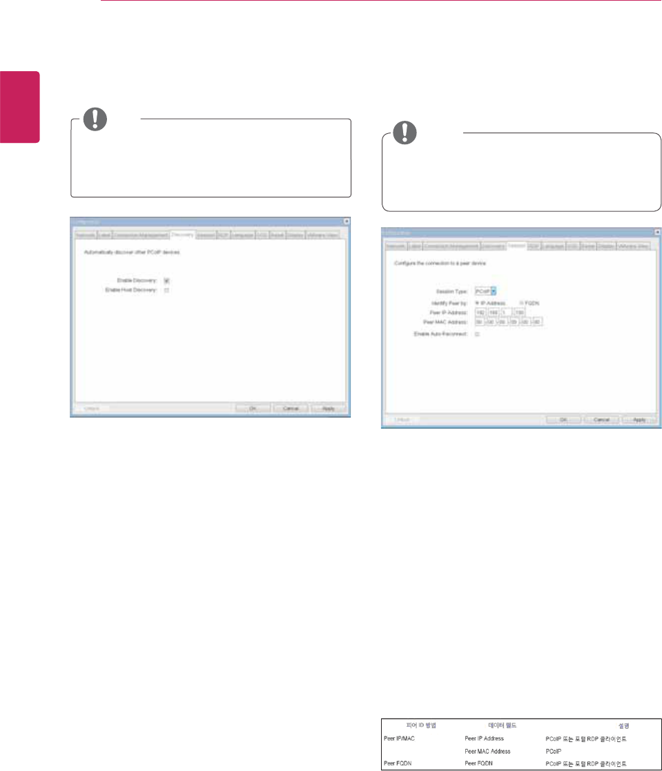
ySession Type
In Session Type, the administrator can configure a
portal for the PCoIP session or the RDP session.
yIdentify Peer By
The Identify Peer By selector allows the adminis-
trator to decide whether to identify the peer device
by IP, by MAC address or by FQDN.
Table 2-2 shows the peer ID parameters that can
be used with one of the two methods. If an incor-
rect IP address or DNS name is provided, an OSD
message is displayed prompting the administrator
to correct the error.
yEnable Auto-Reconnect
The Enable Auto-Reconnect option allows the por-
tal to automatically reconnect to the last connected
host when the session is closed.
Figure 2-9. Discovery Configuration Figure 2-10. Session Configuration
Discovery Tab
The Discovery tab allows the administrator to eas-
ily find a portal in the PCoIP system.
Session Tab
The Session tab allows the administrator to set the
method to connect the device to a peer device.
y The Discovery parameters can also be con-
figured using the Webpage Administration
Interface.
y The Session parameters can also be con-
figured using the Webpage Administration
Interface.
NOTE
NOTE
35
ENG
English
Using PCoIP Solution
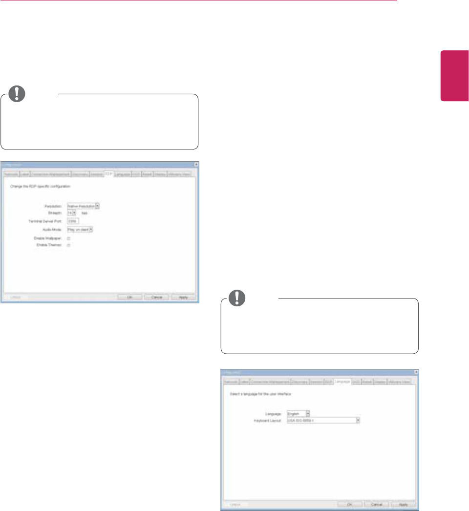
yResolution
The Resolution field is used to set the RDP screen
resolution. The available values are as follows.
y/BUJWF3FTPMVUJPO
yY
yY
yY
yY
yY
yY
yY
yY
yY
yBit Depth
The Bit Depth field is used to set the color bit depth
for the RDP session. The available values are as
follows.
yCQQCJUTQFSQJYFM
yCQQ
yCQQ
yTerminal Server Port
The Terminal Server Port field is used to set the
port number to connect the RDP client.
yLanguage
The Language field is used to set the display
language of the OSD and the user level event log
messages.
yKeyboard Layout
The Keyboard Layout field allows the administrator
to modify the keyboard layout.
Figure 2-11. RDP Configuration
Figure 2-12. Language Configuration
RDP Tab
The RDP tab allows the administrator to configure
the remote desktop protocol (RDP) specific set-
tings.
Language Tab
The Language tab allows the administrator to set
the OSD language.
y The RDP Label parameters can also be con-
figured using the Webpage Administration
Interface.
y The Language parameters can also be con-
figured using the Webpage Administration
Interface.
yAudio Mode
The Audio Mode field is used to set the audio play-
back location of the RDP session. The available
options are as follows.
y/POF
y1MBZPODMJFOU
y1MBZPOIPTU
yEnable Wallpaper
The Enable Wallpaper field is used to allow the
user to use the wallpaper in the RDP session.
yEnable Themes
The Enable Themes field is used to enable the user
to use the wallpaper theme in the RDP session.
NOTE
NOTE
36
ENG
English
Using PCoIP Solution
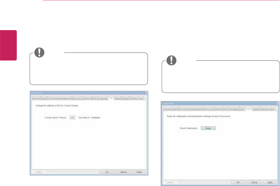
yScreen-Saver Timeout
The Screen-Saver Timeout field allows the ad-
ministrator to set a time limit for the screen saver.
The time limit is defined in seconds. The maximum
time is 9999 seconds. If it is set to 0 seconds, the
screen saver will be turned off.
yReset Parameters
Pressing the Reset Parameters button will reset all
settings and options to the factory default settings.
When this button is pressed, an OSD message is
displayed. This is to prompt the administrator and
prevent accidental reset.
Figure 2-13. OSD Configuration
Figure 2-14 Reset
OSD Tab
The OSD tab allows the administrator to modify the
On Screen Display (OSD) parameters.
Reset Tab
The Reset tab allows the administrator to reset all
configurable parameters stored in Flash.
y The OSD parameters can also be configured
using the Webpage Administration Interface. y The Reset function can also be accessed
through the Webpage Administration Inter-
face.
NOTE
NOTE
37
ENG
English
Using PCoIP Solution
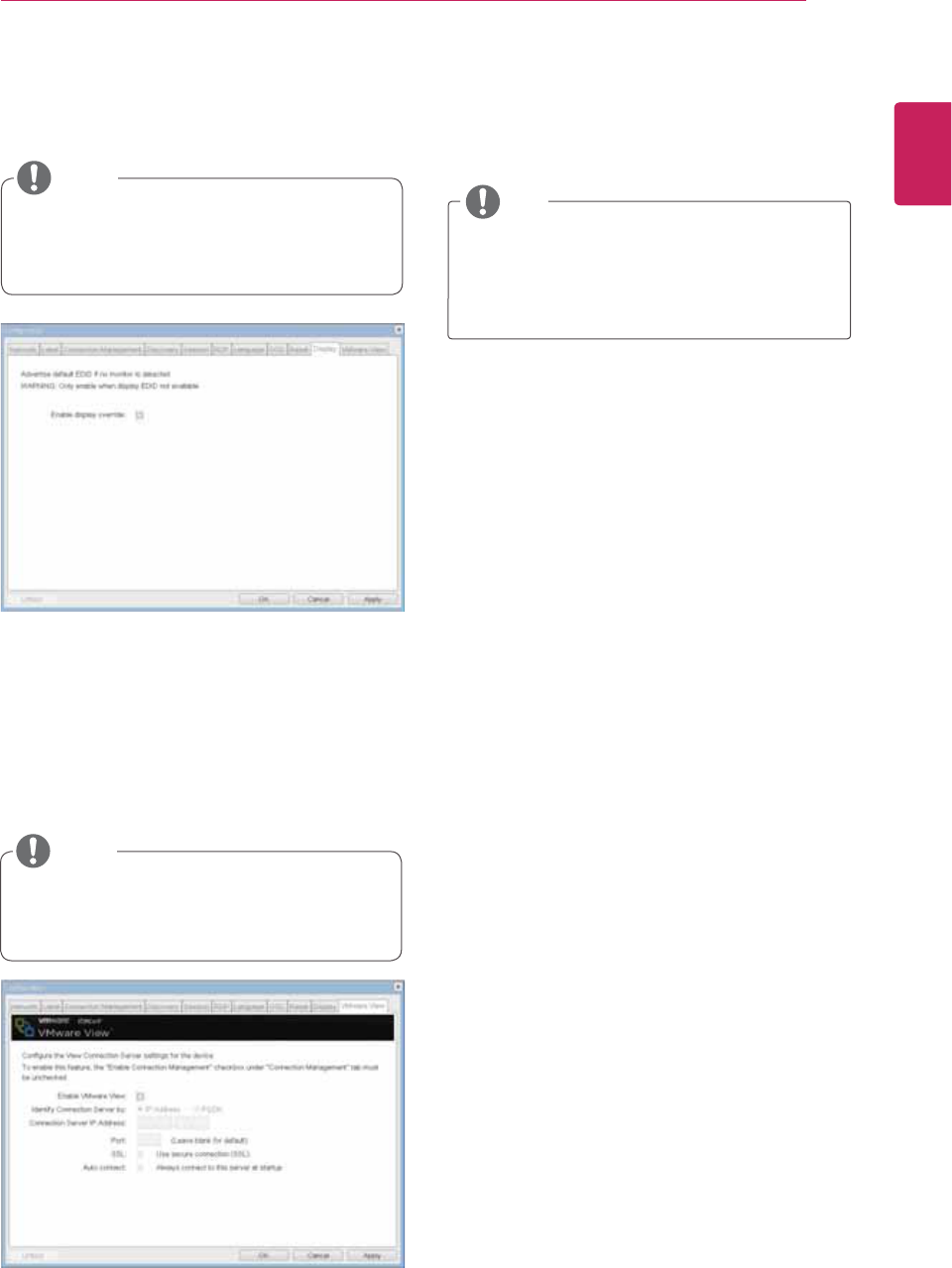
yEnable VMware View
The Enable VMware View option allows the user to
configure the portal to use the VMware View Con-
nection Server.
yIdentify Connection Server by
The Identify Connection Server by selector allows
the administrator to decide whether to identify the
connection manager by IP address or by FQDN. If
VMware View is disabled, this field is not required
cannot be edited.
yPort
The Port parameter allows the administrator to
specify the port to communicate with the VMware
View Connection Server.
ySSL
The SSL parameter allows the administrator to
specify the SSL to communicate with the VMware
View Connection Server.
yAuto Connect
The Auto Connect parameter allows the adminis-
trator to ensure that the device always automati-
cally connects to the VMware View Connection
Server when starting the portal.
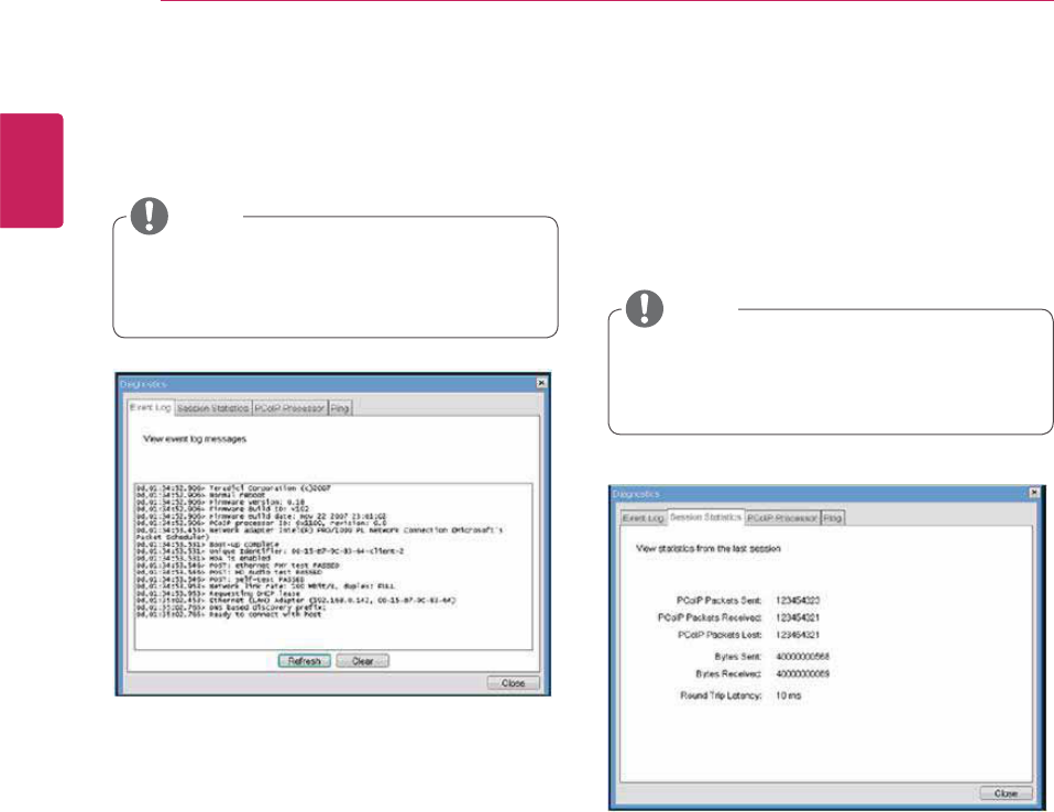
yEvent Log
ySession Statistics
yPCoIP Processor
yPing
Each tab has the Close button to close the window.
Figure 2-15. Display Configuration
Figure 2-16. VMware View Configuration
Display Tab
The Display tab allows the user to configure the
EDID function of the monitor.
Diagnostics Window
In the Diagnostics window, the administrator can
access the window tab to diagnose the portal. The
Diagnostics window has the following tabs:
VMware View Tab
The VMware View tab allows the user to select the
device to use the VMware View Connection Server.
y The Enable display override function can be
used when the EDID function of the monitor
is not running.
y The VMware View parameters can also be
configured using the Webpage Administra-
tion Interface.
y To enable the VMware View function, the
Enable Connection Management check box
in the Enable Connection Management Tab
must be deselected.
NOTE
NOTE
NOTE
38
ENG
English
Using PCoIP Solution
yView Event Log Message
The View Event Log Message field displays the log
messages accompanied by the timestamp informa-
tion. The following two buttons are available:
yRefresh
The Refresh button refreshes the displayed event
log messages.
yClear
The Clear button clears all event log messages.
yPCoIP Packets Statistics
yPCoIP Packets Sent
The PCoIP Packets Sent field shows the total
number of PCoIP packets sent from the portal
to the host in the last active session.
yPCoIP Packets Received
The PCoIP Packets Received field shows the
total number of PCoIP packets received from
the host to the portal in the last active session.
yPCoIP Packets Lost
The PCoIP Packets Lost field shows the total
number of PCoIP packets lost in the last ac-
tive session.
Figure 2-17. Event Log Configuration
Figure 2-18. Session Statistics Configuration
Event Log Tab
The Event Log tab allows the administrator to view
and delete the event log messages from the portal.
Session Statistics Tab
The Session Statistics tab allows the administrator
to view the PCoIP specific statistics of the last ac-
tive PCoIP session from the portal.
The session statistics (regardless of the quantity)
can also be viewed using the Webpage Administra-
tion Interface.
y The event log (regardless of the quantity)
can also be reset using the Webpage Admin-
istration Interface.
y The event log (regardless of the quantity)
can also be reset using the Webpage Admin-
istration Interface.
NOTE
NOTE
39
ENG
English
Using PCoIP Solution
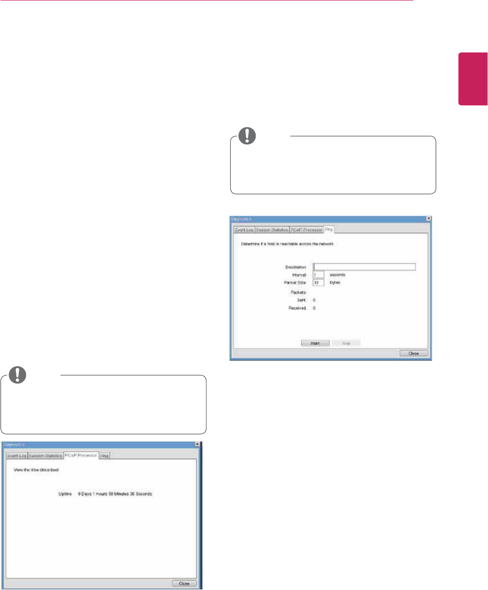
yPing Settings
yDestination
The IP address or FQDN to perform the ping
test.
yInterval
The interval between the ping packets.
yPacket Size
The size of the ping packet.
yPackets
ySent
The number of ping packets sent.
yReceived
The number of ping packets received.
Figure 2-19. PCoIP Processor Configuration
Figure 2-20. Ping Configuration
PCoIP Processor Tab
The PCoIP Processor tab allows the administrator
to view the portal PCoIP processor's uptime since
its last booting.
Ping Tab
The Ping tab allows the administrator to perform a
ping test to the device and check if it can reach the
overall IP network. This is useful to check whether
the device can reach the host.
y The PCoIP Processor Uptime can also be
viewed using the Webpage Administration
Interface.
y The Ping tab has no corresponding menu in
to the Webpage Administration Interface of
Section 1.
NOTE
yBytes Statistics
yBytes Sent
The Bytes Sent field shows the total number
of bytes sent in the last active session.
yBytes Received
The Bytes Received field shows the total
number of bytes received in the last active
session.
yRound Trip Latency
The Round Trip Latency field shows the total
round-trip PCoIP system (e.g. from the portal to
the host, then back to the portal) and the network
latency in milliseconds (+/- 1 ms).
NOTE
40
ENG
English
Using PCoIP Solution
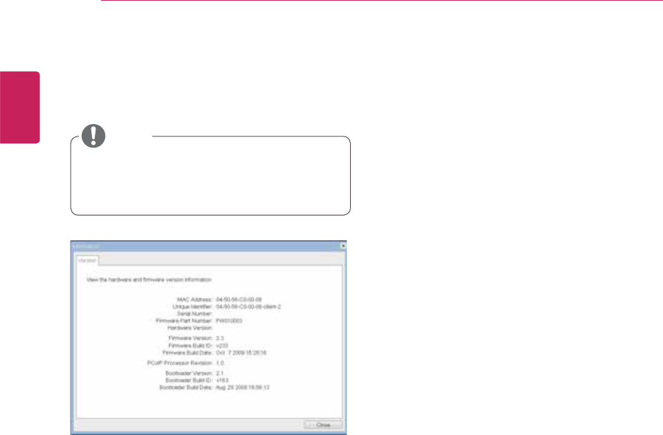
yVPD Information
The Vital Product Data (VPD) is information that
uniquely identifies each portal or host.
yMAC Address
The portal MAC address
yUnique Identifier
The portal ID
ySerial Number
The portal serial number
yFirmware Part Number
The part number of the PCoIP firmware
yHardware Version
The portal hardware version
yFirmware Information
The Firmware Information shows the details of the
current PCoIP firmware.
yFirmware Version
The current PCoIP firmware version
yFirmware Build ID
The current PCoIP firmware revision code
yFirmware Build Date
The current PCoIP firmware build date
yBoot Loader Information
The Boot Loader Information shows the details of
the current PCoIP boot loader.
yBoot Loader Version
The current PCoIP boot loader version
yBoot Loader Build ID
The current PCoIP boot loader revision code
yBoot Loader Build Date
The current PCoIP boot loader build date
yBoot Loader Information
The Boot Loader Information shows the details of
the current PCoIP boot loader.
yMouse
yKeyboard
yImage
yDisplay Topology
Figure 2-21. Version Configuration
Information Window
In the Information window, the administrator can
access the Version tab that contains the device
related information.
User Settings Window
In the User Settings window, the administrator can
access the tab to select the mouse and keyboard
and define the PCoIP image quality.
The User Settings window has the following tabs:
PCoIP Processor Revision
This shows the PCoIP processor's revision code.
TERA1x00 Revision A silicone is denoted by 0.0
and TERA1x00 Revision B silicone is denoted by
1.0.
y The version information can also be viewed
using the Webpage Administration Interface.
NOTE
41
ENG
English
Using PCoIP Solution
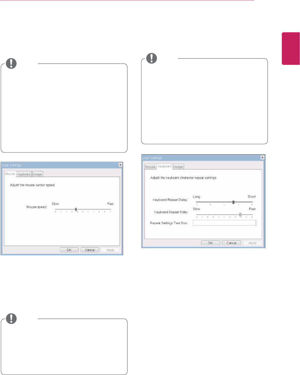
yMouse Speed
The Mouse Speed field allows the user to set the
portal's mouse cursor speed.
yKeyboard Repeat Delay
The Keyboard Repeat Delay field allows the user
to set the portal's keyboard repeat delay.
yKeyboard Repeat Rate
The Keyboard Repeat Rate field allows the user to
set the portal's keyboard repeat rate.
yRepeat Settings Test Box
The Repeat Settings Test Box allows the user to
test the selected keyboard settings.
Figure 2-22. Mouse
Figure 2-23. Keyboard
Mouse Tab
The Mouse tab allows the user to modify the OSD
and RDP session's mouse cursor speed setting.
Keyboard Tab
The Keyboard tab allows the user to modify the
OSD and RDP session's keyboard repeat setting.
y The OSD mouse cursor speed setting does
not affect the mouse cursor settings when
a PColP session is active unless the Local
Keyboard Host Driver function is being used
(see PColP Host Software User Guide for
more information).
y The Mouse tab has no corresponding menu
in the Webpage Administration Interface of
Section 1.
y The OSD keyboard setting does not affect
the keyboard settings when a PColP session
is active unless the Local Keyboard Host
Driver function is being used (see PColP
Host Software User Guide for more informa-
tion).
y The Keyboard tab has no corresponding
menu in the Webpage Administration Inter-
face of Section 1.
y The Mouse Speed can also be configured via
the PCoIP Host Software. For more informa-
tion on using the PCoIP Host Software, refer
to the PCoIP Host Software User Guide.
NOTE
NOTE
NOTE
42
ENG
English
Using PCoIP Solution
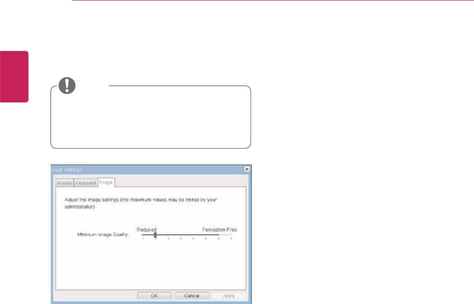
yMinimum Image Quality
The Minimum Image Quality slider allows the ad-
ministrator to make compromises between image
quality and frame rate when network bandwidth
is limited. Sometimes, lower-quality images at a
higher frame rate may be required, while at other
times, higher-quality images at a lower frame rate
may be preferred.
In environments where the network bandwidth is
limited, moving the slider towards Reduced en-
sures higher frame rates;
moving the slider towards Perception-Free ensures
higher image quality. When network bandwidth is
not limited, the PCoIP system will maintain percep-
tion-free quality regardless of the Minimum Image
Quality setting.
Figure 2-24. Image
Image
The Image tab allows a user to change the image
settings on the PCoIP system.
y The Image parameters can also be con-
figured using the Webpage Administration
Interface.
NOTE

Regulatory Information cont.
FCC Compliance Statement
This equipment has been tested and found to comply
within the limits of a Class B digital device pursuant to Part
15 of the FCC Rules. These limits are designed to provide
reasonable protection against harmful interference in a
residential installation.
This equipment generates, uses, and can radiate radio
frequency energy and if not installed and used in
accordance with the instructions, may cause harmful
interference to radio communications. However, there is
no guarantee that interference will not occur in a particular
installation.
If this equipment does cause harmful interference to radio
or television reception (which can be determined by
turning the equipment on and off), the user is encouraged
to try to correct the interference by using one or more of
the following measures:
Reorient or relocate the receiving antenna.
Increase the separation between the equipment and
the receiver.
Connect the equipment into an outlet on a circuit
different from that to which the receiver is connected.
Consult the dealer or an experienced radio/TV
technician for help.
Caution: Changes or modifications not expressly approved
by the party responsible for compliance could void the
user's (or your) authority to operate the equipment. Only
peripherals (digital input/output devices, terminals, printers,
etc.) certified to comply with the Class B limits may be
attached to this monitor. Operation with non-certified
peripherals is likely to result in interference to radio and TV
reception. Only shielded signal cables may be used with
this System.
Canadian DOC Notice
This Class B digital apparatus meets all requirements of
the Canadian Interference-Causing Equipment
Regulations. Cet appareil numérique de la classe B
respecte toutes les exigences du Règlement sur le
matériel brouilleur du Canada.
CE Conformity Notice
(for Europe)
Products with the “CE” Marking comply with the EMC
Directive(89/336/EEC) and LOW VOLTAGE Directive
(73/23/EEC) issued by the Commission of the European
Community.
Compiance with these directives implies conformity to the
following European Norms :
• EN 55022 ; Radio Frequency Interference
• EN 55024 ; Electromagnetic Immunity
• EN 61000-3-2 ; Power Line Harmonics
• EN 61000-3-3 ; Voltage Fluctuations
• EN 60950-1 ; Product Safety
Low Radiation Compliance (MPR II)
This monitor meets one of the strictest guidelines available
today for low radiation emissions, offering the user extra
shielding and an antistatic screen coating. These
guidelines, set forth by a government agency in Sweden,
limit the amount of emission allowed in the Extremely Low
Frequency (ELF) and Very Low Frequency (VLF)
electromagnetic range.
01
NOTICE
The regulations are applied only to the products with the
ID LABEL indicating specific requirements.
NOTICE
The regulations are applied only to the products with the
ID LABEL indicating specific requirements.
NOTICE
The regulations are applied only to the products with the
ID LABEL indicating specific requirements.
TCO'99 (TCO'99 applied model only)
Congratulations!
You have just purchased a TCO’99 approved and labelled
product! Your choice has provided you with a product
developed for professional use. Your purchase has also
contributed to reducing the burden on the environment and
also to the further development of environmentally
adapted electronics products.

Regulatory Information cont.
02
Why do we have environmentally labelled computers?
In many countries, environmental labelling has become an
established method for encouraging the adaptation of
goods and services to the environment. With the growing
manufacture and usage of electronic equipment
throughout the world, there is a recognized concern for the
materials and substances used by electronic products
with regards to their eventual recycling and disposal. By
proper selection of these materials and substances, the
impact on the environment can be minimized.
There are also other characteristics of a computer, such as
energy consumption levels, that are important from the
viewpoints of both the work (internal) and natural (external)
environments. Electronic equipment in offices is often left
running continuously, resulting in unnecessary
consumption of large amounts of energy and additional
power generation. From the standpoint of carbon dioxide
emissions alone, it is vital to save energy.
What does labelling involve?
The product meets the requirements for the TCO’99
scheme which provides for international and environmental
labelling of personal computers and/or displays.
The labelling scheme was developed as a joint effort by the
TCO (The Swedish Confederation of Professional
Employees), Svenska Naturskyddsforeningen
(The Swedish Society for Nature Conservation) and
Statens Energimyndighet (The Swedish National
Energy Administration).
Approval requirements cover a wide range of issues:
ecology, ergonomics, emission of electrical and magnetical
fields, energy consumption and electrical safety.
Ecological criteria impose restrictions on the presence and
use of heavy metals, brominated and chlorinated flame
retardants, and other substances. The product must be
prepared for recycling and the manufacturing site(s) shall
be certified according to ISO14001 or EMAS registered.
Energy requirements include a demand that the system
unit and/or display, after a certain period of inactivity,
shall reduce its power consumption to a lower level in one
or more stages. The length of time to reactivate the system
unit shall be reasonable for the user.
Labelled products must meet strict environmental
demands, for example, in respect of the reduction of
electrical and magnetical fields as well as work load and
visual ergonomics.
Below you will find a brief summary of the ecological
requirements met by this product. The complete
ecological criteria document can be found at TCO
Development’s website http://www.tcodevelopment.com
or may be ordered from:
TCO Development
SE-114 94 STOCKHOLM, Sweden
Fax: +46 8 782 92 07
Email : development@tco.se
Information regarding TCO’99 approved and labelled
products may also be obtained at
http://www.tcodevelopment.com
Ecological requirements
Flame retardants
Flame retardants may be present in printed wiring board
laminates, cables, and housings. Their purpose is to
prevent, or at least to delay the spread of fire. Up to 30%
by weight of the plastic in a computer casing can consist of
flame retardant substances. Many flame retardants
contain bromine or chlorine, and these flame retardants
are chemically related to PCBs (polychlorinated
biphenyls). Both the flame retardants containing bromine
or chlorine and the PCBs are suspected of giving rise to
health effects, including reproductive damage in fish-
eating birds and mammals, due to the bio-accumulative*
processes when not disposed of in accordance with strict
standards for disposal.
TCO’99 requires that plastic components weighing more
than 25 grams shall not contain flame retardants with
organically bound bromine or chlorine. Flame retardants
are allowed in the printed wiring board laminates due to
the lack of commercially available alternatives.
Cadmium**
Cadmium is present in rechargeable batteries and in the
colour-generating layers of certain computer displays.
TCO’99 requires that batteries, the colour-generating
layers of display screens, and the electrical or electronics
components shall not contain any cadmium.
Mercury**
Mercury is sometimes found in batteries, relays and
switches. TCO’99 requires that batteries shall not contain
any mercury. It also demands that mercury is not present
in any of the electrical or electronics components
associated with the labelled unit. There is however one
Regulatory Information cont.
03
exception. Mercury is, for the time being, permitted in the
back light system of flat panel monitors as there today is
no commercially available alternative. TCO aims on
removing this exception when a mercury free alternative is
available.
Lead**
Lead can be found in picture tubes, display screens,
solders and capacitors. TCO’99 permits the use of lead
due to the lack of commercially available alternatives, but
in future requirements TCO Development aims at
restricting the use of lead.
_____________________________________________
* Bio-accumulative is defined as substances which
accumulate in living organisms.
**Lead, Cadmium and Mercury are heavy metals
which are bio-accumulative.
TCO’03
(TCO’03 applied model only)
Congratulations!
The display you have just purchased carries the TCO’03
Displays label.
This means that your display is designed,manufactured
and tested according to some of the strictest quality and
environmental requirements in the world. This makes for a
high performance product, designed with the user in focus
that also minimizes the impact on our natural environment.
Some of the features of the TCO’03 Display requirements:
Ergonomics
• Good visual ergonomics and image quality in order to
improve the working environment for the user and to
reduce sight and strain problems. Important
parameters are luminance, contrast, resolution,
reflectance, colour rendition and image stability.
Energy
• Energy-saving mode after a certain time – beneficial
both for the user and the environment
• Electrical safety
Emissions
• Electromagnetic fields
• Noise emissions
Ecology
• The product must be prepared for recycling and the
manufacturer must have a certified environmental
management system such as EMAS or ISO 14 001
• Restrictions on
chlorinated and brominated flame retardants and
polymers
heavy metals such as cadmium, mercury and lead.
The requirements included in this label have been
developed by TCO Development in co-operation with
scientists, experts, users as well as manufacturers all over
the world. Since the end of the 1980s TCO has been
involved in influencing the development of IT equipment in
a more user-friendly direction. Our labelling system started
with displays in 1992 and is now requested by users and
IT-manufacturers all over the world.
For more information, please visit
www.tcodevelopment.com
Information for Environmental Preservation
LGE. announced the 'LG Declaration for a Cleaner
Environment' in 1994, and this ideal has served as a
guiding managerial principle ever since. The Declaration is
a foundation that has allowed us to undertake
environmentally friendly activities in careful consideration
of economic, environmental, and social aspects.
We promote activities for environmental preservation, and
we specifically develop our products to embrace the
concept of environment-friendly.
We minimize the hazardous materials contained in our
products. For example, there is no cadmium to be found in
our monitors.
Information for recycling
This monitor may contain parts which could be hazardous
to the environment. It is important that this monitor be
recycled after use.
LGE. handles all waste monitors through an
environmentally acceptable recycling method. There are
several take-back and recycling systems currently in
English
Regulatory Information cont.
04
operation worldwide. Many parts will be reused and
recycled, while harmful substances and heavy metals are
treated by an environmentally friendly method.
If you want to find out more information about our
recycling program, please contact your local LG vendor or
a corporate representative of LG.
We set our vision and policies on a cleaner world by
selecting the issue of the global environment as a task for
corporate improvement. Please visit our website for more
information about our ‘green’ policies.
http://www.lge.com/about/environment/html/Recycling.jsp
Informationen zur Erhaltung der Umwelt
Im Jahr 1994 verkündete LGE die 'LG Declaration for a
Cleaner Environment' (LG Erklärung für eine sauberere
Umwelt). Seitdem dient dieses Ideal als führendes Prinzip
des Unternehmens. Diese Erklärung war die Basis für die
Durchführung von
umweltfreundlichen Aktivitäten, wobei wirtschaftliche,
umweltbezogene und soziale Aspekte in die
Überlegungen mit einbezogen wurden.
Wir fördern Aktivitäten zum Schutz der Umwelt und die
Entwicklung unserer Produkte ist darauf ausgerichtet,
unserem Konzept bezüglich Umweltfreundlichkeit gerecht
zu werden.
Wir sind darauf bedacht, den Anteil der in unseren
Produkten enthaltenen schädlichen Materialien zu
minimieren. So ist in unseren Monitoren beispielsweise
kein Kadmium zu finden.
Informationen zum Thema Recycling
Dieser Monitor enthält Teile, die umweltschädlich sein
können. Es ist unbedingt erforderlich, dass der Monitor
recycelt wird, nachdem er außer Dienst gestellt wurde.
Bei LGE. werden alle ausrangierten Monitore in einem
unter umweltbezogenen Aspekten geeigneten Verfahren
recycelt. Augenblicklich sind weltweit mehrere
Rücknahme- und Recyclingsysteme im Einsatz. Viele
Teile werden wieder verwendet und recycelt. Schädliche
Substanzen und Schwermetalle werden durch
umweltverträgliche Verfahren behandelt.
Falls Sie mehr über unser Recyclingprogramm erfahren
möchten, wenden Sie sich bitte an Ihren lokalen LG-
Händler oder einen Unternehmensvertreter von LG.
Wir richten unsere Firmenpolitik auf eine sauberere
Umwelt hin aus, indem wir umweltspezifische Aspekte als
wichtigen Punkt in die Weiterentwicklung unseres
Unternehmens einfließen lassen. Zusätzliche
Informationen über unsere ‘grüne’ Firmenpolitik erhalten
Sie auf unserer Website.
http://www.lge.com/about/environment/html/Recycling.jsp
Information sur la protection del’environnement
LGE. a publié sa 'Déclaration en faveur d’un
environnement plus propre' en 1994 et celle-ci est restée,
depuis lors, un principe directeur de notre entreprise.
Cette déclaration a servi de base à notre réflexion et nous
a permis de prendre en compte à la fois les aspects
économiques et sociaux de nos activités, tout en
respectant l’environnement.
Nous encourageons les activités en faveur de la
préservation de l’environnement et c’est dans cet esprit
que nous développons nos produits : nous réduisons au
minimum les matières dangereuses qui entrent dans leur
composition et l’on ne trouve pas de cadmium, par
exemple, dans nos moniteurs.
Information sur le recyclage
Ce moniteur peut contenir des composants qui présentent
un risque pour l’environnement. Il est donc important que
celui-ci soit recyclé après usage.
LGE. traite les moniteurs en fin de cycle conformément à
une méthode de recyclage respectueuse de
l’environnement. Nous reprenons nos produits et les
recyclons dans plusieurs sites répartis dans le monde
entier. De nombreux composants sont réutilisés et
recyclés, et les matières dangereuses, ainsi que les
métaux lourds, sont traités selon un procédé écologique.
Si vous souhaitez plus de renseignements sur notre
programme de recyclage, veuillez contacter votre
revendeur LG ou un l’un de nos représentants.
Nous voulons agir pour un monde plus propre et croyons
au rôle de notre entreprise dans l’amélioration de
l’environnement. Pour plus de renseignements sur notre
politique “verte”, rendez visite à notre site :
http://www.lge.com/about/environment/html/Recycling.jsp
Deutsch
Français
05
Regulatory Information cont.
Informazioni per la tutela dell’ambiente
La LGE. ha annunciato nel 1994 la cosiddetta 'LG
Declaration for a Cleaner Environment' (Dichiarazione di
LG a favore di un ambiente più pulito), un ideale che da
allora funge da principio ispiratore della gestione
aziendale. La dichiarazione rappresenta il fondamento che
consente di intraprendere attività a favore dell'ambiente
tenendo conto degli aspetti economici, ambientali e
sociali.Noi della LG, promuoviamo attività a favore della
tutela dell'ambiente sviluppando appositamente i nostri
prodotti per cogliere il concetto del rispetto dell’ambiente
riducendo i materiali dannosi presenti nei nostri prodotti.
Ad esempio nei nostri monitor non è presente il cadmio.
Informazioni per il riciclaggio
Il monitor può presentare componenti che potrebbero
risultare eventualmente dannosi per l'ambiente. È
importante che il monitor sia riciclato al termine del suo
utilizzo.
La LGE. gestisce tutti i monitor di rifiuto con un metodo di
riciclaggio soddisfacente dal punto di vista ambientale. In
tutto il mondo sono attualmente in funzione numerosi
sistemi di riciclaggio e recupero. I diversi componenti sono
riutilizzati e riciclati, mentre le sostanze dannose e i metalli
pesanti vengono trattati con un metodo rispettoso
dell’ambiente.
Se si desiderano maggiori informazioni in merito al
programma di riciclaggio, è consigliabile rivolgersi al
proprio rivenditore LG o ad un rappresentante aziendale
della LG.
Noi della LG impostiamo la nostra visione e le nostre
politiche a favore di un mondo più pulito ponendo la
questione dell'ambiente dal punto di vista globale come
una mansione rivolta al miglioramento della nostra
azienda. Vi invitiamo a visitare il nostro sito internet per
ulteriori informazioni sulla nostra politica “verde”.
http://www.lge.com/about/environment/html/Recycling.jsp
Información para la conservación
medioambiental
LGE. presentó la 'Declaración para un entorno más limpio
de LG' en 1994 y este ideal ha servido para guiar nuestros
principios empresariales desde entonces. La Declaración
es la base que nos ha permitido llevar a cabo tareas que
respetan el medio ambiente siempre teniendo en cuenta
aspectos sociales,
económicos y medioambientales.
Promocionamos actividades orientadas a la conservación
del medio ambiente y desarrollamos nuestros productos
específicamente para que se ajusten a la filosofía que
protege el entorno.
Reducimos al máximo el uso de materiales de riesgo en
nuestros productos. Un ejemplo de ello es la ausencia
total de cadmio en nuestros monitores.
Información para el reciclaje
Este monitor puede contener piezas que entrañen riesgos
medioambientales. Es importante reciclar este monitor
después de su utilización.
LGE. trata todos los monitores usados siguiendo un
método de reciclaje que no daña al entorno. Contamos
con diversos sistemas de recuperación y reciclaje que
funcionan a nivel mundial en la actualidad. Es posible
reciclar y reutilizar muchas de las piezas, mientras que las
sustancias dañinas y los metales pesados se tratan
siguiendo un método que no perjudique al medio
ambiente. Si desea obtener más información acerca del
programa de reciclaje, póngase en contacto con su
proveedor local de LG o con un representante empresarial
de nuestra marca.
Basamos nuestra visión y nuestras políticas en un mundo
más limpio y para ellos optamos por un entorno global
como tarea principal de nuestra evolución como empresa.
Visite nuestra página Web para obtener más información
sobre nuestras políticas ecológicas.
http://www.lge.com/about/environment/html/Recycling.jsp
Informações relacionadas à preservação
ambiental
A LGE. anunciou a 'LG Declaration for a Cleaner
Environment' (Declaração da LG para um ambiente mais
limpo) em 1994 e esse ideal tem servido desde então
como um princípio administrativo de orientação. A
Declaração é a base que nos tem permitido realizar
atividades favoráveis ao ambiente com consideração
atenta aos aspectos econômicos, ambientais e sociais.
Promovemos atividades de preservação ambiental e
desenvolvemos nossos produtos para englobar
Italiano
Espanõl
Português
06
Regulatory Information cont.
especificamente o conceito de favorável ao ambiente.
Reduzimos os materiais perigosos contidos em nossos
produtos. Por exemplo, não há cádmio em nossos
monitores.
Informações relacionadas à reciclagem
Este monitor pode conter peças que podem representar
riscos ao ambiente. É importante que ele seja reciclado
após o uso.
A LGE. cuida de todos os monitores descartados através
de um método de reciclagem agradável ao ambiente. Há
vários sistemas de devolução e reciclagem atualmente
em operação no mundo. Muitas peças serão reutilizadas
e recicladas e as substâncias nocivas e os metais
pesados passarão por tratamento através de um método
favorável ao ambiente.
Para obter mais informações sobre nosso programa de
reciclagem, entre em contato com seu fornecedor LG
local ou com um representante corporativo da LG.
Definimos nossa visão e nossas políticas relacionadas a
um mundo mais limpo selecionando a questão do
ambiente global como uma tarefa de aprimoramento
corporativo. Visite nosso site para obter mais informações
sobre nossas políticas de meio ambiente.
http://www.lge.com/about/environment/html/Recycling.jsp
Informatie met betrekking tot het behoud van
het milieu
LGE. publiceerde in 1994 de 'LG Declaration for a Cleaner
Environment' (de LG-verklaring met betrekking tot een
schoner milieu). Deze verklaring en het ideaal van een
schoner milieu fungeren sindsdien als een bestuurlijke
leidraad voor onze onderneming. Op basis van deze
verklaring ontplooien wij milieuvriendelijke activiteiten,
waarbij er zowel met sociale en economische aspecten,
als met milieuaspecten zorgvuldig rekening wordt
gehouden.
Wij ondersteunen activiteiten die zijn gericht op het
behoud van het milieu en wij houden bij het ontwikkelen
onze producten specifiek rekening met de
milieuvriendelijkheid van onze producten.
Wij minimaliseren het gebruik van schadelijke stoffen in
onze producten. Er wordt bijvoorbeeld geen cadmium
verwerkt in onze monitors.
Nederlands
Informatie met betrekking tot recycling
Deze monitor bevat materialen die schadelijk zouden
kunnen zijn voor het milieu. Het is belangrijk dat deze
monitor aan het einde van zijn levensduur wordt
gerecycled.
LGE. verwerkt alle afvalmonitors via een milieuvriendelijke
recyclingmethode. Hiervoor worden er momenteel
wereldwijd verscheidene inname- en recyclingsystemen
gehanteerd. Een groot aantal onderdelen wordt opnieuw
gebruikt en gerecycled, waarbij schadelijke stoffen en
zware metalen volgens een milieuvriendelijke methode
worden verwerkt.
Voor meer informatie over ons recyclingprogramma kunt u
contact opnemen met uw plaatselijke LG-
vertegenwoordiger of een LG-vestiging.
Onze visie en ons beleid met betrekking tot een schonere
wereld vloeien voort uit het feit dat wij het milieu hebben
aangemerkt als een onderwerp dat speciale aandacht
verdient binnen onze onderneming. Bezoek onze website
voor meer informatie over ons 'groene' beleid.
http://www.lge.com/about/environment/html/Recycling.jsp
»ÌÙÓχˆËˇ ÔÓ Óı‡Ì ÓÍÛʇ˛˘ÂÈ Ò‰˚
¬ 1994 „Ó‰Û ÍÓÔÓ‡ˆËˇ LGE ÓÔÛ·ÎËÍÓ‚‡Î‡
'ƒÂÍ·‡ˆË˛ LG ÔÓ Óı‡Ì ÓÍÛʇ˛˘ÂÈ Ò‰˚',
ÍÓÚÓ‡ˇ Ò ÚÂı ÔÓ ÒÎÛÊËÚ ÓÒÌÓ‚Ì˚Ï ÔË̈ËÔÓÏ
ÛÔ‡‚ÎÂÌˡ. Õ‡ ÓÒÌÓ‚Â ˝ÚÓÈ ‰ÂÍ·‡ˆËË Ï˚ ÒÏÓ„ÎË
Ô‰ÔËÌˇÚ¸ ‰ÂÈÒڂˡ, Ó·ÂÒÔ˜˂‡˛˘ËÂ
·ÂÁÓÔ‡ÒÌÓÒÚ¸ ÓÍÛʇ˛˘ÂÈ Ò‰˚, Û‰ÂΡˇ ÔË ˝ÚÓÏ
‰ÓÎÊÌÓ ‚ÌËχÌË ˝ÍÓÌÓÏ˘ÂÒÍËÏ, ˝ÍÓÎӄ˘ÂÒÍËÏ Ë
ÒӈˇθÌ˚Ï ‡ÒÔÂÍÚ‡Ï.
Ã˚ ÒÚËÏÛÎËÛÂÏ ‰ÂˇÚÂθÌÓÒÚ¸ ÔÓ Óı‡ÌÂ
ÓÍÛʇ˛˘ÂÈ Ò‰˚, Û‰ÂΡˇ ÓÒÓ·Ó ‚ÌËχÌËÂ
‡Á‡·ÓÚÍ ̇¯ÂÈ ÔÓ‰Û͈ËË ‚ ÒÓÓÚ‚ÂÚÒÚ‚ËË Ò
ÍÓ̈ÂÔˆËÂÈ ˝ÍÓÎӄ˘ÂÒÍÓÈ ·ÂÁÓÔ‡ÒÌÓÒÚË.
Ã˚ Ò‚Ó‰ËÏ Í ÏËÌËÏÛÏÛ ÒÓ‰ÂʇÌË ÓÔ‡ÒÌ˚ı
‚¢ÂÒÚ‚ ‚ ̇¯ÂÈ ÔÓ‰Û͈ËË. Õ‡ÔËÏÂ, ‚ ̇¯Ëı
ÏÓÌËÚÓ‡ı ‚˚ Ì ̇ȉÂÚ ͇‰Ïˡ.
»ÌÙÓχˆËˇ ÔÓ ÛÚËÎËÁ‡ˆËË ÓÚıÓ‰Ó‚
›ÚÓÚ ÏÓÌËÚÓ ÏÓÊÂÚ ÒÓ‰Âʇڸ ÍÓÏÔÓÌÂÌÚ˚,
ÍÓÚÓ˚ ÏÓ„ÛÚ Ì‡ÌÂÒÚË Û˘Â· ÓÍÛʇ˛˘ÂÈ Ò‰Â.
Russian
07
Regulatory Information cont.
EPA
(EPA applied model only)
ENERGY STAR
is a set of power-saving guidelines
issued by the U.S. Environmental Protection
Agency(EPA).
NOM MARK (Mexico only)
ÕÂÓ·ıÓ‰ËÏÓ ÛÚËÎËÁËÓ‚‡Ú¸ ÏÓÌËÚÓ ÔÓÒÎÂ
ËÒÔÓθÁÓ‚‡Ìˡ.
KÓÔÓ‡ˆËˇ LGE Ô‡·‡Ú˚‚‡ÂÚ ‚Ò ·‡ÍÓ‚‡ÌÌ˚Â
ÏÓÌËÚÓ˚ Ò ÔÓÏÓ˘¸˛ ˝ÍÓÎӄ˘ÂÒÍË ÔËÂÏÎÂÏÓ„Ó
ÏÂÚÓ‰‡ ÛÚËÎËÁ‡ˆËË ÓÚıÓ‰Ó‚. œÓ ‚ÒÂÏÛ ÏËÛ
‰ÂÈÒÚ‚Û˛Ú ÒËÒÚÂÏ˚ ÛÚËÎËÁ‡ˆËË ÓÚıÓ‰Ó‚ Ë ‚ÓÁ‚‡Ú‡
ËÒÔÓθÁÓ‚‡ÌÌÓÈ ÔÓ‰Û͈ËË. ÃÌÓ„Ë ÍÓÏÔÓÌÂÌÚ˚
·Û‰ÛÚ ‚ÚÓ˘ÌÓ ËÒÔÓθÁÓ‚‡Ì˚ Ë ÛÚËÎËÁËÓ‚‡Ì˚, ‚ ÚÓ
‚ÂÏˇ Í‡Í ‚‰Ì˚ ‚¢ÂÒÚ‚‡ Ë ÚˇÊÂÎ˚ ÏÂÚ‡ÎÎ˚
·Û‰ÛÚ Ó·‡·ÓÚ‡Ì˚ Ò ÔÓÏÓ˘¸˛ ˝ÍÓÎӄ˘ÂÒÍË
ÔËÂÏÎÂÏÓ„Ó ÏÂÚÓ‰‡.
«‡ ·ÓΠÔÓ‰Ó·ÌÓÈ ËÌÙÓχˆËÂÈ ÔÓ Ì‡¯ÂÈ
ÔÓ„‡ÏÏ ÛÚËÎËÁ‡ˆËË ÓÚıÓ‰Ó‚ Ó·‡˘‡ÈÚÂÒ¸ Í
ÏÂÒÚÌÓÏÛ ÔÓÒÚ‡‚˘ËÍÛ ËÎË Ô‰ÒÚ‡‚ËÚÂβ
ÍÓÔÓ‡ˆËË LG.
Ã˚ ÓËÂÌÚËÛÂÏÒˇ ̇ Ó·ÂÒÔ˜ÂÌË ˝ÍÓÎӄ˘ÂÒÍÓÈ
·ÂÁÓÔ‡ÒÌÓÒÚË, ÒÚ‡‚ˇ Ò· ˆÂθ˛ „ÎÓ·‡Î¸ÌÛ˛ Á‡˘ËÚÛ
ÓÍÛʇ˛˘ÂÈ Ò‰˚. ƒÓÔÓÎÌËÚÂθÌÛ˛ ËÌÙÓχˆË˛
Ó Ì‡¯ÂÈ ÔÓÎËÚËÍ ÔÓ Óı‡Ì ÓÍÛʇ˛˘ÂÈ Ò‰˚ ‚˚
ÏÓÊÂÚ ̇ÈÚË Ì‡ ̇¯ÂÏ Ò‡ÈÚÂ:
http://www.lge.com/about/environment/html/Recycling.jsp
As an ENERGY STAR Partner LGE U. S.
A.,Inc. has determined that this product
meets the ENERGY STAR guidelines for
energy efficiency.
08
Regulatory Information cont.
1.When this crossed-out wheeled bin symbol is attached
to a product it means the product is covered by the
European Directive 2002/96/EC.
2.All electrical and electronic products should be
disposed of separately from the municipal waste
stream via designated collection facilities appointed by
the government or the local authorities.
3.The correct disposal of your old appliance will help
prevent potential negative consequences for the
environment and human health.
4.For more detailed information about disposal of your
old appliance, please contact your city office, waste
disposal service or the shop where you purchased the
product.
Disposal of your old appliance
1.Quando su un prodotto è riportato il simbolo di
1.När den här symbolen med en överkryssad
soptunna på hjul sitter på en produkt innebär det
att den regleras av European Directive
2002/96/EC.
2.Alla elektriska och elektroniska produkter bör
kasseras via andra vägar än de som finns för
hushållsavfall, helst via för ändamålet avsedda
uppsamlingsanläggningar som myndigheterna
utser.
3.Om du kasserar din gamla apparat på rätt sätt
så bidrar du till att förhindra negativa
konsekvenser för miljön och människors hälsa.
4.Mer detaljerad information om kassering av din
gamla apparat kan får av kommunen,
renhållningsverket eller den butik där du köpte
produkten.
1.Als het symbool met de doorgekruiste verrijdbare
afvalbak op een product staat, betekent dit dat
het product valt onder de Europese Richtlijn
2002/96/EC.
2.Elektrische en elektronische producten mogen
niet worden meegegeven met het huishoudelijk
afval, maar moeten worden ingeleverd bij
speciale inzamelingspunten die door de lokale of
landelijke overheid zijn aangewezen.
3.De correcte verwijdering van uw oude toestel
helpt negatieve gevolgen voor het milieu en de
menselijke gezondheid voorkomen.
Smaltimento delle apparecchiature obsolete
Kassering av din gamla apparat
Uw oude toestel wegdoen
1.Ce symbole, représentant une poubelle sur
roulettes barrée d'une croix, signifie que le
produit est couvert par la directive européenne
2002/96/EC.
2.Les éléments électriques et électroniques
doivent être jetés séparément, dans les vide-
ordures prévus à cet effet par votre municipalité.
3.Une élimination conforme aux instructions aidera
à réduire les conséquences négatives et risques
éventuels pour l'environnement et la santé
humaine.
4.Pour plus d'information concernant l'élimination
de votre ancien appareil, veuillez contacter votre
mairie, le service des ordures ménagères ou
encore la magasin où vous avez acheté ce
produit.
Élimination de votre ancien appareil
un bidone della spazzatura barrato da una croce
significa che il prodotto è coperto dalla direttiva
europea 2002/96/EC.
2.Tutti i prodotti elettrici ed elettronici dovrebbero
essere smaltiti separatamente rispetto alla
raccolta differenziata municipale, mediante
impianti di raccolta specifici designati dal
governo o dalle autorità locali.
3.Il corretto smaltimento delle apparecchiature
obsolete contribuisce a prevenire possibili
conseguenze negative sulla salute umana e
sull'ambiente.
4.Per informazioni più dettagliate sullo smaltimento
delle apparecchiature obsolete, contattare il
comune, il servizio di smaltimento rifiuti o il
negozio in cui è stato acquistato il prodotto.
English
French
Italian
Swedish
Dutch
WEEE (for Europe )

Regulatory Information cont.
09
1.Wenn dieses Symbol eines durchgestrichenen
Abfalleimers auf einem Produkt angebracht ist,
unterliegt dieses Produkt der europäischen
Richtlinie 2002/96/EC.
2.Alle Elektro- und Elektronik-Altgeräte müssen
getrennt vom Hausmüll über dafür staatlich
vorgesehenen Stellen entsorgt werden.
3.Mit der ordnungsgemäßen Entsorgung des alten
Geräts vermeiden Sie Umweltschäden und eine
Gefährdung der persönlichen Gesundheit.
4.Weitere Informationen zur Entsorgung des alten
Geräts erhalten Sie bei der Stadtverwaltung,
beim Entsorgungsamt oder in dem Geschäft, wo
Sie das Produkt erworben haben.
1.ŸÙ·Ó ¤Ó· ÚÔ˚fiÓ ‰È·ı¤ÙÂÈ ÙÔ ‰‡Ì‚ÔÏÔ ÂÓfi˜
‰È·ÁÚ·Ì̤ÓÔ˘ οϷıÔ˘ ·ÔÚÚÈÌÌ¿ÙˆÓ, ÙfiÙ ÙÔ ÚÔ˚fiÓ
ηχÙÂÙ·È ·fi ÙËÓ E˘Úˆ·˚΋ O‰ËÁ›· 2002/96/EOK.
2.H ·fiÚÚÈ„Ë fiÏˆÓ ÙˆÓ ËÏÂÎÙÚÈÎÒÓ Î·È ËÏÂÎÙÚÔÓÈÎÒÓ
ÚÔ˚fiÓÙˆÓ Ú¤ÂÈ Ó· Á›ÓÂÙ·È ¯ˆÚÈÛÙ¿ ·fi Ù· ÁÂÓÈο
ÔÈÎȷο ·ÔÚÚ›ÌÌ·Ù· ̤ۈ ηıÔÚÈṲ̂ӈÓ
ÂÁηٷÛÙ¿ÛÂˆÓ Û˘ÏÏÔÁ‹˜ ·ÔÚÚÈÌÌ¿ÙˆÓ, ÔÈ Ôԛ˜
¤¯Ô˘Ó ‰ËÌÈÔ˘ÚÁËı› ›Ù ·fi ÙËÓ Î˘‚¤ÚÓËÛË ‹ ·fi ÙȘ
ÙÔÈΤ˜ ·Ú¯¤˜.
3.H ÛˆÛÙ‹ ·fiÚÚÈ„Ë Ù˘ ·ÏÈ¿˜ Û·˜ Û˘Û΢‹˜ ı·
‚ÔËı‹ÛÂÈ ÛÙËÓ ·ÔÙÚÔ‹ Èı·ÓÒÓ ·ÚÓËÙÈÎÒÓ Û˘ÓÂÈÒÓ
ˆ˜ ÚÔ˜ ÙÔ ÂÚÈ‚¿ÏÏÔÓ Î·È ÙËÓ ˘Á›· ÙÔ˘ ·ÓıÚÒÔ˘.
4.°È· ÈÔ ÏÂÙÔÌÂÚ›˜ ÏËÚÔÊÔڛ˜ Û¯ÂÙÈο Ì ÙËÓ
·fiÚÚÈ„Ë Ù˘ ·ÏÈ¿˜ Û·˜ Û˘Û΢‹˜, ÂÈÎÔÈÓˆÓ‹ÛÙ ÌÂ
ÙÔ ·ÚÌfi‰›Ô ÙÔÈÎfi ÁÚ·Ê›Ô, ˘ËÚÂÛ›· ‰È¿ıÂÛ˘ ÔÈÎÈ·ÎÒÓ
·ÔÚÚÈÌÌ¿ÙˆÓ ‹ ÙÔ Ì·Á·Í› ·fi ÙÔ ÔÔ›Ô ·ÁÔÚ¿Û·ÙÂ ÙÔ
ÚÔ˚fiÓ.
1.Tämä merkki tuotteessa tarkoittaa, että tuote
kuuluu sähkö- ja elektroniikkalaiteromusta
annetun EU-direktiivin 2002/96/EY
soveltamisalaan.
2.Kaikki elektroniset laitteet ovat ongelmajätettä,
joten ne on toimitettava paikalliseen
keräyspisteeseen.
3.Vanhan laitteen asianmukainen hävittäminen
ehkäisee mahdollisia ympäristöön ja
terveyteen kohdistuvia haittavaikutuksia.
4.Lisätietoa vanhan laitteen hävittämisestä saat
ottamalla yhteyden paikallisiin viranomaisiin,
kierrätyskeskukseen tai myymälään, josta ostit
laitteen.
1.Når der er et tegn med et kryds over en
skraldespand, betyder det, at produktet er
omfattet af EU-direktiv 2002/96/EC.
2.Alle elektriske og elektroniske produkter skal
smides ud et andet sted end gennem den
kommunale affaldsordning ved hjælp af specielle
indsamlingsfaciliteter, der er organiseret af staten
1.Si en un producto aparece el símbolo de un contenedor
de basura tachado, significa que éste se acoge a la
Directiva 2002/96/CE.
2.Todos los aparatos eléctricos o electrónicos se deben
desechar de forma distinta del servicio municipal de
recogida de basura, a través de puntos de recogida
designados por el gobierno o las autoridades locales.
3.La correcta recogida y tratamiento de los dispositivos
inservibles contribuye a evitar riesgos potenciales para el
medio ambiente y la salud pública.
4.Para obtener más información sobre cómo deshacerse de
sus aparatos eléctricos y electrónicos viejos, póngase en
contacto con su ayuntamiento, el servicio de recogida de
basuras o el establecimiento donde adquirió el producto.
Vanhojen laitteiden hävittäminen
Entsorgung von Altgeräten
Sådan smider du dit gamle apparat ud
∞fiÚÚÈ„Ë Ù˘ ·ÏÈ¿˜ Û·˜ Û˘Û΢‹˜
Cómo deshacerse de aparatos eléctricos y
electrónicos viejos
eller de lokale myndigheder.
3.Korrekt bortskaffelse af dit gamle apparat er med
til at forhindre mulige skadevirkninger på miljøet
og menneskelig sundhed.
4.Mere detaljerede oplysninger om bortskaffelse af
dit gamle apparat kan fås ved at kontakte dit
lokale kommunekontor, renovationsselskab eller
den butik, hvor du købte produktet.
Finnish
German
Danish
Greek
Spanish
4.Wilt u meer informatie over de verwijdering van
uw oude toestel? Neem dan contact op met uw
gemeente, de afvalophaaldienst of de winkel
waar u het product hebt gekocht.
Regulatory Information cont.
10
Portuguese
Slovak
Czech
Croatian
Hungarian
Polish
Regulatory Information cont.
11
Estonian
Latvian
Lithuanian