LG Electronics USA N2210WZT Part15 Subpart B-LCD Monitor User Manual BEJN2210WZT 2
LG Electronics USA Part15 Subpart B-LCD Monitor BEJN2210WZT 2
Contents
- 1. BEJN2210WZT_User Manual 1
- 2. BEJN2210WZT_User Manual 2
- 3. BEJN2210WZT_User Manual 3
BEJN2210WZT_User Manual 2

www.lg.com
OWNER'S MANUAL
NETWORK MONITOR
N2210WZ
Please read the safety information carefully before using the product.
Network Monitor Model
English

2
ENG
English
Table of Contents
TABLE OF CONTENTS
3 ASSEMBLING AND
PREPARING
3 Unpacking
4 Partsandbuttons
6 SettingUptheMonitorset
6 - AttachingtheStandBase
6 - Detachingthestandbase
7 - Adjustingthestandheight
7 - Adjustingtheangle
8 - Mountingonatable
8 - UsingtheKensingtonlockingdevice
9 - Detachingthestandbody
9 - Swivelstand
9 - Installingthewallmountplate
10 - Mountingonawall
11 USING THE MONITOR SET
11 ConnectingInputSignalCable
11 - D-SUBINconnection-PC
11 - D-SUBOUTconnection-PCoIP
12 - DVIconnection-PCoIP
13 ConnectingLAN/Peripherals
13 - LANconnection-PCoIP
14 - Peripheraldeviceconnection
15 - SelfImageAdjustment
16 CUSTOMIZING SETTINGS
16 AccessingTheMainMenus
17 MENUSettings
17 - Picture
18 - Color
19 - Display
20 - Others
21 MODESettings
21 - F-ENGINE
22 - PHOTOEFFECT
23 AUTOSettings:D-SUBInput
23 -//-Settings:PCoIPInput
24 TROUBLESHOOTING
26 PRODUCT SPECIFICATION
27 PresetMode
27 PowerIndicator
28 PROPER POSTURE
28 Properpostureforusingthemonitor
29 USING PCOIP SOLUTION
19 -Volume

3
ENG
English
ASSEMBLING AND PREPARING
ASSEMBLING AND PREPARING
Unpacking
Pleasecheckwhetherallthecomponentsareincludedintheboxbeforeusingtheproduct.Ifthereare
missingcomponents,contacttheretailstorewhereyoupurchasedtheproduct.Notethattheproductand
componentsmaylookdifferentfromthoseshownhere.
OnlyuseanapprovedLGpoweradapter.
Damagecausedbyotherpoweradaptersisnotcoveredbywarranty.
Notethatthecomponentsmaylookdifferentfromthoseshownhere.
Withoutpriornotice,allinformationandspecificationsinthismanualaresubjecttochangetoimprove
theperformanceoftheproduct.
Topurchaseoptionalaccessories,visitanelectronicsstoreoronlineshoppingsiteorcontacttheretail
storewhereyoupurchasedtheproduct.
Power CordUser Manual/Card
Stand Base
Adaptor
CAUTION
NOTE
15-pin D-SUB Signal Cable
4
ENG
English
ASSEMBLING AND PREPARING
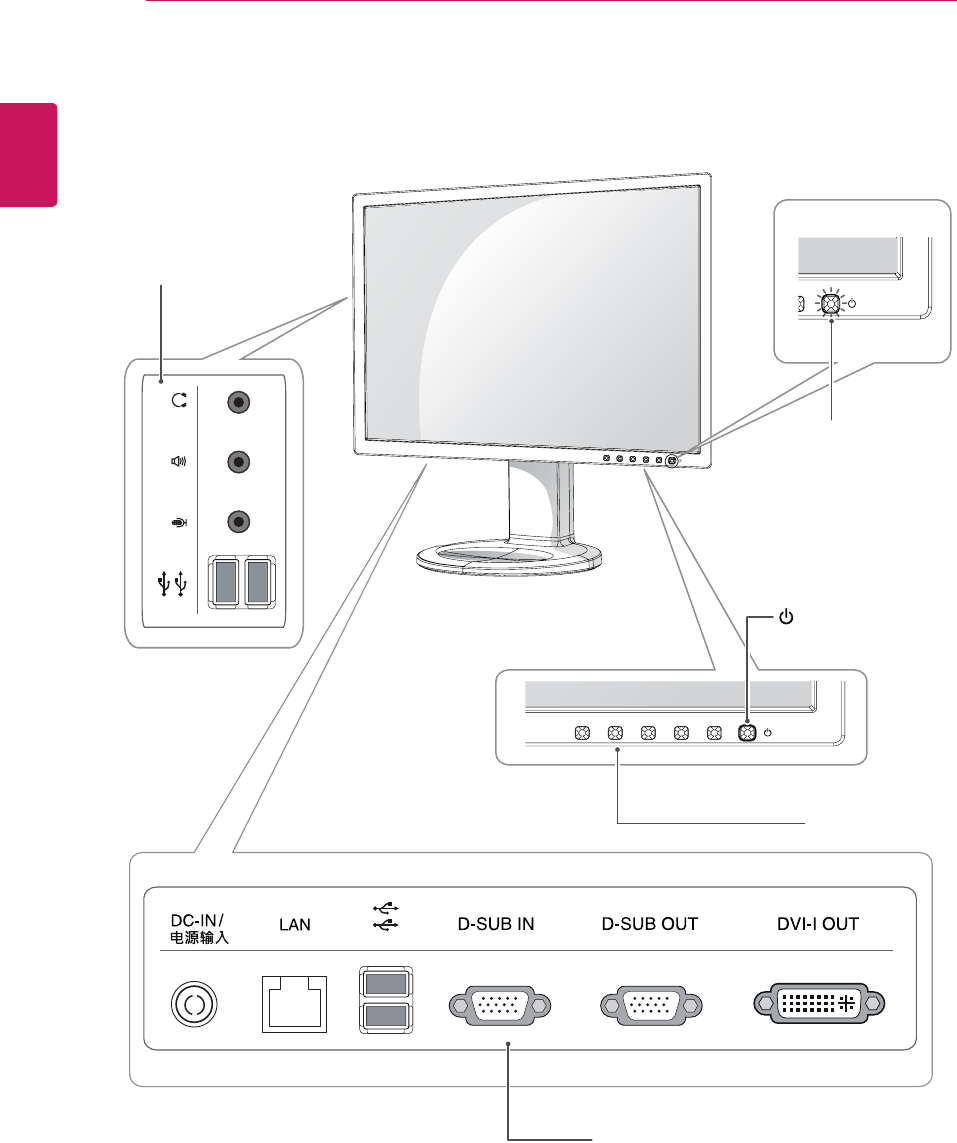
Parts and buttons
Power Indicator
LEDOn:Powerison
LEDOff:Powerisoff
FrontSideButtons
InputConnectors(Seep.11to14)
(PowerButton)
InputConnectors
(Seep.14)

5
ENG
English
ASSEMBLING AND PREPARING
Button Description
MENU Activatesthemainmenu.
OSD Lock/Unlock
Functions
Locks/unlockstheOSDscreen.
TolocktheOSDscreen,pressandholdtheMENUbutton
forseveralseconds.The"OSDLOCKED"messagewillbe
displayedandthescreenwillbelocked.
TounlocktheOSDscreen,pressandholdtheMENU
buttonagainforseveralseconds.The"OSDUNLOCKED"
messagewillbedisplayedandthescreenwillbeunlocked.
MODE MovestotheF-ENGINEandPHOTOEFFECToptions.
AUTO Toadjustthemonitorsettings,presstheAUTObuttonontheMONITORSETUPOSD
menu(onlysupportedforanalogsignal).
Foroptimalscreendisplay,usethefollowingresolution.
Optimal Resolution 1680x1050
INPUT Allowsselectionoftheinputsignal.
IfyouconnectthemonitortoacomputerusingaD-SUBcable,selecteitherthePCoIP
orD-SUBinputsignal.
Ifonlyonecomputerisconnectedtothemonitor,theinputsignalisdetectedautomati-
cally.TheinitialinputsignalisPCoIP.
EXIT ExitstheOSDmenu.
(PowerButton)
D-SUBInput:PowerOn/Off
PCoIPInput
MonitorOff:Pressthepowerbuttontwice,orpressthepowerbuttonandwaitfor10
seconds.
PCoIPOff:Pressthepowerbutton,thenpresstheEXITbuttonlocatednexttothe
powerbutton.
PCoIPOn:Pressthepowerbutton.
RemotePCPowerControl:Pressthepowerbuttonforatleastfivesecondstoturn
thePCon/off.
*TousetheRemotePCPowerControlfunction,separatesettingsarerequiredforthePC.
Power Indicator Whenthemonitorisinoperatingmode,thepowerindicator
willturnwhite(onmode).
Whenthemonitorisinpowersavingmode,thepowerindica-
torwillblinkwhite.
6
ENG
English
ASSEMBLING AND PREPARING
Thecomponentsappearingintheillustra-
tionsmaylookdifferentfromtheactualprod-
uct.
Donotcarrythemonitorupside-downasthis
maycauseittofalloffitsstand,resultingin
damageorinjury.
Toavoiddamagingthescreenwhenlifting
ormovingthemonitor,onlyholdthestandor
theplasticcover.Thisavoidsputtingunnec-
essarypressureonthescreen.
Onlyremovethetapeandthelockingpin
whenthemonitorismountedonthestand
baseandisinanuprightposition.Otherwise,
thestandbodymayprotrude,whichmay
leadtoinjury.
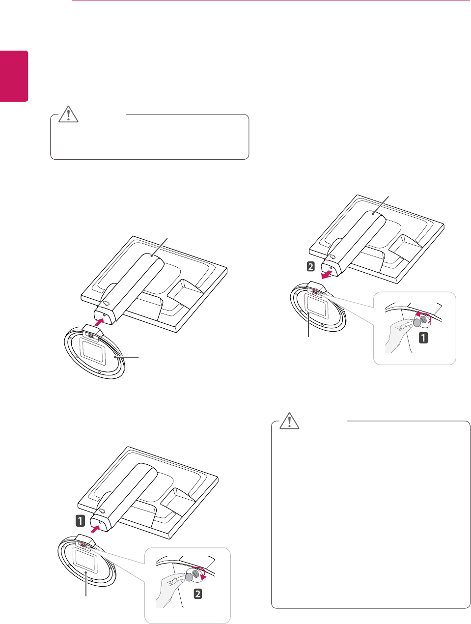
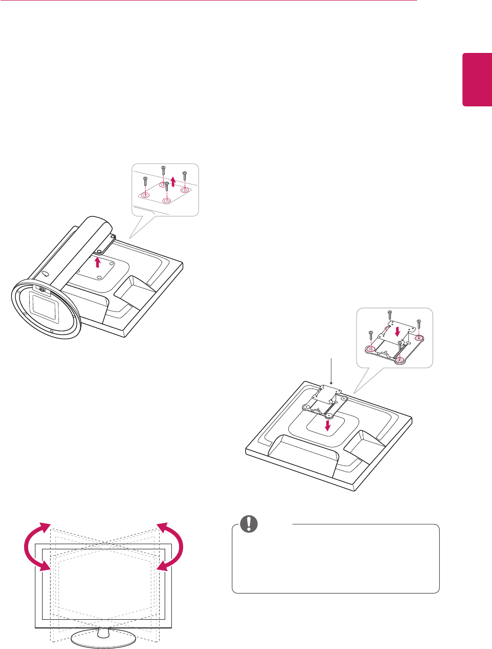
Detaching the stand base
1 Placethemonitor'sscreenfacedown.
Toprotectthescreenfromscratches,coverthe
surfacewithasoftcloth.
Setting Up the Monitor set
Attaching the Stand Base
1 Placethemonitor'sscreenfacedown.
Toprotectthescreenfromscratches,cover
thesurfacewithasoftcloth.
3 Usingacoin,turnthescrewclockwisetose-
cure the stand base.
2 Checktheposition (at the front and rear) of
thestandbody, then mountthestand baseon
thestand body asshowninthefigure.
Stand Body
Stand Base
Stand Base
2 Usingacoin,turnthescrewinthestandbase
counterclockwise.Detachthestand base from
thestand body.
Stand Body
Stand Base
CAUTION
CAUTION
7
ENG
English
ASSEMBLING AND PREPARING
Oncethepinisremoved,itisnotnecessary
tore-insertittoadjusttheheight.
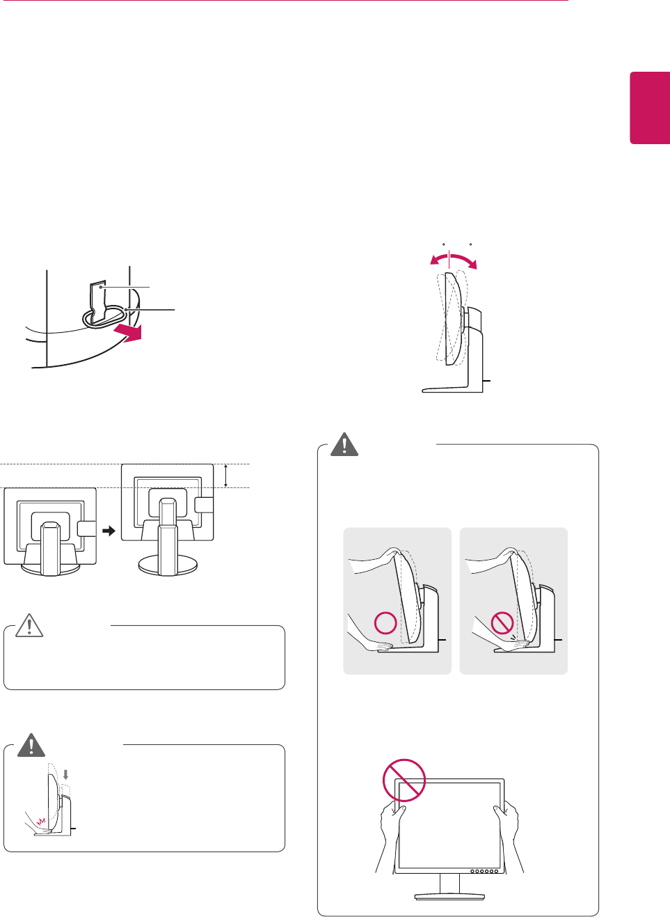
Adjusting the stand height
1 Placethemonitormountedonthestandbase
inanuprightposition.
Adjusting the angle
1 Placethemonitormountedonthestandbase
inanuprightposition.
2 Removethetapeattachedatthebottomrear
ofthe stand body, thenpulloutthelocking
pin.
3 Theheightcanbeadjustedupto110 mm.
2 Adjusttheangleofthescreen.Theangleofthe
screencanbeadjustedupto15°forwardsand
5°backwardsforacomfortableviewingexperi-
ence.
Toavoidinjurytothefingerswhenadjusting
thescreen,donotholdthelowerpartofthe
monitor'sframeasillustratedbelow.
Donotputyourfingerbe-
tweenthescreenandthe
base(chassis)whenadjust-
ingthescreen'sheight.
Becarefulnottotouchorpressthescreen
areawhenadjustingtheangleofthemonitor.
15- 5
Front Side Rear Side
15- 5
Tape
Locking Pin
Stand Body
110.0 mm
CAUTION
WARNING
WARNING
8
ENG
English
ASSEMBLING AND PREPARING
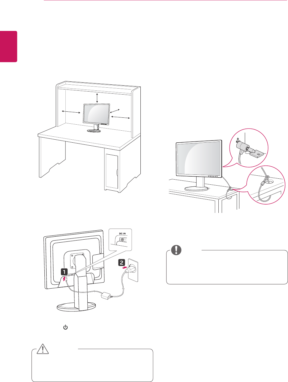
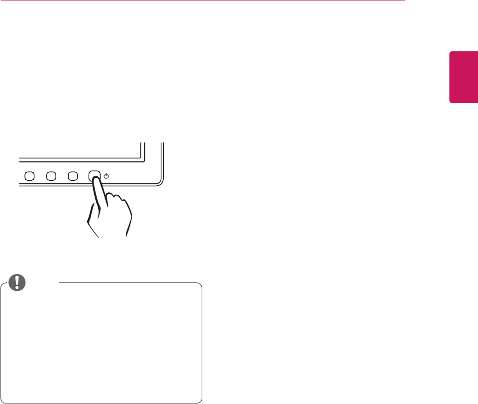
Mounting on a table
1 Liftthemonitorandplaceitonthetableinan
uprightposition.
Installatleast10 cm awayfromthewallto
ensuresufficientventilation.
2 Connecttheadaptortothemonitor,thenplug
thepowercordintothewalloutlet.
3 Pressthe (Power)buttononthefrontofthe
monitortoturnonthemonitor.
10 cm
10 cm
10 cm
10 cm
Unplugthepowercordpriortomovingor
installingthemonitor.Thereisriskofelectric
shock.
Using the Kensington locking
device
TheconnectorfortheKensingtonlockislocated
ontherearofthemonitor.
Formoreinformationoninstallationandusage,
refertotheKensingtonlockusermanualorvisit
thewebsiteathttp://www.kensington.com.
ConnectthemonitortothetablewiththeKensing-
tonlockcable.
UsingtheKensingtonlockisoptional.The
accessoriescanbepurchasedatyourlocal
electronicsstore.
CAUTION
NOTE
9
ENG
English
ASSEMBLING AND PREPARING
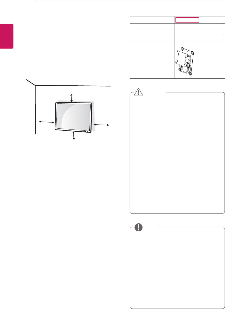
Installing the wall mount plate
ThismonitorhasaVESAcompatiblemountonthe
back.MostmountswillrequireanLGmounting
plate.
Detaching the stand body
1 Placethemonitor'sscreenfacedown.To
protectthescreenfromscratches,coverthe
surfacewithasoftcloth.
2 Usingascrewdriver,removethefourscrews
anddetachthestandfromthemonitor.
Swivel stand
ImageshownmaydifferfromyourMonitor
set.
1 Swivel356degreesandadjusttheangleofthe
Monitorsettosuityourview.
1 Placethemonitor'sscreenfacedown.To
protectthescreenfromscratches,coverthe
surfacewithasoftcloth.
2 Placethewallmountplateonthemonitorand
alignitwiththescrewholesonthemonitor.
3 Usingascrewdriver,tightenthefourscrewsto
fixtheplateontothemonitor.
Thewallmountplateissoldseparately.
Formoreinformationontheinstallation,refer
tothewallmountplate'sinstallationguide.
Wall Mount Plate
NOTE
10/100/1000MbpsRJ45(PCoIP)
10
ENG
English
ASSEMBLING AND PREPARING
10 cm
10 cm
10 cm 10 cm
Unplugthepowercordbeforemovingorin-
stallingthemonitortoavoidelectricshocks.
Installingthemonitorontheceilingorona
slantedwallmayresultinthemonitorfalling
off,whichcouldleadtoinjury.Pleaseuse
aLGwallmountingbracketwhenusinga
VESAmount.Formoreinformation,contact
yourlocalretailstoreoraqualifiedinstaller.
Applyingexcessiveforcewhenfastening
screwsmaycausedamagetothemoni-
tor.Damagecausedinthiswaywillnotbe
coveredbytheproductwarranty.
Usethewallmountingbracketandscrews
thatconformtotheVESAstandard.Dam-
agecausedbytheuseormisuseofinap-
propriatecomponentswillnotbecovered
bytheproductwarranty.
UsethescrewsspecifiedintheVESAstan-
dard.
Thewallmountkitincludestheinstallation
guideandnecessaryparts.
Thewallmountingbracketisoptional.The
accessoriescanbepurchasedatyourlocal
retailstore.
Thelengthofthescrewmaydifferforeach
wallmountingbracket.Ensurethecorrect
lengthofthescrewisused.
Formoreinformation,pleaserefertotheuser
manualforthewallmountingbracket.
Model N2210WZ
VESA (A x B) 75x75
Stand Screw M4
Required Screw 4
Wall Mount Plate
(Optional)
RW120
Mounting on a wall
Installthemonitoratleast10cmawayfromthe
wallandleaveabout10cmofspaceateachside
ofthemonitortoensuresufficientventilation.De-
tailedinstallationinstructionscanbeobtainedfrom
yourlocalretailstore.Pleaserefertothemanual
toinstallandsetupatiltingwallmountingbracket.
CAUTION
NOTE
If you intend to mount the Monitor set to a wall,
attach Wall mounting interface (optional parts) to
the back of the set.
When you install the Monitor set using a wall
mounting interface (optional parts), attach it
carefully so it will not drop.
1 Please, Use the screw and wall mount interface
in accordance with VESA Standards.
2 If you use screw longer than standard, the
monitor might be damaged internally.
3 If you use improper screw, the product might be
damaged and drop from mounted position. In
this case, LG Electronics is not responsible for
it.
4 VESA compatible.
5 Please use VESA standard as below.
y784.8 mm (30.9 inch) and under
* Wall Mount Pad Thickness : 2.6 mm
* Screw : Φ 4.0 mm x Pitch 0.7 mm x
Length 10 mm
y787.4 mm (31.0 inch) and above
* Please use VESA standard wall mount pad
and screws.

11
ENG
English
USING THE MONITOR SET
USING THE MONITOR SET
Connecting Input Signal Cable
Thismonitorsupportsthe*PlugandPlay
feature.
*PlugandPlay:Afeaturethatallowsyouto
addadevicetoyourcomputer,withouthaving
toreconfigureanythingorinstallanymanual
drivers.
D-SUB IN connection - PC
D-SUBINtransfersanalogvideosignalsfromthe
PCtothemonitor.
ConnectthemonitortothePCusingtheprovided
15-pinD-SUBsignalcableasillustratedbelow.
MacintoshAdaptor:UsethestandardMa-
cintoshadaptor.Othercommercialadaptors
maynotbecompatible(duetothesignaling
difference).
WhenusingaMacintoshD-SUBinputcable
Whenusingthisdevicesimplyasaregu-
larmonitorthroughtheRGBINport,set
"PCoIP"toOFFinMENU>OTHERSto
reduceenergyconsumption.
NOTE
NOTE
RGB OUT
RGB IN
MONITOR
RGB OUT
RGB IN
MONITOR
D-SUB OUT connection - PCoIP
D-SUBOUTcanonlymirrortheimagedisplayed
onthemonitor.(itdoesnotsupportanextended
desktop).
ConnectthemonitortothePCusingtheprovided
15-pinD-SUBsignalcableasillustratedbelow.
12
ENG
English
USING THE MONITOR SET
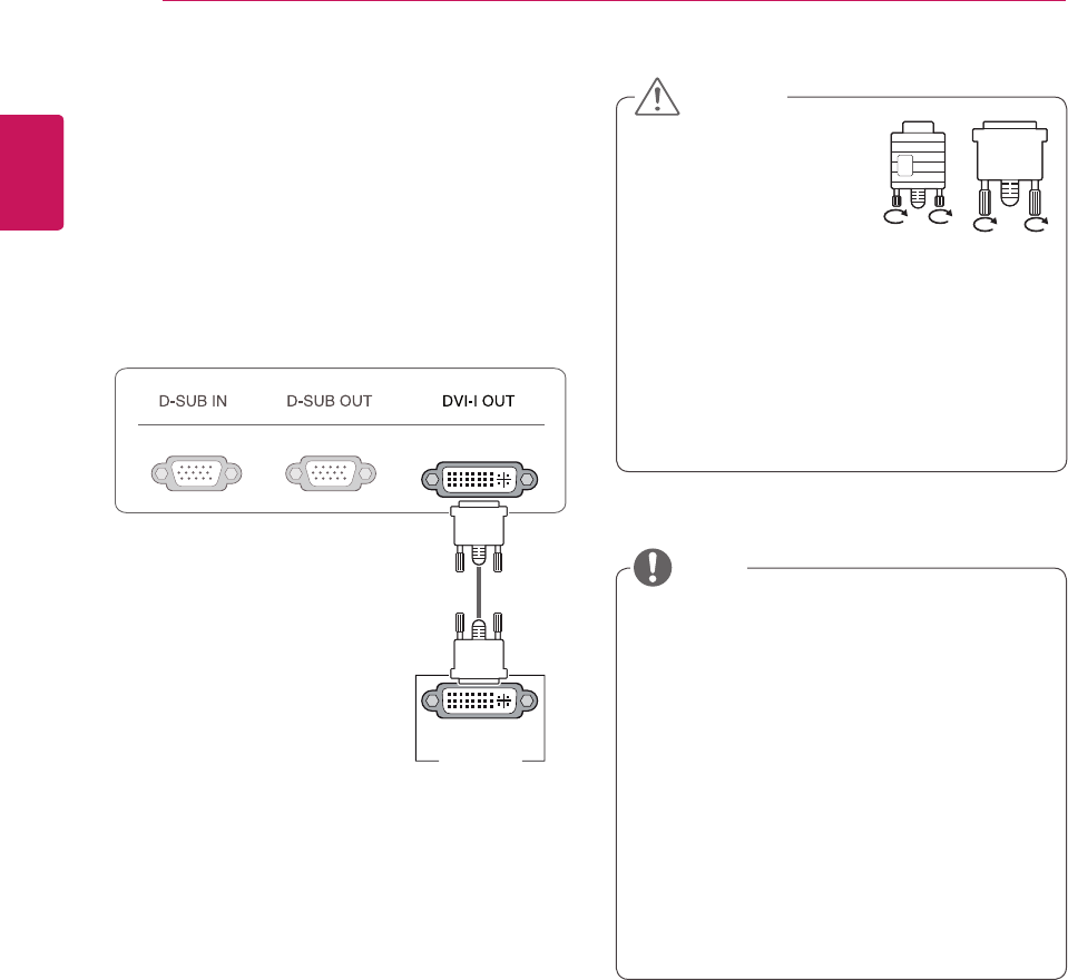
DVI connection - PCoIP
Transfersdigitalvideosignalstoanothermonitor.
ConnectthemonitorusingtheDVIcableasillus-
tratedbelow.
Thisconnectionisusedtosupportanextended
monitororreplicatetheimagedisplayedonthe
monitor.
Toconnectthemonitortoacomputer,use
theappropriatesignalcable(LANandD-
SUB).
AconvertercanbeusedtoconverttheDVI-I
inputsignaltoD-SUBinputsignal.
Whenconnectingthepowercordtotheout-
let,useagrounded(3-hole)multi-socketora
groundedwalloutlet.
Themonitormayflickerwhenturnedoninan
areaoflowtemperature.Thisisnormal.
Sometimesred,greenorbluespotsmayap-
pearonthescreen.Thisisnormal.
Connecttheinputsignal
cableandtighteninthe
directionofthearrow.To
preventdisconnection
securethecabletightly.
Donotpressonthescreenforaprolonged
time.Thismaycauseimagedistortion.
Donotdisplayastillimageonthescreen
foraprolongedtime.Thismaycauseimage
retention.Ifpossible,usethescreensaver.
DVI-I(D) IN
MONITOR
CAUTION
NOTE
13
ENG
English
USING THE MONITOR SET
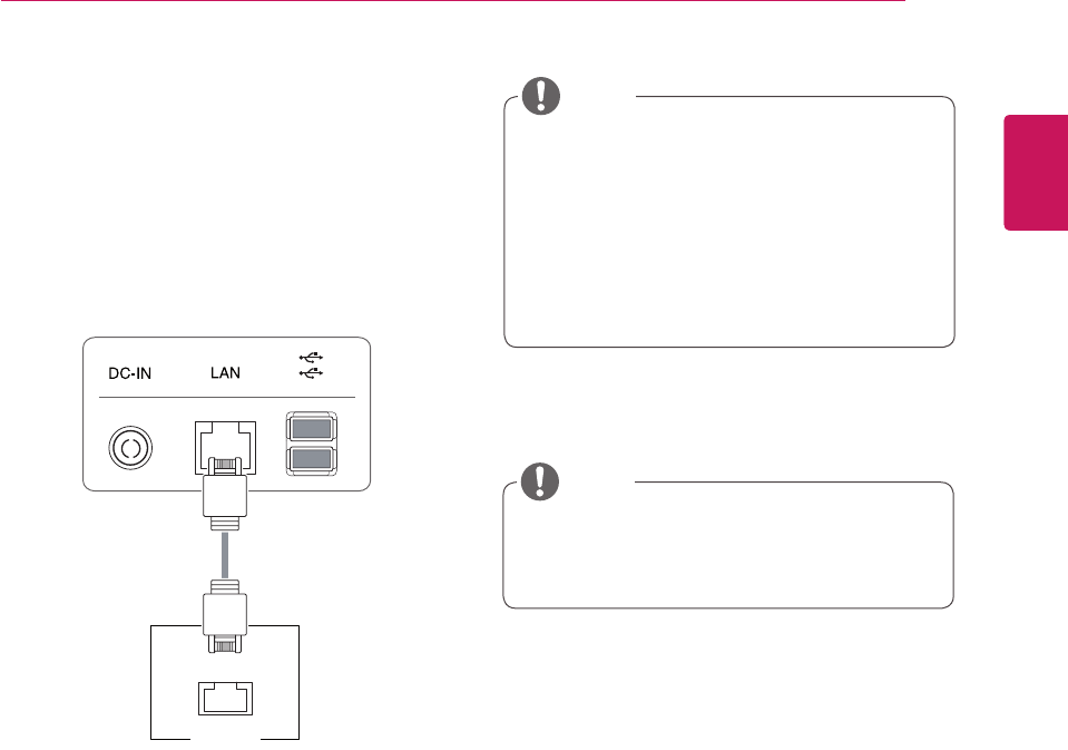
Connecting LAN/Peripherals
LAN connection - PCoIP
TheLANconnectiontransmitsPCoIPsignalsto
themonitor.Connecttherouterorswitchtothe
monitorusingaLANcableasillustratedbelow.
TheLANcableissoldseparately.
ThefollowingLANcabletypecanbeused:
Standard:IEEE802.3ETHERNET
WhenconnectingtheEarphoneOutorLine
OutthroughtheLAN,usethevolumeiconon
thetaskbarofyourPCtoadjustthevolume.
ConnecttheLANcableandtheperipheral
devicespriortobootingupthePC.
LAN
Hub/Router
NOTE
NOTE
14
ENG
English
USING THE MONITOR SET
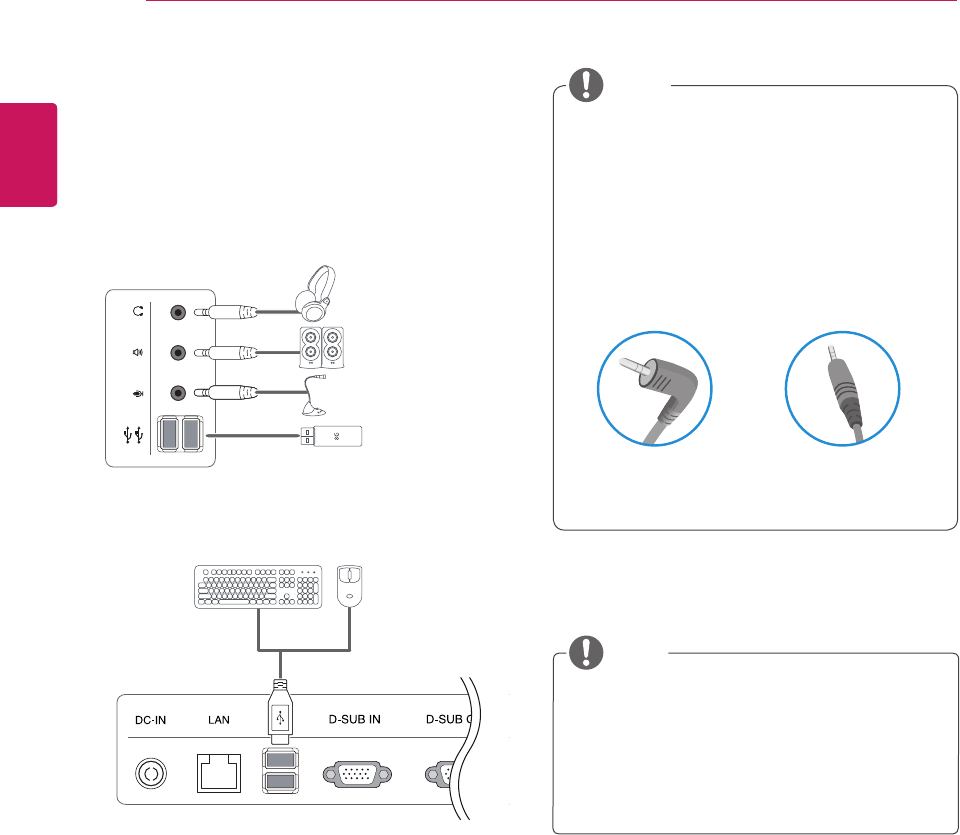
Peripheraldevicesaresoldseparately.
TheUSBportsontheleftandbottomofthe
monitorcanbeusedtoconnectthekey-
board,mouse,andotherUSBdevices.
Cableswithangledplugsmayhaveclear-
anceissues,usestraightplugswhenpos-
sible.
AngleType StraightType
Peripheral device connection
Connectperipheraldevicestothemonitorusing
USB,headphone,speaker,andmicrophoneports.
Left
Bottom
NOTE
NOTE
Headphones,speakersormicrophonemay
notworknormally,dependingontheserver
PCsettings.
Virtualsolutionsmayaffectthefunctionsor
speedofthespecificUSBstoragedevice.
15
ENG
English
USING THE MONITOR SET
Whatis"SelfImageAdjustment"?Thisfunc-
tionrunswhenthemonitorisconnectedfor
thefirsttimeandperformsautomaticimage
adjustmentforeachsignal(onlyavailablefor
analog[D-SUBinput]signals)toprovidean
optimalscreendisplay.
Self Image Adjustment
Pressthepowerbuttononthefronttoturnon
themonitor.Whenpoweredon,the"Self Image
Adjustment" functionwillrunautomatically(only
availableforanalog[D-SUBinput]signals).
NOTE
16
ENG
English
CUSTOMIZING SETTINGS
MENU MODE INPUT EXIT
MONITORSETUP
CUSTOMIZING SETTINGS
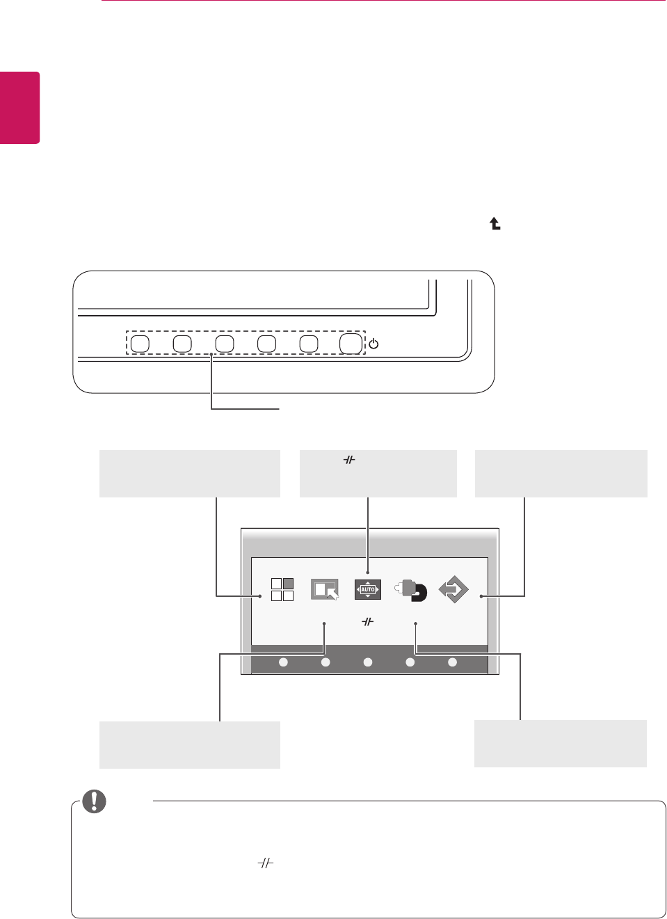
Accessing The Main Menus
1 PressanybuttononthefrontofthemonitortodisplaytheMONITORSETUPOSDmenu.
2 Presstoselectthedesiredmenuitem.
3 Tochangethesettingsoftheselecteditempressthebuttonsonthefrontofthemonitor.
Toreturntotheuppermenuorsetothermenuitems,usetheuparrow( )button.
4 SelectEXITtoleavetheOSDmenu.
MENU (See p.17)
Setsthescreenoptions.
EXIT(See p.5)
ExitstheOSDmenu.
AUTO /
(See p.23)
Optimizestheresolution.
/Disconnectsfromtheserver.
Differentmenuitemsareenableddependingonthetypeofinputsignal.
D-SUB Input: MENU,MODE,AUTO,INPUT,EXIT
PCoIP Input: MENU,MODE, ,INPUT,EXIT
Thelanguageofthemonitor'sOSDmenuandthatoftheOSDmenuillustratedintheCD-ROM
manualmaybedifferent.
Front Side Buttons
MODE (See p.21)
Setsthescreenmode.
INPUT (See p.5)
Setstheexternalinput.
NOTE
AUTO
17
ENG
English
CUSTOMIZING SETTINGS
MENU Settings
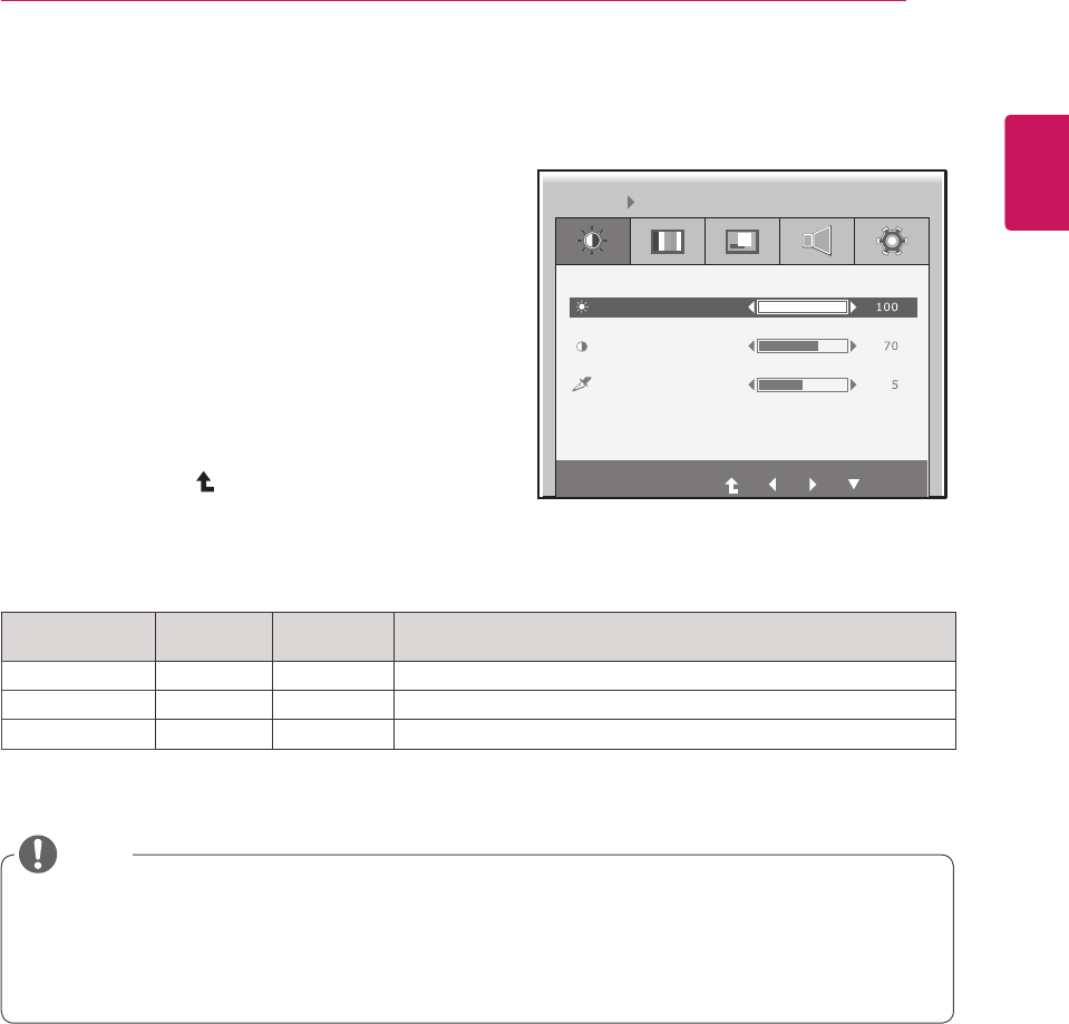
Picture
1 Pressanybuttononthefrontofthemonitortodis-
playtheMONITOR SETUP OSDmenu.
2 PresstheMENU buttontodisplaytheoptionsinthe
OSDmenu.
3 Settheoptionsbypressingthebuttonsonthefront
ofthemonitor.
4 SelectEXITtoleavetheOSDmenu.
Toreturntotheuppermenuorsetothermenuitems,
usetheuparrow( )button.
Eachoptionisexplainedbelow.
Menu Analog
(D-SUB)
PCoIP Description
BRIGHTNESS ● ● Setsthebrightnessofthescreen.
CONTRAST ● ● Setsthecontrastofthescreen.
SHARPNESS ● ● Setsthesharpnessofthescreen.
Ifthescreenisnotdisplayedproperlyafteradjustingthesettings,usethe"FACTORYRESET"
optiontorevertbacktothefactorydefaultsettings.Ifnecessary,enablethe"WHITEBALANCE"
optionagain.Thisoptionisenabledonlyforanalog(D-SUB)signals.
Analog: D-SUB (analog signal) input. PCoIP: Internal signal through the LAN.
BRIGHTNESS
CONTRAST
MENU PICTURE
SHARPNESS
EXIT
NOTE
18
ENG
English
CUSTOMIZING SETTINGS
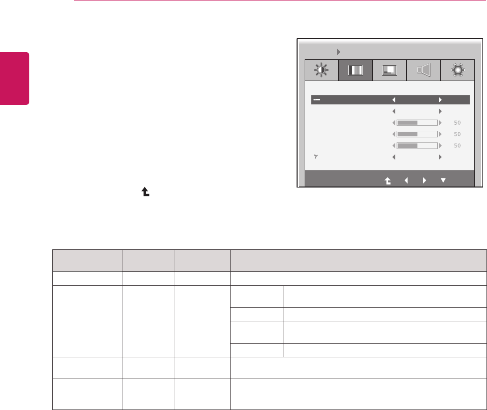
Menu Analog
(D-SUB)
PCoIP Description
COLOR TEMP ● ● AllowsPRESETorUSERtobeselected.
PRESET
● ●
sRGB SetsthescreencoloraccordingtothesRGBcolor
standard.
WARM Setsthescreencolortoareddishtone.
MEDIUM Setsthescreencolorbetweenthereddishandbluish
tone.
COOL Setsthescreencolortoabluishtone.
USER ● x YoucancustomizethepicturecolorusingRed,Green,andBlue
colors.
GAMMA
● ●
Setstheclarityofthescreen.
Thegammavaluecanbesetto0,1or2,fromdarkertobrighter
screencolorsrespectively.
Analog: D-SUB (analog signal) input. PCoIP: Internal signal through the LAN.
Color
1 Pressanybuttononthefrontofthemonitortodis-
playtheMONITOR SETUP OSDmenu.
2 PresstheMENU buttontodisplaytheoptionsinthe
OSDmenu.
3 Settheoptionsbypressingthebuttonsonthefront
ofthemonitor.
4 SelectEXIT toleavetheOSDmenu.
Toreturntotheuppermenuorsetothermenuitems,
usetheuparrow( )button.
Eachoptionisexplainedbelow.
COLOR TEMP PRESET
PRESET
GAMMA GAMMA 1
RED
GREEN
BLUE
WARM
MENU COLOR
EXIT
19
ENG
English
CUSTOMIZING SETTINGS
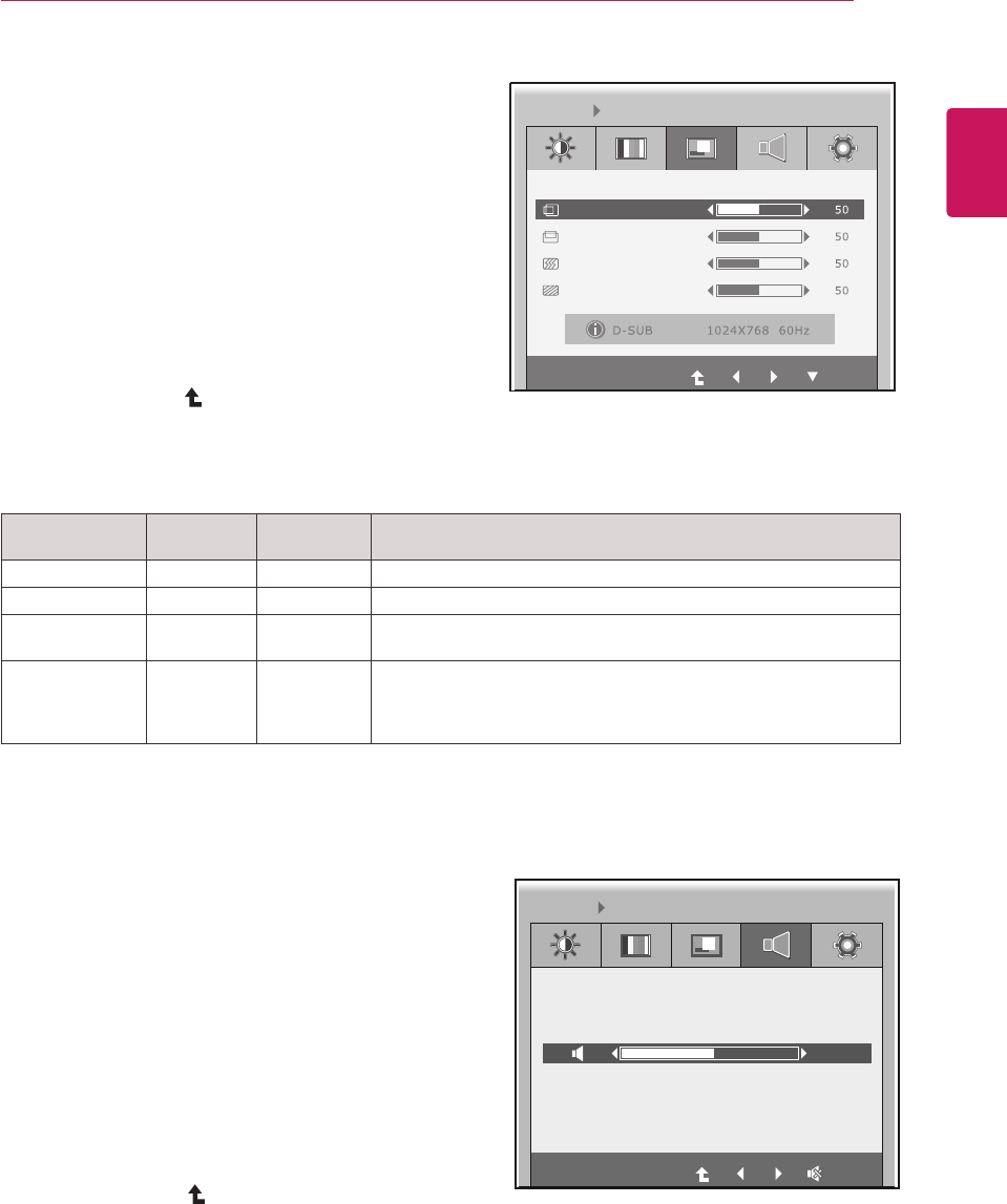
Menu Analog
(D-SUB)
PCoIP Description
HORIZONTAL ●xMovesthedisplayarealeftorright.
VERTICAL ●xMovesthedisplayareaupordown.
CLOCK ●xIfverticallinesareshownonthescreen,adjustthefrequencytomini-
mizethelinesandadjustthescreen'shorizontalwidth.
PHASE
●x
Adjuststhefocusofthescreen'simage.
Usewhenfrequenciesareshownonthescreenorwhenthetextap-
pearsoverlapped.Foroptimalresults,usethisoptionafteradjusting
the"CLOCK"option.
Analog: D-SUB (analog signal) input. PCoIP: Internal signal through the LAN.
Display
1 Pressanybuttononthefrontofthemonitortodis-
playtheMONITOR SETUP OSDmenu.
2 PresstheMENU buttontodisplaytheoptionsinthe
OSDmenu.
3 Settheoptionsbypressingthebuttonsonthefront
ofthemonitor.
4 SelectEXITtoleavetheOSDmenu.
Toreturntotheuppermenuorsetothermenuitems,
usetheuparrow( )button.
Eachoptionisexplainedbelow.
HORIZONTAL
EXIT
VERTICAL
CLOCK
PHASE
MENU DISPLAY
Volume
1 Pressanybuttononthefrontofthemonitortodis-
playtheMONITOR SETUP OSDmenu.
2 PresstheMENU buttontodisplaytheoptionsinthe
OSDmenu.
3 Settheoptionsbypressingthebuttonsonthefront
ofthemonitor.
4 SelectEXITtoleavetheOSDmenu.
Toreturntotheuppermenuorsetothermenuitems,
usetheuparrow( )button.
EXIT
MENU VOLUME
50
20
ENG
English
CUSTOMIZING SETTINGS
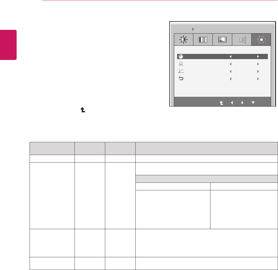
Menu Analog
(D-SUB)
PCoIP Description
LANGUAGE ● ● Setsthemenuscreentothedesiredlanguage.
PCoIP
● x
AllowsthePCoIPtobeturnedONorOFF.
IftheinputisPCoIP,the"PCoIP"optionisdisabled.
ThisoptionisenabledwhenanalogsignalsareinputviaD-SUB.
IfPCoIPisON IfPCoIPisOFF
-UsetheINPUTbuttontoswitch
betweenPCoIPandD-SUB.
-IftheD-SUBcableisremoved,
theinputwillautomaticallybe
switchedtoPCoIP.
-IftheD-SUBcableisre-
moved,"NoSignal"willbe
displayed.
-IfINPUTissettoD-SUB,
whenDCisswitchedfrom
ONtoOFF,PCoIPwillnotbe
enabled.
WHITE BALANCE
●x
Ifthevideocardoutputisdifferentfromthespecifiedlevel,thecolor
mayappeartohavealteredduetothevideosignaldistortion.The
whitebalanceadjuststheoutputsignalleveltocorrespondtothatof
thestandardsignal,thusprovidingoptimaldisplay.Runthisoption
whenthescreendisplaysanimagewithbothwhiteandblack.
FACTORY RESET ● ● Resetsthescreentothefactorydefaultsettings.Notethatthelan-
guageoptionwillnotbereset.
Analog: D-SUB (analog signal) input. PCoIP: Internal signal through the LAN.
Others
1 Pressanybuttononthefrontofthemonitortodis-
playtheMONITOR SETUPOSDmenu.
2 PresstheMENU buttontodisplaytheoptionsinthe
OSDmenu.
3 Settheoptionsbypressingthebuttonsonthefront
ofthemonitor.
4 SelectEXITtoleavetheOSDmenu.
Toreturntotheuppermenuorsetothermenuitems,
usetheuparrow( )button.
Eachoptionisexplainedbelow.
LANGUAGE
EXIT
English
PCoIP ON
NO
NO
WHITE BALANCE
FACTORY RESET
MENU OTHERS