LG Electronics USA N2311AZ Part15 Subpart B-LCD Monitor User Manual BEJN2311AZ 1
LG Electronics USA Part15 Subpart B-LCD Monitor BEJN2311AZ 1
Contents
- 1. BEJN2311AZ_User Manual 1
- 2. BEJN2311AZ_User Manual 2
- 3. BEJN2311AZ_User Manual 3
BEJN2311AZ_User Manual 1

www.lg.com
OWNER'S MANUAL
NETWORK MONITOR
N2311AZ
Please read the safety information carefully before using the product.
Network Monitor Model
English

2
ENG
English
Table of Contents
TABLE OF CONTENTS
3 ASSEMBLING AND
PREPARING
3 Unpacking
4 Partsandbuttons
6 LiftingandmovingtheMonitor
6 SettingUptheMonitorset
6 - AttachingtheStandBase
7 - Mountingonatable
7 - Adjustingtheangle
8 - Adjustingthestandheight
8 - UsingtheKensingtonlockingdevice
9 - Detachingthestandbase
9 - Detachingthestandbody
10 - Swivelstand
10 - UsingthePivotfunction
11 - Installingthewallmountplate
11 - Mountingonawall
13 USING THE MONITOR SET
13 ConnectingInputSignalCable
13 - D-SUBINconnection-PC
13 - D-SUBOUTconnection-PCoIP
14 - DVIconnection-PCoIP
15 ConnectingLAN/Peripherals
15 - LANconnection-PCoIP
16 - Peripheraldeviceconnection
17 - SelfImageAdjustment
18 CUSTOMIZING SETTINGS
18 AccessingTheMainMenus
19 MENUSettings
19 - Picture
20 - Color
21 - Display
21 - Volume(OnlysupportedinPCoIP)
22 - Others
23 AUTOSettings:D-SUBInput
23 -//-Settings:PCoIPInput
24 TROUBLESHOOTING
26 PRODUCT SPECIFICATION
27 PresetMode
27 PowerIndicator
28 PROPER POSTURE
28 Properpostureforusingthemonitor
29 USING PCOIP SOLUTION
3
ENG
English
ASSEMBLING AND PREPARING
ASSEMBLING AND PREPARING
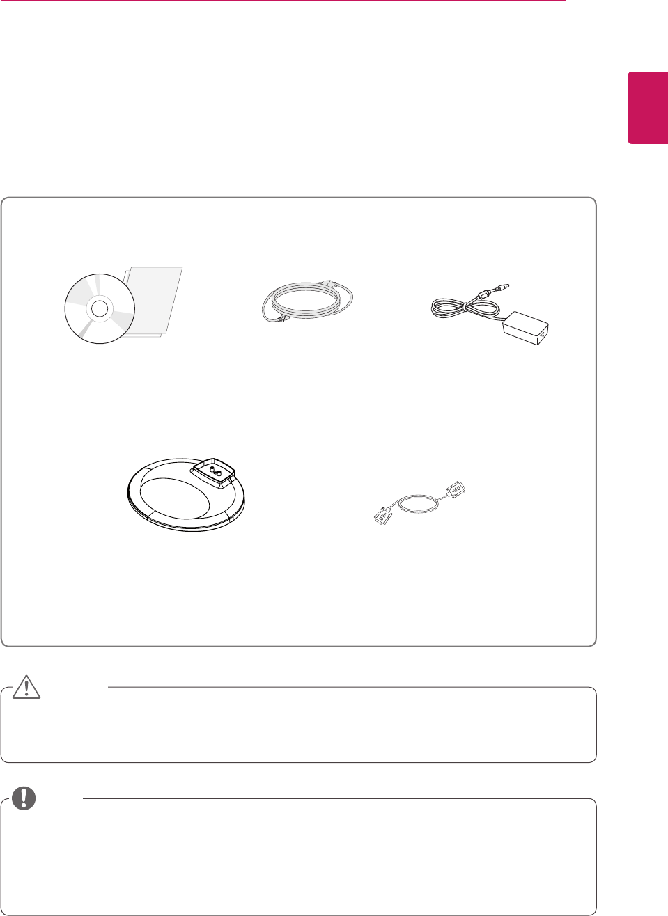
Unpacking
Pleasecheckwhetherallthecomponentsareincludedintheboxbeforeusingtheproduct.Ifthereare
missingcomponents,contacttheretailstorewhereyoupurchasedtheproduct.Notethattheproductand
componentsmaylookdifferentfromthoseshownhere.
OnlyuseanapprovedLGpoweradapter.
Damagecausedbyotherpoweradaptersisnotcoveredbywarranty.
Notethatthecomponentsmaylookdifferentfromthoseshownhere.
Withoutpriornotice,allinformationandspecificationsinthismanualaresubjecttochangetoimprove
theperformanceoftheproduct.
Topurchaseoptionalaccessories,visitanelectronicsstoreoronlineshoppingsiteorcontactthe
retailstorewhereyoupurchasedtheproduct.
Power CordUser Manual/Card
Stand Base
Adaptor
CAUTION
NOTE
15-pin D-SUB Signal Cable
4
ENG
English
ASSEMBLING AND PREPARING
Parts and buttons
Power Indicator
LEDOn:Powerison
LEDOff:Powerisoff
FrontSideButtons
InputConnectors(Seep.13to16)
(PowerButton)
InputConnectors
(Seep.16)

5
ENG
English
ASSEMBLING AND PREPARING
Button Description
MENU Activatesthemainmenu.
OSD Lock/Unlock
Functions
Locks/unlockstheOSDscreen.
TolocktheOSDscreen,pressandholdtheMENUbutton
forseveralseconds.The"OSDLOCKED"messagewillbe
displayedandthescreenwillbelocked.
TounlocktheOSDscreen,pressandholdtheMENU
buttonagainforseveralseconds.The"OSDUNLOCKED"
messagewillbedisplayedandthescreenwillbeunlocked.
VOLUME(OnlyPCoIPmode)
AdjustthevolumeoftheMonitorset.(Seep.21)
AUTO Toadjustthemonitorsettings,presstheAUTObuttonontheMONITORSETUPOSD
menu(onlysupportedforanalogsignal).
Foroptimalscreendisplay,usethefollowingresolution.
Optimal Resolution 1920x1080
INPUT Allowsselectionoftheinputsignal.
IfyouconnectthemonitortoacomputerusingaD-SUBcable,selecteitherthePCoIP
orD-SUBinputsignal.
TheinitialinputsignalisD-SUB.
EXIT ExitstheOSDmenu.
(PowerButton)
D-SUBInput:PowerOn/Off
PCoIPInput
MonitorOff:Pressthepowerbuttononcethenthemonitorwillbeturnedoffafter5
seconds.
PCoIPOff:PressthepowerbuttontwicethenthemonitorandPColPconnectionwill
bedisabled.
PCoIPOn:Pressthepowerbutton.
RemotePCPowerControl:Pressthepowerbuttonforatleastfivesecondstoturn
thePCon/off.
*RemotePCPowerControlonlyworksonthehostPCwherePCoIPhostcardis
installedandrequiresseparatesetup.
Power Indicator Whenthemonitorisinoperatingmode,thepowerindicator
willturnRed(onmode).
Whenthemonitorisinpowersavingmode,thepowerindica-
torwillblinkRed.
6
ENG
English
ASSEMBLING AND PREPARING
Setting Up the Monitor set
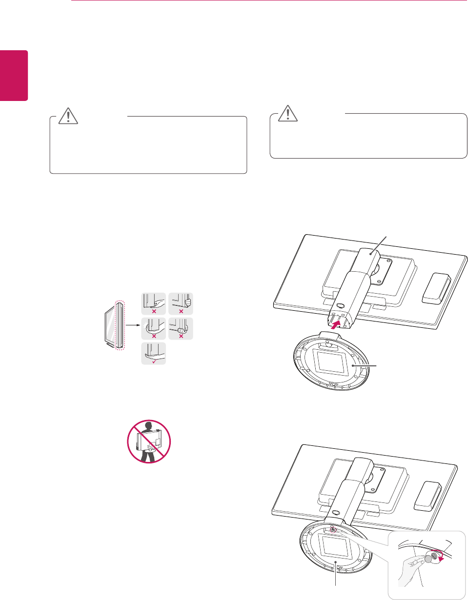
Attaching the Stand Base
1 Placethemonitor'sscreenfacedown.
Toprotectthescreenfromscratches,
coverthesurfacewithasoftcloth.
3 Usingacoin,turnthescrewclockwisetose-
cure the stand base.
2 Checktheposition (at the front and rear) of
thestandbody, then mountthestand baseon
thestand body asshowninthefigure.
Stand Body
Stand Base
CAUTION
Lifting and moving the
Monitor
Pleaseheedthefollowinginformationwhen
movingthemonitor.
Avoidtouchingthescreenatalltimes,asthis
mayresultindamagetothescreenorpixels.
CAUTION
ItisrecommendedtomovetheMonitorin
theboxorpackingmaterialthattheMonitor
originallycamein.
BeforemovingorliftingtheMonitor,
disconnectthepowercordandallcables.
HoldthetopandbottomoftheMonitorframe
firmly.Makesurenottoholdthetransparent
partarea.
WhenholdingtheMonitor,thescreenshould
faceawayfromyoutopreventthescreen
fromscratches.
WhentransportingtheMonitor,donot
exposetheMonitortojoltsorexcessive
vibration.
WhentransportingtheMonitor,keepthe
Monitorupright,neverturntheMonitoronits
side,ortilttowardstheleftorright.
Stand Base
7
ENG
English
ASSEMBLING AND PREPARING
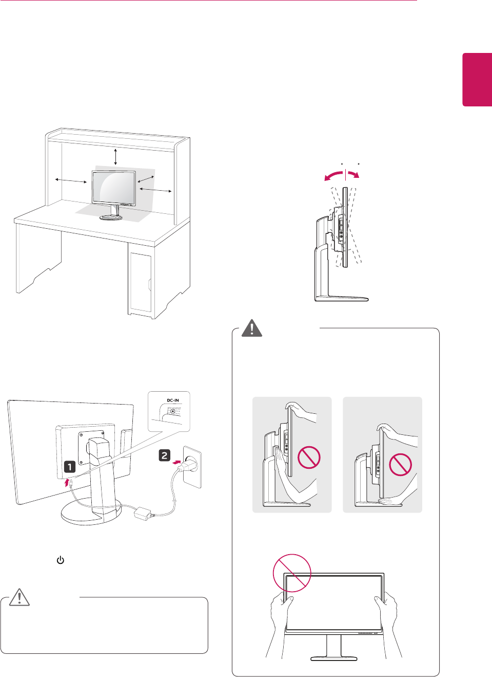
Adjusting the angle
1 Placethemonitormountedonthestandbase
inanuprightposition.
2 Adjusttheangleofthescreen.Theangleof
thescreencanbeadjustedupto5°forwards
and15°backwardsforacomfortableviewing
experience.
Toavoidinjurytothefingerswhenadjusting
thescreen,donotholdasillustratedbelow.
Becarefulnottotouchorpressthescreen
areawhenadjustingtheangleofthemonitor.
Front SideRear Side
WARNING
Mounting on a table
1 Liftthemonitorandplaceitonthetableinan
uprightposition.
Installatleast10 cm awayfromthewallto
ensuresufficientventilation.
2 Connecttheadaptortothemonitor,thenplug
thepowercordintothewalloutlet.
3 Pressthe (Power)buttononthefrontofthe
monitortoturnonthemonitor.
Unplugthepowercordpriortomovingor
installingthemonitor.Thereisriskofelectric
shock.
CAUTION
10 cm
10 cm
10 cm
10 cm -5 15
-5 15
-5 15
8
ENG
English
ASSEMBLING AND PREPARING
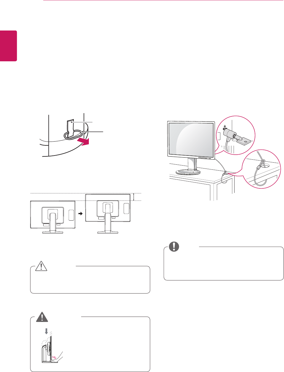
Using the Kensington locking
device
TheconnectorfortheKensingtonlockislocated
ontherearofthemonitor.
Formoreinformationoninstallationandusage,
refertotheKensingtonlockusermanualorvisit
thewebsiteathttp://www.kensington.com.
ConnectthemonitortothetablewiththeKensing-
tonlockcable.
UsingtheKensingtonlockisoptional.The
accessoriescanbepurchasedatyourlocal
electronicsstore.
NOTE
Oncethepinisremoved,itisnotnecessary
tore-insertittoadjusttheheight.
Adjusting the stand height
1 Placethemonitormountedonthestandbase
inanuprightposition.
2 Removethetapeattachedatthebottomrear
ofthe stand body, thenpulloutthelocking
pin.
3 Theheightcanbeadjustedupto110 mm.
Donotputyourfingersor
handbetweenthescreen
andthebase(chassis)when
adjustingthescreen'sheight.
Tape
Locking Pin
Stand Body
CAUTION
WARNING
110.0mm
9
ENG
English
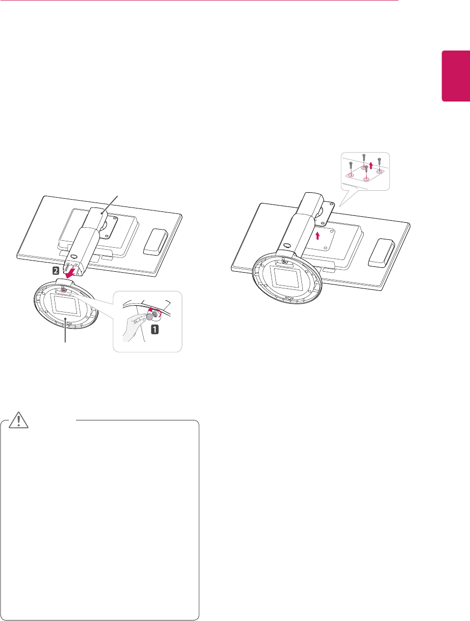
ASSEMBLING AND PREPARING
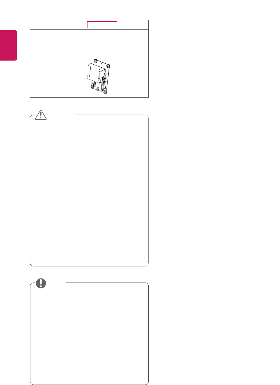
Detaching the stand body
1 Placethemonitor'sscreenfacedown.To
protectthescreenfromscratches,coverthe
surfacewithasoftcloth.
2 Usingascrewdriver,removethefourscrews
anddetachthestandfromthemonitor.
Thecomponentsappearingintheillustra-
tionsmaylookdifferentfromtheactualprod-
uct.
Donotcarrythemonitorupside-downasthis
maycauseittofalloffitsstand,resultingin
damageorinjury.
Toavoiddamagingthescreenwhenlifting
ormovingthemonitor,onlyholdthestandor
theplasticcover.Thisavoidsputtingunnec-
essarypressureonthescreen.
Onlyremovethetapeandthelockingpin
whenthemonitorismountedonthestand
baseandisinanuprightposition.Otherwise,
thestandbodymayprotrude,whichmay
leadtoinjury.
Detaching the stand base
1 Placethemonitor'sscreenfacedown.
Toprotectthescreenfromscratches,coverthe
surfacewithasoftcloth.
2 Usingacoin,turnthescrewinthestandbase
counterclockwise.Detachthestand base from
thestand body.
Stand Body
Stand Base
CAUTION
10
ENG
English
ASSEMBLING AND PREPARING
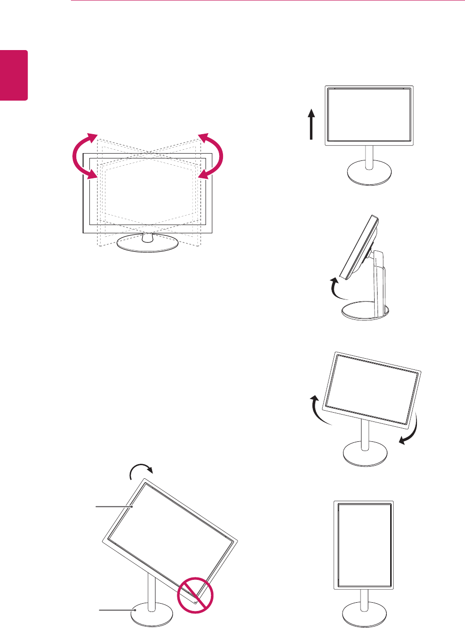
Swivel stand
ImageshownmaydifferfromyourMonitor
set.
1 Swivel356degreesandadjusttheangleofthe
Monitorsettosuityourview.
1 Liftthemonitortoitshighestheighttoutilize
thePivotfunction.
Using the Pivot function
Thepivotfunctionallowsyoutorotatethescreen
90degreesclockwise.
2 Landscape&Portrait:Youcanrotatethepanel
90oclockwise.Pleasebecautiousandavoid
contactbetweenthemonitorheadandthe
StandBasewhenrotatingthescreentoaccess
thePivotfunction.Ifthemonitorheadtouches
theStandBase,thentheStandBasecould
crack.
Head
section
Stand
section
3 Becarefulwiththecableswhenrotatingthe
screen.
11
ENG
English
ASSEMBLING AND PREPARING
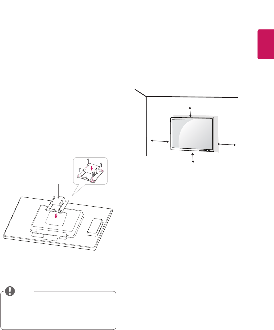
Installing the wall mount plate
ThismonitorhasaVESAcompatiblemountonthe
back.MostmountswillrequireanLGmounting
plate.
1 Placethemonitor'sscreenfacedown.To
protectthescreenfromscratches,coverthe
surfacewithasoftcloth.
2 Placethewallmountplateonthemonitorand
alignitwiththescrewholesonthemonitor.
3 Usingascrewdriver,tightenthefourscrewsto
fixtheplateontothemonitor.
Thewallmountplateissoldseparately.
Formoreinformationontheinstallation,refer
tothewallmountplate'sinstallationguide.
Wall Mount Plate
NOTE
IfyouintendtomounttheMonitorsettoawall,
attachWallmountinginterface(optionalparts)to
thebackoftheset.
WhenyouinstalltheMonitorsetusingawall
mountinginterface(optionalparts),attachit
carefullysoitwillnotdrop.
1Please,Usethescrewandwallmountinterface
inaccordancewithVESAStandards.
2Ifyouusescrewlongerthanstandard,the
monitormightbedamagedinternally.
3Ifyouuseimproperscrew,theproductmightbe
damagedanddropfrommountedposition.In
thiscase,LGElectronicsisnotresponsiblefor
it.
4VESAcompatible.
5PleaseuseVESAstandardasbelow.
784.8mm(30.9inch)andunder
*WallMountPadThickness:2.6mm
*Screw:Φ4.0mmxPitch0.7mmx
Length10mm
787.4mm(31.0inch)andabove
*PleaseuseVESAstandardwallmountpad
andscrews.
Mounting on a wall
Installthemonitoratleast10cmawayfromthe
wallandleaveabout10cmofspaceateachside
ofthemonitortoensuresufficientventilation.De-
tailedinstallationinstructionscanbeobtainedfrom
yourlocalretailstore.Pleaserefertothemanual
toinstallandsetupatiltingwallmountingbracket.
10 cm
10 cm
10 cm
10 cm
12
ENG
English
ASSEMBLING AND PREPARING
Unplugthepowercordbeforemovingorin-
stallingthemonitortoavoidelectricshocks.
Installingthemonitorontheceilingorona
slantedwallmayresultinthemonitorfalling
off,whichcouldleadtoinjury.Pleaseuse
aLGwallmountingbracketwhenusinga
VESAmount.Formoreinformation,contact
yourlocalretailstoreoraqualifiedinstaller.
Applyingexcessiveforcewhenfastening
screwsmaycausedamagetothemoni-
tor.Damagecausedinthiswaywillnotbe
coveredbytheproductwarranty.
Usethewallmountingbracketandscrews
thatconformtotheVESAstandard.Dam-
agecausedbytheuseormisuseofinap-
propriatecomponentswillnotbecovered
bytheproductwarranty.
UsethescrewsspecifiedintheVESAstan-
dard.
Thewallmountkitincludestheinstallation
guideandnecessaryparts.
Thewallmountingbracketisoptional.The
accessoriescanbepurchasedatyourlocal
retailstore.
Thelengthofthescrewmaydifferforeach
wallmountingbracket.Ensurethecorrect
lengthofthescrewisused.
Formoreinformation,pleaserefertotheuser
manualforthewallmountingbracket.
Model N2311AZ
VESA (A x B) 100x100
Stand Screw M4
Required Screw 4
Wall Mount Plate
(Optional)
RW120
CAUTION
NOTE
13
ENG
English
USING THE MONITOR SET
USING THE MONITOR SET
Connecting Input Signal Cable
Thismonitorsupportsthe*PlugandPlay
feature.
*PlugandPlay:Afeaturethatallowsyouto
addadevicetoyourcomputer,withouthaving
toreconfigureanythingorinstallanymanual
drivers.
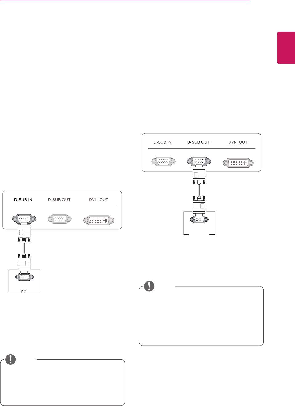
D-SUB IN connection - PC
D-SUBINtransfersanalogvideosignalsfromthe
PCtothemonitor.
ConnectthemonitortothePCusingtheprovided
15-pinD-SUBsignalcableasillustratedbelow.
Apple Adapter
AnadaptermaybeneededforApple
computers.Thisadaptercanbepurchased
fromApple.
Whenusingthisdevicesimplyasaregu-
larmonitorthroughtheRGBINport,set
"PCoIP"toOFFinMENU>OTHERSto
reduceenergyconsumption.(Seep.22)
NOTE
NOTE
RGB OUT
RGB IN
MONITOR
RGB OUT
RGB IN
MONITOR
D-SUB OUT connection - PCoIP
D-SUBOUTcanonlymirrorthePCoIPimage
displayedonthemonitor.(itdoesnotsupportan
extendeddesktop).
ConnectthemonitortothePCusingtheprovided
15-pinD-SUBsignalcableasillustratedbelow.
14
ENG
English
USING THE MONITOR SET
Toconnectthemonitortoacomputer,use
theappropriatesignalcable(LANandD-
SUB).
AconvertercanbeusedtoconverttheDVI-I
inputsignaltoD-SUBinputsignal.
Whenconnectingthepowercordtotheout-
let,useagrounded(3-hole)multi-socketora
groundedwalloutlet.
Themonitormayflickerwhenturnedoninan
areaoflowtemperature.Thisisnormal.
Sometimesred,greenorbluespotsmayap-
pearonthescreen.Thisisnormal.
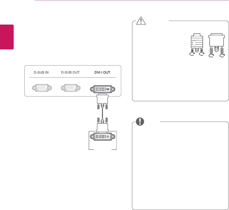
Connecttheinputsignal
cableandtighteninthe
directionofthearrow.To
preventdisconnection
securethecabletightly.
Donotpressonthescreenforaprolonged
time.Thismaycauseimagedistortion.
Donotdisplayastillimageonthescreen
foraprolongedtime.Thismaycauseimage
retention.Ifpossible,usethescreensaver.
DVI-I(D) IN
MONITOR
CAUTION
NOTE
DVI connection - PCoIP
Transfersvideosignalstoanothermonitor.Con-
nectthemonitorusingtheDVIcableasillustrated
below.
ItisusedfortheexpansionorreplicationofPCoIP
modescreen.
15
ENG
English
USING THE MONITOR SET
Connecting LAN/Peripherals
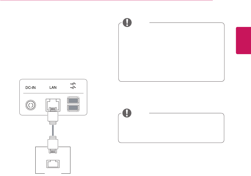
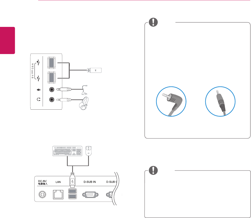
LAN connection - PCoIP
TheLANconnectiontransmitsPCoIPsignalsto
themonitor.Connecttherouterorswitchtothe
monitorusingaLANcableasillustratedbelow.
TheLANcableissoldseparately.
ThefollowingLANcabletypecanbeused:
Standard:IEEE802.3ETHERNET
Ifadeviceisconnectedintotheearphone
outportviaaLANcable,youcanadjustthe
volumewiththevolumeicononPCtaskbar.
ConnecttheLANcableandtheperipheral
devicespriortobootingupthePC.
LAN
Hub/Router
NOTE
NOTE
16
ENG
English
USING THE MONITOR SET
Peripheraldevicesaresoldseparately.
TheUSBportsontheleftandbottomofthe
monitorcanbeusedtoconnectthekey-
board,mouse,andotherUSBdevices.
Cableswithangledplugsmayhaveclear-
anceissues,usestraightplugswhenpos-
sible.
AngleType StraightType
Peripheral device connection
Connectperipheraldevicestothemonitorusing
USB,microphoneandheadphoneports.
Left
Bottom
NOTE
NOTE
Headphones,speakersormicrophonemay
notworknormally,dependingontheserver
PCsettings.
Virtualsolutionsmayaffectthefunctionsor
speedofthespecificUSBstoragedevice.
17
ENG
English
USING THE MONITOR SET
Whatis"SelfImageAdjustment"?Thisfunc-
tionrunswhenthemonitorisconnectedfor
thefirsttimeandperformsautomaticimage
adjustmentforeachsignal(onlyavailablefor
analog[D-SUBinput]signals)toprovidean
optimalscreendisplay.
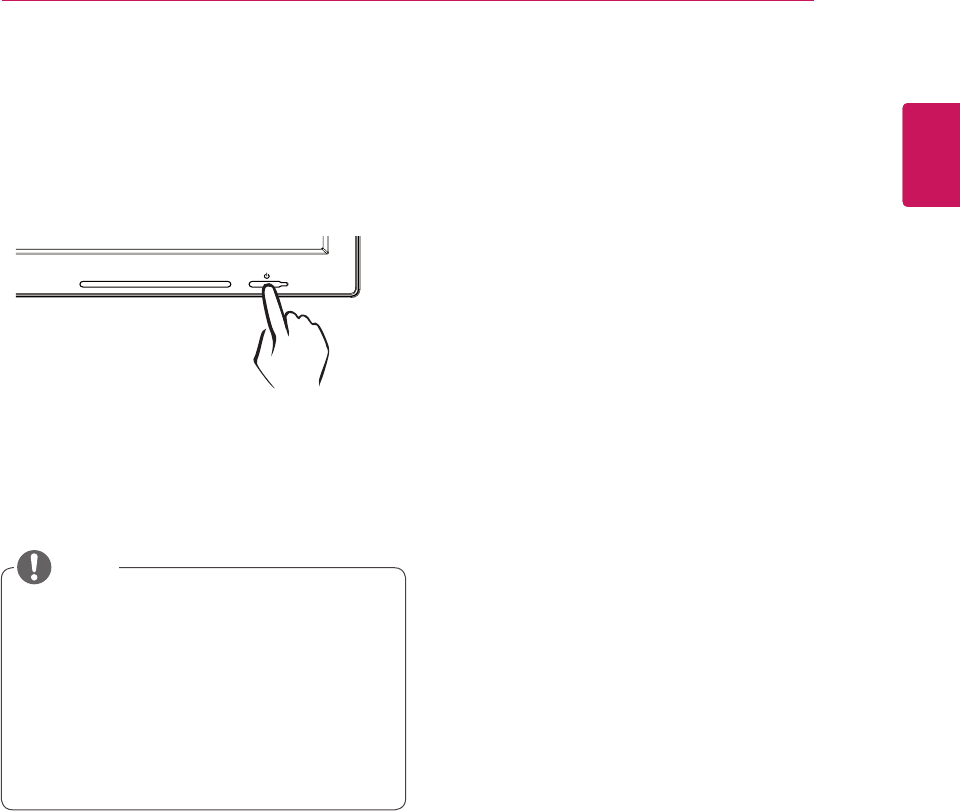
Self Image Adjustment
Pressthepowerbuttononthefronttoturnon
themonitor.Whenpoweredon,the"Self Image
Adjustment" functionwillrunautomatically(only
availableforanalog[D-SUBinput]signals).
NOTE
18
ENG
English
CUSTOMIZING SETTINGS
CUSTOMIZING SETTINGS
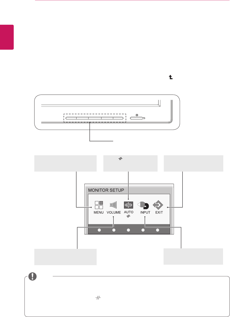
Accessing The Main Menus
1 PressanybuttononthefrontofthemonitortodisplaytheMONITORSETUPOSDmenu.
2 Presstoselectthedesiredmenuitem.
3 Tochangethesettingsoftheselecteditempressthebuttonsonthefrontofthemonitor.
Toreturntotheuppermenuorsetothermenuitems,usetheuparrow( )button.
4 SelectEXITtoleavetheOSDmenu.
MENU (See p.19)
Setsthescreenoptions.
EXIT(See p.5)
ExitstheOSDmenu.
AUTO /
(Seep.23)
Optimizestheresolution.
/Disconnectsfromtheserver.
Differentmenuitemsareenableddependingonthetypeofinputsignal.
D-SUB Input: MENU,AUTO,INPUT,EXIT
PCoIP Input: MENU,VOLUME, ,INPUT,EXIT
Thelanguageofthemonitor'sOSDmenuandthatoftheOSDmenuillustratedintheCD-ROM
manualmaybedifferent.
VOLUME (See p.21)
Setsthevolume.
INPUT (See p.5)
Setstheexternalinput.
NOTE
Front Side Buttons
19
ENG
English
CUSTOMIZING SETTINGS
MENU Settings
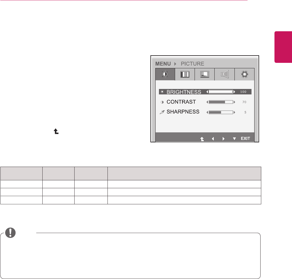
Picture
1 Pressanybuttononthefrontofthemonitortodis-
playtheMONITOR SETUP OSDmenu.
2 PresstheMENU buttontodisplaytheoptionsinthe
OSDmenu.
3 Settheoptionsbypressingthebuttonsonthefront
ofthemonitor.
4 SelectEXITtoleavetheOSDmenu.
Toreturntotheuppermenuorsetothermenuitems,
usetheuparrow( )button.
Eachoptionisexplainedbelow.
Menu Analog
(D-SUB)
PCoIP Description
BRIGHTNESS o o Setsthebrightnessofthescreen.
CONTRAST o o Setsthecontrastofthescreen.
SHARPNESS o o Setsthesharpnessofthescreen.
Ifthescreenisnotdisplayedproperlyafteradjustingthesettings,usethe"FACTORYRESET"
optiontorevertbacktothefactorydefaultsettings.Ifnecessary,enablethe"WHITEBALANCE"
optionagain.Thisoptionisenabledonlyforanalog(D-SUB)signals.
Analog: D-SUB (analog signal) input. PCoIP: Internal signal through the LAN.
NOTE
20
ENG
English
CUSTOMIZING SETTINGS
Menu Analog
(D-SUB)
PCoIP Description
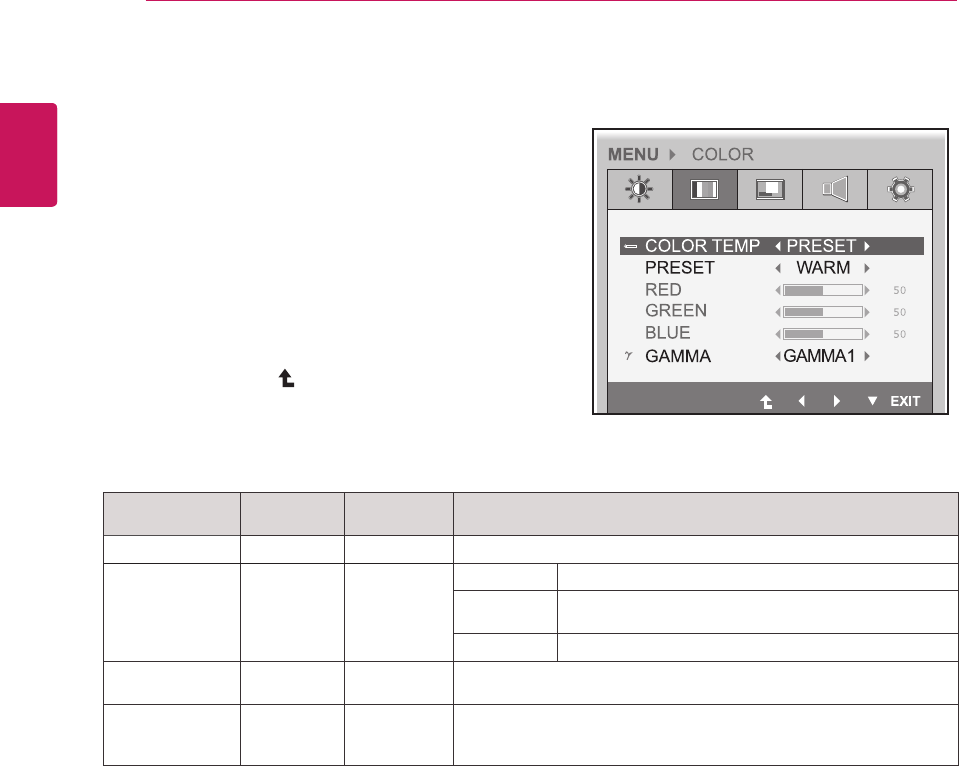
COLOR TEMP o o AllowsPRESETorUSERtobeselected.
WARM Setsthescreencolortoareddishtone.
MEDIUM Setsthescreencolorbetweenthereddishandbluish
tone.
COOL Setsthescreencolortoabluishtone.
USER o o YoucancustomizethepicturecolorusingRed,Green,andBlue
colors.
GAMMA
o o
Setstheclarityofthescreen.
Thegammavaluecanbesetto0,1or2,fromdarkertobrighter
screencolorsrespectively.
Analog: D-SUB (analog signal) input. PCoIP: Internal signal through the LAN.
Color
1 Pressanybuttononthefrontofthemonitortodis-
playtheMONITOR SETUP OSDmenu.
2 PresstheMENU buttontodisplaytheoptionsinthe
OSDmenu.
3 Settheoptionsbypressingthebuttonsonthefront
ofthemonitor.
4 SelectEXIT toleavetheOSDmenu.
Toreturntotheuppermenuorsetothermenuitems,
usetheuparrow( )button.
Eachoptionisexplainedbelow.
21
ENG
English
CUSTOMIZING SETTINGS
Menu Analog
(D-SUB)
PCoIP Description
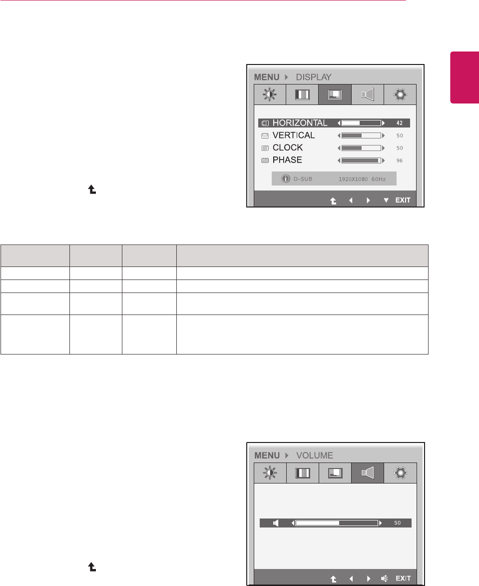
HORIZONTAL oxMovesthedisplayarealeftorright.
VERTICAL oxMovesthedisplayareaupordown.
CLOCK oxIfverticallinesareshownonthescreen,adjustthefrequencytomini-
mizethelinesandadjustthescreen'shorizontalwidth.
PHASE
ox
Adjuststhefocusofthescreen'simage.
Usewhenfrequenciesareshownonthescreenorwhenthetextap-
pearsoverlapped.Foroptimalresults,usethisoptionafteradjusting
the"CLOCK"option.
Analog: D-SUB (analog signal) input. PCoIP: Internal signal through the LAN.
Display
1 Pressanybuttononthefrontofthemonitortodis-
playtheMONITOR SETUP OSDmenu.
2 PresstheMENU buttontodisplaytheoptionsinthe
OSDmenu.
3 Settheoptionsbypressingthebuttonsonthefront
ofthemonitor.
4 SelectEXITtoleavetheOSDmenu.
Toreturntotheuppermenuorsetothermenuitems,
usetheuparrow( )button.
Eachoptionisexplainedbelow.
Volume (Only supported in PCoIP)
1 Pressanybuttononthefrontofthemonitortodis-
playtheMONITOR SETUP OSDmenu.
2 PresstheMENU buttontodisplaytheoptionsinthe
OSDmenu.
3 Settheoptionsbypressingthebuttonsonthefront
ofthemonitor.
4 SelectEXITtoleavetheOSDmenu.
Toreturntotheuppermenuorsetothermenuitems,
usetheuparrow( )button.