LG Electronics USA NS42PDP09 PLASMA TV/MONITOR User Manual NS 42PDP 09 manual
LG Electronics USA PLASMA TV/MONITOR NS 42PDP 09 manual
Contents
- 1. User manual 1 of 2
- 2. User manual 2of 2
User manual 1 of 2

Please read this manual carefully before operating
your set.
Retain it for future reference.
Record model number and serial number of the set.
See the label attached on the back cover and quote
this information to your dealer
when you require service.
PLASMA TV
OWNER’S MANUAL
42PG10 50PG10
42PG20 50PG20
42PG20C 50PG20C
50PG30 60PG30
NS-42PDP-09
NS-50PDP-09
P/NO : SAC30708031 (0801-REV00)
www.lgusa.com / www.lg.ca / www.lgcommercial.com
As an ENERGY STAR
Partner LGE U. S. A.,Inc.
has determined that this
product meets the
ENERGY STAR guidelines
for energy efficiency.
ENERGY STAR is a set of power-saving
guidelines issued by the U.S.
Environmental Protection Agency(EPA).

1
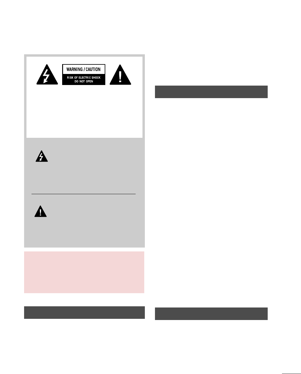
WARNING / CAUTION
WARNING / CAUTION
To prevent fire or shock hazards, do not expose
this product to rain or moisture.
FCC NOTICE
Class B digital device
This equipment has been tested and found to comply
with the limits for a Class B digital device, pursuant to
Part 15 of the FCC Rules. These limits are designed
to provide reasonable protection against harmful
interference in a residential installation. This equipment
generates, uses and can radiate radio frequency energy
and, if not installed and used in accordance with the
instructions, may cause harmful interference to radio
communications. However, there is no guarantee that
interference will not occur in a particular installation.
If this equipment does cause harmful interference to
radio or television reception, which can be determined
by turning the equipment off and on, the user is
encouraged to try to correct the interference by one
or more of the following measures:
- Reorient or relocate the receiving antenna.
- Increase the separation between the equipment and
receiver.
- Connect the equipment to an outlet on a circuit
different from that to which the receiver is connected.
- Consult the dealer or an experienced radio/TV
technician for help.
Any changes or modifications not expressly approved
by the party responsible for compliance could void
the user’s authority to operate the equipment.
CAUTION
Do not attempt to modify this product in any way
without written authorization from LG Electronics.
Unauthorized modification could void the user’s
authority to operate this product
The lightning flash with arrowhead
symbol, within an equilateral triangle, is
intended to alert the user to the presence
of uninsulated “dangerous voltage” within the
product’s enclosure that may be of sufficient
magnitude to constitute a risk of electric shock to
persons.
The exclamation point within an equilateral
triangle is intended to alert the user to
the presence of important operating and
maintenance (servicing) instructions in the litera-
ture accompanying the appliance.
TO REDUCE THE RISK OF ELECTRIC SHOCK
DO NOT REMOVE COVER (OR BACK). NO
USER SERVICEABLE PARTS INSIDE. REFER TO
QUALIFIED SERVICE PERSONNEL.
WARNING/CAUTION
TO REDUCE THE RISK OF FIRE AND ELECTRIC
SHOCK, DO NOT EXPOSE THIS PRODUCT TO
RAIN OR MOISTURE.
NOTE TO CABLE/TV INSTALLER
This reminder is provided to call the CATV system
installer’s attention to Article 820-40 of the National
Electric Code (U.S.A.). The code provides guidelines for
proper grounding and, in particular, specifies that the
cable ground shall be connected to the grounding system
of the building, as close to the point of the cable entry
as practical.
2
IMPORTANT SAFETY INSTRUCTIONS
SAFETY INSTRUCTIONS
Important safety instructions shall be provided with each apparatus. This information shall be given in a separate
booklet or sheet, or be located before any operating instructions in an instruction for installation for use and
supplied with the apparatus.
This information shall be given in a language acceptable to the country where the apparatus is intended to be used.
The important safety instructions shall be entitled “Important Safety Instructions”. The following safety
instructions shall be included where applicable, and, when used, shall be verbatim as follows. Additional safety
information may be included by adding statements after the end of the following safety instruction list. At the
manufacturer’s option, a picture or drawing that illustrates the intent of a specific safety instruction may be
placed immediately adjacent to that safety instruction:
Read these instructions.
Keep these instructions.
Heed all warnings.
Follow all instructions.
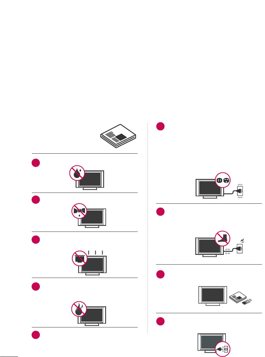
Do not use this apparatus near water.
Clean only with dry cloth.
Do not block any ventilation openings. Install in
accordance with the manufacturer’s instructions.
Do not install near any heat sources such as
radiators, heat registers, stoves, or other apparatus
(including amplifiers)that produce heat.
When mounting a TV it on the wall, make sure
not to install TV by the hanging power and sig-
nal cables on the back of the TV.
Do not defeat the safety purpose of the polarized
or grounding-type plug. A polarized plug has
two blades with one wider than the other. A
grounding type plug has two blades and a third
grounding prong, The wide blade or the third
prong are provided for your safety. If the provided
plug does not fit into your outlet, consult an
electrician for replacement of the obsolete outlet.
Protect the power cord from being walked on
or pinched particularly at plugs, convenience
receptacles, and the point where they exit from
the apparatus.
Only use attachments/accessories specified by
the manufacturer.
Unplug this apparatus when unused for long
periods of time.
1
2
3
4
5
6
7
8
9
3
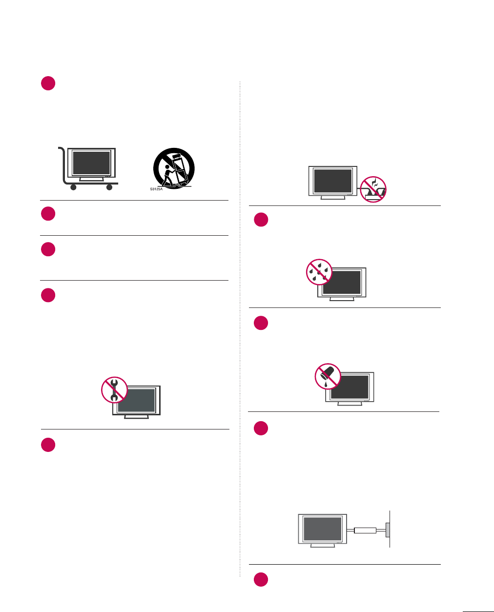
Use only with the cart, stand, tripod, bracket,
or table specified by the manufacturer, or sold
with the apparatus. When a cart is used, use
caution when moving the cart/apparatus
combination to avoid injury from tip-over.
Never touch this apparatus or antenna during
a thunder or lighting storm.
Do not allow a impact shock or any objects to
fall into the product, and do not drop onto the
screen with something.
Refer all servicing to qualified service personnel.
Servicing is required when the apparatus has
been damaged in any way, such as power-supply
cord or plug is damaged, liquid has been
spilled or objects have fallen into the apparatus,
the apparatus has exposed to rain or moisture,
does not operate normally, or has been
dropped.
CAUTION concerning the Power Cord :
Most appliances recommend they be placed
upon a dedicated circuit; that is, a single outlet
circuit which powers only that appliance and
has no additional outlets or branch circuits.
Check the specification page of this owner's
manual to be certain.
Do not overload wall outlets. Overloaded wall
outlets, loose or damaged wall outlets, extension
cords, frayed power cords, or damaged or
cracked wire insulation are dangerous. Any of
these conditions could result in electric shock
or fire. Periodically examine the cord of your
appliance, and if its appearance indicates dam-
age or deterioration, unplug it, discontinue use
of the appliance, and have the cord replaced
with an exact replacement part by an authorized
servicer. Protect the power cord from physical
or mechanical abuse, such as being twisted,
kinked, pinched, closed in a door, or walked
upon. Pay particular attention to plugs, wall
outlets, and the point where the cord exits the
appliance.
Outdoor use marking :
WARNING - To reduce the risk of fire or elec-
tric shock, do not expose this appliance to rain
or moisture.
Wet Location Marking : Apparatus shall not be
exposed to dripping or splashing and no
objects filled with liquids, such as vases, shall
be placed on or over apparatus.
GROUNDING
Ensure that you connect the earth ground wire
to prevent possible electric shock. If grounding
methods are not possible, have a qualified
electrician install a separate circuit breaker.
Do not try to ground the unit by connecting it
to telephone wires, lightening rods, or gas pipes.
DISCONNECTING DDEVICE FFROM MMAINS
Mains plug is the disconnecting device. The
plug must remain readily operable.
12
10
11
14
13
15
16
17
18
Power
Supply
Short-circuit
Breaker

4
CONTENTS
WARNING / CAUTION
. . . . . . . . . . . . . . . . . . . . . . . . . . . . 1
SAFETY INSTRUCTIONS
. . . . . . . . . . . . . . . . . . . . . . . . . . 2
FEATURE OF THIS TV
. . . . . . . . . . . . . . . . . . . . . . . . . . . . . . . 6
PREPARATION
Accessories . . . . . . . . . . . . . . . . . . . . . . . . . . . . . . . . . . . . . . . . . . . . . . . . . . . . . . 7
Front Panel Information . . . . . . . . . . . . . . . . . . . . . . . . . . . . . . . . . . . . . 8
Back Panel Information . . . . . . . . . . . . . . . . . . . . . . . . . . . . . . . . . . . . . . 9
Stand Installation . . . . . . . . . . . . . . . . . . . . . . . . . . . . . . . . . . . . . . . . . . . . 10
Cable Management . . . . . . . . . . . . . . . . . . . . . . . . . . . . . . . . . . . . . . . . . . 11
Desktop Pedestal Installation . . . . . . . . . . . . . . . . . . . . . . . . . . . . 12
Swivel Stand . . . . . . . . . . . . . . . . . . . . . . . . . . . . . . . . . . . . . . . . . . . . . . . . . . . . 12
VESA Wall Mounting . . . . . . . . . . . . . . . . . . . . . . . . . . . . . . . . . . . . . . . . 13
Protection Cover . . . . . . . . . . . . . . . . . . . . . . . . . . . . . . . . . . . . . . . . . . . . . 13
Securing the TV to the wall to prevent falling . . . . 14
Antenna or Cable Connection . . . . . . . . . . . . . . . . . . . . . . . . . . 15
EXTERNAL EQUIPMENT SETUP
HD Receiver Setup . . . . . . . . . . . . . . . . . . . . . . . . . . . . . . . . . . . . . . . . . 16
DVD Setup . . . . . . . . . . . . . . . . . . . . . . . . . . . . . . . . . . . . . . . . . . . . . . . . . . . . . . 19
VCR Setup . . . . . . . . . . . . . . . . . . . . . . . . . . . . . . . . . . . . . . . . . . . . . . . . . . . . . 21
Other A/V Source Setup . . . . . . . . . . . . . . . . . . . . . . . . . . . . . . . . . 23
Audio Out Connection . . . . . . . . . . . . . . . . . . . . . . . . . . . . . . . . . . . . 23
PC Setup . . . . . . . . . . . . . . . . . . . . . . . . . . . . . . . . . . . . . . . . . . . . . . . . . . . . . . . . 24
WATCHING TV / CHANNEL CONTROL
Remote Control Functions . . . . . . . . . . . . . . . . . . . . . . . . . . . . . . . 30
Turning On TV . . . . . . . . . . . . . . . . . . . . . . . . . . . . . . . . . . . . . . . . . . . . . . . . 32
Channel Selection . . . . . . . . . . . . . . . . . . . . . . . . . . . . . . . . . . . . . . . . . . . 32
Volume Adjustment . . . . . . . . . . . . . . . . . . . . . . . . . . . . . . . . . . . . . . . . . 32
Quick Menu . . . . . . . . . . . . . . . . . . . . . . . . . . . . . . . . . . . . . . . . . . . . . . . . . . . . 33
On-Screen Menus Selection . . . . . . . . . . . . . . . . . . . . . . . . . . . . . 34
Channel Setup
- Auto Scan (Auto Tuning) . . . . . . . . . . . . . . . . . . . . . . . . . . . 35
- Add / Delete Channel (Manual Tuning) . . . . . . 36
- Channel Editing . . . . . . . . . . . . . . . . . . . . . . . . . . . . . . . . . . . . . . . . 37
Input List . . . . . . . . . . . . . . . . . . . . . . . . . . . . . . . . . . . . . . . . . . . . . . . . . . . . . . . . 38
Input Label . . . . . . . . . . . . . . . . . . . . . . . . . . . . . . . . . . . . . . . . . . . . . . . . . . . . . 39
AV Mode . . . . . . . . . . . . . . . . . . . . . . . . . . . . . . . . . . . . . . . . . . . . . . . . . . . . . . . . 40
SIMPLINK . . . . . . . . . . . . . . . . . . . . . . . . . . . . . . . . . . . . . . . . . . . . . . . . . . . . . . . 41
PICTURE CONTROL
Picture Size (Aspect Ratio) Control . . . . . . . . . . . . . . . . . . 44
Preset Picture Settings
- Picture Mode - Preset . . . . . . . . . . . . . . . . . . . . . . . . . . . . . . . 46
- Color Tone - Preset . . . . . . . . . . . . . . . . . . . . . . . . . . . . . . . . . . . 47
Manual Picture Adjustment
- Picture Mode - User Mode . . . . . . . . . . . . . . . . . . . . . . . . 48
- Picture Mode - Expert Control . . . . . . . . . . . . . . . . . . 49
Picture Improvement Technology . . . . . . . . . . . . . . . . . . . . . 50
Advanced Control - Black (Darkness) Level . . . . . . . 51
Advanced Control - Film Mode . . . . . . . . . . . . . . . . . . . . . . . . 52
Picture Reset . . . . . . . . . . . . . . . . . . . . . . . . . . . . . . . . . . . . . . . . . . . . . . . . . 53
Image Sticking Minimization (ISM) Method . . . . . . 54
Power Saving Picture Mode . . . . . . . . . . . . . . . . . . . . . . . . . . . . . . 55

5
SOUND & LANGUAGE CONTROL
Auto Volume Leveler (Auto Volume) . . . . . . . . . . . . . . . . . 56
Clear Voice . . . . . . . . . . . . . . . . . . . . . . . . . . . . . . . . . . . . . . . . . . . . . . . . . . . . . 57
Preset Sound Setting (Sound Mode) . . . . . . . . . . . . . . . . 58
Sound Setting Adjustment - User Mode . . . . . . . . . . . 59
Balance . . . . . . . . . . . . . . . . . . . . . . . . . . . . . . . . . . . . . . . . . . . . . . . . . . . . . . . . . . 60
TV Speakers On/Off Setup . . . . . . . . . . . . . . . . . . . . . . . . . . . . . . 61
Audio Reset . . . . . . . . . . . . . . . . . . . . . . . . . . . . . . . . . . . . . . . . . . . . . . . . . . . 62
Stereo/SAP Broadcasts Setup . . . . . . . . . . . . . . . . . . . . . . . . . . 63
Audio Language . . . . . . . . . . . . . . . . . . . . . . . . . . . . . . . . . . . . . . . . . . . . . . 64
On-Screen Menus Language Selection . . . . . . . . . . . . . 65
Caption Mode
- Analog Broadcasting System Captions . . . . . . . 66
- Digital Broadcasting System Captions . . . . . . . . 67
- Caption Option . . . . . . . . . . . . . . . . . . . . . . . . . . . . . . . . . . . . . . . 68
TIME SETTING
Clock Setting
- Auto Clock Setup . . . . . . . . . . . . . . . . . . . . . . . . . . . . . . . . . . . . 69
- Manual Clock Setup . . . . . . . . . . . . . . . . . . . . . . . . . . . . . . . . . 70
Auto On/Off Time Setting . . . . . . . . . . . . . . . . . . . . . . . . . . . . . . 71
Sleep Timer Setting . . . . . . . . . . . . . . . . . . . . . . . . . . . . . . . . . . . . . . . . . 72
Auto Shut-off Setting . . . . . . . . . . . . . . . . . . . . . . . . . . . . . . . . . . . . . . . 73
PARENTAL CONTROL / RATINGS
Set Password & Lock System . . . . . . . . . . . . . . . . . . . . . . . . . . . 74
Channel Blocking . . . . . . . . . . . . . . . . . . . . . . . . . . . . . . . . . . . . . . . . . . . . 77
Movie & TV Rating . . . . . . . . . . . . . . . . . . . . . . . . . . . . . . . . . . . . . . . . . . 78
Downloadable Rating . . . . . . . . . . . . . . . . . . . . . . . . . . . . . . . . . . . . . . 83
External Input Blocking . . . . . . . . . . . . . . . . . . . . . . . . . . . . . . . . . . . . 84
Key lock . . . . . . . . . . . . . . . . . . . . . . . . . . . . . . . . . . . . . . . . . . . . . . . . . . . . . . . . . 85
APPENDIX
Troubleshooting . . . . . . . . . . . . . . . . . . . . . . . . . . . . . . . . . . . . . . . . . . . . . . 86
Maintenance . . . . . . . . . . . . . . . . . . . . . . . . . . . . . . . . . . . . . . . . . . . . . . . . . . . 88
Product Specifications . . . . . . . . . . . . . . . . . . . . . . . . . . . . . . . . . . . . . 88
IR Codes . . . . . . . . . . . . . . . . . . . . . . . . . . . . . . . . . . . . . . . . . . . . . . . . . . . . . . .90
External Control Through RS-232C . . . . . . . . . . . . . . . . . .92

6
FEATURE OF THIS TV
is a trademark of SRS Labs, Inc.
TruSurround XT technology is incorporated under
license from SRS Labs, Inc.
Manufactured under license from Dolby Laboratories.
“
Dolby
“and the double-D symbol are trademarks of
Dolby Laboratories.
PREPARATION
7
PREPARATION
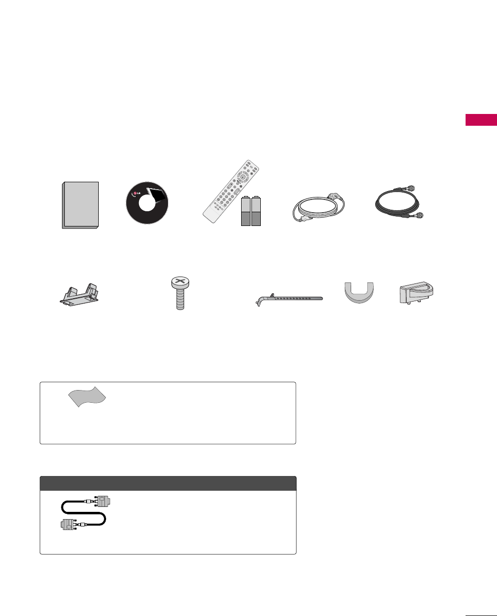
ACCESSORIES
Ensure that the following accessories are included with your TV. If an accessory is missing, please contact the
dealer where you purchased the TV.
The accessories included may differ from the images below.
Option EExtras
Cable Management Clip
Protection Cover
(Refer to P.13)
* Wipe spots on the exterior only with the polishing cloth.
* Do not wipe roughly when removing stain. Please be
cautions of that excessive pressure may cause scratch or
discoloration.
Polishing Cloth
(This feature is not available
for all models.)
Copyright© 2007 LGE,
All Rights Reserved.
D-sub 15 pin Cable
1.5V 1.5V
Owner’s Manual Power Cord 75ohm Round Cable
Remote Control,
Batteries
INPUT
FAV
MUTE
RATIO
SOUND
POWER
Q.MENUMENU
AVMODE
RETURN
ENTER
VOLCH
123
456
78
0
9
FLASHBK
P
A
G
E
SLEEP
PICTURE
CD Manual
(Only 42PG10/20/20C)
Bolts for stand assembly
(Refer to P.10)
x 4 or
When using the VGA (D-sub 15 pin cable)
PC connection, the user must use shielded
signal interface cables with ferrite cores to
maintain standards compliance.
Cable Holder
42PG10/20/20C: 1EA,
50PG10/20/20C: 2EA
PREPARATION
8
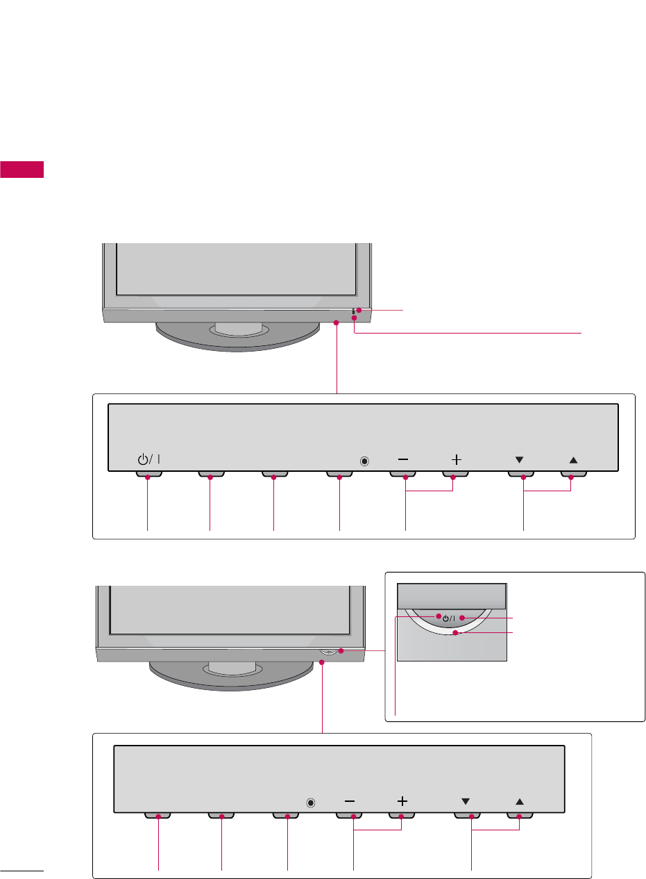
FRONT PANEL INFORMATION
PREPARATION
■
Image shown may differ from your TV.
■
NOTE: If your TV has a protection tape attached, remove the tape.
And then wipe the TV with a cloth (If a polishing cloth is included with your TV, use it).
CH
VOL
MENU
INPUT ENTER
INPUT
Button
MENU
Button
ENTER
Button
VOLUME
(-, +) Buttons
CHANNEL
(E,D)Buttons
Remote Control Sensor
POWER Button
Power/Standby Indicator
Illuminates red in standby mode.
Illuminates blue when the TV is switched on.
CH
VOL
MENU
INPUT ENTER
INPUT
Button
POWER
Button
MENU
Button
ENTER
Button
VOLUME
(-, +) Buttons
CHANNEL
(E,D)Buttons
Remote Control Sensor
Power/Standby Indicator
Illuminates red in standby mode.
Illuminates blue when the TV is switched on.
42/50PG20/20C, 50/60PG30
42/50PG10
PREPARATION
9
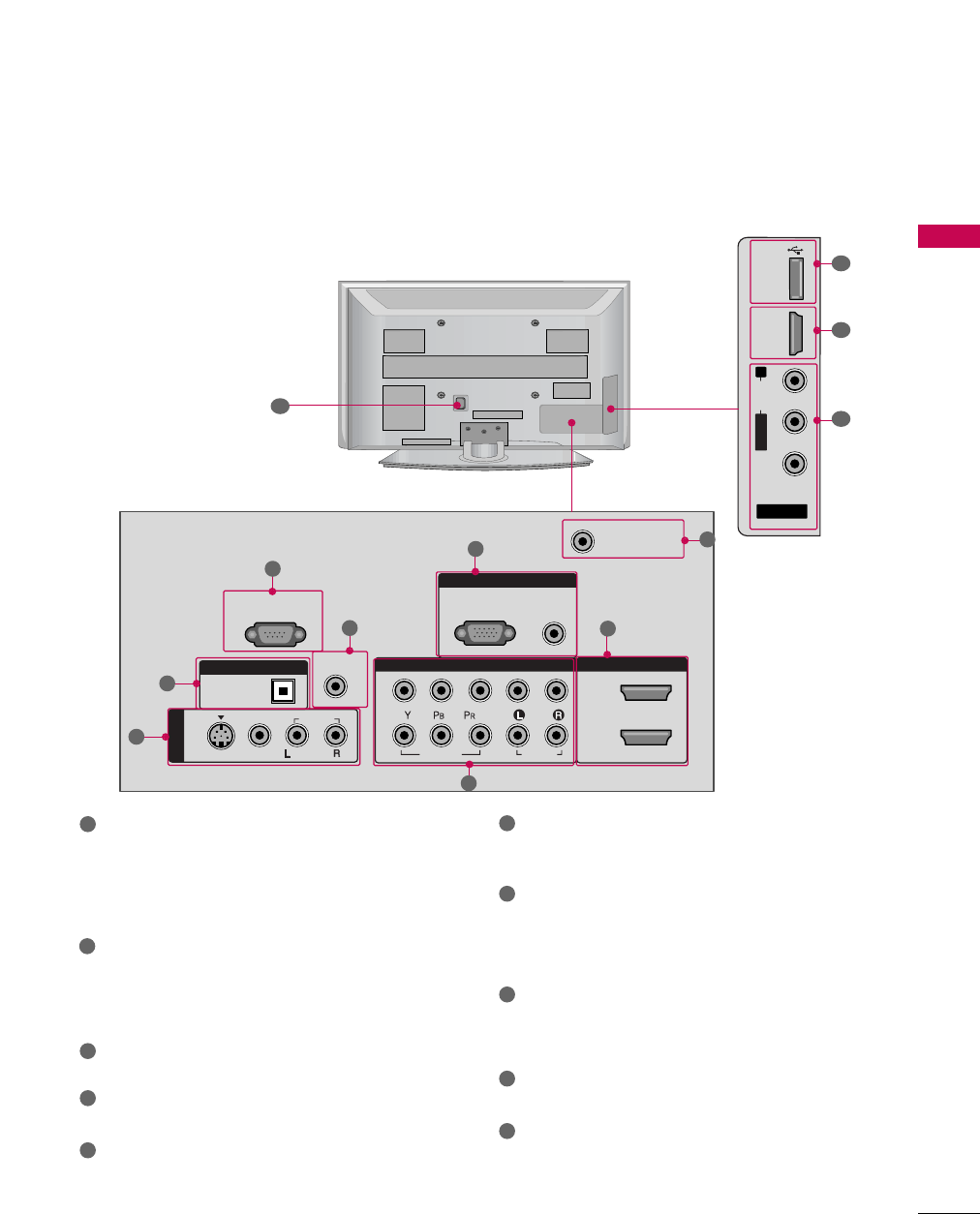
BACK PANEL INFORMATION
■
Image shown may differ from your TV.
AV IN 2
L/MONO
R
AUDIO
VIDEO
USB
SERVUCE ONLY
HDMI IN 3
RGB IN
COMPONENT IN
AUDIO
(RGB/DVI)
RGB(PC)
REMOTE
CONTROL IN
ANTENNA/
CABLE IN
1
2
RS-232C IN
(CONTROL & SERVICE)
VIDEO
AUDIO
AUDIO
OPTICAL
DIGITAL AUDIO OUT
AV IN 1
HDMI/DVI IN
2
1
VIDEO
MONO
( )
S-VIDEO
7
5
3
4
6
2
1
8
1
7
AV (Audio/Video) IN
Analog composite connection. Supports standard
definition video only (480i).
S-VIDEO
Better quality than standard composition.
Supports standard definition video only (480i).
DIGITAL AUDIO OUT
Digital audio output for use with amps and home
theater systems.
Includes an optical connection.
Note: In standby mode, this port do not work.
RS-232C IN (CONTROL & SERVICE) PORT
Used by third party devices.
REMOTE CONTROL PORT
For a wired remote control.
RGB (PC)
Analog PC Connection. Uses a D-sub 15 pin cable
(VGA cable).
AUDIO (RGB/DVI)
1/8” headphone jack for analog PC audio input.
ANTENNA/CABLE IN
Connect over-the air signals to this jack.
Connect cable signals to this jack.
HDMI/DVI IN, HDMI IN
Digital Connection. Supports HD video and Digital
audio. Doesn’t support 480i.
Accepts DVI video using an adapter or HDMI to
DVI cable (not included)
COMPONENT IN
Analog Connection. Supports HD.
Uses a red, green, and blue cable for video & red
and white for audio.
USB SERVICE ONLY
Used for software updates.
Power Cord Socket
For operation with AC power.
Caution: Never attempt to operate the TV on DC
power.
1
2
3
4
5
9
10
8
6
7
9
10
PREPARATION
10
PREPARATION
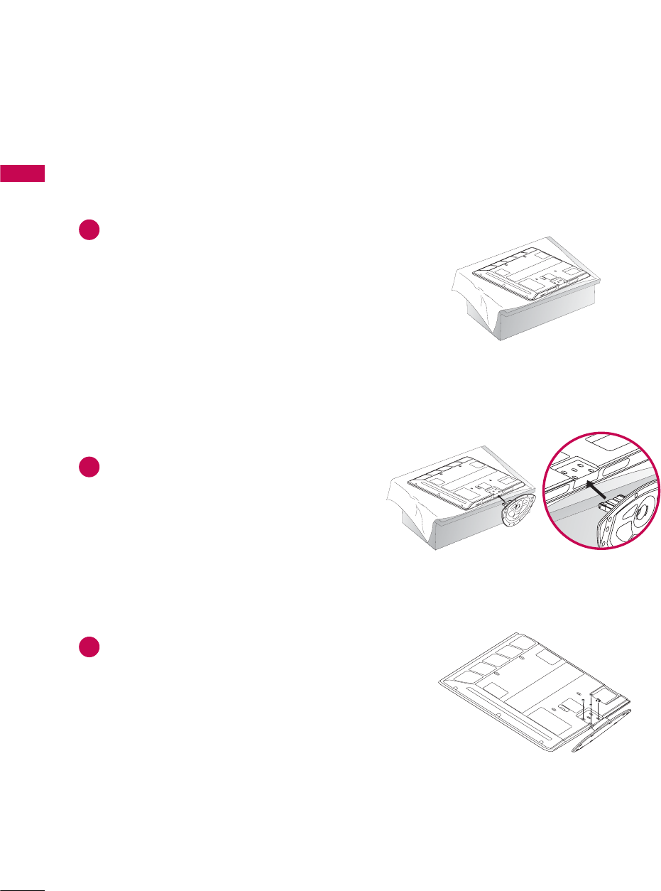
STAND INSTALLATION (Only 42PG10/20/20C)
■
Image shown may differ from your TV.
Carefully place the TV screen side down on a
cushioned surface to protect the screen from
damage.
Assemble the TV as shown.
1
2
Fix the 4 bolts securely using the holes in the
back of the TV.
3
PREPARATION
11
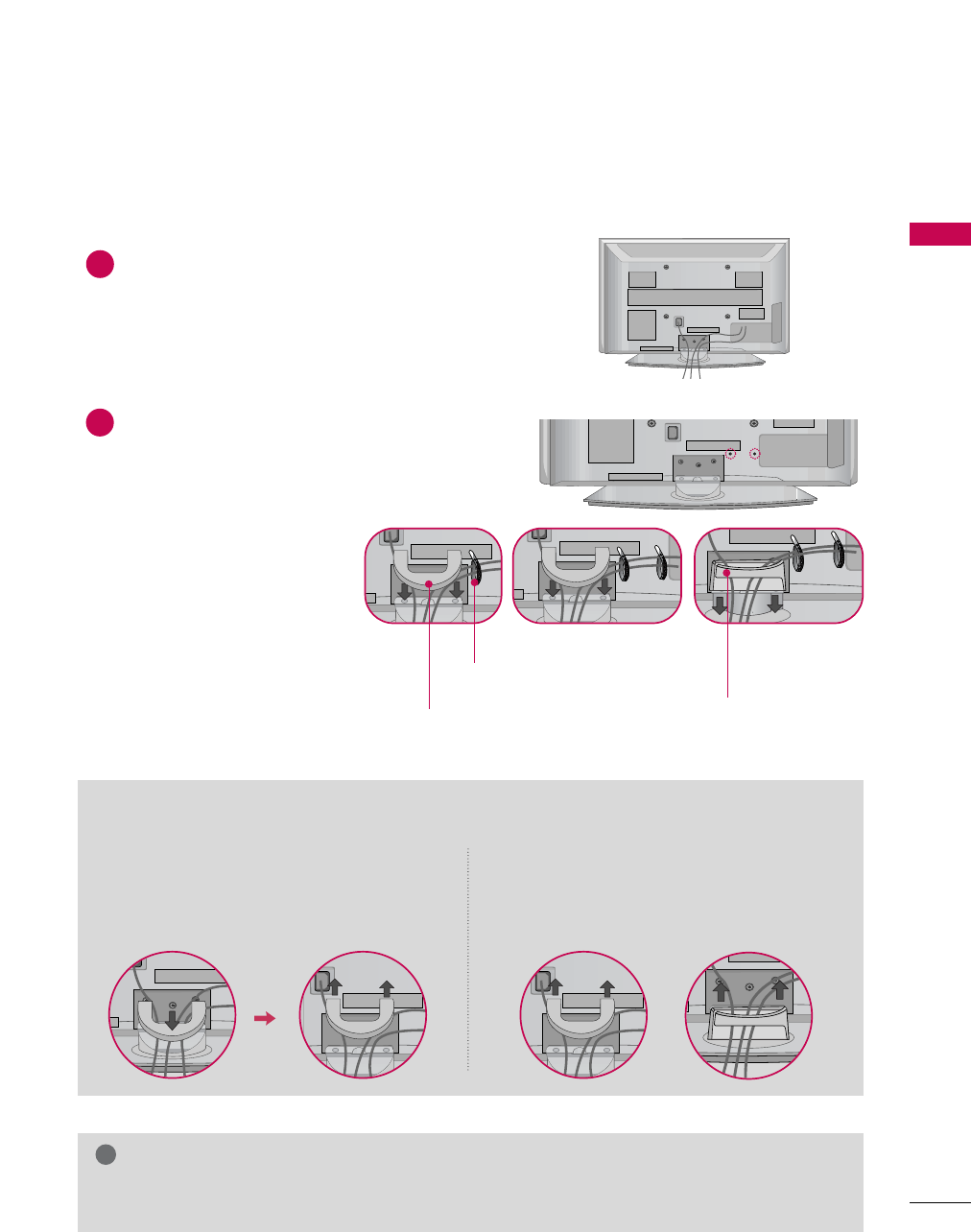
CABLE MANAGEMENT
■
Image shown may differ from your TV.
GDo not hold the CABLE MANAGEMENT CLIP when moving the TV.
- If the TV is dropped, you may be injured or the TV may be broken.
NOTE
!
Connect the cables as necessary.
To connect additional equipment, see the
EXTERNAL EQUIPMENT SETUP section.
1
Install the CABLE MANAGEMENT CLIP as
shown.
If your TV has the CABLE HOLDER, install it as
shown and bundle the cables.
2
How to remove the CABLE MANAGEMENT CLIP
42PG10/20/20C 50PG10/20/20C, 50/60PG30
GFirst, press the cable management. Hold the
CABLE MMANAGEMENT CCLIP with both
hands and pull it upward.
GHold the CABLE MANAGEMENT CLIP with
both hands and pull it backward.
CABLE HOLDER
CABLE MANAGEMENT CLIP CABLE MANAGEMENT CLIP
PREPARATION
12
DESKTOP PEDESTAL INSTALLATION
PREPARATION
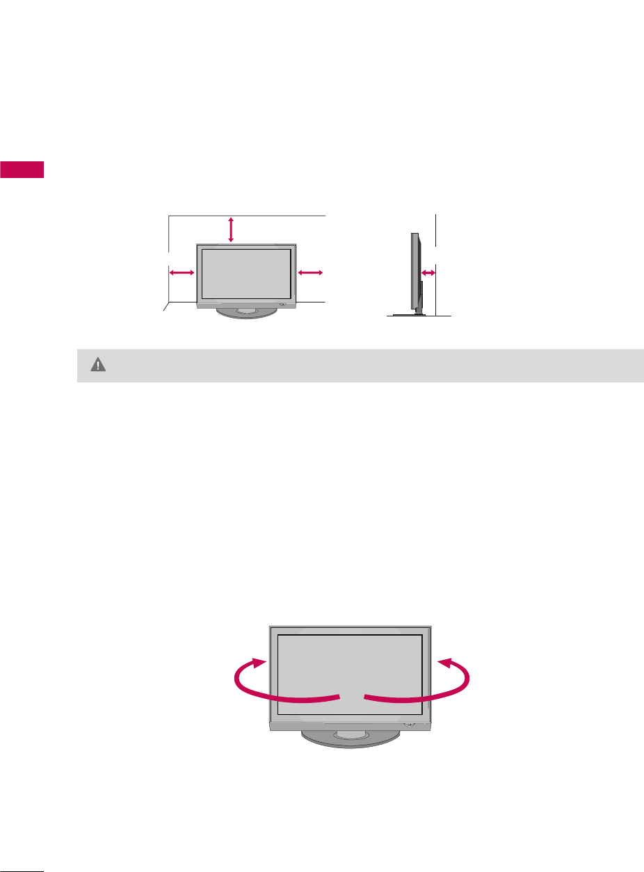
For proper ventilation, allow a clearance of 4 inches on all four sides from the wall.
■
Image shown may differ from your TV.
4 inches
4 inches
4 inches 4 inches
SWIVEL STAND (Only 50/60PG30)
After installing the TV, you can adjust the TV manually to the left or right direction by 20 degrees to suit your
viewing position.
GEnsure adequate ventilation by following the clearance recommendations.
CAUTION
PREPARATION
13
VESA WALL MOUNTING
■
Image shown may differ from your TV.
PROTECTION COVER
This TV accepts VESA FDMI compliant mounts via the four screw holes on the back of the TV. These
mounts are sold by third parties and not available from LG. Refer to the instructions included with the
mount for more info.
GScrew length needed depends on the wall mount used. For further information, refer to the instructions
included with the mount.
NOTE
!
400 mm
400 mm
You can remove the stand before installing the TV on a
wall mount by performing the previous stand instructions
in reverse. After removing the stand, install the included
protection ccover over the hole for the stand.
PREPARATION
14
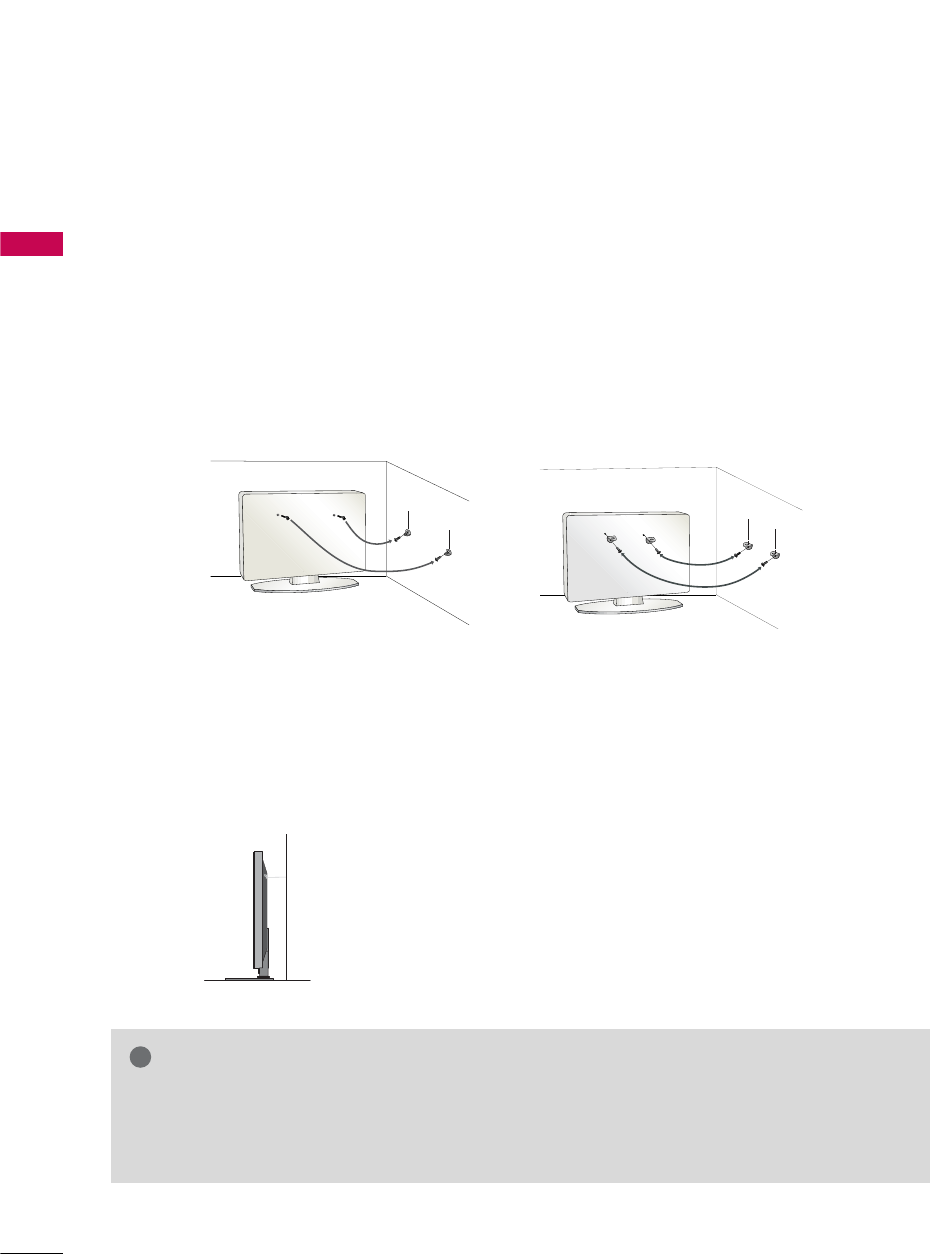
SECURING THE TV TO THE WALL TO PREVENT FALLING
PREPARATION
We recommend that you set up the TV close to a wall so it cannot fall over if pushed backwards.
Additionally, we recommend that the TV be attached to a wall so it cannot be pulled in a forward direction,
potentially causing injury or damaging the product.
Caution: Please make sure that children don’t climb on or hang from the TV.
■Insert the eye-bolts (or TV brackets and bolts) to tighten the product to the wall as shown in the picture.
*If your product has the bolts in the eye-bolts position before inserting the eye-bolts, loosen the bolts.
* Insert the eye-bolts or TV brackets/bolts and tighten them securely in the upper holes.
Secure the wall brackets with the bolts (not provided as parts of the product, must purchase separately) to
the wall. Match the height of the bracket that is mounted on the wall to the holes in the product.
Ensure the eye-bolts or brackets are tightened securely.
■Use a sturdy rope (not provided as parts of the product, must pur-
chase separately) to tie the product. It is safer to tie the rope so it
becomes horizontal between the wall and the product.
■
You should purchase necessary components to prevent TV from falling off of the stand.
■
Image shown may differ from your TV.
GUse a platform or cabinet strong enough and large enough to support the size and weight of the TV.
GTo use the TV safely, make sure that the height of the bracket on the wall and the one on the TV are
the same.
NOTE
!
PREPARATION
15
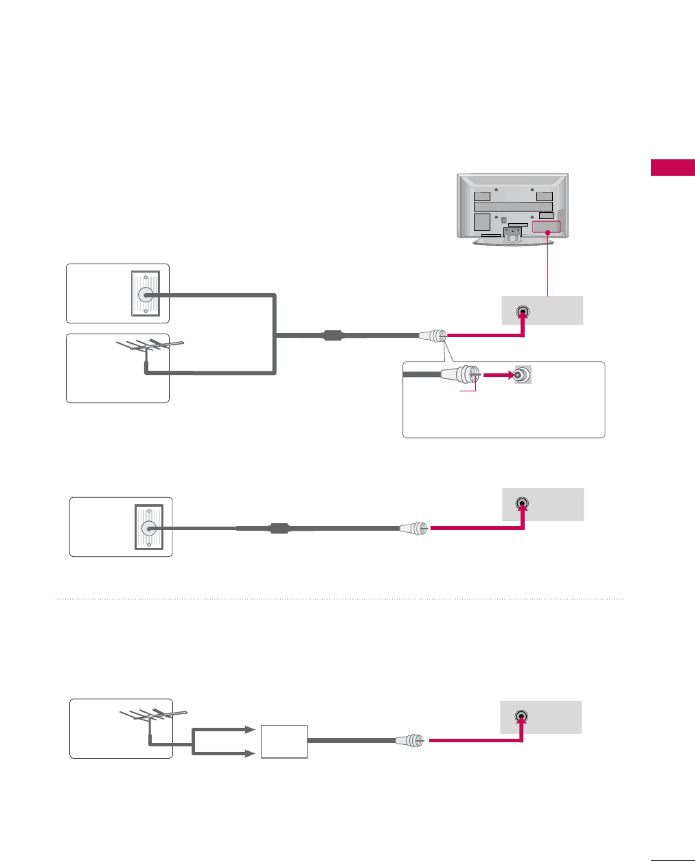
ANTENNA OR CABLE CONNECTION
1. Antenna (Analog or Digital)
Wall Antenna Socket or Outdoor Antenna without a Cable Box
Connection.
For optimum picture quality, adjust antenna direction if needed.
2. Cable
Wall
Antenna
Socket
Outdoor
Antenna
(VHF, UHF)
Cable TV
Wall Jack
Multi-family Dwellings/Apartments
(Connect to wall antenna socket)
RF Coaxial Wire (75 ohm)
RF Coaxial Wire (75 ohm)
Single-family Dwellings /Houses
(Connect to wall jack for outdoor antenna)
Be careful not to bend the copper wire
when connecting the antenna.
Copper Wire
■To improve the picture quality in a poor signal area, please purchase a signal amplifier and install properly.
■If the antenna needs to be split for two TV’s, install a 2-Way Signal Splitter.
■If the antenna is not installed properly, contact your dealer for assistance.
Antenna
UHF
Signal
Amplifier
VHF
ANTENNA/
CABLE IN
ANTENNA/
CABLE IN
ANTENNA/
CABLE IN
■To prevent damage do not connect to the power outlet until all connections are made between the devices.
EXTERNAL EQUIPMENT SETUP
16
EXTERNAL EQUIPMENT SETUP
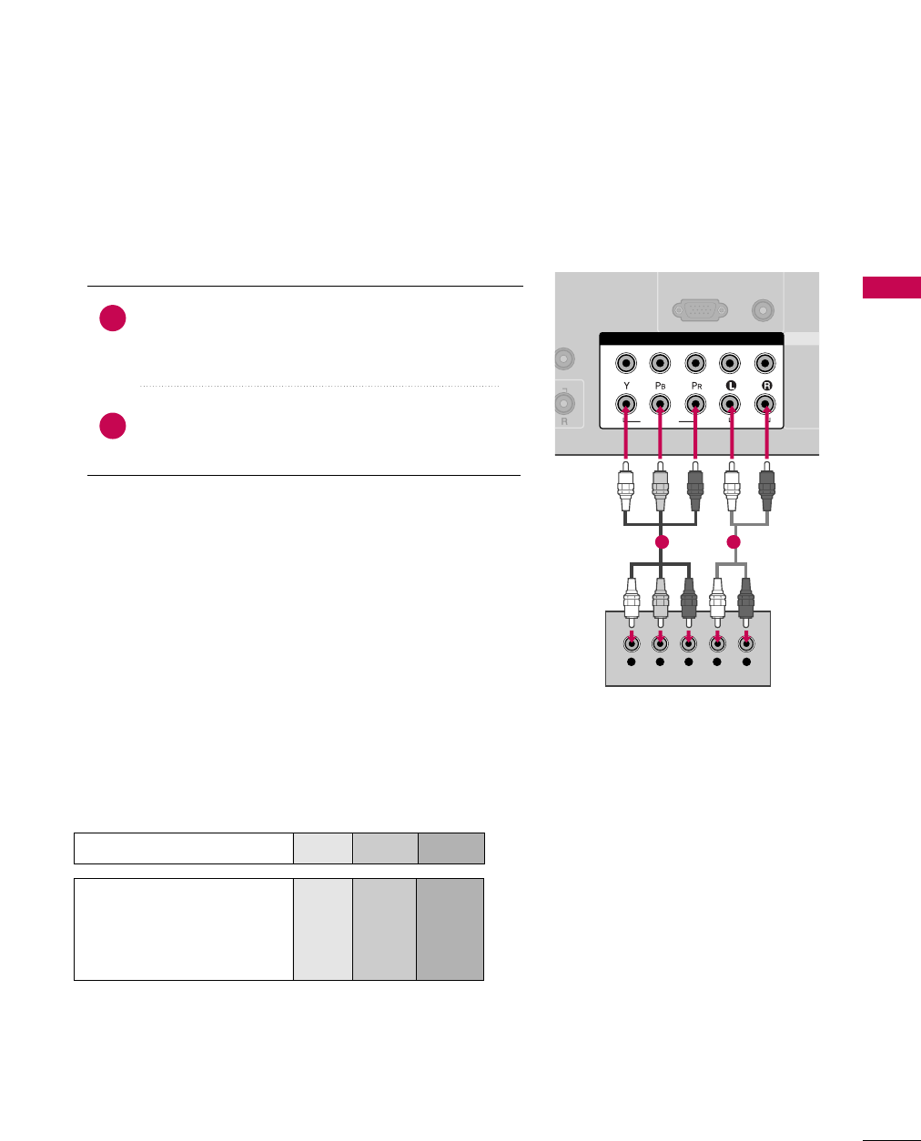
HD RECEIVER SETUP
This TV can receive Digital Over-the-air/Cable signals without an external digital set-top box. However, if you do
receive digital signals from a digital set-top box or other digital external device, refer to the figure as shown below.
Component Connection
1. How to connect
Connect the video outputs (Y, PB, PR)of the digital set-
top box to the COMPONENT IIN VVIDEO 11jacks on
the TV. Match the jack colors (Y = green, PB= blue, and
PR= red).
Connect the audio output of the digital set-top box to
the COMPONENT IIN AAUDIO 11jacks on the TV.
2
1
2. How to use
■Turn on the digital set-top box.
(Refer to the owner’s manual for the digital set-top box. operation)
■Select the Component 1 input source on the TV using
the INPUT button on the remote control.
■If connected to COMPONENT IIN2 input, select the
Component 22input source on the TV.
■To prevent the equipment damage, never plug in any power cords until you have finished connecting all equipment.
(RGB/DVI)
RGB(PC)
MOTE
TROL IN
HDMI/
2
1
COMPONENT IN
1
2
VIDEO
AUDIO
Y L RP
B
P
R
12
Y, CB/PB, CR/PR
Supported Resolutions
Horizontal Vertical
Frequency(KHz)Frequency(Hz)
15.73 59.94
15.73 60.00
31.47 59.94
31.50 60.00
44.96 59.94
45.00 60.00
33.72 59.94
33.75 60.00
27.00 24.00
33.75 30.00
67.43 59.94
67.50 60.00
Resolution
720x480i
720x480p
1280x720p
1920x1080i
1920x1080p
Signal
480i
480p
720p
108 0 i
108 0 p
Component
Yes
Yes
Yes
Yes
Yes
HDMI
No
Yes
Yes
Yes
Yes
EXTERNAL EQUIPMENT SETUP
17
HDMI Connection
Connect the digital set-top box to HDMI/DVI IIN1,
2, or HDMI IIN3 jack on the TV.
No separate audio connection is necessary.
HDMI supports both audio and video.
1. How to connect
2. How to use
■Turn on the digital set-top box.
(Refer to the owner’s manual for the digital set-top box.)
■Select the HDMI1, HDMI2, or HDMI3 input source on the
TV using the INPUT button on the remote control.
2
1
HDMI-DTV
Horizontal Vertical
Frequency(KHz)Frequency(Hz)
31.469 59.94
31.50 60.00
44.96 59.94
45.00 60.00
33.72 59.94
33.75 60.00
27.00 24.00
33.75 30.00
67.43 59.94
67.50 60.00
Resolution
720x480p
1280x720p
1920x1080i
1920x1080p
RGB IN
OMPONENT IN
AUDIO
(RGB/DVI)
RGB(PC)
HDMI/DVI IN
2
1
EO
L
B
P
R
R
AUDIO
HDMI-DTV OUTPUT
1
EXTERNAL EQUIPMENT SETUP
18
EXTERNAL EQUIPMENT SETUP
DVI to HDMI Connection
RGB IN
COMPONENT IN
AUDIO
(RGB/DVI)
RGB(PC)
CABLE IN
HDMI/DVI IN
2
1
VIDEO
LP
B
P
R
R
AUDIO
LR
DVI-DTV OUTPUT
1
2
GA DVI to HDMI cable or adapter is required for this
connection. DVI doesn't support audio, so a separate
audio connection is necessary.
NOTE
!
Connect the DVI output of the digital set-top box to
the HDMI/DVI IIN1, 2, or HDMI IIN3 jack on the
TV.
Connect the audio output of the digital set-top box to
the AUDIO ((RGB/DVI) jack on the TV.
1. How to connect
2. How to use
■Turn on the digital set-top box. (Refer to the owner’s man-
ual for the digital set-top box.)
■Select the HDMI1,HDMI2,orHDMI3 input source on the
TV using the INPUT button on the remote control.
2
1
EXTERNAL EQUIPMENT SETUP
19
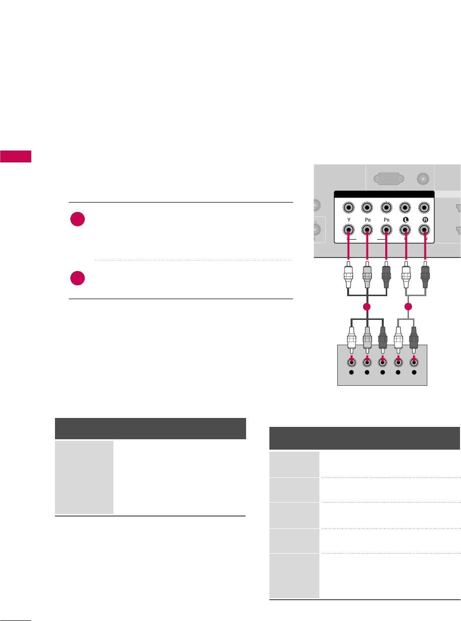
DVD SETUP
Component Connection
Component Input ports
To get better picture quality, connect a DVD player to the component input ports as shown below.
Component ports on the TV
YPBPR
Video output ports
on DVD player
Y
Y
Y
Y
PB
B-Y
Cb
Pb
PR
R-Y
Cr
Pr
Connect the video outputs (Y, PB, PR)of the DVD to the
COMPONENT IIN VVIDEO1 jacks on the TV.
Match the jack colors (Y = green, PB= blue, and PR= red).
Connect the audio outputs of the DVD to the
COMPONENT IIN AAUDIO1 jacks on the TV.
1. How to connect
2. How to use
■Turn on the DVD player, insert a DVD.
■Select the Component 1 input source on the TV using
the INPUT button on the remote control.
■If connected to COMPONENT IIN 22input, select the
Component 22input source on the TV.
■Refer to the DVD player's manual for operating instructions.
2
1
AUDIO
(RGB/DVI)
RGB(PC)
EMOTE
NTROL IN
HDM
2
1
O
COMPONENT IN
1
2
VIDEO
AUDIO
Y L RP
B
P
R
1 2
EXTERNAL EQUIPMENT SETUP
20
EXTERNAL EQUIPMENT SETUP
S-Video Connection
HDMI Connection
Connect the HDMI output of the DVD to the
HDMI/DVI IIN1, 2, or HDMI IIN3 jack on the TV.
No separate audio connection is necessary.
HDMI supports both audio and video.
1. How to connect
2. How to use
■Select the HDMI1, HDMI2, or HDMI3 input source on
the TV using the INPUT button on the remote control.
■Refer to the DVD player's manual for operating instructions.
2
1
REMOTE
CONTROL IN
RS-232C IN
(CONTROL & SERVICE)
OPTICAL
DIGITAL AUDIO OUT
1
2
Y
AUDIO
S-VIDEO
AV IN 1
VIDEO
MONO
( )
L R
S-VIDEO
AUDIO
12
OMPONENT IN
HDMI/DVI IN
2
1
DEO
LP
B
P
R
R
AUDIO
HDMI-DVD OUTPUT
1
Connect the S-VIDEO output of the DVD to the
S-VIDEO input on the TV.
Connect the audio outputs of the DVD to the AUDIO
input jacks on the TV.
1. How to connect
2. How to use
■Turn on the DVD player, insert a DVD.
■Select the AV1 input source on the TV using the INPUT
button on the remote control.
■Refer to the DVD player's manual for operating instructions.
2
1
EXTERNAL EQUIPMENT SETUP
21
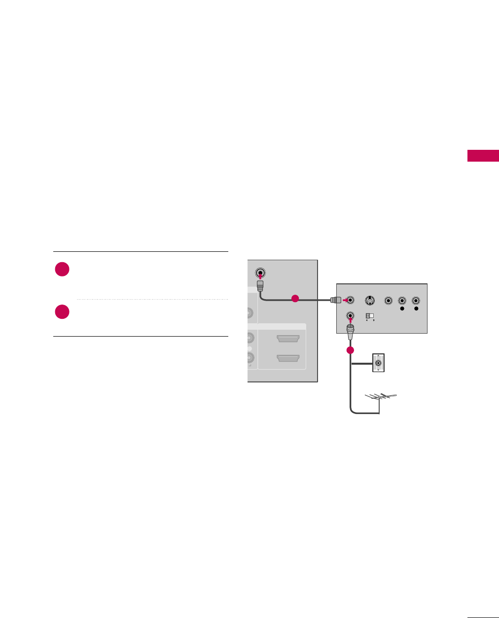
VCR SETUP
Antenna Connection
■To avoid picture noise (interference), leave an adequate distance between the VCR and TV.
■Use the ISM feature in the Option menu to avoid having a fixed image remain on the screen for a long period
of time. If the 4:3 picture format is used; the fixed images on the sides of the screen may remain visible on
the screen. This phenomenon is common to all TVs and is not covered by warranty.
IO
DVI)
ANTENNA/
CABLE IN
HDMI/DVI IN
2
1
R
L R
S-VIDEO VIDEO
OUTPUT
SWITCH
ANT IN
ANT OUT
Wall Jack
Antenna
1
2
Connect the RF antenna out socket of the
VCR to the ANTENNA/CABLE IINsocket
on the TV.
Connect the antenna cable to the RF
antenna in socket of the VCR.
1. How to connect
2. How to use
■Set VCR output switch to 3 or 4 and then
tune TV to the same channel number.
■Insert a video tape into the VCR and press
PLAY on the VCR. (Refer to the VCR owner’s
manual.)
2
1
EXTERNAL EQUIPMENT SETUP
22
EXTERNAL EQUIPMENT SETUP
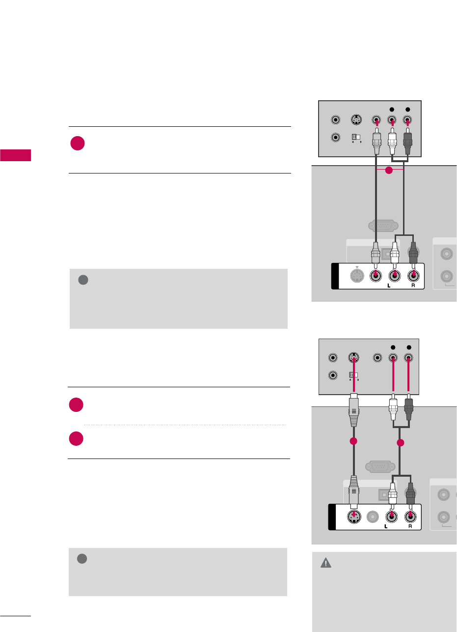
Composite (RCA) Connection
Connect the AUDIO/VIDEO jacks between TV and
VCR. Match the jack colors (Video = yellow, Audio Left
= white, and Audio Right = red)
1. How to connect
2. How to use
■Insert a video tape into the VCR and press PLAY on the
VCR. (Refer to the VCR owner’s manual.)
■Select the AV1 input source on the TV using the INPUT
button on the remote control.
■If connected to AV IIN2, select AV2 input source on the TV.
1
2. How to use
■Insert a video tape into the VCR and press PLAY on the
VCR. (Refer to the VCR owner’s manual.)
■Select the AV1 input source on the TV using the INPUT
button on the remote control.
GIf you have a mono VCR, connect the audio cable
from the VCR to the AUDIO LL/MONO jack of the
TV.
NOTE
!
REMOTE
CONTROL IN
RS-232C IN
(CONTROL & SERVICE)
OPTICAL
DIGITAL AUDIO OUT
1
2
Y
AUDIO
S-VIDEO
AV IN 1
MONO
( )
VIDEO
L R
S-VIDEO VIDEO
OUTPUT
SWITCH
ANT IN
ANT OUT
1
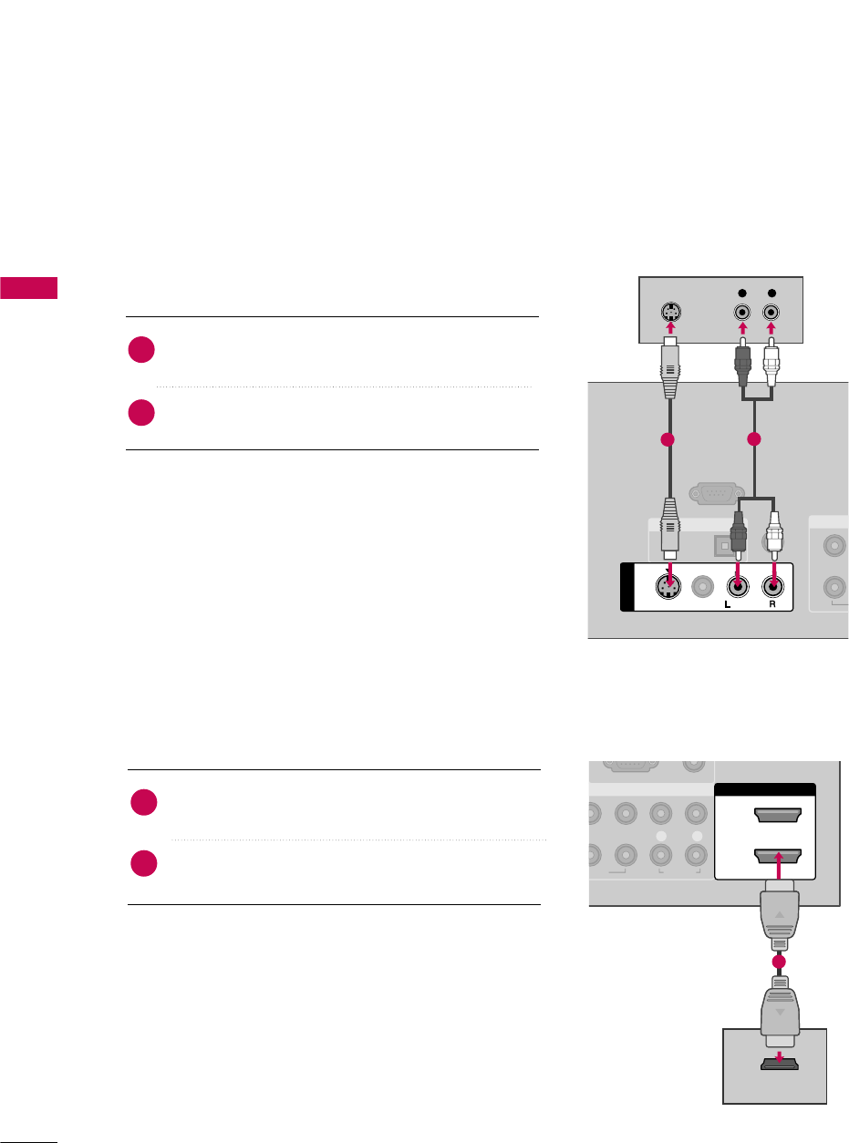
S-Video Connection
Connect the S-VIDEO output of the VCR to the
S-VIDEO input on the TV.
Connect the audio outputs of the VCR to the AUDIO
input jacks on the TV.
1. How to connect
2
1
C
REMOTE
CONTROL IN
RS-232C IN
(CONTROL & SERVICE)
OPTICAL
DIGITAL AUDIO OUT
1
2
V
Y
AUDIO
S-VIDEO
AV IN 1
VIDEO
MONO
( )
L R
S-VIDEO VIDEO
OUTPUT
SWITCH
ANT IN
ANT OUT
12
GDo not connect to both Video
and S-Video at the same time. In
the event that you connect both
Video and the S-Video cables,
only the S-Video will work.
CAUTION
GS-Video provides better quality than composite. Use
it when available.
NOTE
!
EXTERNAL EQUIPMENT SETUP
23
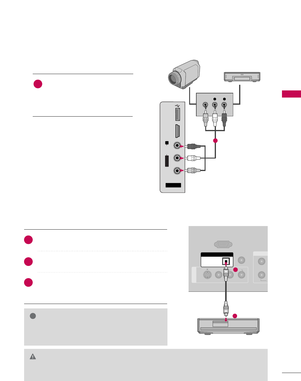
OTHER A/V SOURCE SETUP
AUDIO OUT CONNECTION
AV IN 2
L/MONO
R
AUDIO
VIDEO
HDMI IN 3
L R
VIDEO
USB
SERVUCE ONLY
Camcorder
Video Game Set
Connect the AUDIO/VIDEO jacks
between TV and external equipment.
Match the jack colors
.
(Video = yellow, Audio Left = white, and
Audio Right = red)
1. How to connect
2. How to use
■Select the AV2 input source on the TV using
the INPUT button on the remote control.
■If connected to AV IIN1 input, select the A V 1
input source on the TV.
■Operate the corresponding external equipment.
1
1
REMOTE
CONTROL IN
RS-232C IN
(CONTROL & SERVICE)
AV IN 1
AUDIO
S-VIDEO
1
2
Y
OPTICAL
DIGITAL AUDIO OUT
1
2
GWhen connecting with external audio equipments, such as
amplifiers or speakers, you can turn the TV speakers off in
the menu. (Gp.61)
NOTE
!
GDo not look into the optical output port. Looking at the laser beam may damage your vision.
GGBlock the SPDIF out (optical) about the contents with ACP (Audio Copy Protection) function.
CAUTION
Connect one end of the optical cable to the TV’s OPTICAL
port of DIGITAL AAUDIO OOUT.
Connect the other end of the optical cable to the digital
audio input on the audio equipment.
Set the “TV Speaker option - Off” in the AUDIO menu. (G
p.61). See the external audio equipment instruction manual
for operation.
1. How to connect
2
3
1
Send the TV’s audio to external audio equipment via the Audio Output port.
EXTERNAL EQUIPMENT SETUP
24
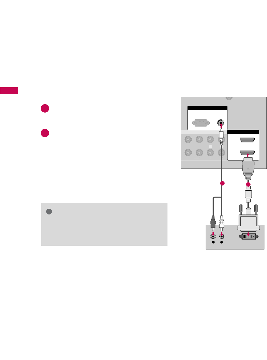
PC SETUP
EXTERNAL EQUIPMENT SETUP
DVI to HDMI Connection
This TV provides Plug and Play capability, meaning that the PC adjusts automatically to the TV's settings.
VGA (D-Sub 15 pin) Connection
RGB IN
COMPONENT IN
AUDIO
(RGB/DVI)
RGB(PC)
N
HDMI/DV
2
1
1
2
VIDEO
LYP
B
P
R
R
AUDIO
AUDIO
RGB OUTPUT
1 2
RGB IN
COMPONENT IN
AUDIO
(RGB/DVI)
RGB(PC)
HDMI/DVI IN
2
1
VIDEO
LP
B
P
R
R
AUDIO
DVI-PC OUTPUTAUDIO
1 2
2. How to use
■Turn on the PC and the TV.
■Select the RGB-PC input source on the TV using the
INPUT button on the remote control.
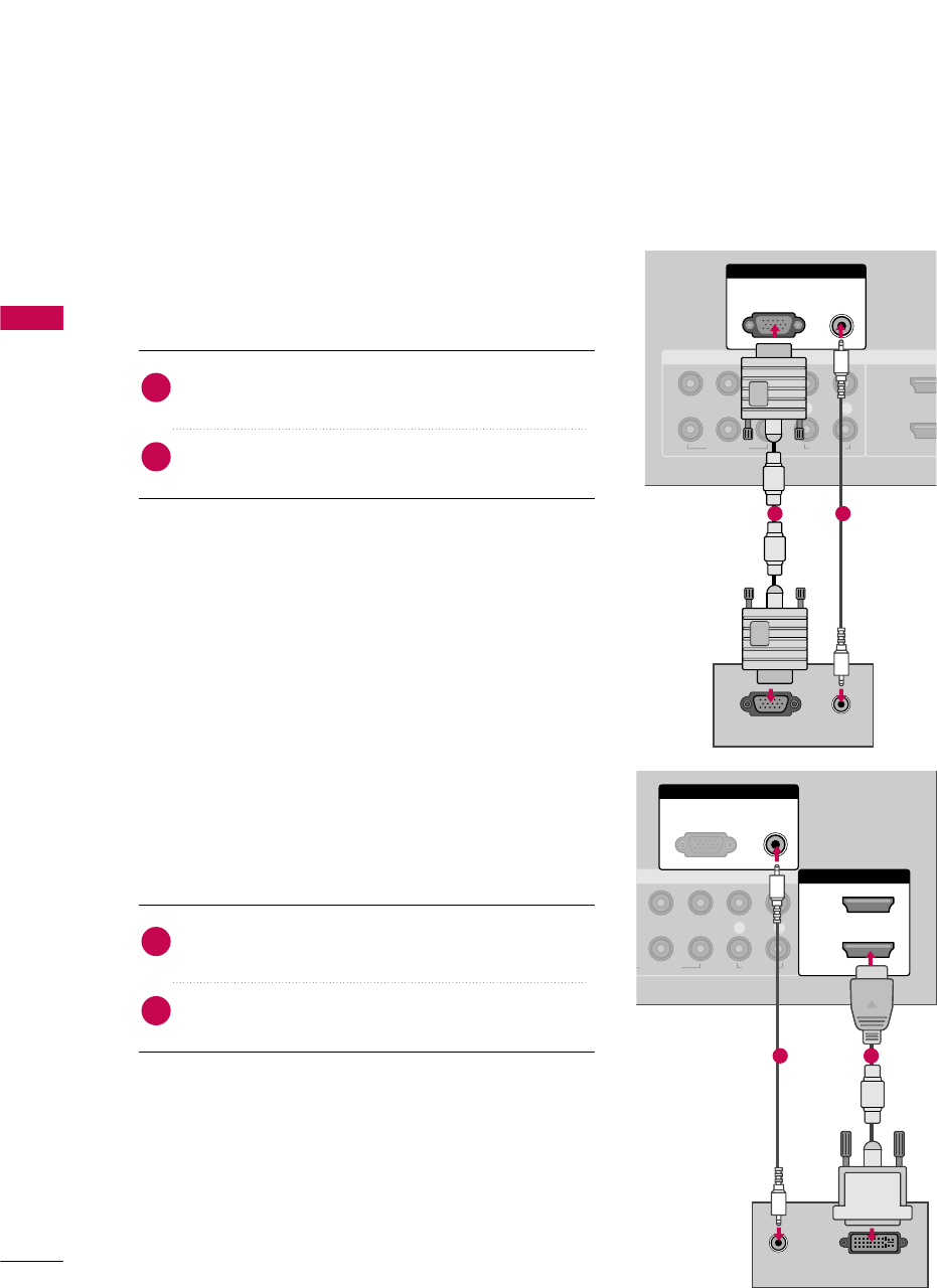
Connect the VGA output of the PC to the RGB (P C)
jack on the TV.
Connect the PC audio output to the AUDIO
(RGB/DVI)jack on the TV.
1. How to connect
2
1
2. How to use
■Turn on the PC and the TV.
■Select the HDMI1,HDMI2 or HDMI3 input source on the
TV using the INPUT button on the remote control.
Connect the DVI output of the PC to the HDMI/DVI
IN 11, 22, or HDMI IIN3 jack on the TV.
Connect the PC audio output to the AUDIO
(RGB/DVI) jack on the TV.
1. How to connect
2
1
EXTERNAL EQUIPMENT SETUP
32
EXTERNAL EQUIPMENT SETUP
Horizontal Vertical
Frequency(KHz)Frequency(Hz)
31.469 70.08
31.469 70.08
31.469 59.94
37.879 60.31
48.363 60.00
47.776 59.87
47.720 59.799
47.130 59.65
Resolution
720x400
1360x768
640x350
640x480
800x600
1024x768
1280x768
1366x768
Supported Display Specifications (RGB-PC, HDMI-PC)
For 26/32/37/42LG30 For 37/42/47/52LG50,32/37/42/47/52LG60
32/42/47/52LG70
* Only RGB-PC mode
GDepending on graphic card and signal status, there can be some shaking to find best picture in a little time.
NOTE
!
Resolution
720x400
1360x768
640x350
640x480
800x600
1024x768
1280x1024
1600x1200
1920x1080
RGB-PC
1920x1080
HDMI-PC
1280x768
Horizontal Vertical
Frequency(KHz)Frequency(Hz)
31.468 70.09
31.469 70.08
31.469 59.94
37.500 75.00
37.861 72.80
35.156 56.25
37.879 60.31
46.875 75.00
48.077 72.18
48.363 60.00
56.476 70.06
60.023 75.02
47.776 59.87
60.289 74.893
63.981 60.02
79.976 75.025
47.712 60.015
75.00 60.00
66.587 59.934
67.5 60.00
* Only RGB-PC mode
EXTERNAL EQUIPMENT SETUP
26
EXTERNAL EQUIPMENT SETUP
Screen Setup for PC mode
Selecting Resolution
You can choose the resolution in RGB-PC mode.
The Position, Phase, and Size can also be adjusted.
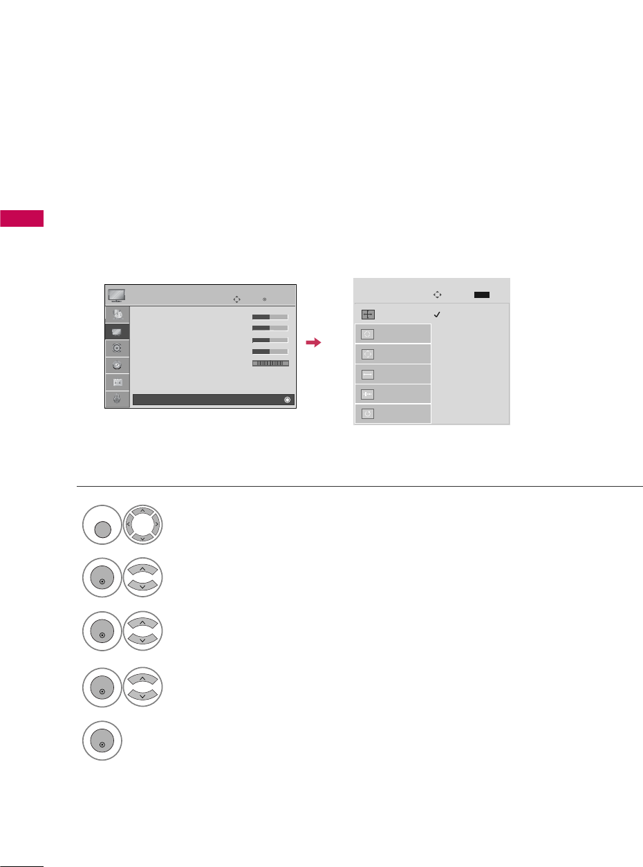
Select PICTURE.
Select Screen ((RGB-PC).
Select Resolution.
Select the desired resolution.
1024 x 768
1280 x 768
1360 x 768
Auto config.
Resolution
G
Position
Size
Phase
Reset
Screen
Move
Prev.
MENU
1
MENU
3
4
2
ENTER
ENTER
ENTER
5
ENTER
Enter
Move
PICTURE
• Contrast 50
• Brightness 50
• Sharpness 50
• Color 50
• Tint 0
• Advanced Control
• Reset
Screen (RGB-PC)
RG
E
EXTERNAL EQUIPMENT SETUP
27
Auto Configure
Automatically adjusts picture position and minimizes image instability. After adjustment, if the image is still
not correct, try using the manual settings or a different resolution or refresh rate on the PC.
Select Screen ((RGB-PC).
Select Auto cconfig..
Auto config. G
Resolution
Position
Size
Phase
Reset
Screen
Move
Prev.
MENU
To Set
3
2
ENTER
ENTER
Select Yes.
4
ENTER
Start Auto Configuration.
5
ENTER
Select PICTURE.
1
MENU
• If the position of the image is still not
correct, try Auto adjustment again.
• If picture needs to be adjusted again
after Auto adjustment in RGB-PC, you
can adjust the P os itio n, Size or
Phase.
Enter
Move
PICTURE
• Contrast 50
• Brightness 50
• Sharpness 50
• Color 50
• Tint 0
• Advanced Control
• Reset
Screen (RGB-PC)
RG
E
Yes No
EXTERNAL EQUIPMENT SETUP
28
EXTERNAL EQUIPMENT SETUP
Adjustment for screen Position, Size, and Phase
If the picture is not clear after auto adjustment and especially if characters are still trembling, adjust the picture
phase manually.
This feature operates only in RGB-PC mode.
Select Position, Size, or Phase.
Make appropriate adjustments.
Auto config.
Resolution
Position
G
Size
Phase
Reset
GF
D
E
Screen
Move
Prev.
MENU
3
ENTER
4
ENTER
■Position: This function is to adjust pic-
ture to left/right and up/down as you
prefer.
■Si ze: This function is to minimize any
vertical bars or stripes visible on the
screen background. And the horizontal
screen size will also change. The Size
adjustment range is -30 ~30.
■Phase: This function allows you to
remove any horizontal noise and clear or
sharpen the image of characters. The
Phase adjustment range is -32 ~31.
Select PICTURE.
Select Screen ((RGB-PC).
1
MENU
2
ENTER
Enter
Move
PICTURE
• Contrast 50
• Brightness 50
• Sharpness 50
• Color 50
• Tint 0
• Advanced Control
• Reset
Screen (RGB-PC)
RG
E
5
ENTER
EXTERNAL EQUIPMENT SETUP
29
Screen Reset (Reset to original factory values)
Returns Position, Size, and Phase to the default factory settings.
This feature operates only in RGB-PC mode.
Select Reset.
3
ENTER
Select PICTURE.
Select Screen ((RGB-PC).
1
MENU
2
ENTER
Select Yes.
4
ENTER
5
ENTER
Auto config.
Position
Resolution
Size
Phase
Reset
G
Screen
Move
Prev.
MENU
Initialize Settings.
Enter
Move
PICTURE
• Contrast 50
• Brightness 50
• Sharpness 50
• Color 50
• Tint 0
• Advanced Control
• Reset
Screen (RGB-PC)
RG
E
Yes No
WATCHING TV / CHANNEL CONTROL
30
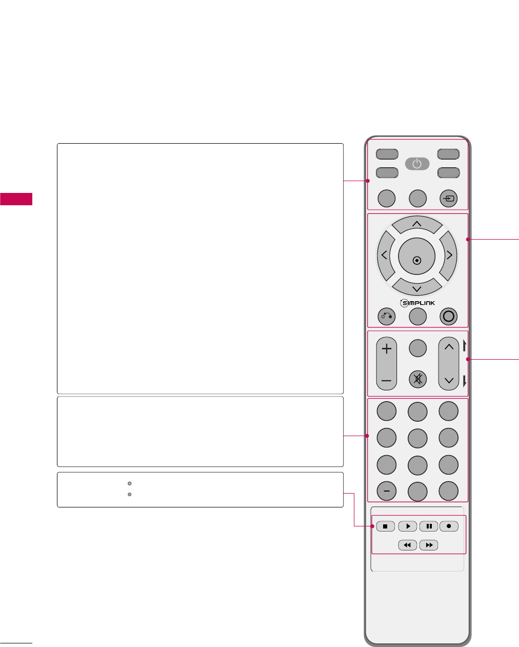
REMOTE CONTROL FUNCTIONS
WATCHING TV / CHANNEL CONTROL
When using the remote control, aim it at the remote control sensor on the TV.
INPUT
FAV
MUTE
RATIO
SOUND
POWER
Q. MENU MENU
AV MODERETURN
ENTER
VOL CH
123
456
78
0
9
FLASHBK
P
A
G
E
SLEEP
PICTURE
RATIO
SLEEP
PICTURE
SOUND
POWER
Q.MENU
MENU
INPUT
— (DASH)
FLASHBK
Change the aspect ratio.Gp.44
Select the amount of time before your TV turns off auto-
matically.Gp.72
Selects the factory preset picture depend on the viewing
environment. Gp.46
Selects the factory preset sound for type of program.
Gp.58
Turns your TV on or off.
Select the desired quick menu source. Gp.33
Displays the main menu.
Clear all on-screen displays and return to TV viewing from
any menu.
External input modes rotate in regular sequence. Gp.38
Used to enter a program number for multiple
program channels such as 2-1, 2-2, etc.
Tune to the last channel viewed.
Control video cassette recorders or DVD players.
Control the SIMPLINK compatible devices.
NUMBER button
VCR/DVD,
SIMPLINK
Control buttons
WATCHING TV / CHANNEL CONTROL
31
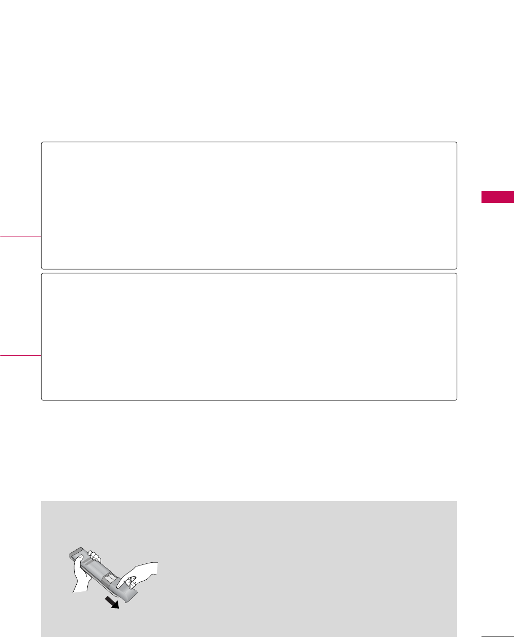
Installing Batteries
■
Open the battery compartment cover on the back side and install
the batteries matching correct polarity (+with +,-with -).
■
Install two 1.5V AAA batteries. Don’t mix old or used batteries with
new ones.
■
Close cover.
THUMBSTICK
(Up/Down/Left
Right/ENTER)
RETURN
SIMPLINK
AV MODE
VOLUME UP
/DOWN
FAV
MUTE
CHANNEL
UP/DOWN
PAGE
UP/DOWN
Navigate the on-screen menus and adjust the system settings to your preference.
Allows the user to move return one step in an interactive application or other user interaction
function.
See a list of AV devices connected to TV.
When you toggle this button, the SIMPLINK menu appears at the screen. Gp.42
It helps you select and set images and sounds when connecting AV devices. Gp.40
Increase/decrease the sound level.
Scroll through the programmed Favorite channels. Gp.33
Switch the sound on or off. Gp.32
Select available channels.
Move from one full set of screen information to the next one.
WATCHING TV / CHANNEL CONTROL
32
TURNING ON TV
WATCHING TV / CHANNEL CONTROL
NOTE
!
GIf you intend to be away on vacation, disconnect the power plug from the wall power outlet.
First, connect power cord correctly.
At this moment, the TV switches to standby mode.
■In standby mode to turn TV on, press the , INPUT,CH ((Dor E)
button on the TV or press the POWER, INPUT, CH( or ),
Number ((0~9 ) button on the remote control.
Select the viewing source by using the INPUT button on the remote control.
■This TV is programmed to remember which power state it was last set to,
even if the power cord is out.
When finished using the TV, press the POWER button on the remote con-
trol. The TV reverts to standby mode.
1
2
3
Press the CH ( or )or NUMBER buttons to select a channel number.
1
VOLUME ADJUSTMENT
CHANNEL SELECTION
Press the VOL (+ or -) button to adjust the volume.
If you want to switch the sound off, press the MUTE button.
You can cancel the Mute function by pressing the MUTE or VOL (+ or -)
button.
Adjust the volume to suit your personal preference.
1
2
3
WATCHING TV / CHANNEL CONTROL
33
QUICK MENU
Display each menu.
Make appropriate adjustments.
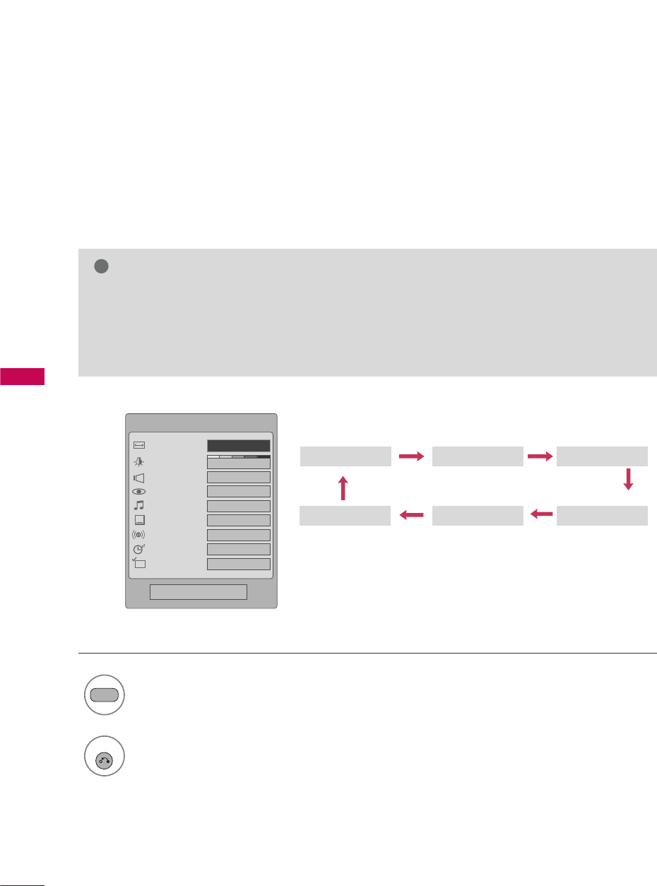
■Aspect RRatio: Selects your desired picture format.
■Power SSavi ng: Adjusts screen brightness to
reduce the power consumption of the TV.
■Clear VVoice: By differentiating the human sound
range from others, it helps make human voices
sound better.
■Picture MMode: Selects the factory preset picture
depend on the viewing environment.
■Sound MMode: Selects the factory preset sound for
type of program.
■Caption: Select on or off.
■Multi AAudio: Changes the audio language (Digital
signal).
SAP: Selects MTS sound (Analog signal).
■Sleep TTimer: Select the amount of time before
your TV turns off automatically.
■Del/Add/Fav: Select channel you want to add/delete
or add the channel to the Favorite List.
Your TV's OSD (On Screen Display) may differ slightly from what is shown in this manual.
Q.Menu (Quick Menu) is a menu of features which users might use frequently.
1
Q. MENU
2
Q.Menu
Close
3
F16:9 G
Vivid
Off
Standard
Off
English
Off
Add
Aspect Ratio
Power Saving
Clear Voice
Picture Mode
Sound Mode
Caption
Multi Audio
Sleep Timer
Del/Add/Fav
CH
3
Q. MENU
Return to TV viewing.
WATCHING TV / CHANNEL CONTROL
34
WATCHING TV / CHANNEL CONTROL
ON-SCREEN MENUS SELECTION
Your TV's OSD (On Screen Display) may differ slightly from that shown in this manual.
Display each menu.
Select a menu item.
Enter to the pop up menu.
1
MENU
3
2
ENTER
ENTER
Return to TV viewing.
4
MENU
Enter
Move
Auto Tuning
Manual Tuning
Channel Edit
CHANNEL
CHANNEL
TIME
PICTURE
OPTION
AUDIO
LOCK
Enter
Move
Aspect Ratio : 16:9
Picture Mode : Standard
• Contrast 90
• Brightness 50
• Sharpness 60
• Color 60
• Tint 0
• Advanced Control
PICTURE
E
Enter
Move
Auto Volume : Off
Clear Voice : On
Balance 0
Sound Mode : Standard
•
SRS TruSurround XT:
Off
• Treble 50
• Bass 50
• Reset
AUDIO
E
LR
Enter
Move
Clock :
Feb/21/2008/ 2:10 AM
Off Time : Off
On Time : Off
Sleep Timer : Off
Auto Sleep : Off
TIME
Enter
Move
Lock System : Off
Set Password
Block Channel
Movie Rating
TV Rating-Children
TV Rating-General
Downloadable Rating
Input Block
LOCK
Enter
Move
Language : English
Input Label
SIMPLINK : On
Key Lock : Off
Caption : Off
ISM Method : Normal
Power Saving : Level 0
Set ID : 1
OPTION
RG
Lock System : Off
Set Password
Block Channel
TV Rating-English
TV Rating-French
Downloadable Rating
Input Block
For USA For Canada
WATCHING TV / CHANNEL CONTROL
35
CHANNEL SETUP
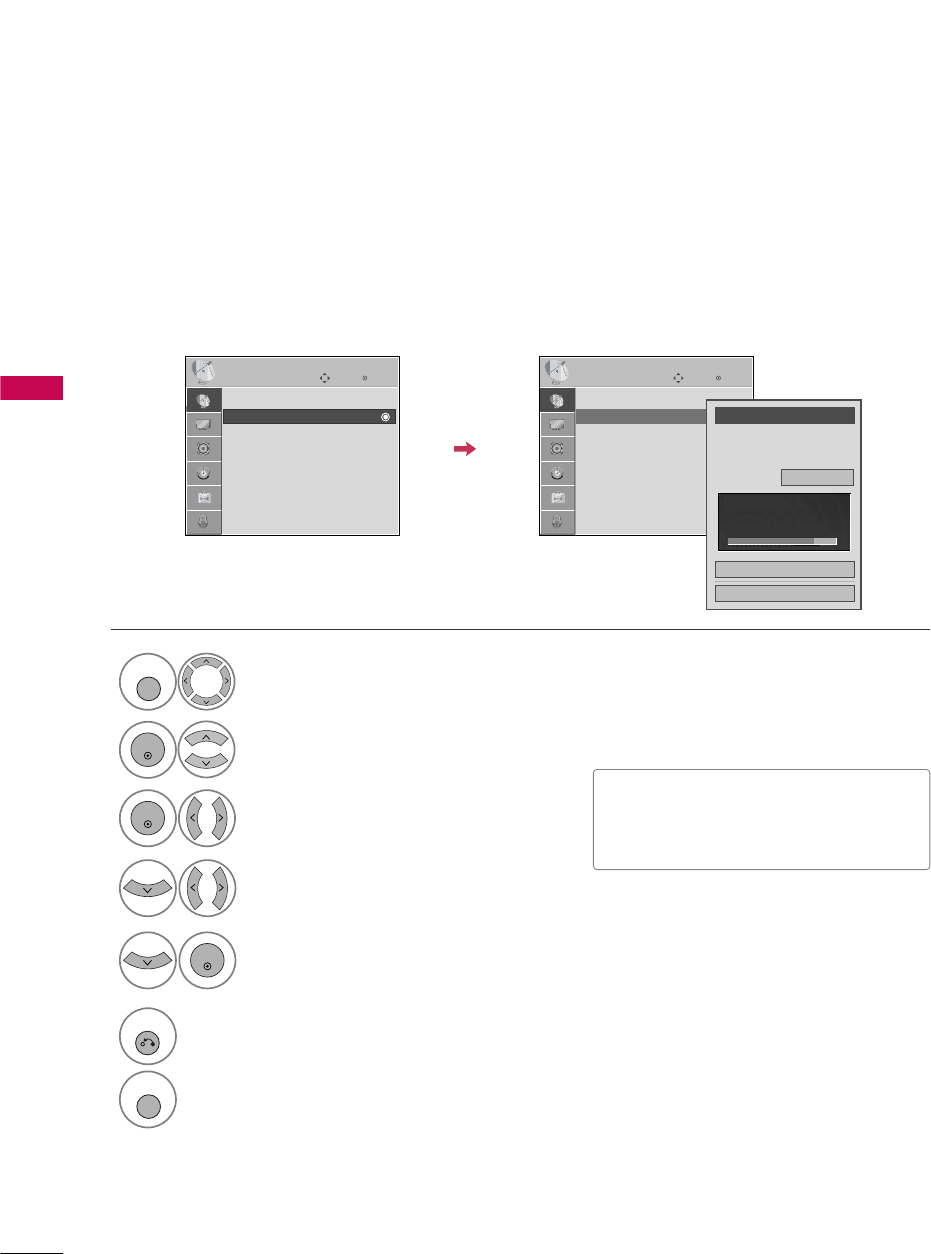
Auto Scan (Auto Tuning)
Automatically finds all channels available through antenna or cable inputs, and stores them in memory on the
channel list.
Run Auto Tuning again after any Antenna/Cable connection changes.
Select CHANNEL.
Select Auto TTuning.
Select Yes.
Run Auto ttuning.
1
MENU
3
2
ENTER
ENTER
4
ENTER
■A password is required to gain access to
Auto Tuning menu if the Lock System is
turned on.
5
RETURN
Return to the previous menu.
MENU
Return to TV viewing.
Enter
Move
CHANNEL
Auto Tuning
Manual Tuning
Channel Edit
Enter
Move
CHANNEL
Auto Tuning
Manual Tuning
Channel Edit
Press ‘Yes’ button to begin
auto tuning.
Yes
No
WATCHING TV / CHANNEL CONTROL
36
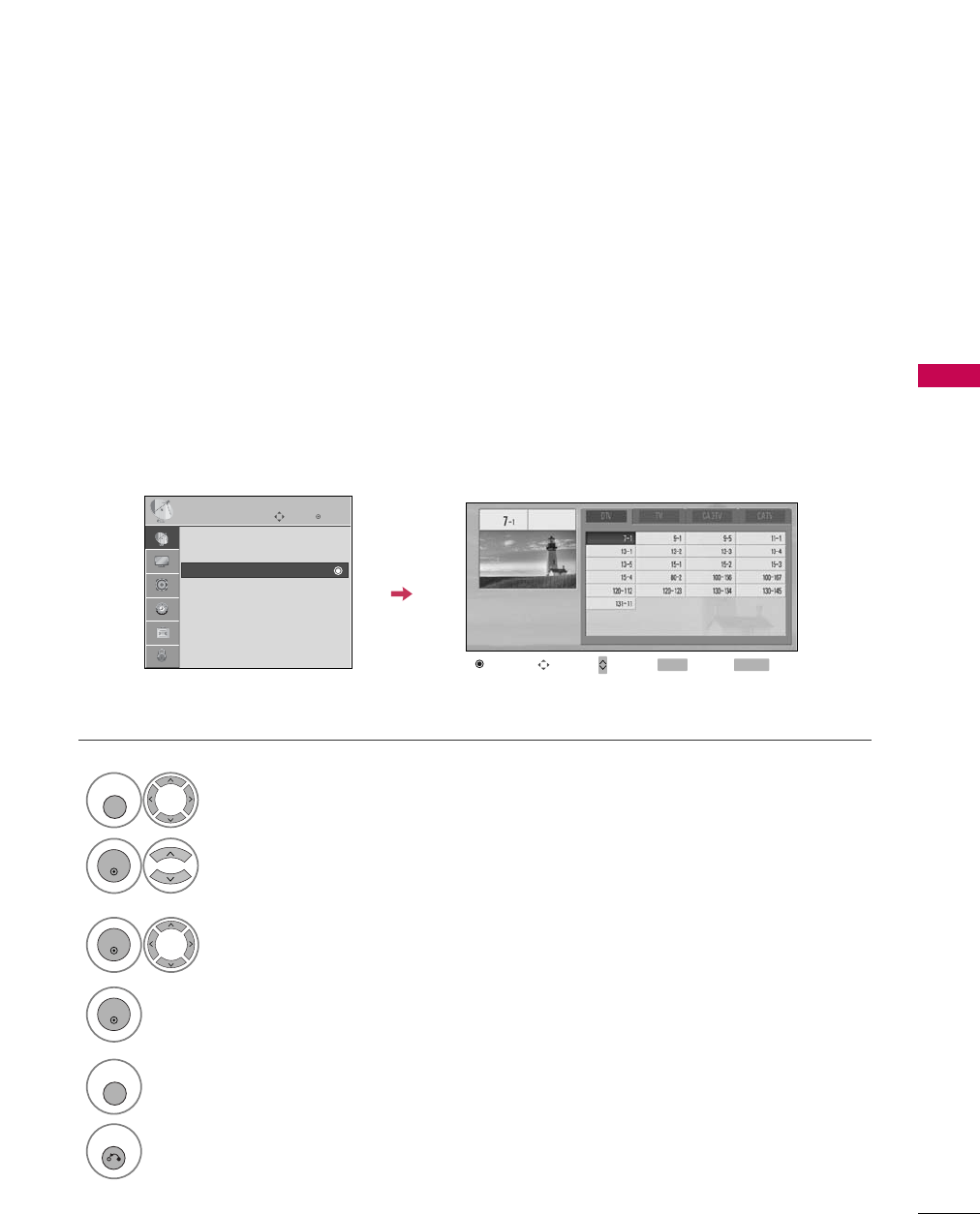
WATCHING TV / CHANNEL CONTROL
Select CHANNEL.
1
MENU
2
ENTER
If selecting DTV or CADTV input signal, you can view the on-screen signal strength monitor to see the quality
of the signal being received.
Add/Delete Channel (Manual Tuning)
Select Manual TTuning.
Select DTV, T V, CADTV, or CATV.
Select channel you want to add
or delete.
3
ENTER
4
Select Ad d or Delete.
5
ENTER
■A password is required to gain access to
Manual Tuning menu if the Lock System
is turned on.
6
RETURN
Return to the previous menu.
MENU
Return to TV viewing.
Enter
Move
CHANNEL
Auto Tuning
Manual Tuning
Channel Edit
Enter
Move
CHANNEL
Auto Tuning
Manual Tuning
Channel Edit
Channel
Select channel type and
RF-channel number.
F
DTV
G
2
Close
Delete
DTV 2-0
Bad Normal Good
WATCHING TV / CHANNEL CONTROL
37
CHANNEL SETUP
Select a channel.
Select channel you want to add or
delete.
3
ENTER
4
ENTER
From the default channel list created from the Auto Tuning channel search, you can create two different types
of channel lists in memory: “custom list” and “favorite channel list”.
A custom list can be created by toggling each channel on or off with ENTER button. The channels in the Custom
List are displayed in black and the channels deleted from the Custom List are displayed in gray.
Once a channel is highlighted you can add or delete the channel by referring to the small window at the top-
right corner of the screen.
Channel Editing
Select CHANNEL.
1
MENU
2
ENTER
Select Channel EEdit.
RETURN
Return to TV viewing.
Return to the previous menu.
5
MENU
Add/Delete Move Page
CH
Move Previous RETURN Exit
MENU
Enter
Move
CHANNEL
Auto Tuning
Manual Tuning
Channel Edit
WATCHING TV / CHANNEL CONTROL
38
INPUT LIST
WATCHING TV / CHANNEL CONTROL
Only these input signals which are connected to a TV can be activated and selected.
Select the desired input source.
1
INPUT
TV AV1 AV2 Component1
HDMI3 HDMI2 HDMI1 RGB-PC
Component2
TV AV1 AV2 Component1 Component2
ENTER
■T V: Select it to watch over-the-air, cable
and digital cable broadcasts.
■AV 11-2: Select them to watch a VCR or
other external equipment.
■Component 11-2: Select them to
watch DVD or a Digital set-top box.
■RGB-PC: Select it to view PC input.
■HDMI1-3: Select them to watch high
definition devices.
TV AV1 AV2 Component1 Component2
Input Label
Q.MENU Exit
RETURN
Select a desired input source (except T V).
Then, you can select your desired Input
Label with using Q.MENU button. Gp.39
Disconnected input is inactivated.
WATCHING TV / CHANNEL CONTROL
39
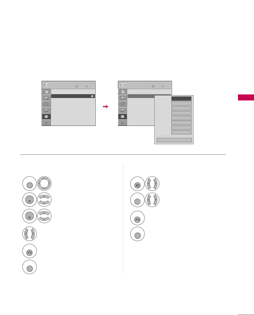
INPUT LABEL
You can set a label for each input source when it's not in use.
Select OPTION.
Select Input LLabel.
Select the label.
1
MENU
2
ENTER
Select the source.
3
ENTER
4
5
RETURN
Return to the previous menu.
MENU
Return to TV viewing.
With using OPTION menu
Select the source.
Select the label.
1
INPUT
2
Q. MENU
3
RETURN
Return to the previous menu.
MENU
Return to TV viewing.
With using INPUT button
Enter
Move
OPTION
Language : English
Input Label
SIMPLINK : On
Key Lock : Off
Caption : Off
ISM Method : Normal
Power Saving : Level 0
Set ID : 1
Enter
Move
OPTION
Language : English
Input Label
SIMPLINK : On
Key Lock : Off
Caption : Off
ISM Method : Normal
Power Saving : Level 0
Set ID : 1
AV1
AV2
Component1
Component2
RGB-PC
HDMI1
HDMI2
HDMI3
F G
Close
WATCHING TV / CHANNEL CONTROL
40
AV MODE
WATCHING TV / CHANNEL CONTROL
You can select the optimal images and sounds.
1
AV MODE
Off Cinema
Game Sport
Press the AV MMODE button repeatedly to select the desired source.
■If you select “Cinema” in AV mode,
Cinema will be selected both for “PIC-
TURE menu - Picture Mode” and “AUDIO
menu - Sound Mode” respectively.
■If you select “Of f” in AV mode, the
“Picture MMode” and “Sound MMode”
return to previous selected value.
2
RETURN
Return to TV viewing.
WATCHING TV / CHANNEL CONTROL
41
This function operates only with devices with the logo.
If connected other brand device with the logo, it may not work.
This allows you to control and play other AV devices connected with HDMI cable without additional cables and
settings.
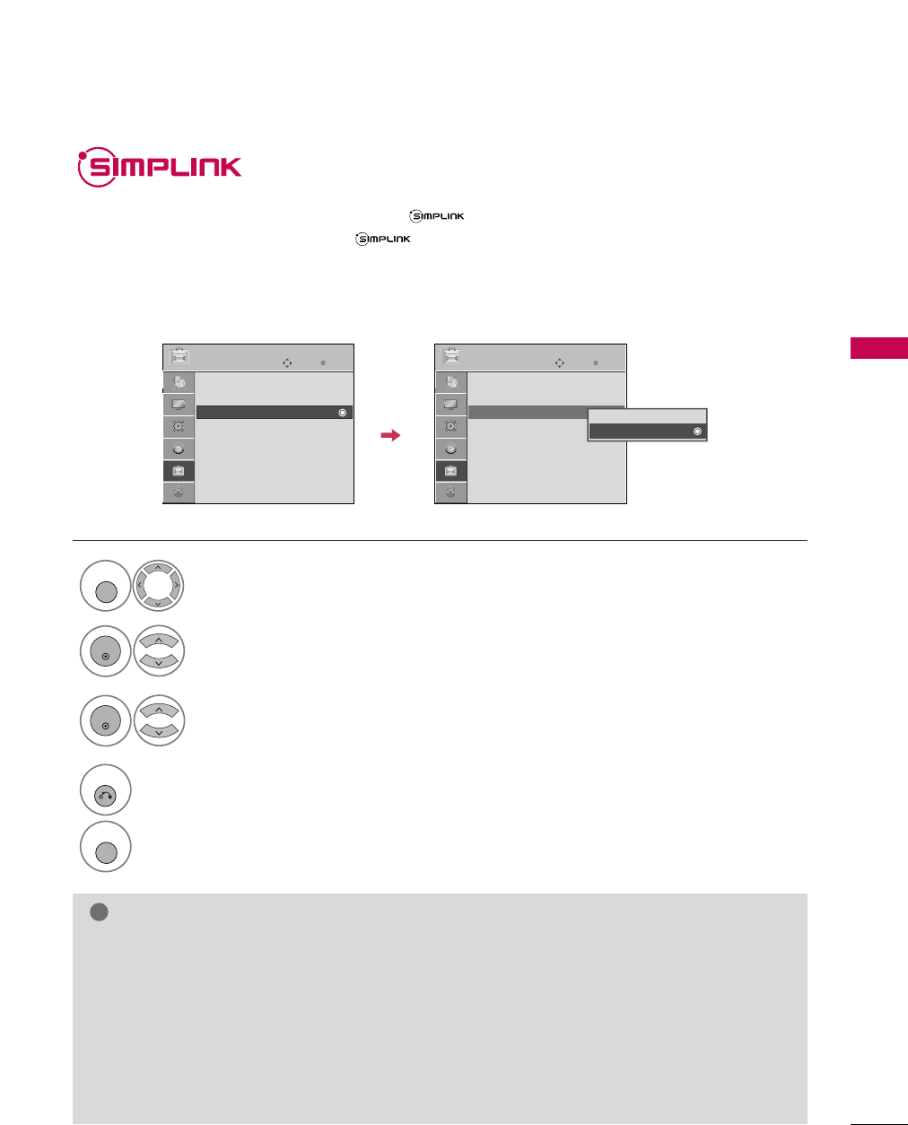
To start using SIMPLINK, turn it on in the user menus.
Select OPTION.
Select SIMPLINK.
Select On or Off.
1
MENU
3
2
ENTER
ENTER
NOTE
!
GConnect the HDMI/DVI IN or HDMI IN terminal of the TV to the rear terminal (HDMI terminal) of the SIM-
PLINK device with the HDMI cable.
GWhen you switch the Input source with the INPUT button on the remote control, the SIMPLINK device will
stop.
GWhen you select a device with home theater functionality, the sound output automatically switches to the
home theater speakers.
GIf a connected SIMPLINK home theater system doesn't play the audio from the TV, connect the DIGITAL
AUDIO OUT terminal on the back of the TV to the DIGITAL AUDIO IN terminal on the back of the SIM-
PLINK device with an OPTICAL cable.
4
RETURN
Return to the previous menu.
MENU
Return to TV viewing.
Enter
Move
OPTION
Language : English
Input Label
SIMPLINK : On
Key Lock : Off
Caption : Off
ISM Method : Normal
Power Saving : Level 0
Set ID : 1
Enter
Move
OPTION
Language : English
Input Label
SIMPLINK : On
Key Lock : Off
Caption : Off
ISM Method : Normal
Power Saving : Level 0
Set ID : 1
Off
On
WATCHING TV / CHANNEL CONTROL
42
WATCHING TV / CHANNEL CONTROL
■Direct PPlay: After connecting AV devices to the TV, you can directly control the devices and play media with-
out additional settings.
■Select AAV ddevice: Enables you to select one of the AV devices connected to TV.
■Disc pplayback: Control connected AV devices by pressing the ,
ENTER,
G
,
A
, l ll
,
FF and GG buttons.
■Power ooff aall ddevices: When you power off the TV, all connected devices are turned off.
■Switch aaudio-out: Offers an easy way to switch audio-out.
■Sync PPower oon: When you play the connected AV device, TV will automatically turn on.
(A device, which is connected to the TV through a HDMI cable but does not support SIMPLINK, does not provide
this function)
Note: To operate SIMPLINK, an HDMI cable over Version 1.2 with *CEC function should be used. (*CEC: Consumer
Electronics Control).
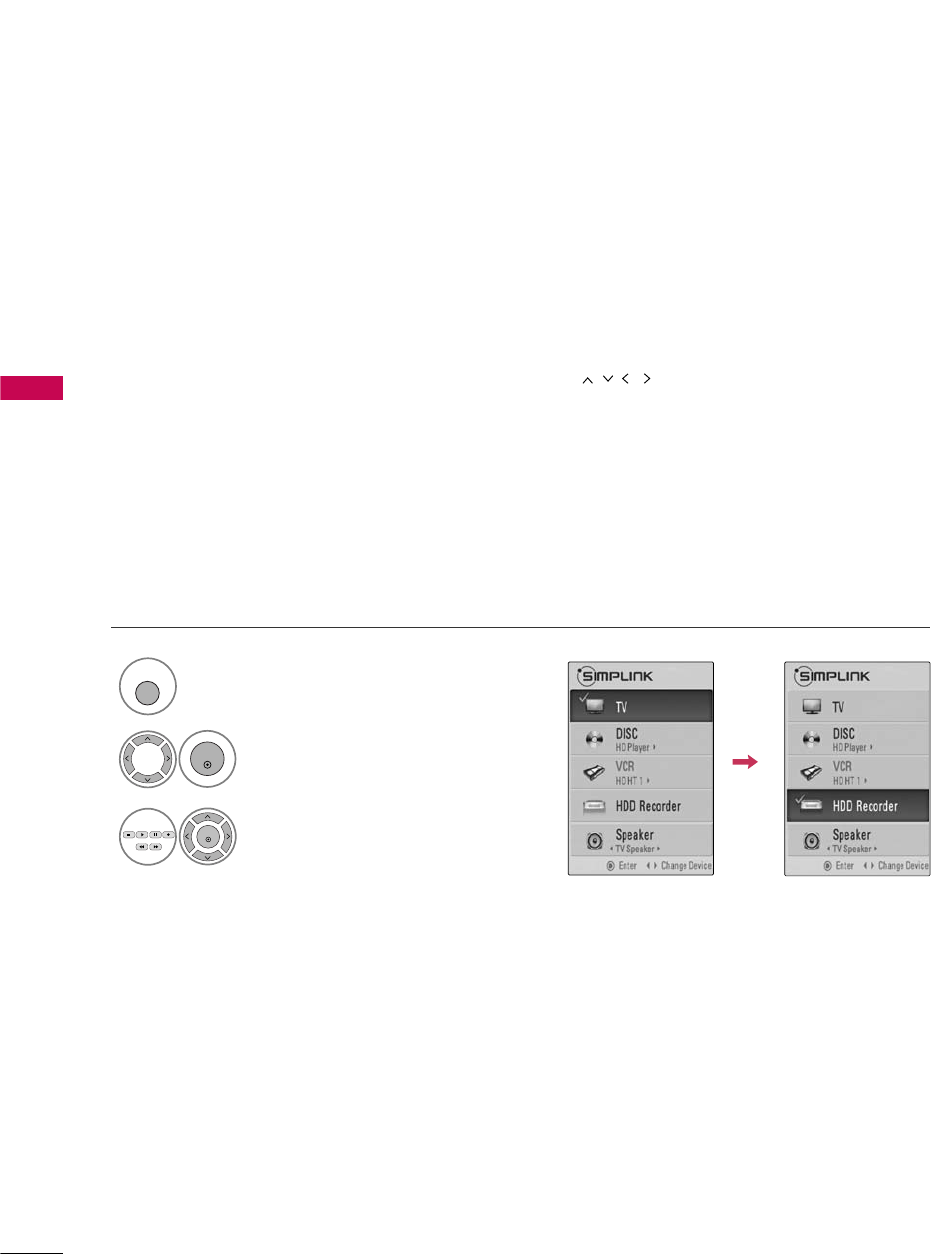
SIMPLINK Functions
Display SIMPLINK menu.
Select the desired device.
Control connected AV devices.
1
SIMPLINK
3
2
ENTER
ENTER
WATCHING TV / CHANNEL CONTROL
43
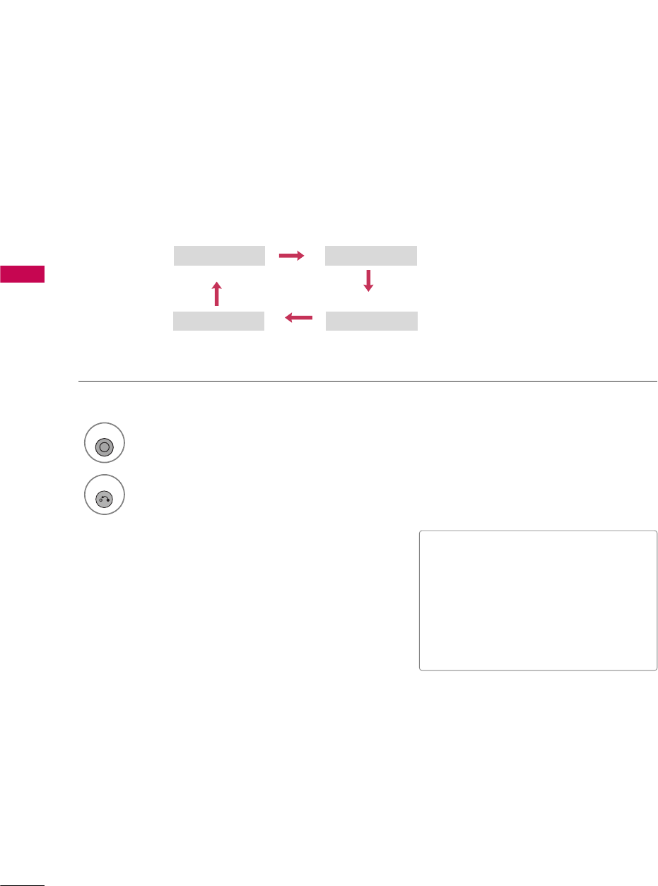
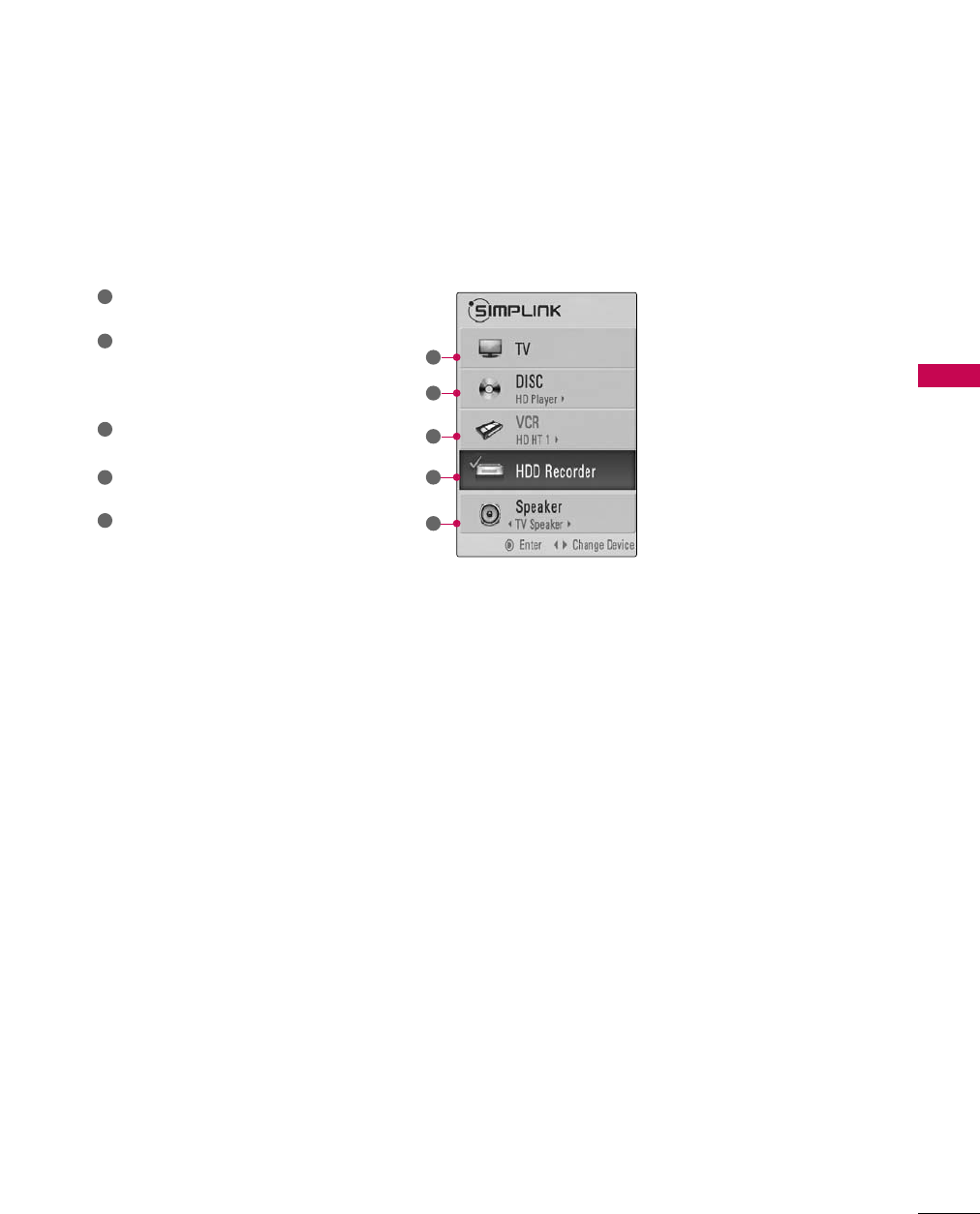
SIMPLINK Menu
TV vviewing: Switch to the previous TV
channel regardless of the current mode.
DISC pplayback: Select and play discs.
When multiple discs are available, the titles
of discs are conveniently displayed at the
bottom of the screen.
VCR pplayback: Control the connected
VCR.
HDD RRecordings pplayback: Control
recordings stored in HDD.
Audio OOut tto HHome TTheater sspeak-
er/Audio OOut tto TTV: Select Home
Theater speaker or TV speaker for Audio
Out.
1
2
3
4
5
G
When no device is connected
(displayed in gray)
G
Selected Device
G
When a device is connected
(displayed in bright color)
1
2
3
4
5
PICTURE CONTROL
44
PICTURE SIZE (ASPECT RATIO) CONTROL
PICTURE CONTROL
This feature lets you choose the way an analog picture with a 4:3 aspect ratio is displayed on your TV.
■ RGB-PC input source use 4:3 or 16:9 aspect ratio.
NOTE
!
GIf a fixed image is displayed on the screen for a long time, the image could become imprinted on the
screen and remain visible.
This phenomenon is common to all manufacturers and is not covered by warranty. Although, after watch-
ing video that did not fill the screen, any after-image from the black bars will normally dissipate after a few
minutes.
1
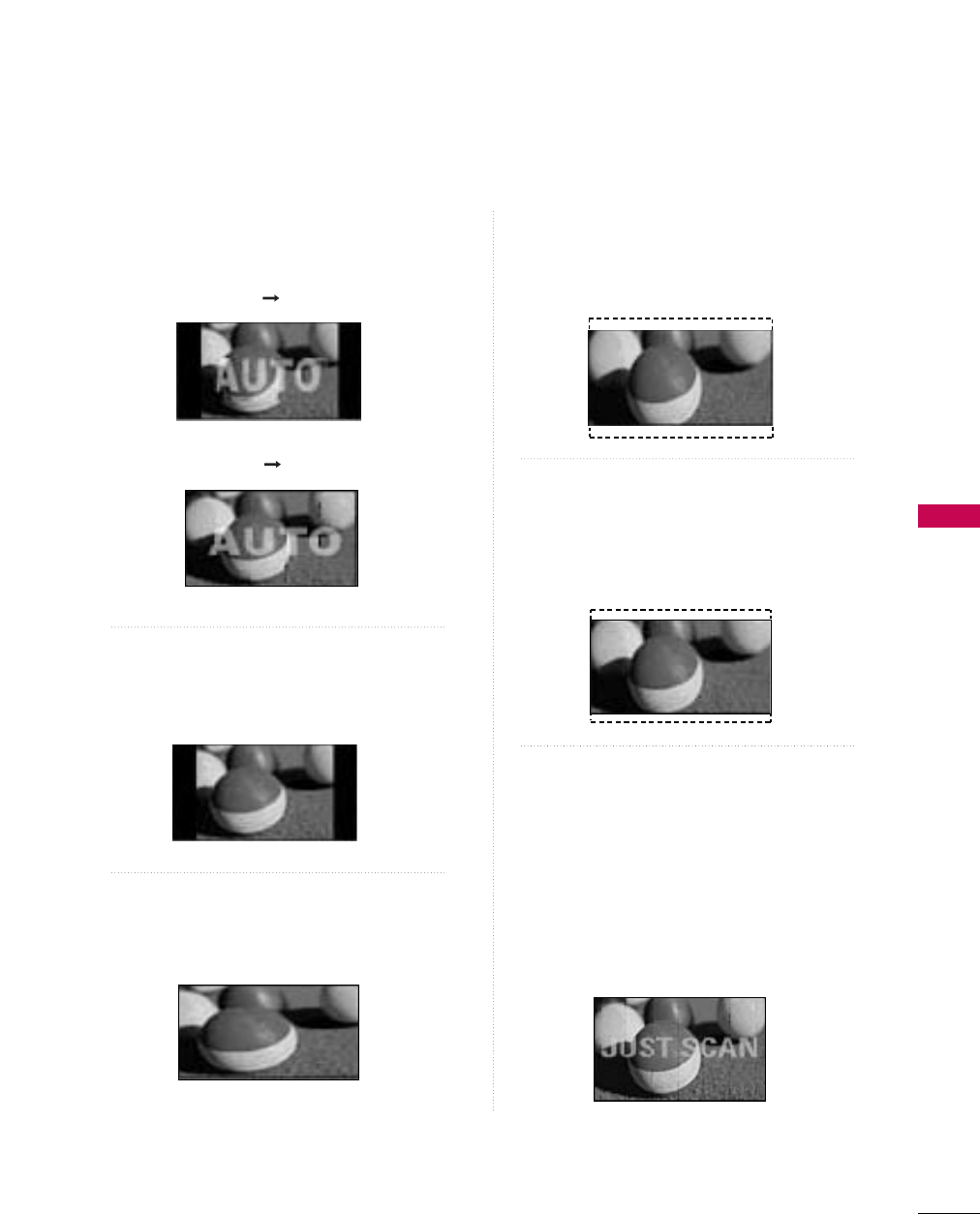
RATIO
Just Scan Zoom1
Zoom2
Set By Program
4:3 16:9
Select the desired picture format.
Q.Menu
Close
3
F16:9 G
Vivid
Off
Standard
Off
English
Off
Add
Aspect Ratio
Power Saving
Clear Voice
Picture Mode
Sound Mode
Caption
Multi Audio
Sleep Timer
Del/Add/Fav
CH
2
RETURN
Return to TV viewing.
PICTURE CONTROL
45
Set by program
Selects the proper picture proportion to match
the source’s image.
4:3
Choose 4:3 when you want to view a picture
with an original 4:3 aspect ratio.
16:9
Adjust the picture horizontally, in a linear pro-
portion to fill the entire screen.
Zoom 1
Choose Zoom 1 when you want to view the pic-
ture without any alteration. However, the top and
bottom portions of the picture will be cropped.
Zoom 2
Choose Zoom 2 when you want the picture to be
altered, both vertically extended and cropped.
The picture taking a halfway trade off between
alteration and screen coverage.
Just Scan
Following selection will lead to you view the pic-
ture of best quality without loss of original pic-
ture in high resolution image.
Notes: If there are noise in original picture, you
can see the noise at the edge.
Just SScan operates only in
DTV/CADTV/Component/HDMI-DTV/DVI-DTV
(720p/1080i/1080p) input source.
(4:3 4:3)
(16:9 16:9)
PICTURE CONTROL
46
PRESET PICTURE SETTINGS
PICTURE CONTROL
Picture Mode - Preset
There are factory presets for picture settings available in the user menus. You can use a preset, change each
setting manually.
■Vivid, Standard, Cinema, Sport,
Game, Expert1, or Expert2 Settings
are preset for the optimum picture quality
at the factory and are not adjustable.
1
PICTURE
Select Vivid,Standard, Cinema,
Sport, Game, Expert1, or Expert2.
2
RETURN
Return to TV viewing.
Q.Menu
Close
3
16:9
FVivid G
Off
Standard
Off
English
Off
Add
Aspect Ratio
Power Saving
Clear Voice
Picture Mode
Sound Mode
Caption
Multi Audio
Sleep Timer
Del/Add/Fav
CH
Vivid Standard
Expert1
Expert2
Game Sport
Cinema
PICTURE CONTROL
47
Color Tone - Preset
Choose one of three automatic color adjustments. Set to warm to enhance hotter colors such as red, or set to
cool to see less intense colors with more blue.
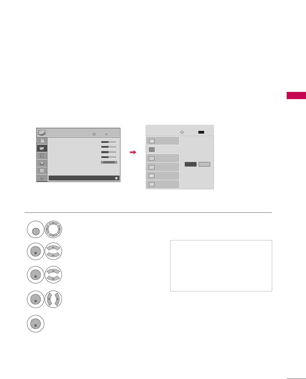
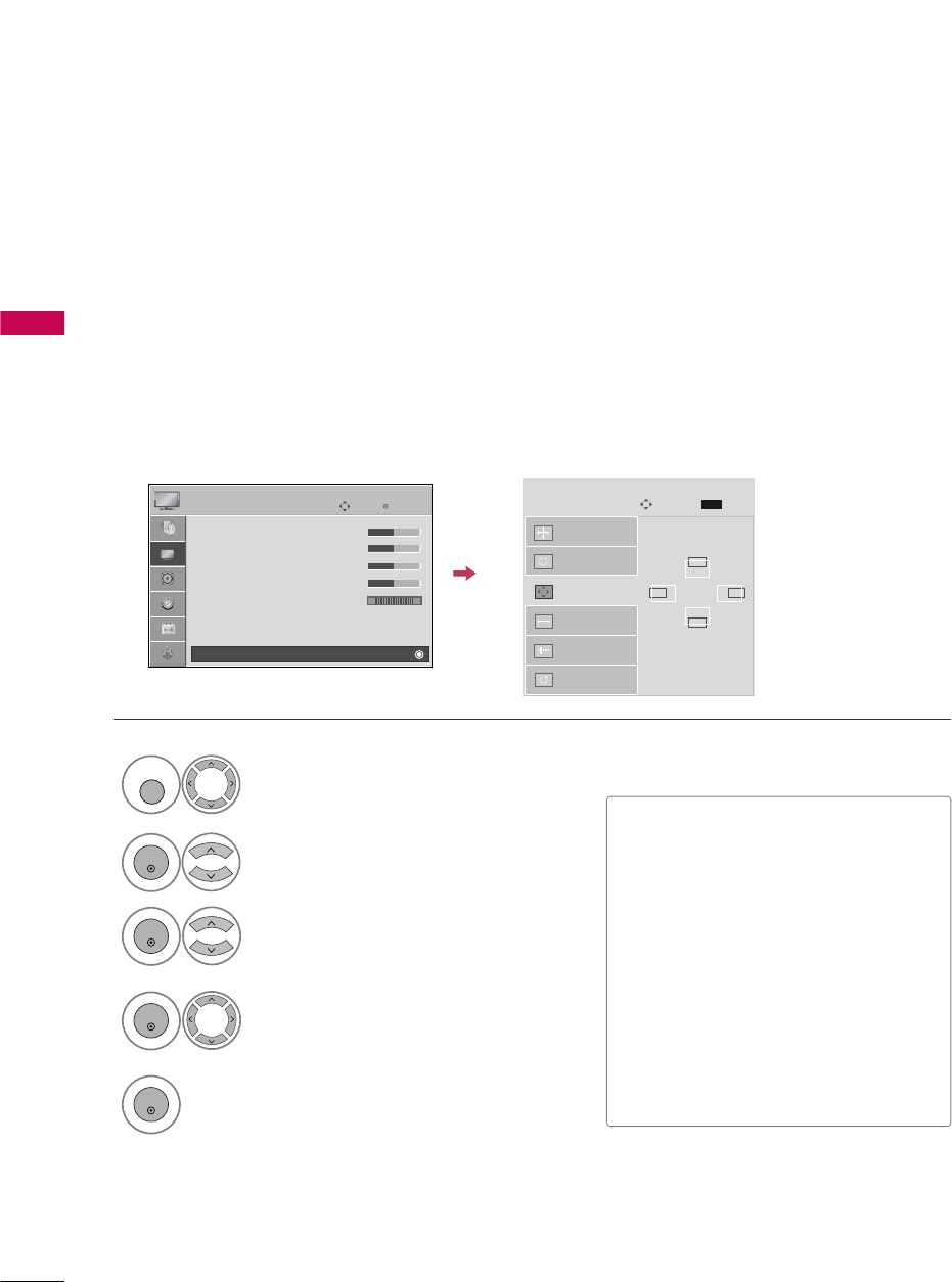
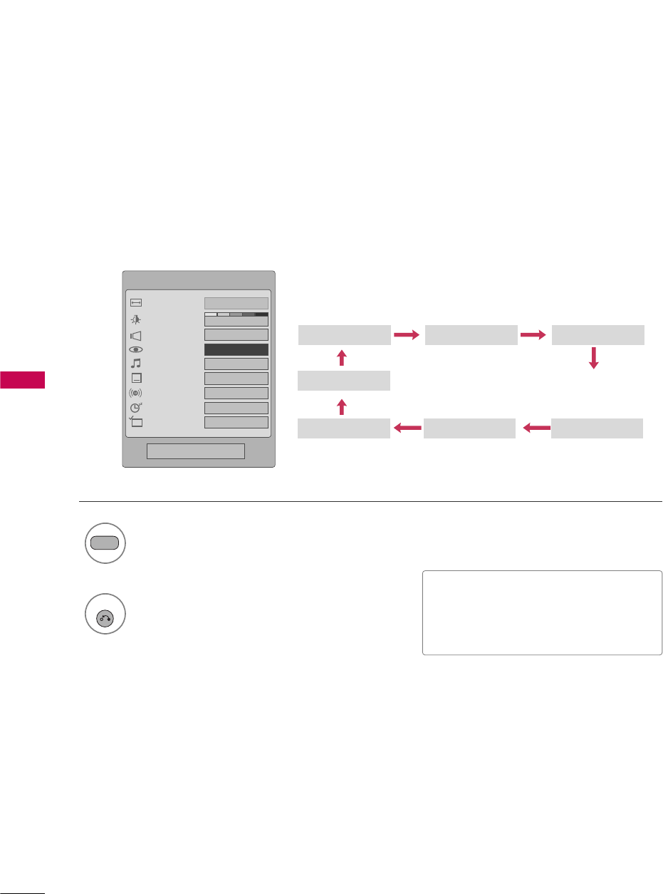
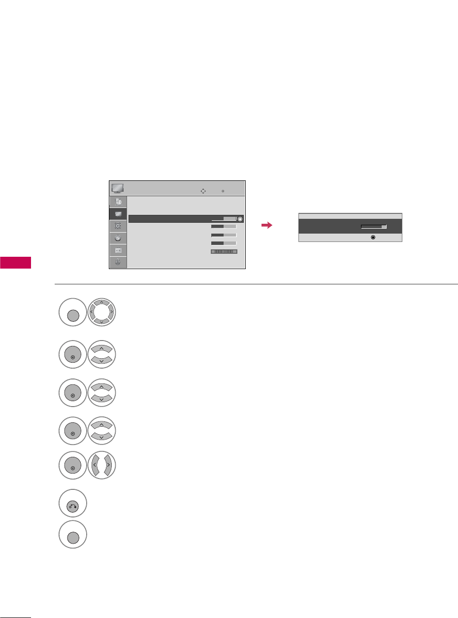
Select PICTURE.
Select Color TTemperature.
1
MENU
3
ENTER
Select Cool, Medium, or W arm.
4
Select Advanced CControl.
2
ENTER
5
RETURN
Return to the previous menu.
MENU
Return to TV viewing.
Enter
Move
PICTURE
E
RG
• Contrast 50
• Brightness 50
• Sharpness 50
• Color 50
• Tint 0
• Advanced Control
• Reset
Screen (RGB-PC)
Enter
Move
PICTURE
E
RG
• Contrast 50
• Brightness 50
• Sharpness 50
• Color 50
• Tint 0
• Advanced Control
• Reset
Screen (RGB-PC)
Color Temperature
FMedium G
Fresh Contrast
Off
Fresh Color
Off
Noise Reduction
Auto
Gamma
Medium
Black Level
Low
Film Mode
Off
Close
PICTURE CONTROL
48
MANUAL PICTURE ADJUSTMENT
PICTURE CONTROL
Picture Mode - User Mode
Adjust the picture appearance to suit your preference and viewing situations.
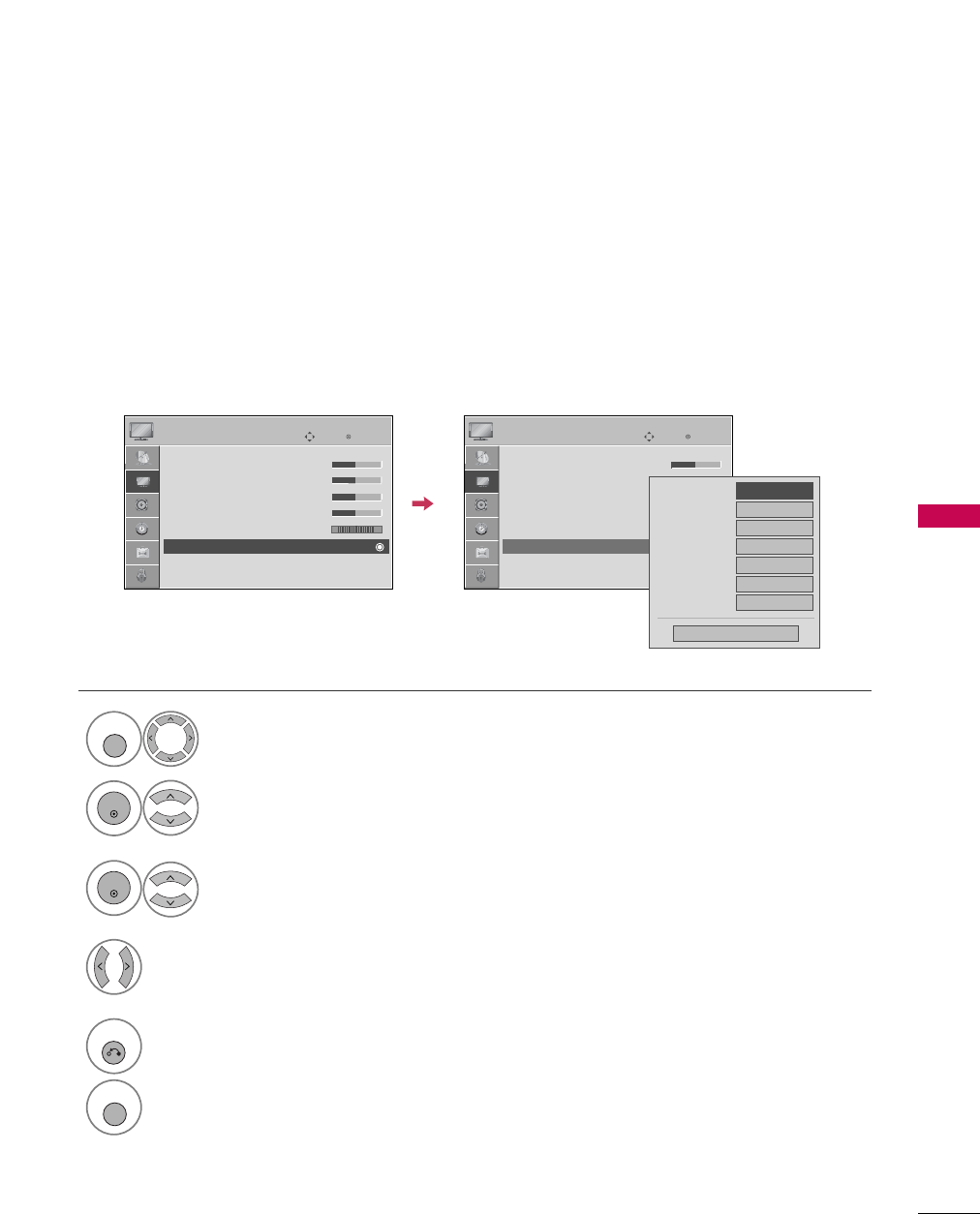
Select PICTURE.
Make appropriate adjustments.
Select Contrast, Brightness, Sharpness,
Color, or Tint.
1
MENU
Select Picture MMode.
2
ENTER
Select Vivid,Standard, Cinema, Sport, or Game.
3
ENTER
4
ENTER
5
ENTER
6
RETURN
Return to the previous menu.
MENU
Return to TV viewing.
Enter
Move
PICTURE
E
Aspect Ratio : 16:9
Picture Mode : Standard
• Contrast 90
• Brightness 50
• Sharpness 60
• Color 60
• Tint 0
• Advanced Control
• Contrast 80
E
E
E
E
Enter
RG