LG Electronics USA PWFMDB000 Internet Bridge User Manual MFL67940704
LG Electronics USA Internet Bridge MFL67940704
UserManual.wiki
>
LG Electronics USA
>
PWFMDB000 User Manual
Users Manual
Navigation menu
Upload a User Manual
Namespaces
Wiki Guide
HTML
PDF
Info
Views
User Manual
Discussion / Help
Navigation

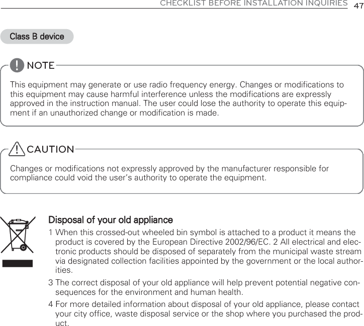
![INTERNET BRIDGE SETTING 277When you click the corresponding screen, the following program is automatically installed.• Java installation If the following page appears, install Javafollowing the figures. Note : Program installation If the JAVA program usually is not installed, you can install it manually by downloading fromthe website of JAVA (http://www.java.com).[Recommended: JAVA6]• Click ‘Here’. • Click ‘Run’. • Click ‘Agree and Start Free Download’. • Click ‘Installation’ to install.](https://usermanual.wiki/LG-Electronics-USA/PWFMDB000/User-Guide-2290751-Page-27.png)
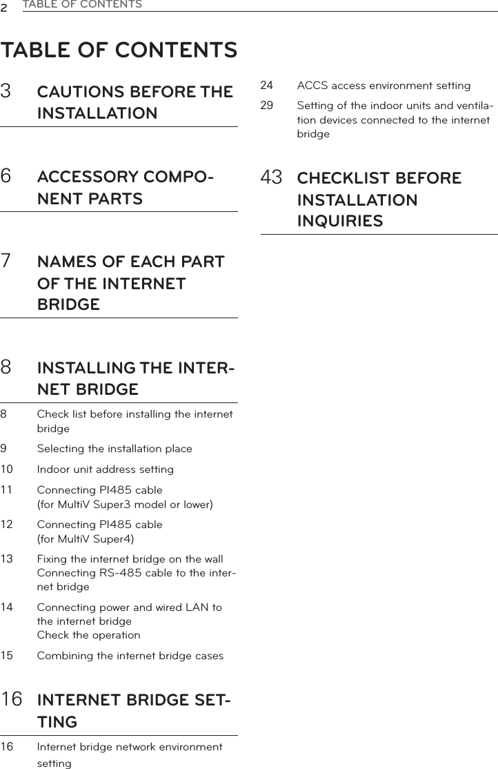
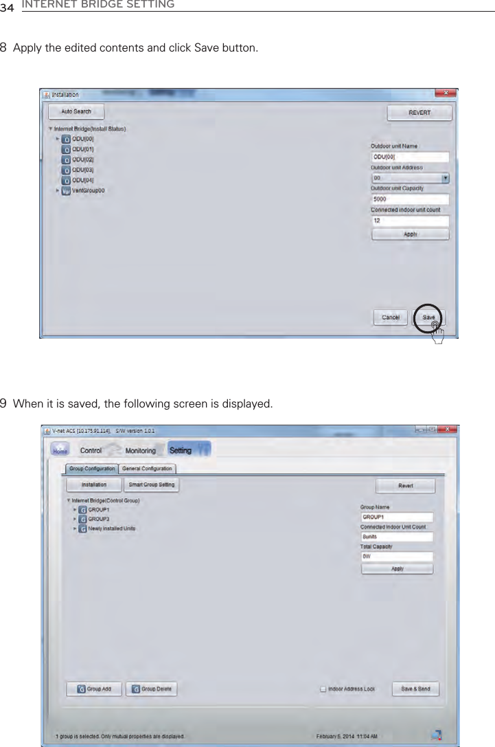
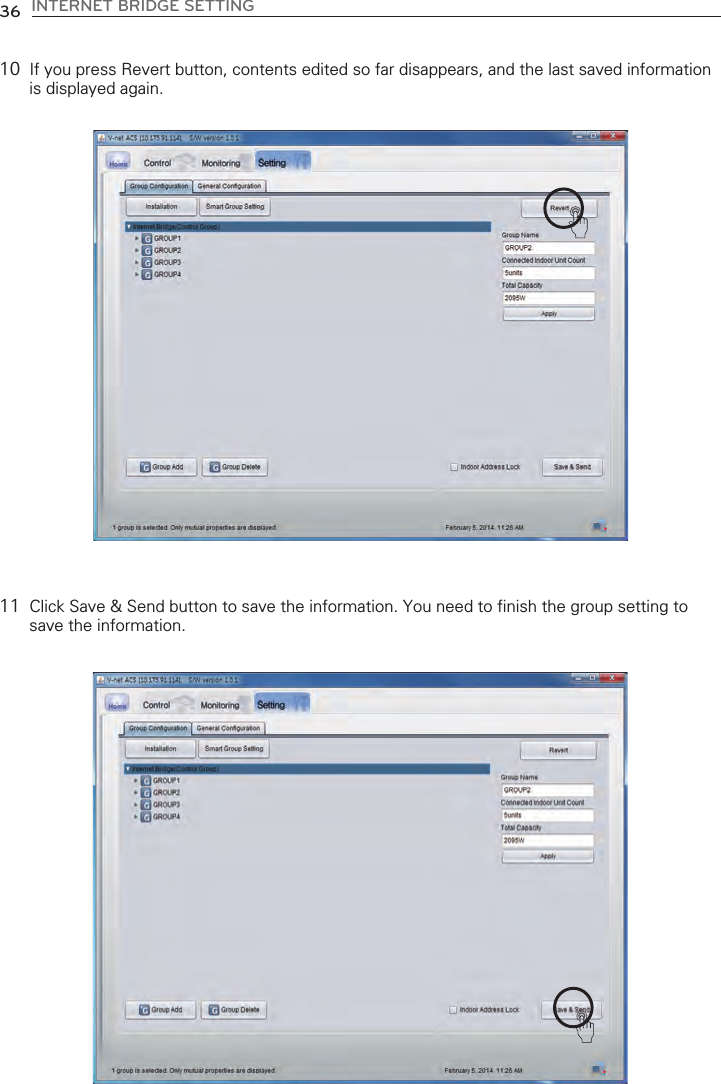
![INTERNET BRIDGE SETTING 337When the search is completed, indoor units/outdoor units list for each group is displayed. Change outdoor unit information You can change the outdoor unit name, central controladdress, outdoor unit capacity, and the number of the con-nected indoor units. After changing the information, you mustpress [Apply] button. When you change the number of theconnected indoor units, if you input a number smaller than thenumber of the previously connected indoor units, it deletesfrom the last input indoor unit, and if you input a numbergreater than the number of the previously connected indoorunits, it asks the first address of the indoor unit to add, andfrom the input address, it finds an empty address and addsthe indoor units as many as the number of the indoor units toadd sequentially.Change indoor unit informationYou can change the indoor unit name, central control address,and the indoor unit capacity. After changing the information,you must press [Apply] button.](https://usermanual.wiki/LG-Electronics-USA/PWFMDB000/User-Guide-2290751-Page-33.png)
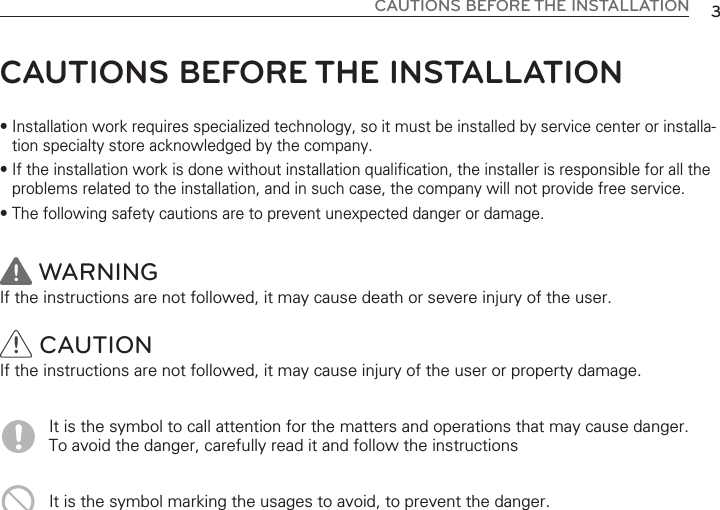
![INTERNET BRIDGE SETTING 35Automatic creation of the control groupMoving indoor unitIf you press [Smart Group Setting] button, the control group isautomatically created based on the outdoor unit and ventila-tion group information input in the installation status.You can select an indoor unit and move to another outdoor unit. When you move an indoor unit,click an indoor unit with mouse, drag it and put it on another outdoor unit.](https://usermanual.wiki/LG-Electronics-USA/PWFMDB000/User-Guide-2290751-Page-35.png)
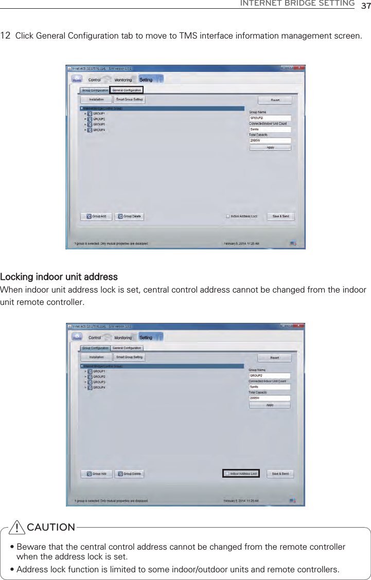
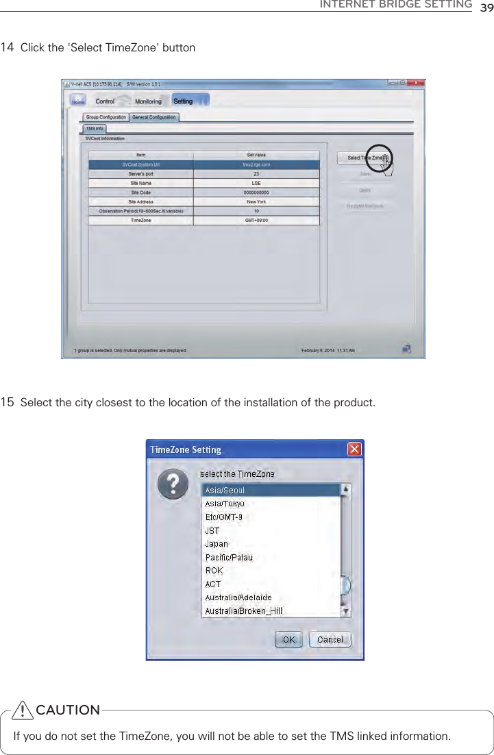
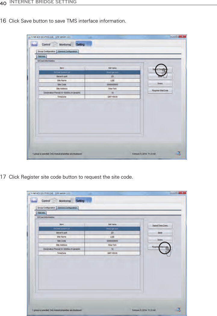
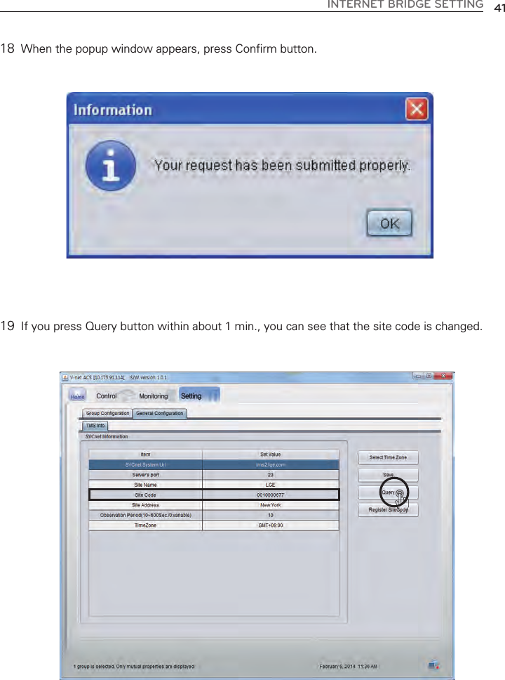
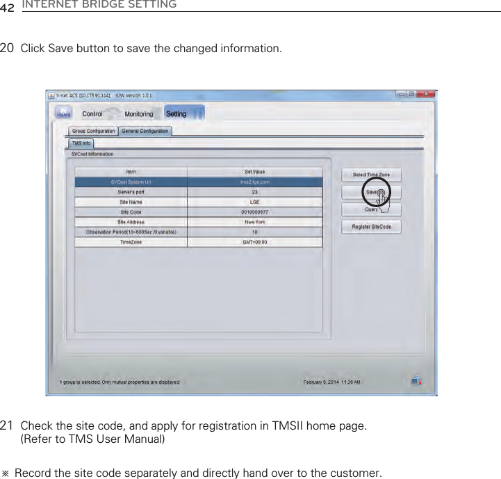
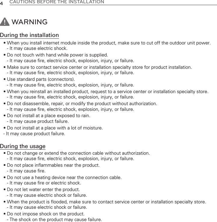
![13 Modify each category except the site code by referring to the next page’s TMS interfaceinformation. ڸڹںڻڼڽ38 INTERNET BRIDGE SETTINGNote : TMS interface information TMS interface information to input are as follows Category Description ①Management system address Input TMS system internet address (http://tms2.lge.com). ③Site name Input the site name. ⑤Site address Input the site address. ※You can search the address in http://maps.google.co.kr. Input the address searched from the above site. ⑥Monitoring period Input the monitoring period in the units of seconds. (Minimum monitoring period is 10 seconds) ⑦Time Zone Settings Press the button [Select TimeZone] on the right side, and then enter the information of the city closest to the site. Site code is unique for each site. ④Site code If you press [Request site code] button on the right side, the online request for site code registration is submitted, and if you press [View] button within about 1 min., you can check the issued site code. ②Connection PORT number Input TMS system communication port number. (Select one from 21 or 23) CAUTIONSaveWhen the contents of the table are changed, you must press [Save] button to save thechanged information. TMS interface information Information related to TMS interface must be handled by an installation technician with instal-lation qualifications. Even if you input the above information, you may not be able use TMSinterface right away. If you have inquiries or questions related to the above, please contactservice center or installation specialty store acknowledged by the company.Time Zone SettingsIf you do not set the time zone, you will not be able to set the TMS linked information.In countries where the application of the daylight saving, please use it to check the time.!](https://usermanual.wiki/LG-Electronics-USA/PWFMDB000/User-Guide-2290751-Page-38.png)