LG Electronics USA PWFMDB000 Internet Bridge User Manual MFL67940704
LG Electronics USA Internet Bridge MFL67940704
Users Manual

P/NO : MFL67940704 www.lg.com
INSTALLATION/USER MANUAL
• Make sure to read the cautions for safety before installation and use, and use
it correctly.
• It is intended to keep protect the safety of the installer and user and to
prevent the property damage, etc.
• After reading the user manual, please keep it at a place where user can
access any time.
TYPE : Internet Bridge
MODEL : PWFMDB000

TABLE OF CONTENTS
2
3CAUTIONS BEFORE THE
INSTALLATION
6ACCESSORY COMPO-
NENT PARTS
7NAMES OF EACH PART
OF THE INTERNET
BRIDGE
8INSTALLING THE INTER-
NET BRIDGE
8Check list before installing the internet
bridge
9Selecting the installation place
10 Indoor unit address setting
11 Connecting PI485 cable
(for MultiV Super3 model or lower)
12 Connecting PI485 cable
(for MultiV Super4)
13 Fixing the internet bridge on the wall
Connecting RS-485 cable to the inter-
net bridge
14 Connecting power and wired LAN to
the internet bridge
Check the operation
15 Combining the internet bridge cases
16 INTERNET BRIDGE SET-
TING
16 Internet bridge network environment
setting
24 ACCS access environment setting
29 Setting of the indoor units and ventila-
tion devices connected to the internet
bridge
43 CHECKLIST BEFORE
INSTALLATION
INQUIRIES
TABLE OF CONTENTS

3
CAUTIONS BEFORE THE INSTALLATION
CAUTIONS BEFORE THE INSTALLATION
• Installation work requires specialized technology, so it must be installed by service center or installa-
tion specialty store acknowledged by the company.
• If the installation work is done without installation qualification, the installer is responsible for all the
problems related to the installation, and in such case, the company will not provide free service.
• The following safety cautions are to prevent unexpected danger or damage.
WARNING
If the instructions are not followed, it may cause death or severe injury of the user.
CAUTION
If the instructions are not followed, it may cause injury of the user or property damage.
It is the symbol to call attention for the matters and operations that may cause danger.
To avoid the danger, carefully read it and follow the instructions
It is the symbol marking the usages to avoid, to prevent the danger.
!
!

4CAUTIONS BEFORE THE INSTALLATION
WARNING
During the installation
• When you install internet module inside the product, make sure to cut off the outdoor unit power.
- It may cause electric shock.
• Do not touch with hand while power is supplied.
- It may cause fire, electric shock, explosion, injury, or failure.
• Make sure to contact service center or installation specialty store for product installation.
- It may cause fire, electric shock, explosion, injury, or failure.
• Use standard parts (connectors).
- It may cause fire, electric shock, explosion, injury, or failure.
• When you reinstall an installed product, request to a service center or installation specialty store.
- It may cause fire, electric shock, explosion, injury, or failure.
• Do not disassemble, repair, or modify the product without authorization.
- It may cause fire, electric shock, explosion, injury, or failure.
• Do not install at a place exposed to rain.
- It may cause product failure.
• Do not install at a place with a lot of moisture.
- It may cause product failure.
During the usage
• Do not change or extend the connection cable without authorization.
- It may cause fire, electric shock, explosion, injury, or failure.
• Do not place inflammables near the product.
- It may cause fire.
• Do not use a heating device near the connection cable.
- It may cause fire or electric shock.
• Do not let water enter the product.
- It may cause electric shock or failure.
• When the product is flooded, make sure to contact service center or installation specialty store.
- It may cause electric shock or failure.
• Do not impose shock on the product.
- The shock on the product may cause failure.
!

CAUTIONS BEFORE THE INSTALLATION 5
WARNING
• Firmly install on a place that can endure the weight of the internet bridge.
- If the installation place is not strong enough, the internet bridge may fall and break.
• Do not use the product in the following environments.
- If the product is used in a place with oil, steam, or sulfuric acid gas, it may cause performance
degradation or product damage.
• Do not press switch or button with a sharp object.
- It may cause electric shock accident or product failure.
• Check the operation temperature.
- If it is used in an environment exceeding the operation temperature range, it may cause a severe
damage. Check the usage temperature range specified in the manual. If there is no specified tem-
perature, use in the range of 0~40˚C.
• Make sure to request electric work to the specialty store where you purchased the product or serv-
ice center.
- It may cause fire or electric shock.
• Do not damage, process, or force to bend the power cord for usage.
- Do not place a container with water, etc. on the product.
• Do not place a container with water, etc. on the product.
- It may cause fire or electric shock.
• Do not connect the power cable to the control signal cable connector.
- It may cause fire or explosion.
• Do not touch the switch with wet hand.
- It may cause electric shock accident or product failure.
• For the connection with PC or peripheral devices, read the installation and user manual.
- Incorrect connection may cause a fire or product failure.
• If a warning window appears on PC and if the device stops or does not work, immediately stop
using the product.
- It may cause fire or product failure.
!
ACCESSORY COMPONENT PARTS
6
ACCESSORY COMPONENT PARTS
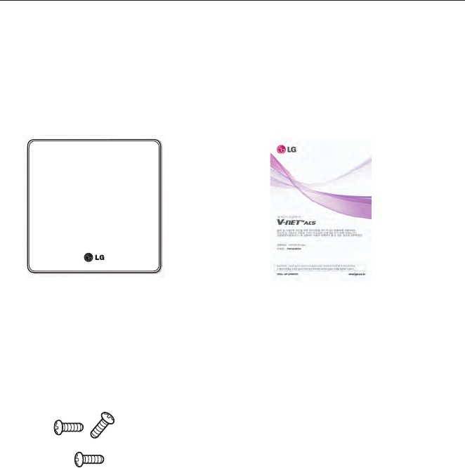
Internet Bridge Components
Open the packaging box of the internet bridge, and check if all the corresponding components
are enclosed.
Internet Bridge
Internet Bridge Internet bridge manual
Installation screw 3EA
7
NAMES OF EACH PART OF THE INTERNET BRIDGE
NAMES OF EACH PART OF THE INTERNET
BRIDGE
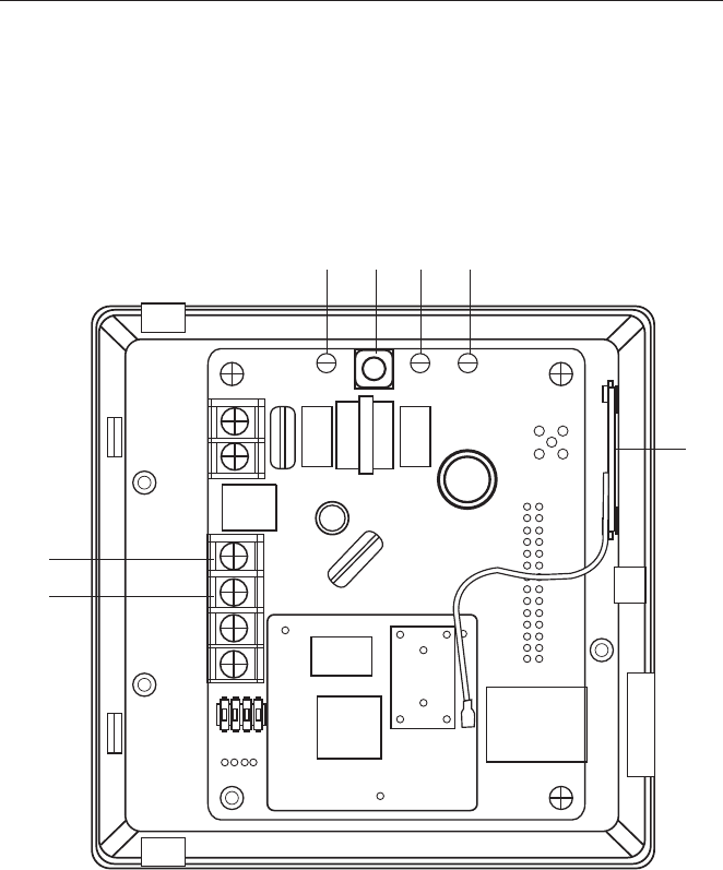
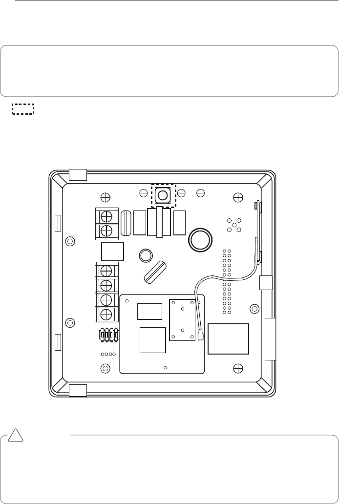
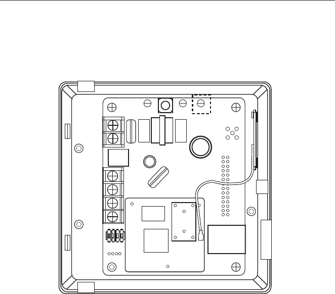
Names of each part of the internet bridge
It is the figure where PCB is installed inside the case, and the names of each part are as follows.
①
②③⑤④
⑥
⑦
①
Antenna
②
LED1
③
LED2
④
AP switch
⑤
Power LED
⑥
BUS-A
⑦
BUS-B
8INSTALLING THE INTERNET BRIDGE
INSTALLING THE INTERNET BRIDGE
Check list before installing the internet bridge
• When you configure the internet bridge network, you can connect up to 16 outdoor units.
Internet bridge composes the network with RS-485, and up to 16 outdoor unit PI485s can be
connected. (But, you can connect up to 31 SINGLE / Ventilation PI485s.)
• Internet bridge can connect up to 16 indoor units or Ventilator.
• During the configuration of the internet bridge RS-485, check the polarity.
RS-485 is divided to BUS-A and BUS-B.
If the corresponding Port is switched, there will be no communication, so be careful.
(RS-485 communication line can be used up to 1Km.)
• Internet bridge can be connected to internet.
You need to request the internet bridge’s IP address, Gateway address, and Netmask to the
person in charge of the network in the corresponding site.
• Check if other installed central controllers are set as Slave mode.
Internet bridge only works as Master mode, and it cannot interface with in master mode cen-
tral controller.
• Power socket shall be near the internet bridge power connection part, and the corresponding
socket shall be easily accessed.
• SSID and password of wireless router supports only ASCII code.
• Internet bridge supports only wireless router that uses the signal of 2.4GHz band.
Mobile App Usage Environment
<Recommended Specification>
* According to the smart phones, some functions may not work or some screens may not be dis-
played properly.
* This app is optimized for the above recommended specifications, some actions can not in other
environments.
* This App may not work in Tablet.
Mobile App may be updated to improve usability / design or to reinforce the contents.
Platform android
OS 4.0.x(ICS), 4.1.x(JellyBean)
Resolution 480 x 320, 1280 x 720, 1280 x 768

9
INSTALLING THE INTERNET BRIDGE
Selecting the installation place
• When it is installed with wireless communication
Internet bridge shall be installed within 10m from AP.
Communication is possible up to obstacles made of concrete wall (thickness 10cm or less) or
wooden door (or window).
• When it is installed as wired cables
Connect wired LAN cable of 10m or less to the internet bridge.
Protect the exposed wired LAN cable with cable pipe.
• Power connection
Internet bridge shall be installed within 2m from the power socket.
Arrange and connect the power cable.
• RS485 cable
It shall be installed at a place where it is connected to RS485 connecting to the outdoor unit.
• Indoor installation
Internet bridge shall be installed indoor, not outdoor.
Do not install at a place exposed to rain or with a lot of moisture.
Do not store or use flammable gas or inflammables near the product.
10 INSTALLING THE INTERNET BRIDGE
Note : Indoor unit address setting completed site
- The site that already completed the indoor unit address does not require address setting
again.
Note : How to set the indoor unit’s central control address
- According to the indoor unit product or the type of the remote controller, the methods of
setting the central control address may be different, so refer to the indoor unit product or
wired remote controller manual for the address setting.
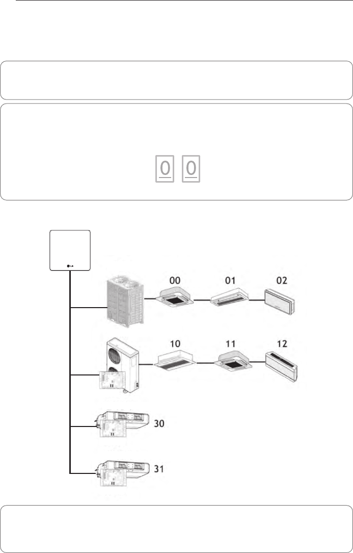
Note : Assignment of outdoor unit and indoor unit number
- If the outdoor unit product is Multi V, it is recommended to set the first digit of the address
with outdoor unit number, and set the second digit with indoor unit number, so that the sys-
tem composition and division can be easily identified during the address setting.
Indoor unit address setting
The addresses of the indoor units connected to one internet bridge shall be assigned without
overlapping. You can set the indoor unit address as hexadecimal 00 ~ FF.
The following is an example of assigning addresses to the indoor unit.
Outdoor unit (group) number Indoor unit number
i@b
Multi V
Multi V
Ventilation device
Ventilation device
PI485
PI485
PI485
10V GND
BUS_A BUS_B
INSTALLING THE INTERNET BRIDGE 11
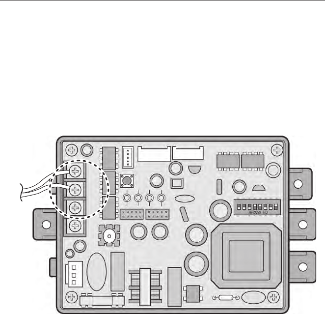
Connecting PI485 cable (for MultiV SuperIII model or lower)
When you install PI485, you need to set DIP switch.
(For DIP switch setting, refer to each PI485 manual.)
After installing PI485, connect RS-485 cable.
To connect PI485 and the internet bridge, two RS-485 cables shall be connected to PI485’s
BUS_A and BUS_B.
Refer to the following figure to connect RS-485 cable.
If several PI485’s are connected to the internet bridge, connect the cable’s BUS_A part to BUS_A
connector of each PI485, and connect cable’s BUS_B part to BUS_B connector of each PI485.
Outdoor unit connector
SODU
IDU CEN DRY1
----
DRY2 GND
BA BABA
12V
Outdoor unit connector
SODU
IDU CEN DRY1
----
DRY2 GND
BA BABA
12V
Outdoor unit connector
SODU
IDU CEN DRY1
----
DRY2 GND
BA BABA
12V
i@b
12 INSTALLING THE INTERNET BRIDGE
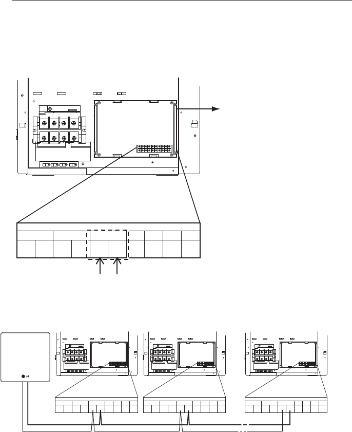
Connecting PI485 cable (for MultiV Super IV)
1Connect the central controller communication line (RS485 cable) to the central control connec-
tor (CEN_A, CEN_B) of the external board.
* It shall be connected according to the polarity between the wires.
2If you connect several outdoor units and the central controller, make sure to connect in the
form of a BUS.
Outdoor unit connector
SODU
IDU CEN DRY1
--- -
DRY2 GND
BA BABA
12V
External board
CEN_A
CEN_B
BUS-A
BUS-B
A
B
13
INSTALLING THE INTERNET BRIDGE
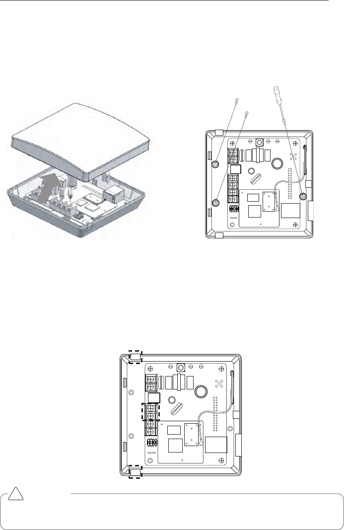
Fixing the internet bridge on the wall
Internet bridge can be installed on a wall.
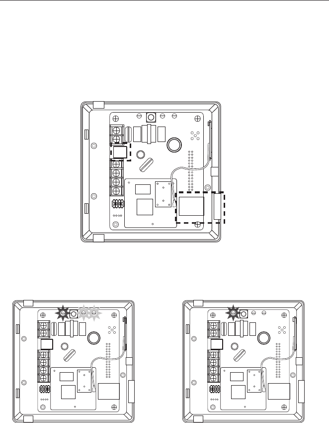
Connecting RS-485 cable to the internet bridge
You need to connect RS-485 cable to the internet bridge.
1Connect the end of RS-485 cable connected to BUS-A of PI485 to BUS-A part of the internet
bridge.
2Connect the end of RS-485 cable connected to BUS-B of PI485 to BUS-B part of the internet
bridge.
3Arrange the cables into A part or B part.
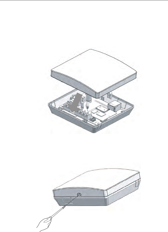
1Remove the screws on the right side to
open the case of the Internet bridge.
2Fix it on the wall using the enclosed screws
on the locations marked in the following fig-
ure.
CAUTION
During the use of B part, foreign objects may enter, so close the hole after arranging the
cable.
!
Power LED
Power LED
Power LED Power LED
Power LED
Power LEDLED2
LED2
LED2 LED1
LED1
LED1
A
B
14 INSTALLING THE INTERNET BRIDGE
Check the operation
Connecting power and wired LAN to the internet bridge
1If wired LAN is used, connect LAN cable to A part in advance, and when wireless LAN is used,
take a memo of the information (SSID, password, etc.) of AP to connect in advance.
2Internet bridge can work with DC 12V power. Connect to B part in the following figure.
1Apply power to the internet bridge.
(Check if power LED, LED1, LED2 are light-
ed)
2When the booting is completed, LED1 and
LED2 will be turned off.
Combining the internet bridge cases
Combine the cases after going through the internet bridge setting in the next page.
1When the network setting is completed, combine the cases.
2Connect the upper part and the lower part to each other.
3Fix the right side of the case with a screw.
15
INSTALLING THE INTERNET BRIDGE
AP switch
16 INTERNET BRIDGE SETTING
Internet bridge network environment setting
1Press the marked AP switch for 1~5 sec.
2When LED 2 blinks once, take off your finger from the switch.
3After 5 seconds, if LED 1 blinks with 1 second interval, move to the next step.
(If LED 2 does not blink, press the switch again for 1~5 sec.)
Note : Preparations before the internet bridge network setting
- For this step, LG Whisen system air conditioner App needs to be installed in the smart phone.
- LG Whisen system air conditioner App can be downloaded from Google Play Store, and refer
to the App manual for details.
CAUTION
Switch operation
- When the internet bridge AP switch is pressed for 5 seconds or longer, it is reset, so be
careful.
- When Green LED 1 blinks, if you press the internet bridge switch once again, it returns to
the operation mode.
!
INTERNET BRIDGE SETTING 17
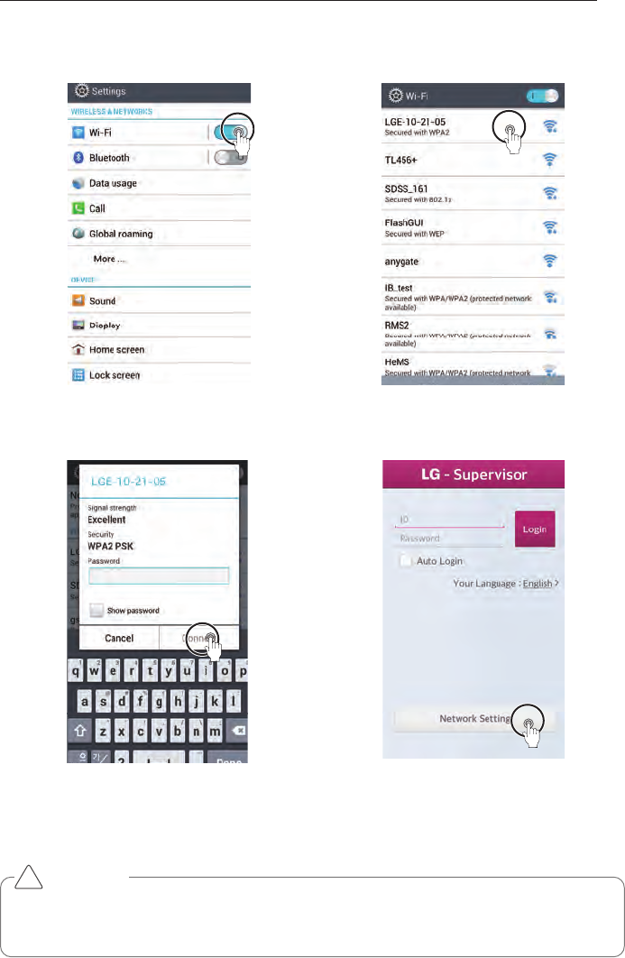
4Connect the internet bridge and the smart phone with wireless communication.
CAUTION
The network setting button appears only when the internet bridge and the smart phone is
connected with wireless connection.
!
Turn on Wi-Fi in the system
setting of the smart phone.
Select LGE-XX-XX-XX.
Input password and select
connection.
After running the system
air conditioner App, select
network setting button.
Password : digitalwifi
18 INTERNET BRIDGE SETTING
Wireless communication setting
1Select AP to connect to the internet bridge with wireless communication.
Note : Setting the wired communication
- To set wired communication for the internet bridge, refer to the wired communication setting
section.
Input the password, and
select log-in button.
Select the network set-
ting.
Select AP to connect. If it is an AP with security
setting, input password
and select Confirm button.
INTERNET BRIDGE SETTING 19
Note : AP information
You need to receive AP name (SSID) and password to use for the internet bridge from the
person in charge of the network in the corresponding site.
IP will be automatically assigned.
Note : The password
The LG System Air Conditioner Configuration password, please refer to the LG air condition-
ing system home page.
CAUTION
If the network setting is incorrectly input, there may be communication defect, or control
through the internet bridge may be impossible. Therefore, be careful and input correctly.
!
20 INTERNET BRIDGE SETTING
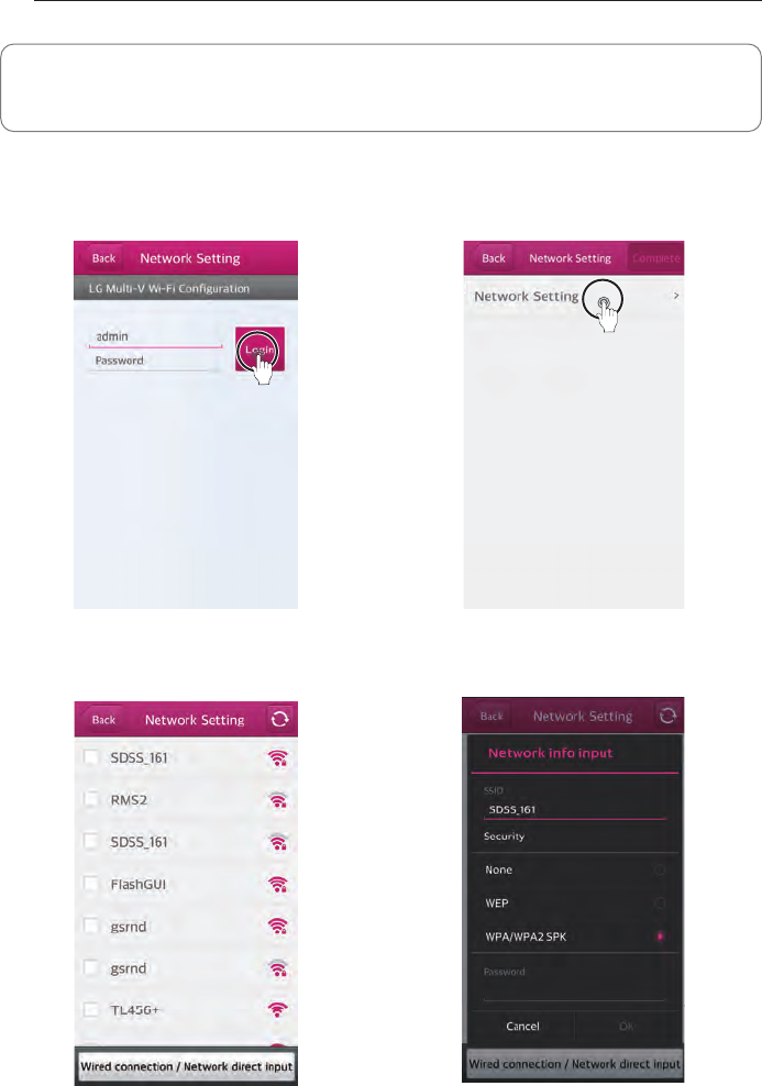
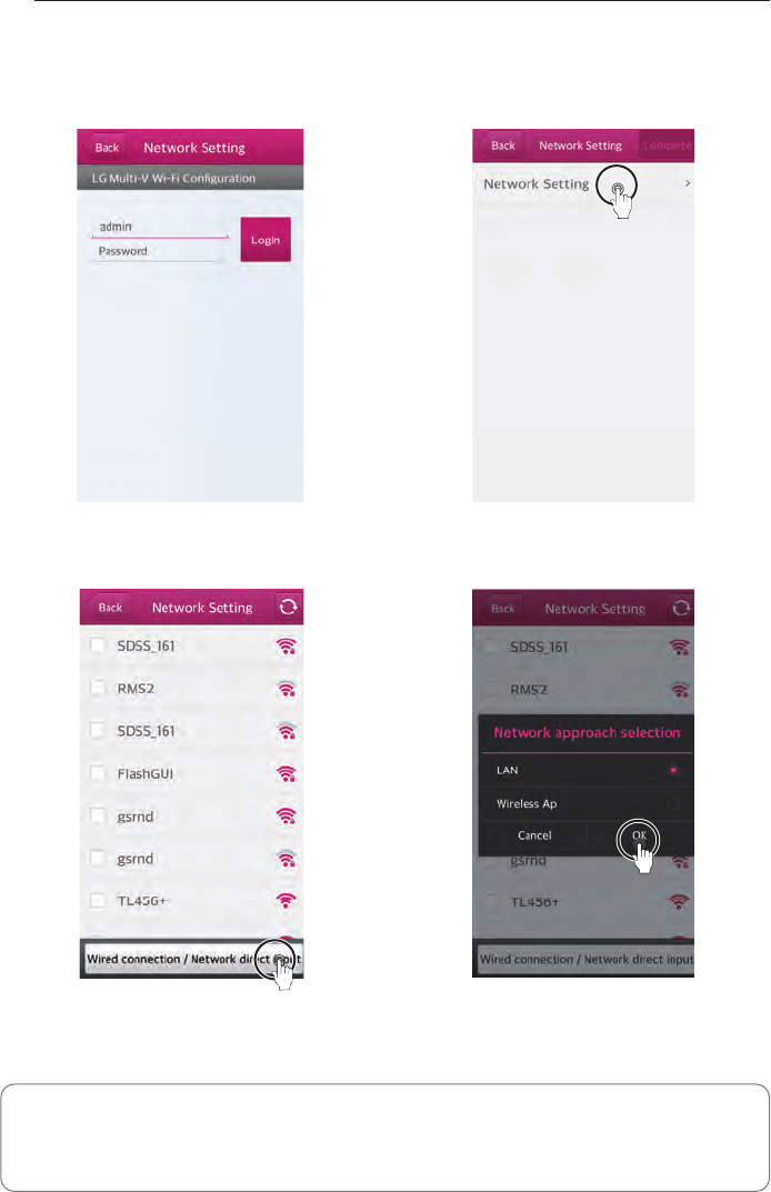
Wired communication setting
1Set the wired communication for the internet bridge.
Input the password, and
select log-in button.
Select network setting.
Press wired
connection/network direct
input.
Select LAN, and press
OK button.
Note : The password
The LG System Air Conditioner Configuration password, please refer to the LG air condition-
ing system home page.
INTERNET BRIDGE SETTING 21
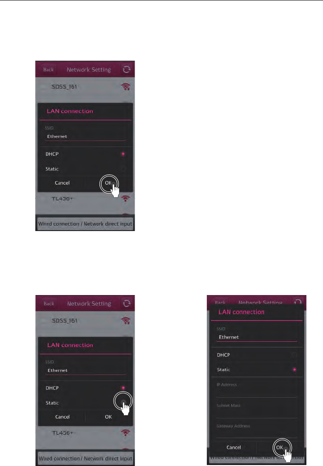
2Set the IP.
2-1 Set dynamic IP.
2-2 Set static IP.
Select DHCP and press
OK button.
Select Static. Input the network informa-
tion and select OK button.
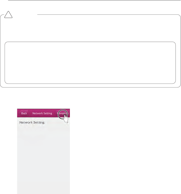
22 INTERNET BRIDGE SETTING
When you press Complete
button, the internet bridge
network setting is complet-
ed.
Note : Network address assignment
Internet bridge can use both the dynamic IP type and static IP type, but static IP type is
recommended, and if dynamic IP type is used, it may cause inconvenience of the user.
If static IP type is used, you need to receive the network addresses from <person in
charge of the network> in the corresponding site. (IP address, Gateway address,
Subnet mask)
CAUTION
For static IP setting, if the network settings (IP address, Gateway address, Subnet mask) are
incorrectly input, there may be communication defect or control through the internet bridge
may be impossible. Therefore, be careful and input correctly.
!
LED1
23
INTERNET BRIDGE SETTING
5When it is successfully set, LED 1 lamp continues to be lighted.
If LED 1 lamp is not turned on, run the internet bridge setting again.
24 INTERNET BRIDGE SETTING
ACCS access environment setting
It configures ACCS access environment setting.
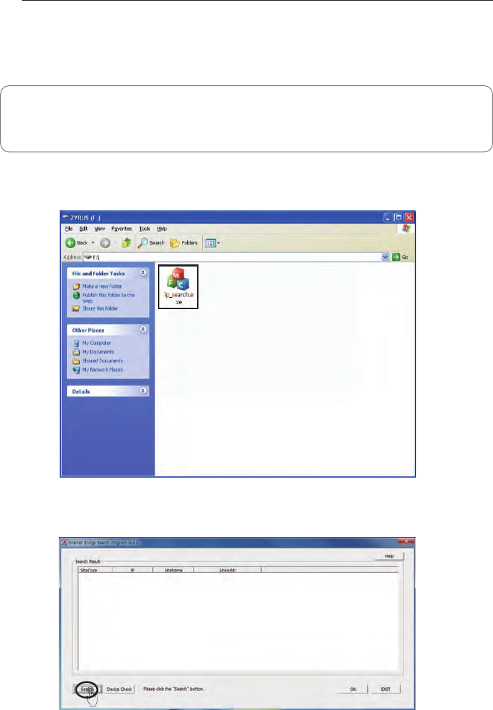
In PC environment, use IP_Search program to set ACCS access environment.
1Run Ip_search.exe
2Click search button to start the search for the internet bridge.
Note : IP_Search program
For information about installing IP_Search program, please refer to the LG Electronics air con-
ditioning system home page.
INTERNET BRIDGE SETTING 25
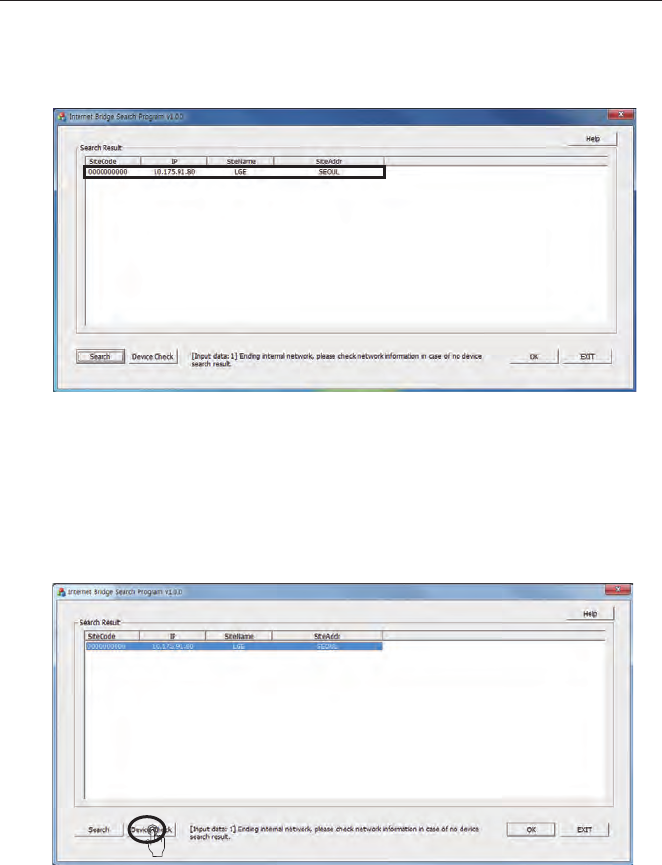
3When the search results are displayed, select the desired device.
4Select a device and click “Confirm Device” button, then you can see that LED 1 of the corre-
sponding internet bridge blinking 3 times with 1 second interval.
26 INTERNET BRIDGE SETTING
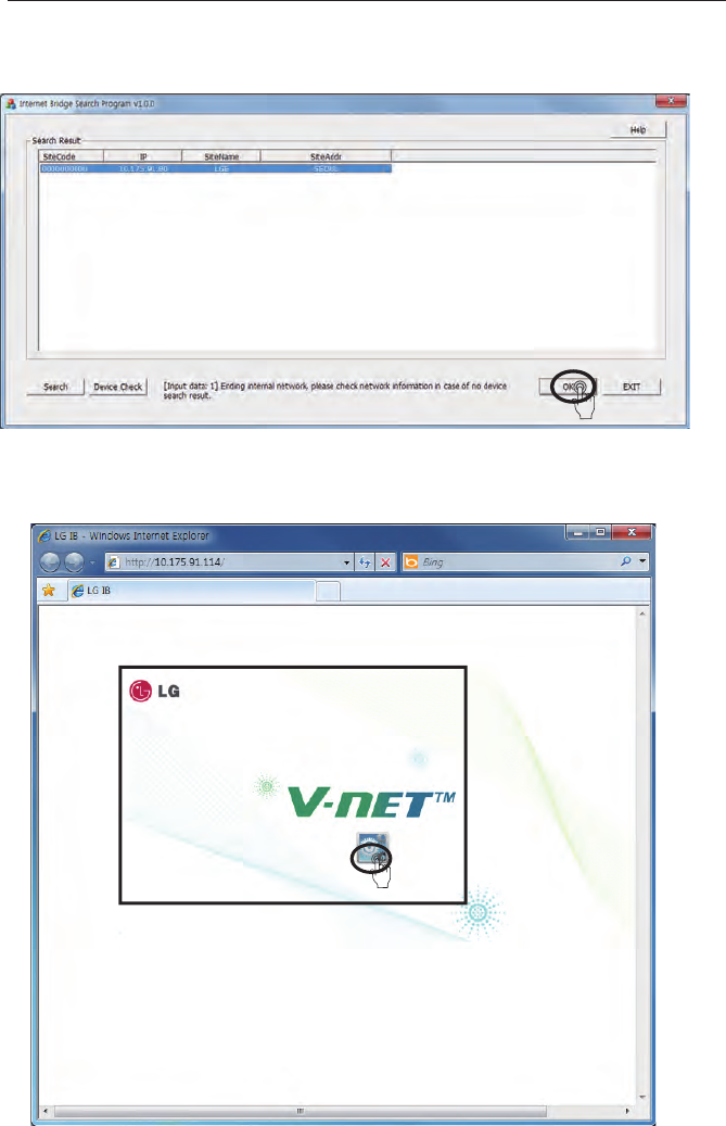
5When you completed the verification of the internet bridge, click OK button after the selection.
6When the web browser is launched and the screen is displayed as follows, click the corre-
sponding screen.
INTERNET BRIDGE SETTING 27
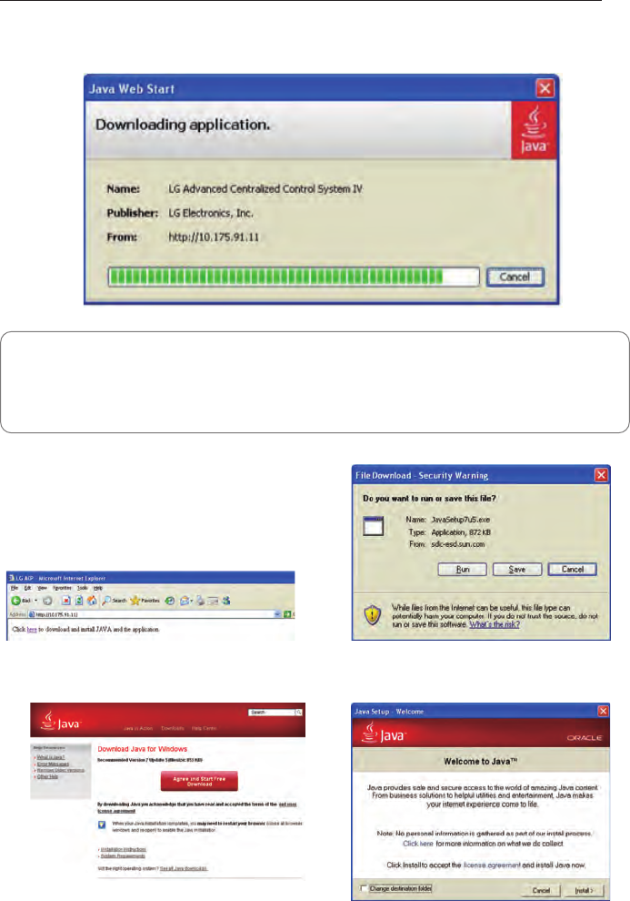
7When you click the corresponding screen, the following program is automatically installed.
• Java installation
If the following page appears, install Java
following the figures.
Note : Program installation
If the JAVA program usually is not installed, you can install it manually by downloading from
the website of JAVA (http://www.java.com).
[Recommended: JAVA6]
• Click ‘Here’. • Click ‘Run’.
• Click ‘Agree and Start Free Download’. • Click ‘Installation’ to install.
28 INTERNET BRIDGE SETTING
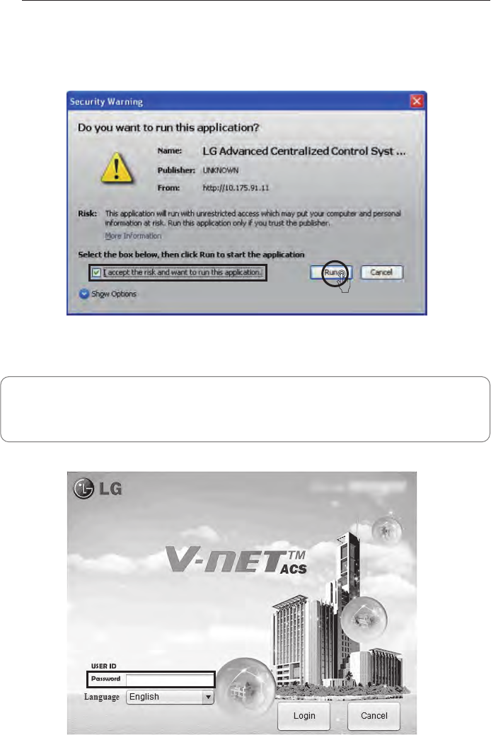
8If the program is installed, the following screen is displayed.
Select Check Box and click Run button.
9When the program is successfully installed, the following screen is displayed.
Note : Password
The corresponding program is a program for the installer.
Please refer to the LG system air conditioning website password.
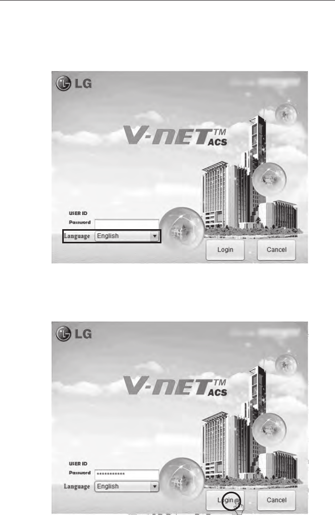
Setting of the indoor units and ventilation devices connected to
the internet bridge
1To the (Korean / English) and select the language.
2Input password and click Login button.
INTERNET BRIDGE SETTING 29
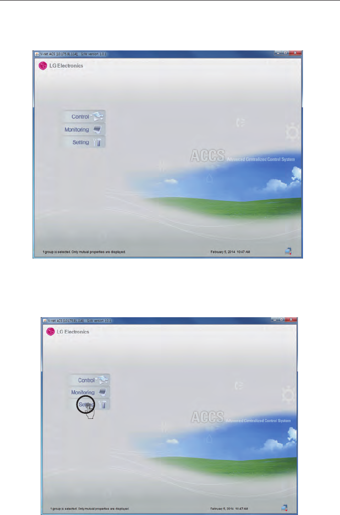
3When the program runs normally, the following screen is displayed.
4Click system setting menu.
30 INTERNET BRIDGE SETTING
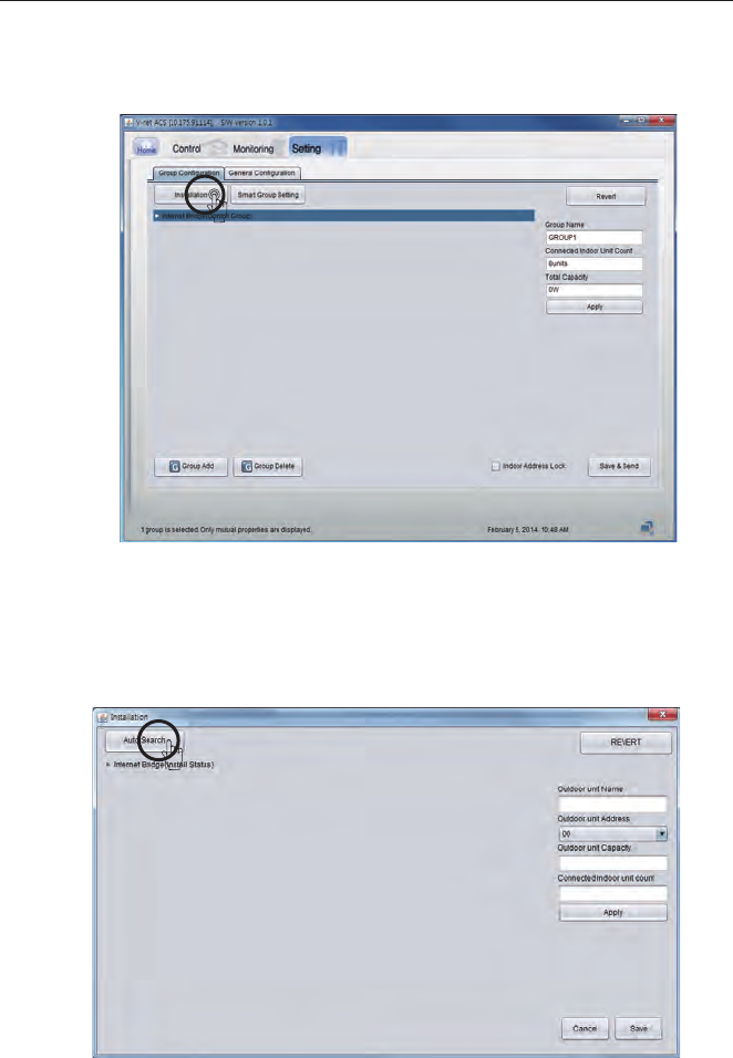
5Click the installation button.
6Select Auto search button at the top left corner.
INTERNET BRIDGE SETTING 31
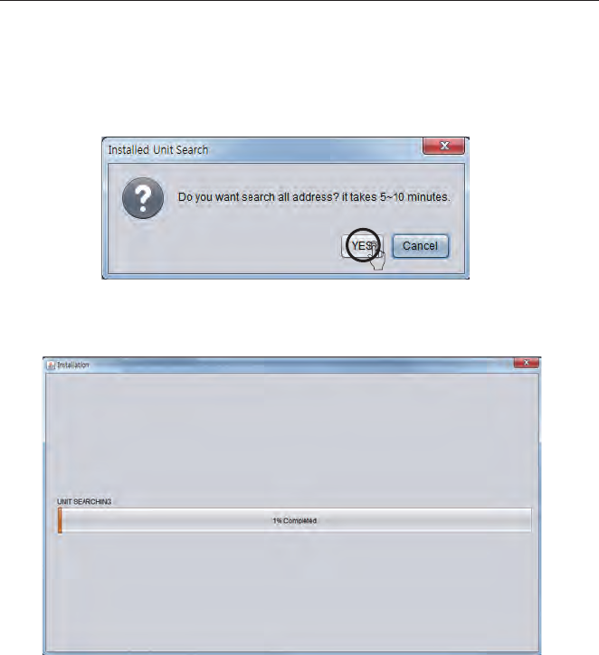
32 INTERNET BRIDGE SETTING
If automatic search button is pressed, it starts the search for the indoor units and ventilation
products that are connected to the internet bridge.
Automatic search takes about 5~10 min.
INTERNET BRIDGE SETTING 33
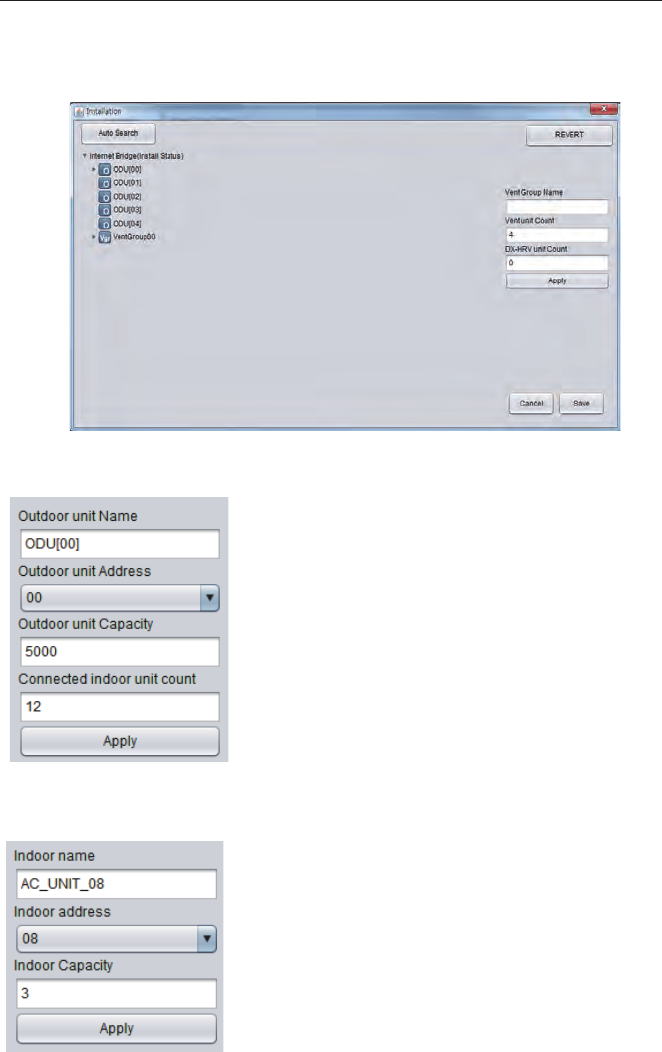
7When the search is completed, indoor units/outdoor units list for each group is displayed.
Change outdoor unit information
You can change the outdoor unit name, central control
address, outdoor unit capacity, and the number of the con-
nected indoor units. After changing the information, you must
press [Apply] button. When you change the number of the
connected indoor units, if you input a number smaller than the
number of the previously connected indoor units, it deletes
from the last input indoor unit, and if you input a number
greater than the number of the previously connected indoor
units, it asks the first address of the indoor unit to add, and
from the input address, it finds an empty address and adds
the indoor units as many as the number of the indoor units to
add sequentially.
Change indoor unit information
You can change the indoor unit name, central control address,
and the indoor unit capacity. After changing the information,
you must press [Apply] button.
34 INTERNET BRIDGE SETTING
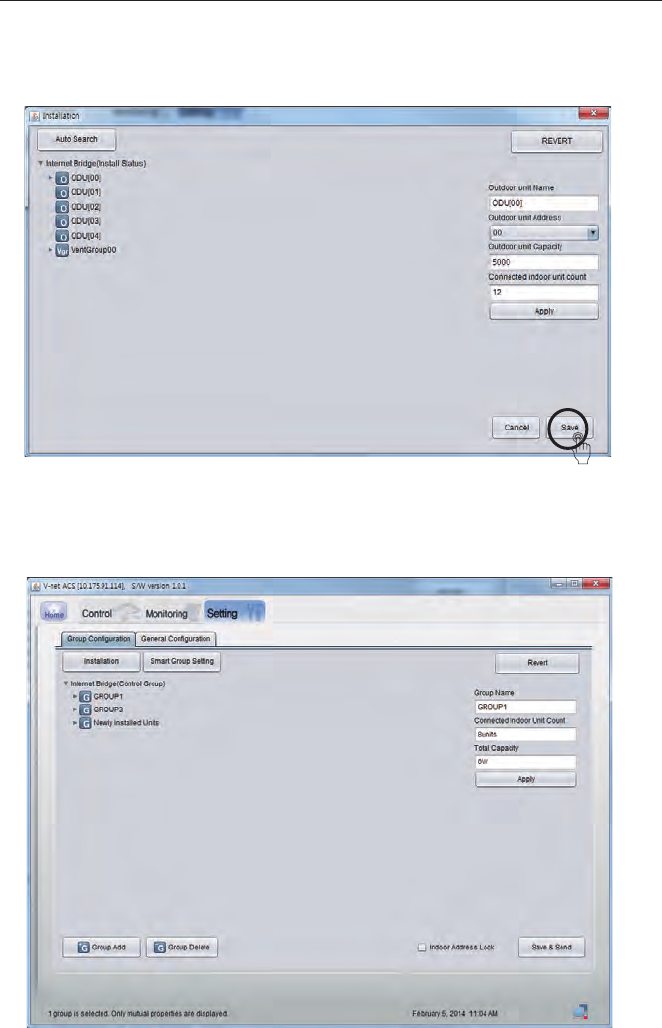
8Apply the edited contents and click Save button.
9When it is saved, the following screen is displayed.
INTERNET BRIDGE SETTING 35
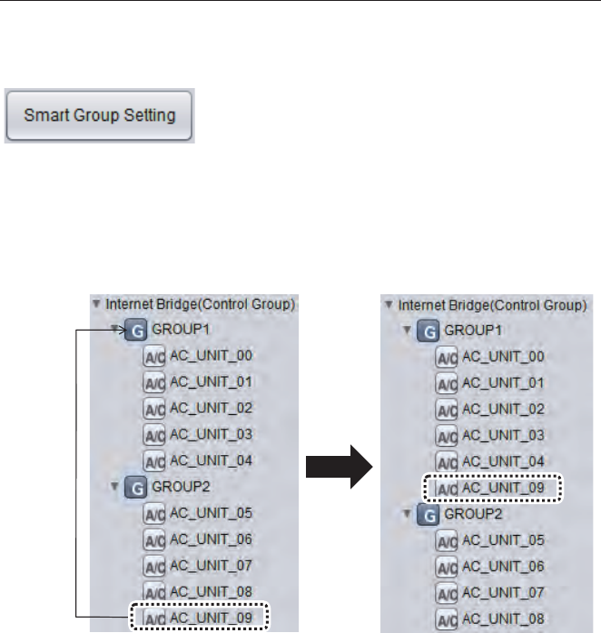
Automatic creation of the control group
Moving indoor unit
If you press [Smart Group Setting] button, the control group is
automatically created based on the outdoor unit and ventila-
tion group information input in the installation status.
You can select an indoor unit and move to another outdoor unit. When you move an indoor unit,
click an indoor unit with mouse, drag it and put it on another outdoor unit.
36 INTERNET BRIDGE SETTING
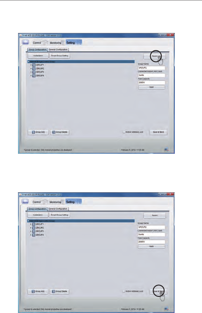
10 If you press Revert button, contents edited so far disappears, and the last saved information
is displayed again.
11 Click Save & Send button to save the information. You need to finish the group setting to
save the information.
INTERNET BRIDGE SETTING 37
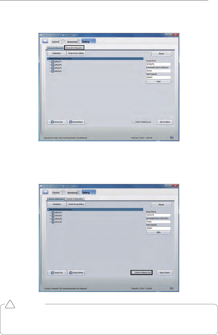
12 Click General Configuration tab to move to TMS interface information management screen.
Locking indoor unit address
When indoor unit address lock is set, central control address cannot be changed from the indoor
unit remote controller.
CAUTION
• Beware that the central control address cannot be changed from the remote controller
when the address lock is set.
• Address lock function is limited to some indoor/outdoor units and remote controllers.
!
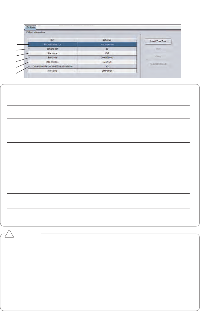
13 Modify each category except the site code by referring to the next page’s TMS interface
information.
ڸ
ڹ
ں
ڻ
ڼ
ڽ
38 INTERNET BRIDGE SETTING
Note : TMS interface information
TMS interface information to input are as follows
Category Description
①Management system address Input TMS system internet address (http://tms2.lge.com).
③Site name Input the site name.
⑤Site address Input the site address.
※You can search the address in http://maps.google.co.kr.
Input the address searched from the above site.
⑥Monitoring period Input the monitoring period in the units of seconds.
(Minimum monitoring period is 10 seconds)
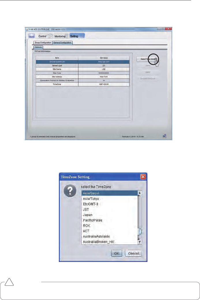
⑦Time Zone Settings Press the button [Select TimeZone] on the right side, and
then enter the information of the city closest to the site.
Site code is unique for each site.
④Site code If you press [Request site code] button on the right side, the
online request for site code registration is submitted, and if
you press [View] button within about 1 min., you can check
the issued site code.
②Connection PORT number Input TMS system communication port number.
(Select one from 21 or 23)
CAUTION
Save
When the contents of the table are changed, you must press [Save] button to save the
changed information.
TMS interface information
Information related to TMS interface must be handled by an installation technician with instal-
lation qualifications. Even if you input the above information, you may not be able use TMS
interface right away. If you have inquiries or questions related to the above, please contact
service center or installation specialty store acknowledged by the company.
Time Zone Settings
If you do not set the time zone, you will not be able to set the TMS linked information.
In countries where the application of the daylight saving, please use it to check the time.
!
INTERNET BRIDGE SETTING 39
14 Click the 'Select TimeZone' button
15 Select the city closest to the location of the installation of the product.
CAUTION
If you do not set the TimeZone, you will not be able to set the TMS linked information.
!
40 INTERNET BRIDGE SETTING
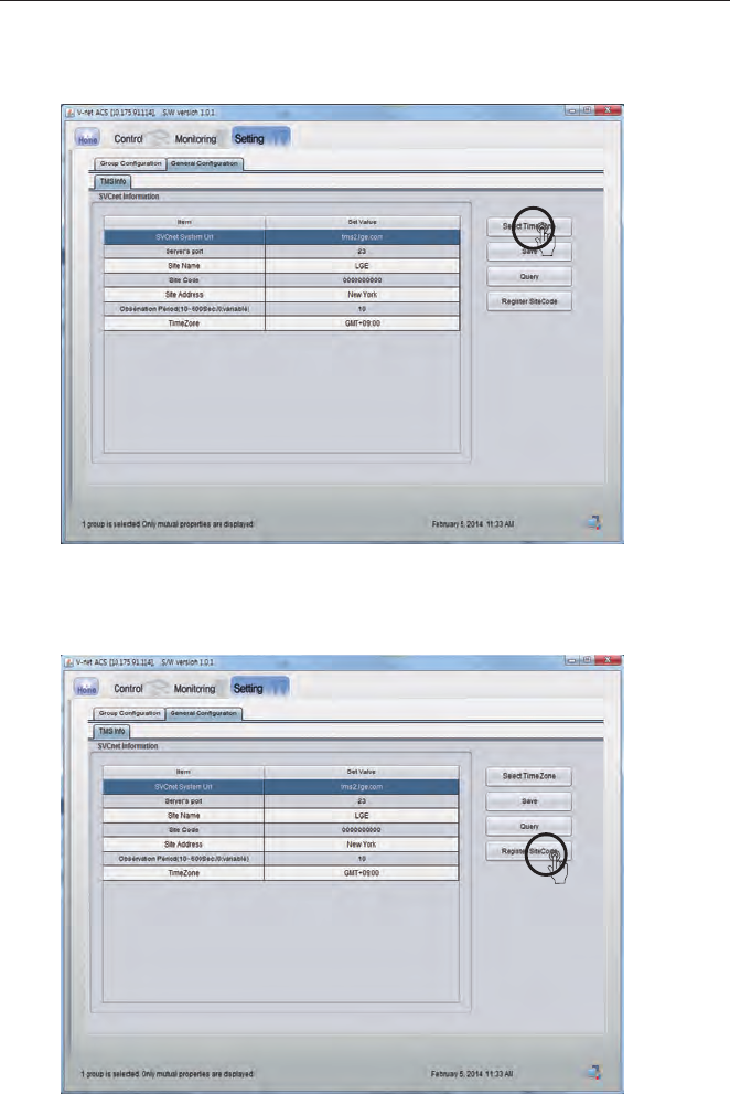
16 Click Save button to save TMS interface information.
17 Click Register site code button to request the site code.
INTERNET BRIDGE SETTING 41
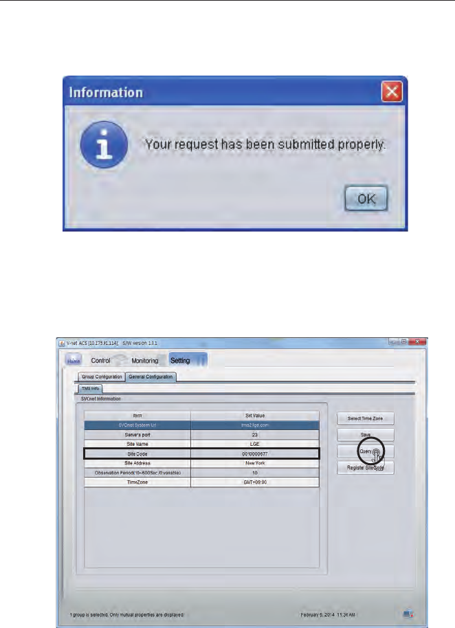
18 When the popup window appears, press Confirm button.
19 If you press Query button within about 1 min., you can see that the site code is changed.
42 INTERNET BRIDGE SETTING
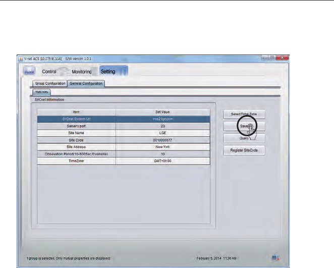
20 Click Save button to save the changed information.
21 Check the site code, and apply for registration in TMSII home page.
(Refer to TMS User Manual)
※Record the site code separately and directly hand over to the customer.

CHECKLIST BEFORE INSTALLATION INQUIRIES 43
Major Function Possible causes Corrective action
Internet bridge LED 2
does not blink.
• Did you complete the group set-
ting using ACCS?
• Is RS485 cable correctly connect-
ed to BUS-A and BUS-B?
• Set the indoor unit and outdoor
unit groups and run again.
• Check RS485 connections of BUS-
A and BUS-B.
LGE-xx-xx-xx is not
searched in the
smart phone.
• Is the internet bridge LED 1 ON?
• Is Wi-Fi signal weak?
• Is the internet module LED 01
blinking?
• Press the setting the AP switch
for 1 second to check if LED 01
starts blinking.
• Maintain distance with internet
bridge to be 0.3~2 m.
• Run the smart phone Wi-Fi search
again.
Internet bridge wire-
less communication
does not work.
• Is AP turned off?
• Is AP at a long distance?
• Turn on the AP.
• Install the AP within 10m from the
internet bridge.
Internet bridge wired
communication does
not work.
• Is LAN cable disconnected from
the wired LAN connector?
• Connect LAN cable to the wired
LAN connector.
Wi-Fi is connected,
but it does not work.
• Is the internet bridge LED 1 ON?
• Did you input AP password cor-
rectly when you register the
equipment?
• Did you register as wired during
the network setting?
• If Wi-Fi connection is unstable, it
may not work correctly.
• If you did not input the wireless
AP password correctly during the
Network setting, Wi-Fi connection
may not work correctly. Input
correct wireless AP password.
• During the network setting, set as
wireless.
IP_Search program
cannot search the
internet bridge.
• Is the internet bridge LED 1 ON?
• Is the PC connected to the same
network (AP) with the internet
bridge?
• Perform the network setting
again.
• Connect the PC to the same net-
work (AP) as the internet bridge.
IP_Search program
can search the inter-
net bridge, but JAVA
program does not
open.
• Did you make Internet bridge net-
work settings to DHCP?
• Please restart internet bridge by
pressing the AP switch of internet
bridge until the LED1 blinks twice
(about 7 seconds).
CHECKLIST BEFORE INSTALLATION INQUIRIES
Trouble Shooting Guide

44 CHECKLIST BEFORE INSTALLATION INQUIRIES
Major Function Possible causes Corrective action
LG ACCS GUI is not
operational.
• Are several programs running in
the computer?
• Close Explorer window and run a
new explorer to access again.
• In the process manager, end all
iexplore.exe processes and
access the internet bridge again.
In LG ACCS, ventila-
tion device becomes
network error state
(CH 242).
• Is RS-485 cable correctly connect-
ed?
• Is there remote controller commu-
nication defect?
• Is PI485 DIP switch setting cor-
rect?
• Is central control indoor unit
address set?
• Connect RS-485 cable to BUS-A
and BUS-B.
• Solve the remote controller com-
munication defect problem.
• Refer to PI485 manual for DIP
switch setting.
• Set the indoor unit address.
CH 242 (network
error) keeps appear-
ing and disappearing
in the internet bridge
controller.
• Are all RS-485 communication
lines connected to each other?
• Is there any overlapping indoor
unit address setting?
• Remove the interconnecting com-
munication lines outside the com-
munication lines connecting to the
internet bridge.
• Assign unique address to each
indoor unit so that there is no
indoor unit with overlapped
address.
16 rooms central
controller and inter-
net bridge interfaced
and installed, but
some indoor units
are not recognized or
central control com-
mands are not well
performed.
• Is the simple central controller DIP
switch setting correct?
• Are the simple central controller
and the controlled indoor unit
physically connected on the same
line?
• Set all central controllers (16
rooms central controller) to Slave
mode, and reset the power.
• Modify the connections so that
the simple central controller is
surely on the same RS-485 com-
munication line with the controlled
indoor unit.
Trouble Shooting Guide

CHECKLIST BEFORE INSTALLATION INQUIRIES 45
OPEN SOURCE SOFTWARE NOTICE
To obtain the source code under GPL, LGPL, MPL and other open source licenses, that is con-
tained in this product, please visit http://opensource.lge.com.
In addition to the source code, all referred license terms, warranty disclaimers and copyright
notices are available for download.
LG Electronics will also provide open source code to you on CD-ROM for a charge covering the
cost of performing such distribution (such as the cost of media, shipping and handling) upon
email request to opensource@lge.com. This offer is valid for three (3) years from the date on
which you purchased the product.

46 CHECKLIST BEFORE INSTALLATION INQUIRIES
NOTE
FCC Compliance Information
This device complies with Part 15 of FCC Rules. Operation is subject to the following two
conditions:
(1) This device may not cause harmful interference, and
(2) This device must accept any interference received. Including interference that may cause
undesired operation.
Changes or Modifications that are not expressly approved by the manufacturer could void the
user's authority to operate the equipment.
This equipment has been tested and found to comply with the limits for a class B digital device,
pursuant to Part 15 of the FCC Rules. These limits are designed to provide reasonable protection
against harmful interference in a residential installation. This equipment generates uses and can
radiate radio frequency energy and, if not installed and used in accordance with the instructions,
may cause harmful interference to radio communications. However, there is no guarantee that
interference will not occur in a particular installation. If this equipment does cause harmful
interference or television reception, which can be determined by turning the equipment off and
on, the user is encouraged to try to correct the interference by one or more of the following
measures:
- Reorient or relocate the receiving antenna.
- Increase the separation between the equipment and receiver.
- Connect the equipment into an outlet on a circuit different from that to which the receiver is
connected.
- Consult the dealer or an experienced radio/TV technician for help
RF Exposure statement
Warning: Exposure to Radio Frequency Radiation The radiated output power of this device is far
below the FCC radio frequency exposure limits. Nevertheless, the device should be used in such
a manner that the potential for human contact during normal operation is minimized. In order to
avoid the possibility of exceeding the FCC radio frequency exposure limits, human proximity to
the antenna should not be less than 20 cm during normal operation. The gain of the antenna for
WLAN must not exceed dBi
Can be found under the Display Grant section of www.fcc.gov/oet/ea/fccid after searching on
FCC ID : BEJPWFMDB000
CHECKLIST BEFORE INSTALLATION INQUIRIES 47
CAUTION
Changes or modifications not expressly approved by the manufacturer responsible for
compliance could void the user’s authority to operate the equipment.
!
Class B device
NOTE
!
This equipment may generate or use radio frequency energy. Changes or modifications to
this equipment may cause harmful interference unless the modifications are expressly
approved in the instruction manual. The user could lose the authority to operate this equip-
ment if an unauthorized change or modification is made.
Disposal of your old appliance
1 When this crossed-out wheeled bin symbol is attached to a product it means the
product is covered by the European Directive 2002/96/EC. 2 All electrical and elec-
tronic products should be disposed of separately from the municipal waste stream
via designated collection facilities appointed by the government or the local author-
ities.
3 The correct disposal of your old appliance will help prevent potential negative con-
sequences for the environment and human health.
4 For more detailed information about disposal of your old appliance, please contact
your city office, waste disposal service or the shop where you purchased the prod-
uct.