LG Electronics USA REAP10WHE PCS Block E Repeater User Manual
LG Electronics USA PCS Block E Repeater
UserManual.wiki
>
LG Electronics USA
>
REAP10WHE User Manual
User Manual
Navigation menu
Upload a User Manual
Namespaces
Wiki Guide
HTML
PDF
Info
Views
User Manual
Discussion / Help
Navigation
![5/39 1.1.1.1. OverviewOverviewOverviewOverview ş [[[[FigureFigureFigureFigure 1111----1111]]]] LGE NOTCHCELL Repeater LGE NOTCHCELL Repeater LGE NOTCHCELL Repeater LGE NOTCHCELL Repeater LGE NOTCHCELL repeaters are used to fill out uncovered areas in CDMA mobile systems, such as base station fringe areas, road tunnels, business and industrial buildings, etc. A NOTCHCELL repeater receives signals from a base station, amplifies and retransmits the signals to mobile stations. Also it receives, amplifies and retransmits signals in the opposite direction. Both directions are served simultaneously. To be able to receive and transmit signals in both directions, the repeater is connected to a donor antenna directed towards the base station and to a distributor antenna directed towards the area to be covered. Control of the repeaters is performed using a desktop or notebook loaded with the LGE OMT, Operation and Maintenance Terminal, which can communicate with the repeaters either locally or remotely via wireless data modem. Remote operation can be performed either via CDMA net. To be able to control many LGE NOTCHCELL repeaters in common, there is a Sprint EMS center.](https://usermanual.wiki/LG-Electronics-USA/REAP10WHE/User-Guide-443118-Page-6.png)
![8/39 2.1.1 Main Box EBLUE TOOTHLOCAL OMTALARMEXT ALARMDONORANTU/L MO NPSUD/L MONAC INSERVICEANTCC EEC E RF I NLNAA4A1A2VCC(12V DC)A8LNA OpenGNDLNA FaultRSSICONV.PLLRF O UTUDC-ULGNDNot UsedOSC AlarmNot UsedTempClockLDEnableDataUDC OpenGNDA1BA2BA4BA8BA16BVCC(12V DC)VCC(12V DC)VCC(12V DC)UDC-DLLNAGNDLNAOpen A8A2A4RSSIA1LNA FaultRF INPLLRF OUTCONV.A1BA2BA4BGNDVCC(12V DC)VCC(12V DC)A16BA8BUDC OpenOSC AlarmNot UsedTempDataGNDNot UsedClockLDEnableMCPA-DLyk{k}jjw~yhu{vwynukyz{ DOOR SILK ར $ BRACKET / LGREP. Cont rol UnitPOWERRUNWNMCGUIOPERATINGRESETDPX- BSDPX-MSLG Ele c tr oni cs lnc.MADE IN KOREAUSCRE220219CCC ƄCCC [Figure 2[Figure 2[Figure 2[Figure 2----1] Main box1] Main box1] Main box1] Main box Item Specification Remarks RF connector N-female Size 450(W) X 635(H) X 243(D) mm Weight Less than 43Kg](https://usermanual.wiki/LG-Electronics-USA/REAP10WHE/User-Guide-443118-Page-9.png)
![9/39 2.1.2 PSU box LG [Figure 2[Figure 2[Figure 2[Figure 2----2] PSU box2] PSU box2] PSU box2] PSU box Item Specification Remarks Size 450(W) X 334(H) X 265(D) mm Weight Less than 25Kg](https://usermanual.wiki/LG-Electronics-USA/REAP10WHE/User-Guide-443118-Page-10.png)
![11/39 2.2.1 Donor Antenna [Figure 2[Figure 2[Figure 2[Figure 2----3] Donor antenna3] Donor antenna3] Donor antenna3] Donor antenna Item Specification Remarks RF connector 7/16” DIN-female Size 700(W)1000(H)150(D) mm Weight Less than 20kg](https://usermanual.wiki/LG-Electronics-USA/REAP10WHE/User-Guide-443118-Page-12.png)
![12/39 2.2.2 Distributor Antenna [Figure 2[Figure 2[Figure 2[Figure 2----4] Distributor antenna4] Distributor antenna4] Distributor antenna4] Distributor antenna Item Specification Remarks RF connector 7/16” DIN-female Size 310(W)1500(D)120(H) mm Weight Less than 17kg](https://usermanual.wiki/LG-Electronics-USA/REAP10WHE/User-Guide-443118-Page-13.png)
![13/39 2.2.3 Mount Pole [Figure 2[Figure 2[Figure 2[Figure 2----5] Mount pole5] Mount pole5] Mount pole5] Mount pole Item Specification Remarks Length 2500 mm Weight Less than 6kg](https://usermanual.wiki/LG-Electronics-USA/REAP10WHE/User-Guide-443118-Page-14.png)
![19/39 3.3 Installing the repeater & Antenna The installation methods of the repeater vary depending on the types of support (steel tower), location, and demand of the carrier. This standard specifies the general supporting methods and is subject to the types of support. [Figure 3[Figure 3[Figure 3[Figure 3----1] Definition of 1] Definition of 1] Definition of 1] Definition of assembliesassembliesassembliesassemblies (ex. electric pole) (ex. electric pole) (ex. electric pole) (ex. electric pole) Feeder Main & PSU box Distributor Antenna Mount Donor Antenna Safety facilities](https://usermanual.wiki/LG-Electronics-USA/REAP10WHE/User-Guide-443118-Page-20.png)
![21/39 [Figure 3[Figure 3[Figure 3[Figure 3----2] Band installation diagram 1 (steel tower type)2] Band installation diagram 1 (steel tower type)2] Band installation diagram 1 (steel tower type)2] Band installation diagram 1 (steel tower type)](https://usermanual.wiki/LG-Electronics-USA/REAP10WHE/User-Guide-443118-Page-22.png)
![22/39 [Figure 3[Figure 3[Figure 3[Figure 3----3] Band installation diagram 2 (3] Band installation diagram 2 (3] Band installation diagram 2 (3] Band installation diagram 2 (electricelectricelectricelectric pole type) pole type) pole type) pole type)](https://usermanual.wiki/LG-Electronics-USA/REAP10WHE/User-Guide-443118-Page-23.png)
![23/39 [Figure 3[Figure 3[Figure 3[Figure 3----4] Band installation diagram 34] Band installation diagram 34] Band installation diagram 34] Band installation diagram 3 (location of cabinet) (location of cabinet) (location of cabinet) (location of cabinet) [Figure 3[Figure 3[Figure 3[Figure 3----5] Band set5] Band set5] Band set5] Band set Band Set](https://usermanual.wiki/LG-Electronics-USA/REAP10WHE/User-Guide-443118-Page-24.png)
![24/39 Installing LInstalling LInstalling LInstalling L----Type angleType angleType angleType angle The AC distribution panel shall be, in principle, on the left of the repeater. When installing the repeater on the roof, the standard height to the bottom of the repeater shall be 1.2m, and 4m when on a field. [Figure 3[Figure 3[Figure 3[Figure 3----6] L6] L6] L6] L----Type installation diagram 1 (steel tower type)Type installation diagram 1 (steel tower type)Type installation diagram 1 (steel tower type)Type installation diagram 1 (steel tower type)](https://usermanual.wiki/LG-Electronics-USA/REAP10WHE/User-Guide-443118-Page-25.png)
![25/39 [Figure 3[Figure 3[Figure 3[Figure 3----7] L7] L7] L7] L----Type installation diagram 2 (location of cabinet)Type installation diagram 2 (location of cabinet)Type installation diagram 2 (location of cabinet)Type installation diagram 2 (location of cabinet)](https://usermanual.wiki/LG-Electronics-USA/REAP10WHE/User-Guide-443118-Page-26.png)
![26/39 [Figure 3[Figure 3[Figure 3[Figure 3----8] L8] L8] L8] L----Type installation diagram 3 (steel tower type)Type installation diagram 3 (steel tower type)Type installation diagram 3 (steel tower type)Type installation diagram 3 (steel tower type)](https://usermanual.wiki/LG-Electronics-USA/REAP10WHE/User-Guide-443118-Page-27.png)
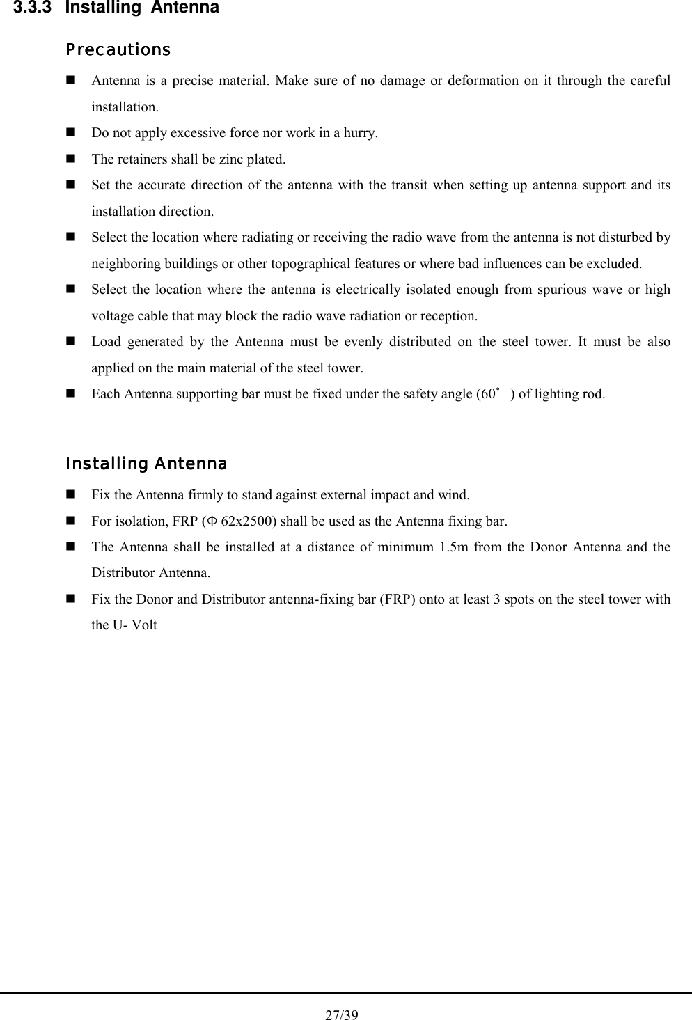
![28/39 [Figure 3[Figure 3[Figure 3[Figure 3----9] Antenna Installation9] Antenna Installation9] Antenna Installation9] Antenna Installation](https://usermanual.wiki/LG-Electronics-USA/REAP10WHE/User-Guide-443118-Page-29.png)
![29/39 3.3.4 Installing the feeder cable Installing the feeder cable Installing the feeder cable Installing the feeder cable Installing the feeder cable 1) Connection between the antenna and the repeater Use two NOTCHCELL Antennas. Install a pair of 1/2” cable from the arrestor on the bottom of the repeater cabinet to the Antenna. The Standard of feeder cable between the Antenna and the repeater shall be conformed to that of the carrier. The Connector for the feeder cable and the connector for the 36mm Flexible Conduit End Cap are installed on the bottom of the repeater and the NOTCHCELL Antenna. 2) Connecting the feeder cable connector 1/2” feeder cable [Figure 3[Figure 3[Figure 3[Figure 3----10] 1/210] 1/210] 1/210] 1/2””””Feeder Cable Diagram Feeder Cable Diagram Feeder Cable Diagram Feeder Cable Diagram [Table 3[Table 3[Table 3[Table 3----1] Example of Connectors for 1/21] Example of Connectors for 1/21] Example of Connectors for 1/21] Example of Connectors for 1/2””””feeder cable feeder cable feeder cable feeder cable Item ARRESTER 1/2” F Cable Antenna Type N-Female N-Male Din-Male Din-Female ConnectorQ’ty - 2 2 - Type - 1/2” F Cable - Feeder cable Q’ty - 2 -](https://usermanual.wiki/LG-Electronics-USA/REAP10WHE/User-Guide-443118-Page-30.png)
![31/39 [Figure 3[Figure 3[Figure 3[Figure 3----11] Shield Cable and Connector11] Shield Cable and Connector11] Shield Cable and Connector11] Shield Cable and Connector Assemble the Conduit End Cap (repeater accessory) at both ends of 36mm Flexible Conduit. Insert the assembled 1/2” feeder cable (shield cable) into the 36mm Flexible Conduit. [Figure 3[Figure 3[Figure 3[Figure 3----12] Feeder Cable at Repeater Side12] Feeder Cable at Repeater Side12] Feeder Cable at Repeater Side12] Feeder Cable at Repeater Side After installing and tying the cable, connect the connector to the bottom of the antenna and then apply the Conduit End Cap. [Figure 3[Figure 3[Figure 3[Figure 3----13] Connector on the Antenna Side13] Connector on the Antenna Side13] Connector on the Antenna Side13] Connector on the Antenna Side](https://usermanual.wiki/LG-Electronics-USA/REAP10WHE/User-Guide-443118-Page-32.png)
![32/39 Compress the Shield cable on the repeater with the heat shrink tube. Connect the feeder cable connector to the arrestor onto the bottom of the repeater, and then apply the Conduit End Cap. [Figure 3[Figure 3[Figure 3[Figure 3----14] Installing the connector on the repeater side 14] Installing the connector on the repeater side 14] Installing the connector on the repeater side 14] Installing the connector on the repeater side 3.3.5 Grounding Three types of grounding are applied - system grounding, arrester grounding, and steel tower grounding. The arrester and the fixing studs are installed on the bottom of the repeater. The steel tower grounding and arrester grounding shall be in conformity to the standard of the steel tower manufacturer. GeneralGeneralGeneralGeneral Use the GV cable for the grounding. Branch point shall be finished with C-tap and the heat shrink tube. When branching off outside, make sure to prevent the inflow of rain. Grounding shall be, in principle, connected from the Under Ground grounding. Install the grounding cable with PVC Flexile Pipe and Flexible Conduits for the external protection. Connector Conduit End Cap](https://usermanual.wiki/LG-Electronics-USA/REAP10WHE/User-Guide-443118-Page-33.png)
![33/39 System groundingSystem groundingSystem groundingSystem grounding The Under Ground shall be made with up to 3 ground bars or with ground resistance of 20Ω or lower. After excavating the ground to 70Cm from the surface, cast the ground bars at a distance of at least 3m between one another. Connect the ground bars to the PVC Pipe with Bare Wire(38շ) and C-Tap. Connect GV 38շ x 1C to the stud on the bottom of the cabinet with the underground bar. Use the 1 Hole Terminal Lugs, and finish with the Green Shrink Tube. For the arrester grounding of the steel tower, connect GV 38mm² x 1C from the Under Ground [[[[FigureFigureFigureFigure 3 3 3 3----15]15]15]15] Ground Cable Diagra Ground Cable Diagra Ground Cable Diagra Ground Cable Diagrammmm AC distribution panel groundingAC distribution panel groundingAC distribution panel groundingAC distribution panel grounding For Surge Protector ground of the AC distribution panel, connect GV 14շ cable to the repeater cabinet grounding cable (GV 38շ), branching it off with C-Tap (38-14mm). Connect to the ground Terminal Block in the AC distribution panel with the Fork Type Terminal Lug.](https://usermanual.wiki/LG-Electronics-USA/REAP10WHE/User-Guide-443118-Page-34.png)
![34/39 3.3.6 Installing AC power cable AC distribution panel AC distribution panel AC distribution panel AC distribution panel Install the AC distribution panel on the steel tower to supply AC power to PSU Box. 1) AC distribution panel specification The AC distribution panel consists of a Breaker (30A), a Surge-Protector (40KA), a two - hole outlet, and terminal blocks. The cabinet shall be waterproof and equipped with cable bushings on the bottom. [[[[FigureFigureFigureFigure 3 3 3 3----16]16]16]16] AC Distribution Panel Diagram AC Distribution Panel Diagram AC Distribution Panel Diagram AC Distribution Panel Diagram](https://usermanual.wiki/LG-Electronics-USA/REAP10WHE/User-Guide-443118-Page-35.png)
![35/39 Installing AC power cable Installing AC power cable Installing AC power cable Installing AC power cable Connect the CV 5.5շ ~ CV 22շ x 2C power cable from the accumulative wattmeter to the AC distribution panel with the Ring Type Terminal Lugs and Flexible Conduits. Use the Fork Type Terminal Lugs when connecting the AC power cable. No cable will have contact points inside the conduit, and distribution/connection shall be allowed only in the AC distribution panel. Use 22mm flexible conduit when installing the power cable. Fix the conduit firmly on the wall or the ground with Saddle. Fill up the vacant cable busing holes on the AC distribution panel with silicon. Fit the end of the flexible conduits with the conduit caps or by taping. All the Flexible Conduits must be sealed tight. [[[[FigureFigureFigureFigure 3 3 3 3----17]17]17]17] Flexible Conduit End Fitting Flexible Conduit End Fitting Flexible Conduit End Fitting Flexible Conduit End Fitting](https://usermanual.wiki/LG-Electronics-USA/REAP10WHE/User-Guide-443118-Page-36.png)
![36/39 4.4.4.4. OperatioOperatioOperatioOperationnnn 4.1 Isolation test procedure of Antenna [Figure 4[Figure 4[Figure 4[Figure 4----1] Isolation test1] Isolation test1] Isolation test1] Isolation test 1) Set-up the equipment as shown in [Figure 4-1] Isolation test 2) Set up the analyzer for the highest possible sensitivity (more than 100dBm) for 0dBm source-power. 3) Set the analyzer to ‘peak search mode’. 4) After calibrated cable loss between Measurement Equip and Antenna, set the output-power of the generator to 0 dBm. 5) Turn on Signal Generator Output 6) Measure the Antenna Isolation, using spectrum analyzer. The minimum isolation is the highest value of the curve (excepting carriers transmitted by surrounding BS). 7) Change measurement-ports to check for the opposite direction by repeating the measurement procedure. 8) Repeat the test for the opposite path of the repeater. Step (1) to (7). Isolation per carrier frequency is worse value.](https://usermanual.wiki/LG-Electronics-USA/REAP10WHE/User-Guide-443118-Page-37.png)
![38/39 8) When set Uplink path’s maximum output and maximum gains, consider and decide RSSI and antenna isolation. Also, Repeater's maximum gains establishment considers 15 dBs Margin in isolation of antenna. Repeater’s maximum gain = Antenna isolation – 15dB (Margin) But, in the case of Uplink path, when set output and gains because it is no fixed input level, set on the basis of Noise level. Up Link Gain = 113 [dBm] + BS_ Noise Level [dBm] – Repeater_Feeder cable loss [dB] – Donor ant. Gain [dBd] – Path Loss [dB] – BS_Ant. Gain [dBd] – BS_Feeder cable loss [dB] Air Loss (dB) = 20log (1/λ) + 20log (4π) + 20log (d) Only, preceding formula recommands to apply in Line of site section of BS and Repeater. However, can be different from noise level and theoretical arithmetic level by change of RF environment. 9) When inspect Uplink path's output waveform, inspect using Monitoring port (SMA-Female type) on Main box’s left side lower column. 10) In Local GUI's control window, consider site situation about items below and establish properly. Parameters to act Alram that correspond to each input/output Parameters to act ALC function Parameters to act Shutdown function 11) After input each setting value in Local GUI's control window, moving by monitor window, confirm alarm's existence and nonexistence. 12) Erase alarm that happen at setup process in Local GUI's History window.](https://usermanual.wiki/LG-Electronics-USA/REAP10WHE/User-Guide-443118-Page-39.png)