LG Electronics USA REAP10WHE PCS Block E Repeater User Manual
LG Electronics USA PCS Block E Repeater
User Manual

NOTCHCELL
NOTCHCELLNOTCHCELL
NOTCHCELL
Operati
OperatiOperati
Operation Manual
on Manualon Manual
on Manual
SMD-014-PMB210(V1.0)

1/39
Copyright
CopyrightCopyright
Copyright
Copyright of this manual belongs to LG Electronics, Inc.
Reproduction, distribution or revision of part or all of contents in this manual in any form without written
permission of LG Electronics, Inc. is prohibited.
Registered Trademark
Registered TrademarkRegistered Trademark
Registered Trademark
LG Electronics, are registered trademarks of LG Electronics, Inc.
Other products and company names mentioned herein this manual might be trademarks or trade names of
their respective owners.
Copyright © 2003 LG Electronics, Inc. All Rights Reserved
The results of using the information not mentioned in this manual or the risk of misunderstanding
this document remain with the user.
The information in this manual is subject to change due to function enhancement, change o
f
design, etc. If you want the modified manual or have any question on this manual, please contac
t
us with information below:
Address : Customer Support Center, LG Research Complex 1, 533 Hogye 1-dong, Dongan-
gu, Anyang-shi, Kyungki-do, South Korea
Tel : 82-1588-9388
/
/

2/39
Revision History
Revision HistoryRevision History
Revision History/
Version Date of revision Reason for revision Revision Description
V1.0 01. 04. 2004 First Edition

3/39
Content
ContentContent
Content
1.
1.1.
1./Overview
OverviewOverview
Overview ................................
................................................................
................................................................
................................................................
......................................
............
...... 5
55
5/
2.
2.2.
2./Specifications
SpecificationsSpecifications
Specifications ................................
................................................................
..............................................................
............................................................
.............................. 6
66
6/
2.1/Specificat .................................................................................................................................6/
2.1.1/Main Box .................................................................................................................................... 8/
2.1.2/PSU box...................................................................................................................................... 9/
2.2/Antenna .................................................................................................................................10/
2.2.1/Donor Antenna.......................................................................................................................... 11/
2.2.2/Distributor Antenna................................................................................................................... 12/
2.2.3/Mount Pole................................................................................................................................ 13/
3.
3.3.
3./Installation
InstallationInstallation
Installation ................................
................................................................
................................................................
................................................................
..................................
....
..14
1414
14/
3.1/General..................................................................................................................................14/
3.1.1/Overview................................................................................................................................... 14/
3.1.2/Structure.................................................................................................................................... 14/
3.1.3/Scope of application.................................................................................................................. 14/
3.1.4/Safety management................................................................................................................... 14/
3.2/Installing information..............................................................................................................17/
3.2.1/Installation site.......................................................................................................................... 17/
3.2.2/Installing support ...................................................................................................................... 18/
3.3/Installing the repeater & Antenna ..........................................................................................19/
3.3.1/General...................................................................................................................................... 20/
3.3.2/Installing band .......................................................................................................................... 20/
3.3.3/Installing Antenna ..................................................................................................................... 27/
3.3.4/Installing the feeder cable ......................................................................................................... 29/
3.3.5/Grounding ................................................................................................................................. 32/
3.3.6/Installing AC power cable......................................................................................................... 34/
4.
4.4.
4./Operation
OperationOperation
Operation................................
................................................................
................................................................
................................................................
.....................................
..........
.....36
3636
36/
4.1/Isolation test procedure of Antenna.......................................................................................36/
4.1.1/Power-up sequence ................................................................................................................... 37/
4.1.2/Repeater control application ..................................................................................................... 37/
5/39
1.
1.1.
1.
Overview
OverviewOverview
Overview
ş
[
[[
[Figure
FigureFigure
Figure
1
11
1-
--
-1
11
1]
]]
] LGE NOTCHCELL Repeater
LGE NOTCHCELL Repeater LGE NOTCHCELL Repeater
LGE NOTCHCELL Repeater
LGE NOTCHCELL repeaters are used to fill out uncovered areas in CDMA mobile systems, such as
base station fringe areas, road tunnels, business and industrial buildings, etc.
A NOTCHCELL repeater receives signals from a base station, amplifies and retransmits the signals to
mobile stations. Also it receives, amplifies and retransmits signals in the opposite direction. Both
directions are served simultaneously.
To be able to receive and transmit signals in both directions, the repeater is connected to a donor
antenna directed towards the base station and to a distributor antenna directed towards the area to be
covered.
Control of the repeaters is performed using a desktop or notebook loaded with the LGE OMT,
Operation and Maintenance Terminal, which can communicate with the repeaters either
locally or remotely via wireless data modem. Remote operation can be performed either via CDMA net.
To be able to control many LGE NOTCHCELL repeaters in common, there is a Sprint EMS center.

6/39
2.
2.2.
2.
Specifications
SpecificationsSpecifications
Specifications
2.1 Specificat
Description Specification
Frequency Bands A, B, D, or E
Output Power (DL) +40dBm/carrier for 1 carrier,
+37dBm/carrier for 2 carriers
+34dBm/carrier for 4 carriers,
+29.5dBm/carrier for 11 carriers.
Output Power (UL) +25dBm/carrier for 1 carrier,
+22dBm/carrier for 2 carriers
+19dBm/carrier for 4 carriers,
+14.5dBm/carrier for 11 carriers
Input Power (DL) -55 ~ -30dBm/carrier for 1 carrier
-65 ~ -40dBm/carrier for 11carriers
Input Power (UL) -70 ~ -45dBm/carrier for 1 carrier
-80 ~ -55dBm/carrier for 11carriers,
Filter Bandwidth 5MHz for Bands D or E
15MHz for Bands A or B
In band Flatness 1dB max in each 1.25MHz channel
2dB max in each PCS block
Noise Figure 4dB max at max gain
8dB max at min gain
Maximum Input without damage +10dBm
VSWR (Pin/Pout port) 1.5:1 max
Input Impedance 50 ohms

7/39
Description Specification
Gain Range 70 dB to 95 dB
Gain steps 1dB
Signal Delay 5usec max
Power 110VAC +/-20%, 50/60Hz+/-5%
Alarm & Status Synthesizer, LNA, Power Amplifier, Output power, RSSI,
PSU, Battery, Door
Interface RS-232 and wireless modem
Control Gain, Auto Level Control, Power Amplifier On/Off,
Software Shutdown, Alarm masking
Cooling Air convection
Temperature Operating: -40 to +55
Storage: -40 to +85
Size Main Box: 450(W) X 635(H) X 243(D) mm
PSU Box: 450(W) X 334(H) X 265(D) mm
Weight Main Box: 95Ibs. (43kg)
PSU Box: 55Ibs. (25kg)
Weather Resistance NEMA 4X (IP65)
Wind Pressure 60m/s
Connector
RF
Monitoring
Control
AC Power
Type N female
Type SMA female
MS connector
MS connector
8/39
2.1.1 Main Box
E
BLUE TOOTH
LOCAL OMT
ALARMEXT ALARM
DONOR
ANT
U/L MO N
PSU
D/L MON
AC IN
SERVICE
ANT
CC EEC E
RF I N
LNA
A4
A1
A2
VCC(12V DC)
A8
LNA Open
GND
LNA Fault
RSSI
CONV.
PLL
RF O UT
UDC-UL
GND
Not Used
OSC Alarm
Not Used
Temp
Clock
LD
Enable
Data
UDC Open
GND
A1B
A2B
A4B
A8B
A16B
VCC(12V DC)
VCC(12V DC)
VCC(12V DC)
UDC-DL
LNA
GND
LNAOpen
A8
A2
A4
RSSI
A1
LNA Fault
RF IN
PLL
RF OUT
CONV.
A1B
A2B
A4B
GND
VCC(12V DC)
VCC(12V DC)
A16B
A8B
UDC Open
OSC Alarm
Not Used
Temp
Data
GND
Not Used
Clock
LD
Enable
MCPA-DL
yk
{k
}jj
w~y
hu{
vwy
nuk
yz{
DOOR SILK ར $
BRACKET /
LG
REP. Cont rol Unit
POWER
RUN
WNMC
GUI
OPERATING
RESET
DPX- BS
DPX-MS
LG Ele c tr oni cs lnc.
MADE IN KOREA
USCR
E220219
CCC
Ƅ
CCC
[Figure 2
[Figure 2[Figure 2
[Figure 2-
--
-1] Main box
1] Main box1] Main box
1] Main box
Item Specification Remarks
RF connector N-female
Size 450(W) X 635(H) X 243(D) mm
Weight Less than 43Kg
9/39
2.1.2 PSU box
LG
[Figure 2
[Figure 2[Figure 2
[Figure 2-
--
-2] PSU box
2] PSU box2] PSU box
2] PSU box
Item Specification Remarks
Size 450(W) X 334(H) X 265(D) mm
Weight Less than 25Kg

10/39
2.2 Antenna
Description Specification
Frequency 1850~1910MHz, 1930~1990MHz
VSWR 1.5:1 max
Gain 17dBd1
Front-To-Back-Ratio 45dB min
Front-To-first Side Ratio 13dB min
Impedance 50 ohms
Polarization Vertical
Available Power 200W max
Connector 7/16” DIN female
Waterproof NEMA4X (IP65)
Wind Pressure 60m/s
Isolation (Donor to Distributor) 100dB min
Horizontal HPBW
Donor Antenna
Distributor Antenna
203
455
Vertical HPBW
Donor Antenna
Distributor Antenna
203
82
Size
Donor Antenna
Distributor Antenna
700(W) x 1000(H) x 150(D) mm
310(W) x 1500(H) x 120(D) mm
Weight
Donor Antenna
Distributor Antenna
44Ibs. (20kg)
38Ibs. (17kg)
11/39
2.2.1 Donor Antenna
[Figure 2
[Figure 2[Figure 2
[Figure 2-
--
-3] Donor antenna
3] Donor antenna3] Donor antenna
3] Donor antenna
Item Specification Remarks
RF connector 7/16” DIN-female
Size 700(W)1000(H)150(D) mm
Weight Less than 20kg
12/39
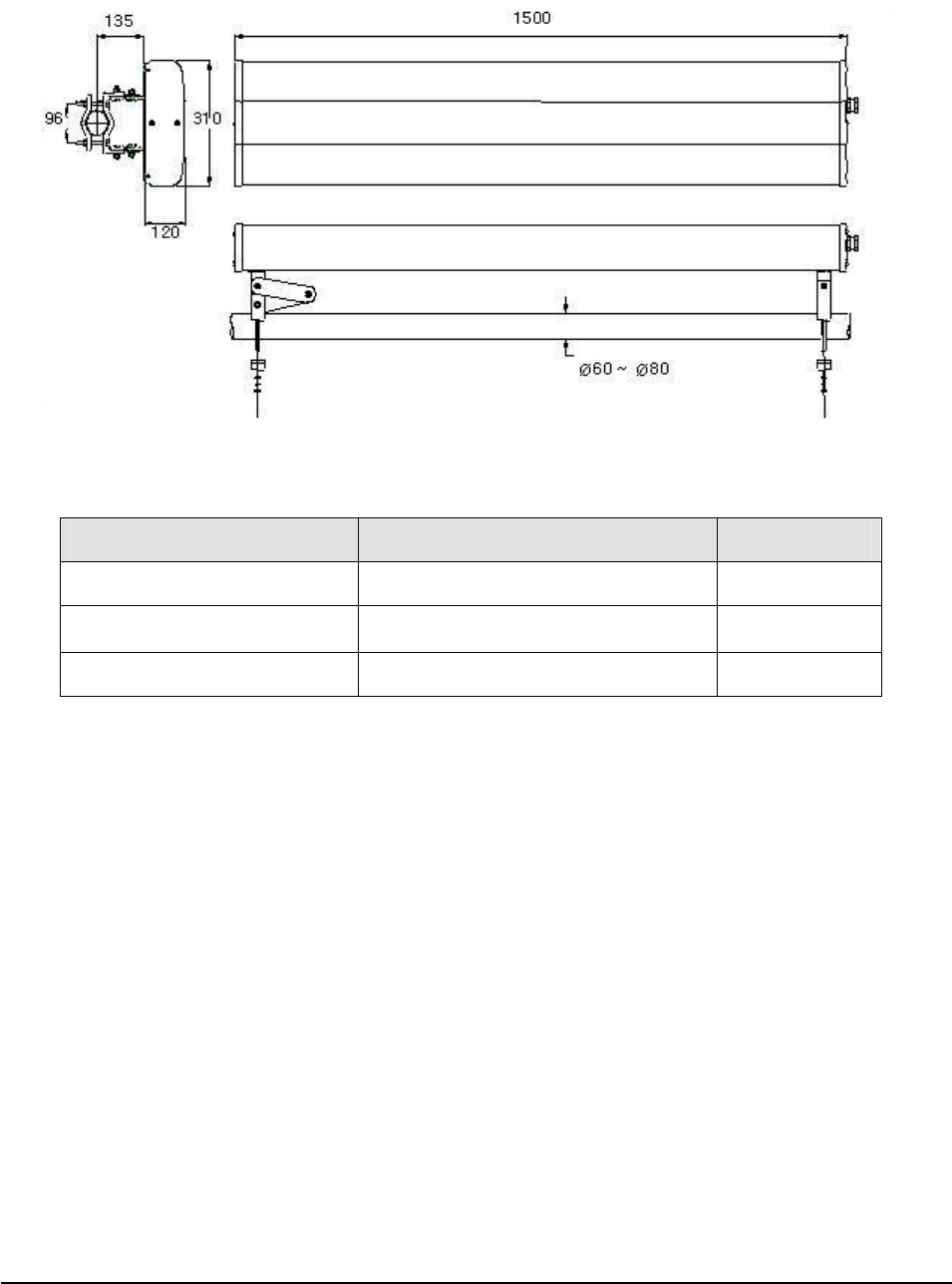
2.2.2 Distributor Antenna
[Figure 2
[Figure 2[Figure 2
[Figure 2-
--
-4] Distributor antenna
4] Distributor antenna4] Distributor antenna
4] Distributor antenna
Item Specification Remarks
RF connector 7/16” DIN-female
Size 310(W)1500(D)120(H) mm
Weight Less than 17kg
13/39
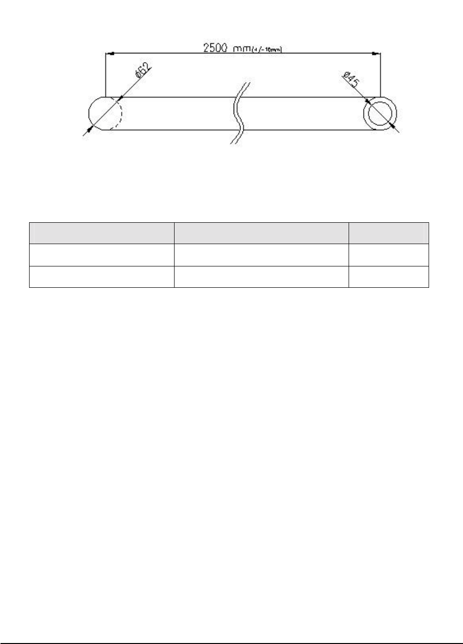
2.2.3 Mount Pole
[Figure 2
[Figure 2[Figure 2
[Figure 2-
--
-5] Mount pole
5] Mount pole5] Mount pole
5] Mount pole
Item Specification Remarks
Length 2500 mm
Weight Less than 6kg

14/39
3.
3.3.
3.
I
II
Installation
nstallationnstallation
nstallation
3.1 General
3.1.1 Overview
This standard provides a reasonable and efficient installation method for the NOTCHCELL repeater in
consideration of site conditions and particularity of the installation process.
3.1.2 Structure
Technical specifications: Description on the configuration and standard for Repeater (Main Box,
PSU Box) specifications and Antenna (Donor antenna, Distributor antenna, Mount pole).
Installation of Repeater & Antenna: Description on the installation method of Repeater and
Antenna
3.1.3 Scope of application
This standard presents all sorts of information on the repeater and the installation standard for the
reasonable and efficient construction as well as the smooth process.
This standard presents general technical conditions for power supplies, groundings, and other
execution designs.
This standard presents the installation of equipments, construction and details to be considered
under the site conditions.
All construction works must be performed in conformity to this standard, but are subject to the site
conditions.
3.1.4 Safety management
Objective
ObjectiveObjective
Objective
This safety regulation defines the requirements for eliminating dangerous causes and preventing
accidents in workers’ conducting their duties at the site.
Scope of application
Scope of application Scope of application
Scope of application
Site representatives, safety managers or site supervisors are responsible for safety of the site workers
and the public. They shall take the full measures to prevent possible accidents.

15/39
General
GeneralGeneral
General
1) Each and every worker is responsible in the end for his/her own safety. He/she shall observe the
safety regulations, and shall receive clear direction from the site representative for any special
cases not specified in the safety regulations.
2) Safety training and preliminary actions shall be taken before the work.
3) Supervisors shall explain the process and the precautions, and assure that the workers understand
the followings.
Purpose and scope of the work
Duty of each worker
Procedure and method of the work
4) Precautions
All workers must secure the safety first and carry out the construction in observance of the safety
regulations.
All workers must progress the construction in orderly and scrupulous manner in consideration of
work process and situation.
Do not drink, smoke, act imprudently or make jokes during the work.
Make clear signals during the work.
Be careful not to fall off from height. And never drop or throw materials or tools.
Each worker shall to his/her duty of safety management, and takes immediate action if any
danger is found.
5) Dress and equipments.
Be sure to wear a safety helmet during the work.
Do not wear slippery shoes.
Do not take off clothes or shoes during the work.
Do not wear gloves while working with a rotary machine.
Do not put in the pockets such tools as knives and screwdrivers.
6) Cautions at work
Check the surroundings of the site, and remove any danger before the work.
Do not force the workers to perform outdoor work in bad weather.
Be prepared with first aid medicine and the plan to contact hospitals in preparation for
unexpected accidents.
In the storage area, make sure of securing emergency passages to exit and of the easy access to
fire fighting equipments.
Keep the material in a safe place in consideration of the maximum weight.

16/39
Installation
Installation Installation
Installation
Pre-examine the danger that may occur during the work.
Make sure of the location of exits and fire fighting equipments.
Observe the non-smoking instruction.
Always keep the work site tidy and clean.
Check the cleaning status, any cause of fire, and locks after the work.
Installing cables
Installing cablesInstalling cables
Installing cables
Do not drag the cables too fast or with excessive force at the installation.
Wind/unwind the cables with enough curvature to prevent damage.
Make a precise connection between the ends of the cables at the installation.
Be careful not to have the cables entangled at the installation or removal of the cables.
When installing the cables over the power cable, be sure to apply insulating cover.
O
OO
Other
therther
thers
ss
s
Fix the ladder firmly when working on it for a long time.
Place warning signs at least 5m before the construction site.
Set the traffic control point at the jammed road.
Do not step or sit on the cables or other breakable facilities during the work.
Be careful not to receive electric shock during the work.

17/39
3.2 Installing information
3.2.1 Installation site
Right
RightRight
Right-
--
-of
ofof
of-
--
-way
wayway
way
The repeater shall be installed in the location owned or leased by the carrier.
If the repeater is installed on the roof, spaces for the installation must be considered.
Conditions for the Installation space
Conditions for the Installation space Conditions for the Installation space
Conditions for the Installation space
Installation of the cabinet requires the following spaces.
1) Roof
Do not install the cabinet near heavy equipments or water tanks for load distribution.
Establishes the Cabinet in order for the good air circulation of the rear side.
Make sure there is a passage for the equipments to carry the cabinet.
2) Field
Select the installation location on a higher ground level to prevent the cabinet from being
inundated.
Install the cabinet at a distance of at least 5m from the stream or the river.
Make sure there is a passage and parking space for vehicle to carry the cabinet.
Install the cabinet in where there is no obstacle visually and physically.
Make sure to level the slope when installing on a slope in a mountainGUG G
G
Precautions
Precautions Precautions
Precautions
Check the followings before installing the cabinet.
1) Roof
Avoid the location in which any accidental or intentional damage may occur.
Do not install the cabinet on the weak slab.
Do not install the cabinet on the building with the seriously damagedGUG
2) Field
Do not install the cabinet on poor ground, sandy soil, or muddy ground.
Do not install the cabinet in a ditch, river, or frequently flooded area.
Do not install the cabinet on any locations that are easily frozen.
Do not install the cabinet near the road.
Make sure to installation after securing safety facilities if installing it near the road.
Do not install the cabinet in damp and humid areas.
Take proper measures against salt when installing the cabinet in the coastUG G

18/39
Carrying and loading
Carrying and loadingCarrying and loading
Carrying and loading
Be careful not to cause any accident when loading the cabinet or carrying it to the installation site
and not to be damaged when handling it.
To prevent corrosion, carry the cabinet in silver vinyl or a wooden box.
Warning: To prevent all possible damage, do not unpack the box until the cabinet is carried to the
installation location.
Do not load excessive material on the top or cover of the packing.
3.2.2 Installing support
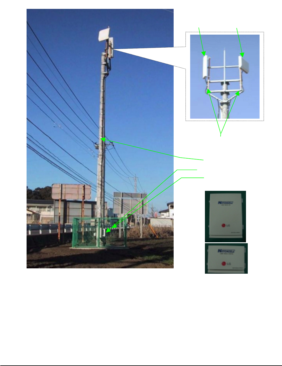
The NOTCHCELL repeater can be installed on a roof, an electric pole, or a large steel tower.
See the standard of the constructor for the installation on the steel tower or the electric pole.
19/39
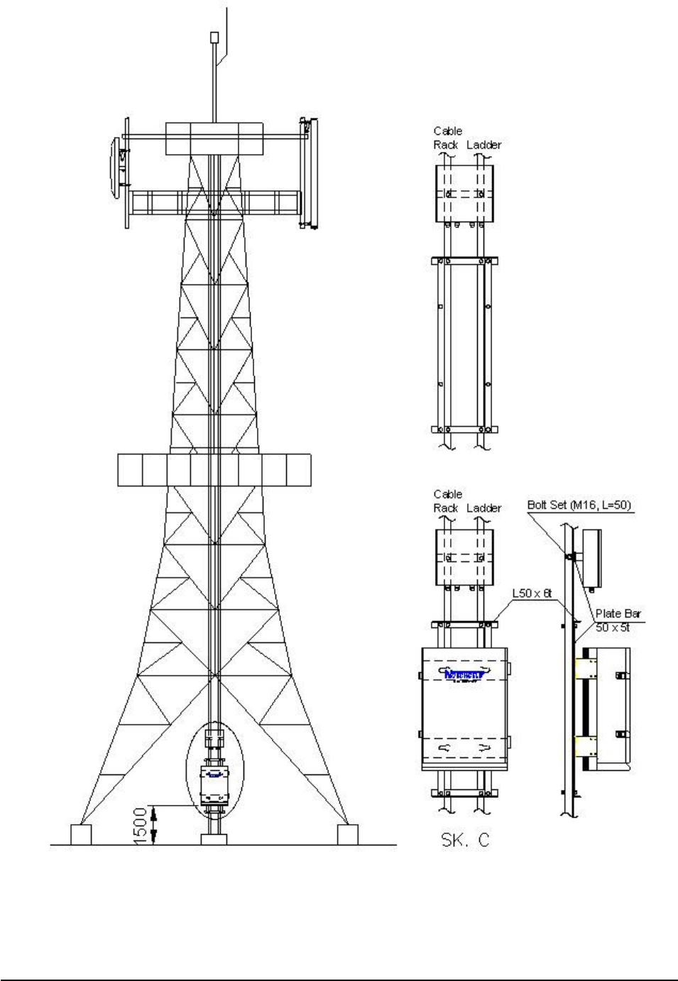
3.3 Installing the repeater & Antenna
The installation methods of the repeater vary depending on the types of support (steel tower), location,
and demand of the carrier. This standard specifies the general supporting methods and is subject to the
types of support.
[Figure 3
[Figure 3[Figure 3
[Figure 3-
--
-1] Definition of
1] Definition of 1] Definition of
1] Definition of assemblies
assembliesassemblies
assemblies (ex. electric pole)
(ex. electric pole) (ex. electric pole)
(ex. electric pole)
Feeder
Main & PSU box
Distributor
Antenna
Mo
unt
Donor
Antenna
Safety facilities

20/39
3.3.1 General
Check the level of ground when installing the repeater.
Check if there is enough space for maintenance.
If required, install branches to secure the safety of the steel tower.
Fasteners must be melted and zinc plated.
Use two nuts for a bolt to prevent the connection from becoming loose.
f the repeater is installed too high, set up the safety scaffoldUG G
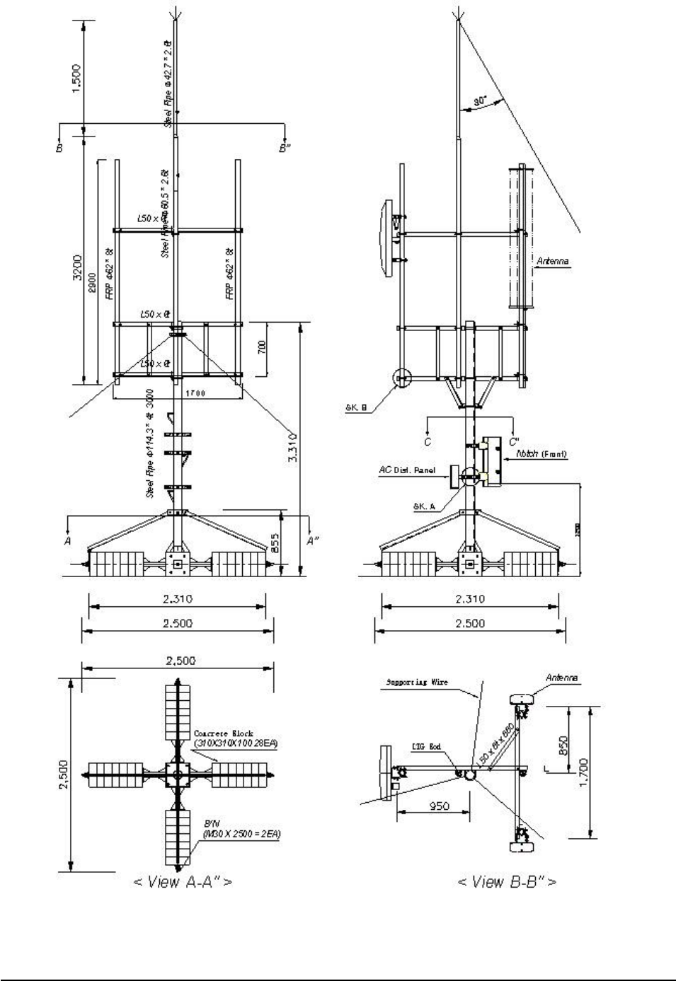
3.3.2 Installing band
When installing the repeater on a cylindrical support such as steel pipe and steel pole, manufacture
and install the band in accordance with the size of the support.
When installing the repeater on the roof, the standard height to the bottom of the repeater shall be
1.2m.
Install the AC distribution panel near the repeater or in the rear of the repeater.
21/39
[Figure 3
[Figure 3[Figure 3
[Figure 3-
--
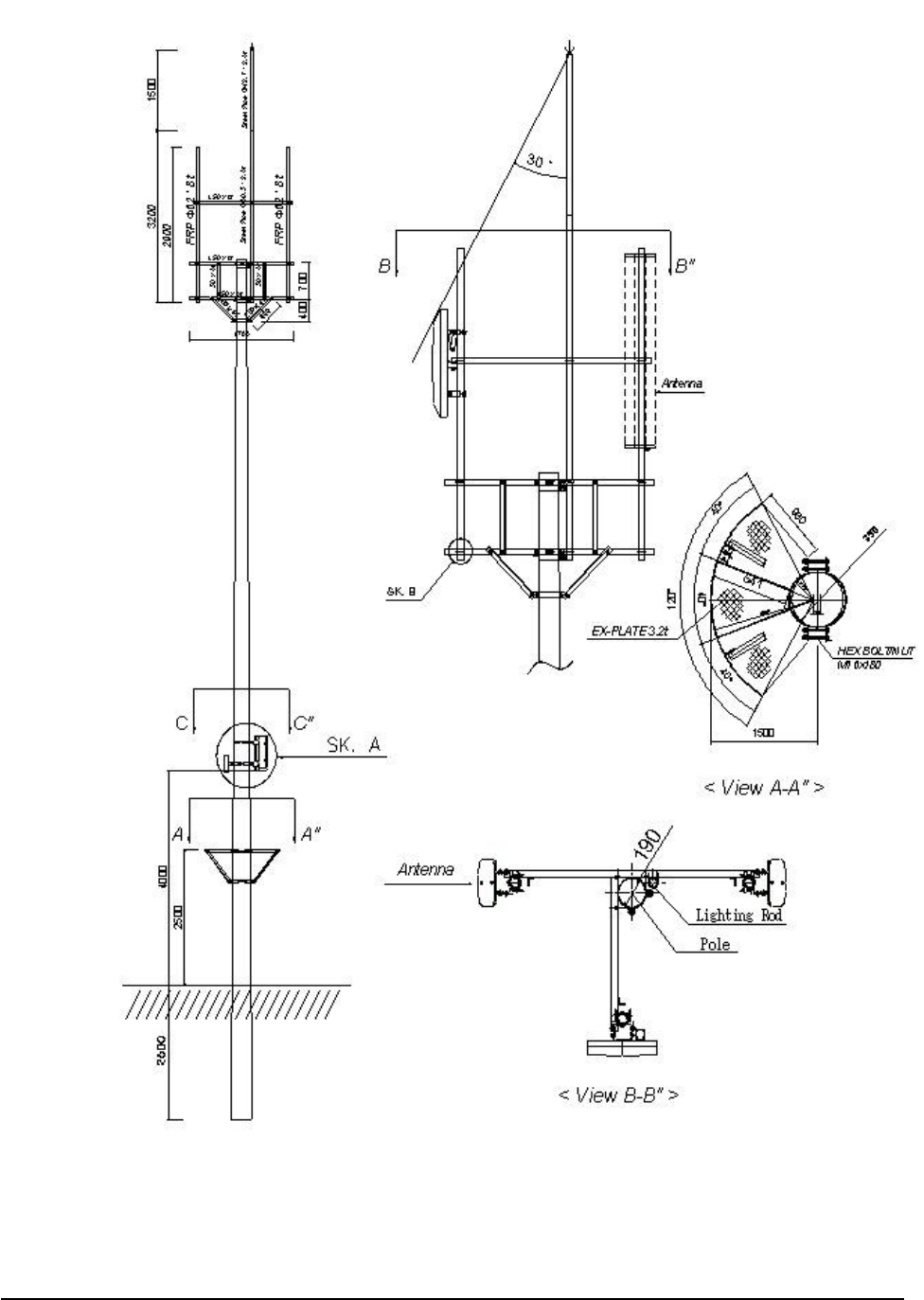
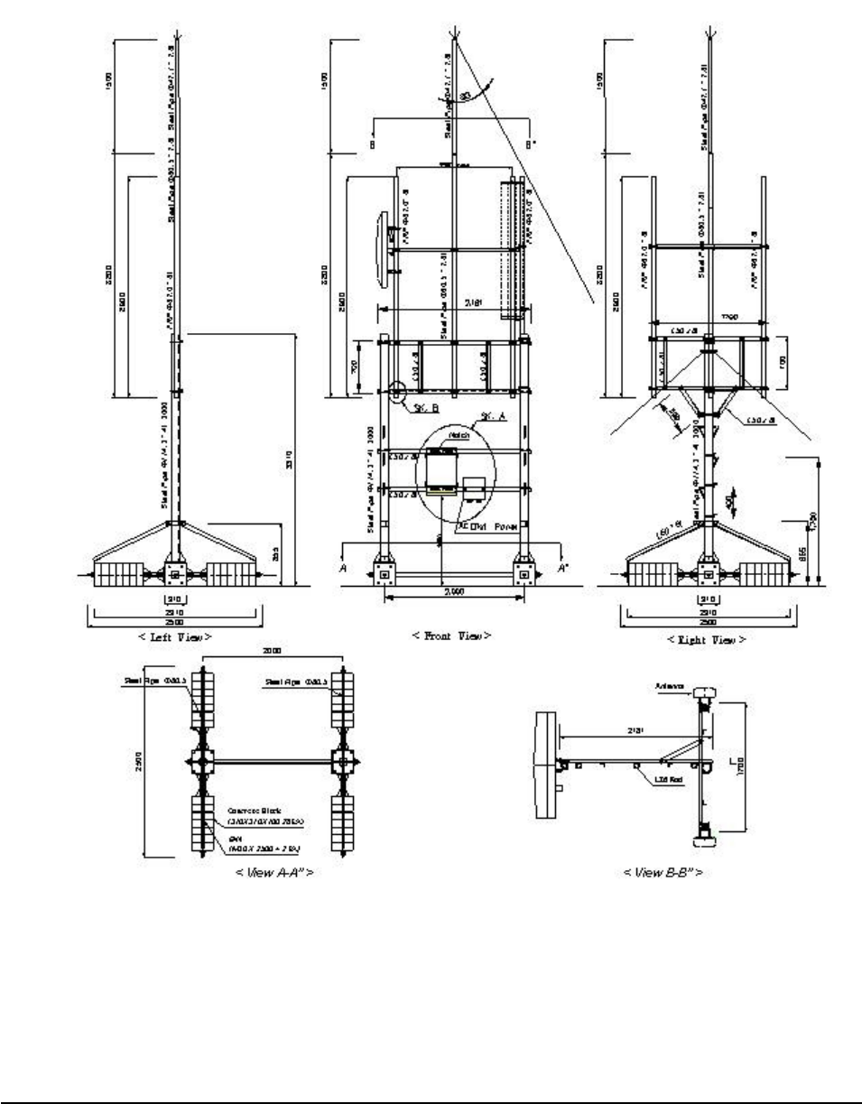
-2] Band installation diagram 1 (steel tower type)
2] Band installation diagram 1 (steel tower type)2] Band installation diagram 1 (steel tower type)
2] Band installation diagram 1 (steel tower type)
22/39
[Figure 3
[Figure 3[Figure 3
[Figure 3-
--
-3] Band installation diagram 2 (
3] Band installation diagram 2 (3] Band installation diagram 2 (
3] Band installation diagram 2 (electric
electricelectric
electric pole type)
pole type) pole type)
pole type)
23/39
[Figure 3
[Figure 3[Figure 3
[Figure 3-
--
-4] Band installation diagram 3
4] Band installation diagram 34] Band installation diagram 3
4] Band installation diagram 3 (location of cabinet)
(location of cabinet) (location of cabinet)
(location of cabinet)
[Figure 3
[Figure 3[Figure 3
[Figure 3-
--
-5] Band set
5] Band set5] Band set
5] Band set
Band Set
24/39
Installing L
Installing LInstalling L
Installing L-
--
-Type angle
Type angleType angle
Type angle
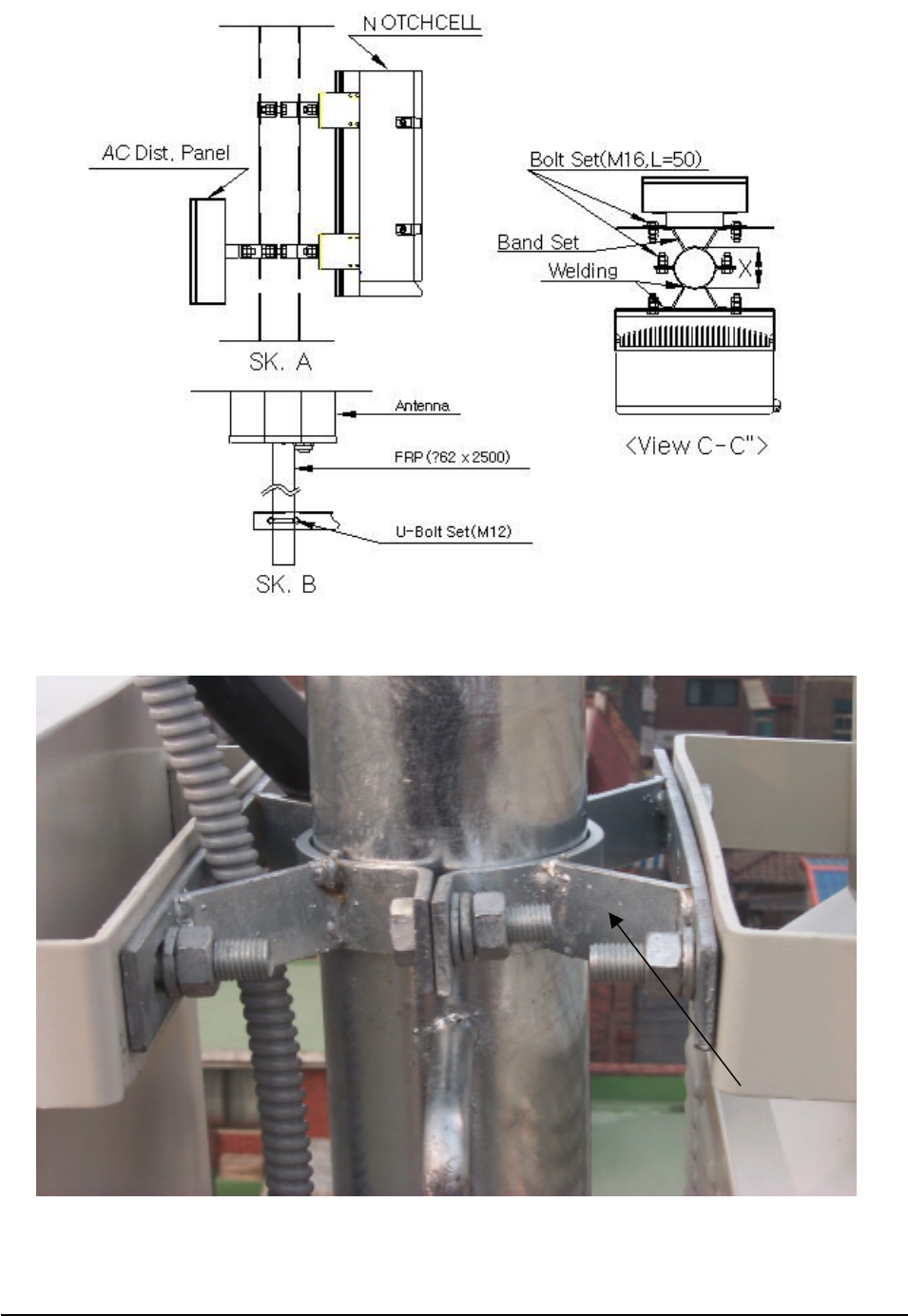
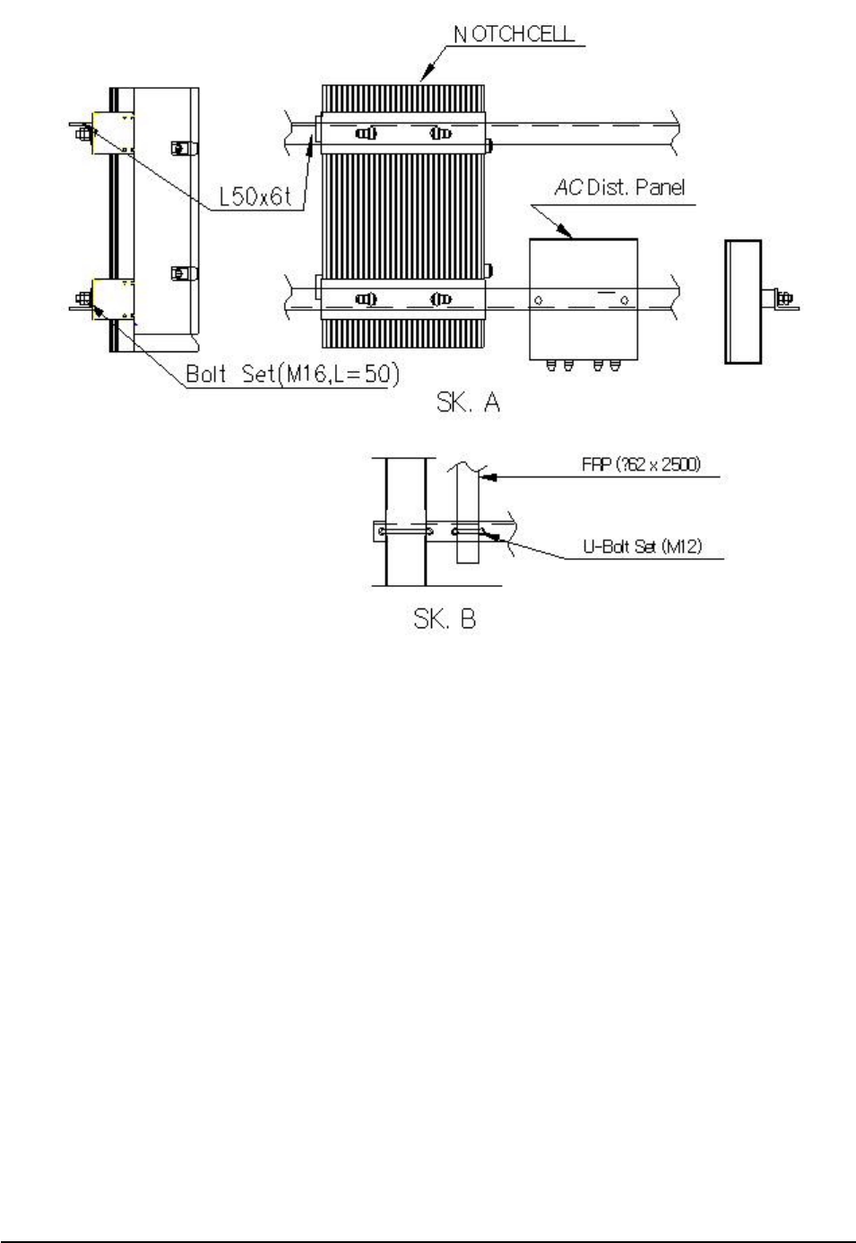
The AC distribution panel shall be, in principle, on the left of the repeater.
When installing the repeater on the roof, the standard height to the bottom of the repeater shall be
1.2m, and 4m when on a field.
[Figure 3
[Figure 3[Figure 3
[Figure 3-
--
-6] L
6] L6] L
6] L-
--
-Type installation diagram 1 (steel tower type)
Type installation diagram 1 (steel tower type)Type installation diagram 1 (steel tower type)
Type installation diagram 1 (steel tower type)
25/39
[Figure 3
[Figure 3[Figure 3
[Figure 3-
--
-7] L
7] L7] L
7] L-
--
-Type installation diagram 2 (location of cabinet)
Type installation diagram 2 (location of cabinet)Type installation diagram 2 (location of cabinet)
Type installation diagram 2 (location of cabinet)
26/39
[Figure 3
[Figure 3[Figure 3
[Figure 3-
--
-8] L
8] L8] L
8] L-
--
-Type installation diagram 3 (steel tower type)
Type installation diagram 3 (steel tower type)Type installation diagram 3 (steel tower type)
Type installation diagram 3 (steel tower type)

27/39
3.3.3 Installing Antenna
Pr
PrPr
Precautions
ecautions ecautions
ecautions
Antenna is a precise material. Make sure of no damage or deformation on it through the careful
installation.
Do not apply excessive force nor work in a hurry.
The retainers shall be zinc plated.
Set the accurate direction of the antenna with the transit when setting up antenna support and its
installation direction.
Select the location where radiating or receiving the radio wave from the antenna is not disturbed by
neighboring buildings or other topographical features or where bad influences can be excluded.
Select the location where the antenna is electrically isolated enough from spurious wave or high
voltage cable that may block the radio wave radiation or reception.
Load generated by the Antenna must be evenly distributed on the steel tower. It must be also
applied on the main material of the steel tower.
Each Antenna supporting bar must be fixed under the safety angle (60ȃ) of lighting rod.
Installing Antenna
Installing Antenna Installing Antenna
Installing Antenna
Fix the Antenna firmly to stand against external impact and wind.
For isolation, FRP (562x2500) shall be used as the Antenna fixing bar.
The Antenna shall be installed at a distance of minimum 1.5m from the Donor Antenna and the
Distributor Antenna.
Fix the Donor and Distributor antenna-fixing bar (FRP) onto at least 3 spots on the steel tower with
the U- Volt
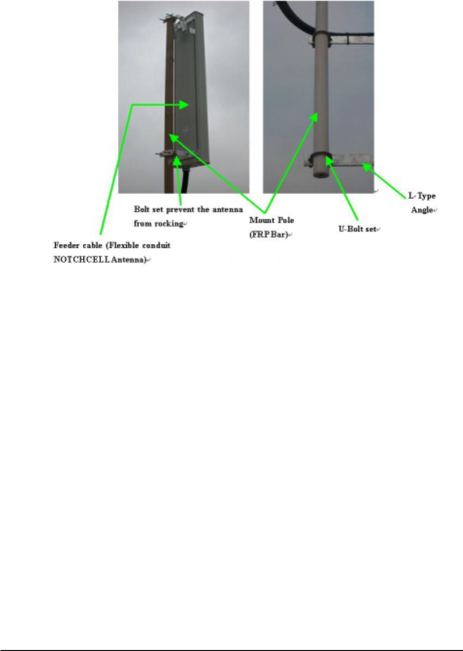
28/39
[Figure 3
[Figure 3[Figure 3
[Figure 3-
--
-9] Antenna Installation
9] Antenna Installation9] Antenna Installation
9] Antenna Installation
29/39
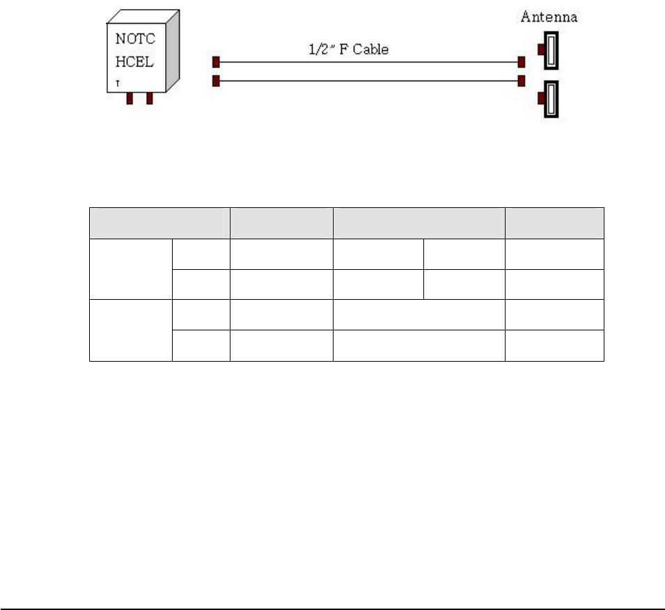
3.3.4 Installing the feeder cable
Installing the feeder cable
Installing the feeder cable Installing the feeder cable
Installing the feeder cable
1) Connection between the antenna and the repeater
Use two NOTCHCELL Antennas.
Install a pair of 1/2” cable from the arrestor on the bottom of the repeater cabinet to the Antenna.
The Standard of feeder cable between the Antenna and the repeater shall be conformed to that of
the carrier.
The Connector for the feeder cable and the connector for the 36mm Flexible Conduit End Cap
are installed on the bottom of the repeater and the NOTCHCELL Antenna.
2) Connecting the feeder cable connector
1/2” feeder cable
[Figure 3
[Figure 3[Figure 3
[Figure 3-
--
-10] 1/2
10] 1/210] 1/2
10] 1/2”
””
”Feeder Cable Diagram
Feeder Cable Diagram Feeder Cable Diagram
Feeder Cable Diagram
[Table 3
[Table 3[Table 3
[Table 3-
--
-1] Example of Connectors for 1/2
1] Example of Connectors for 1/21] Example of Connectors for 1/2
1] Example of Connectors for 1/2”
””
”feeder cable
feeder cable feeder cable
feeder cable
Item ARRESTER 1/2” F Cable Antenna
Type N-Female N-Male Din-Male Din-Female
Connector
Q’ty - 2 2 -
Type - 1/2” F Cable -
Feeder
cable Q’ty - 2 -

30/39
3) Cautions in the installation of the feeder cable
Install the cable in the shortest distance, if possible, between the Antenna and the repeater.
The selected cable path must not affect the appearance of the building or the station.
When installing the repeater in a general building, select the cable path in which the feeder cable
is not damaged by outsiders or other factors.
Select the feeder cable path with less curves and attach the feeder cable tag.
The VSWR in the power feeder must not higher than the standard at the completion of the work.
Do not use the damaged feeder cable.
4) Installing/ tying the feeder cable
The installation of the feeder cable is sensitive to the bend radius and humidity.
Therefore, the following regulations shall be observed.
Maintain the minimum bend radius. (Higher than the standard presented by the manufacturers)
he cable must not be entangled.
Do not apply excessive force to the feeder cable to prevent bent insulated conductors or dug
coverings.
The outer connecting part of the connector must be waterproof.
Tie the cable at every 50cm.
Tie the cables firmly so that they shall not be affected by external impact.
Use the bending machine if required to bend the cable.
Cut the feeder cable with a hacksaw and clean out the cut area.
5) Feeder cable connector
The followings shall be observed at the assembly of the feeder cable connector.
Cut the feeder cable carefully to prevent the inflow of water, steel and lead strip, or dust.
Clean the connector and the gasket connector to keep airtight.
Do not apply excessive force nor work in a hurry.
Avoid connection work at the time of rain. If it is unavoidable, be careful to prevent the inflow of
rain to the connecting part of the feeder cable connector.
Install the 1/2” feeder cable by inserting it into the shield cable and 36mm flexible conduit. In
case of the 7/8”feeder cable, install the cable only.
The installation of the 1/2” feeder cable is as follows
Cut the 1/2”feeder cable, Shield cable and 38mm Flexible Conduit in a necessary length.
Insert 1/2”feeder cable into the Shield cable, and then assemble the connectors at both ends.
Compress the Shield cable on the Antenna side with the Heat Shrink Tube.
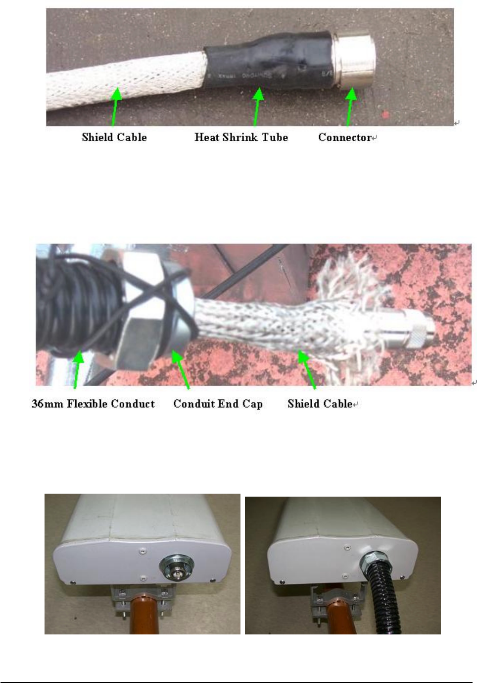
31/39
[Figure 3
[Figure 3[Figure 3
[Figure 3-
--
-11] Shield Cable and Connector
11] Shield Cable and Connector11] Shield Cable and Connector
11] Shield Cable and Connector
Assemble the Conduit End Cap (repeater accessory) at both ends of 36mm Flexible Conduit.
Insert the assembled 1/2” feeder cable (shield cable) into the 36mm Flexible Conduit.
[Figure 3
[Figure 3[Figure 3
[Figure 3-
--
-12] Feeder Cable at Repeater Side
12] Feeder Cable at Repeater Side12] Feeder Cable at Repeater Side
12] Feeder Cable at Repeater Side
After installing and tying the cable, connect the connector to the bottom of the antenna and then apply
the Conduit End Cap.
[Figure 3
[Figure 3[Figure 3
[Figure 3-
--
-13] Connector on the Antenna Side
13] Connector on the Antenna Side13] Connector on the Antenna Side
13] Connector on the Antenna Side
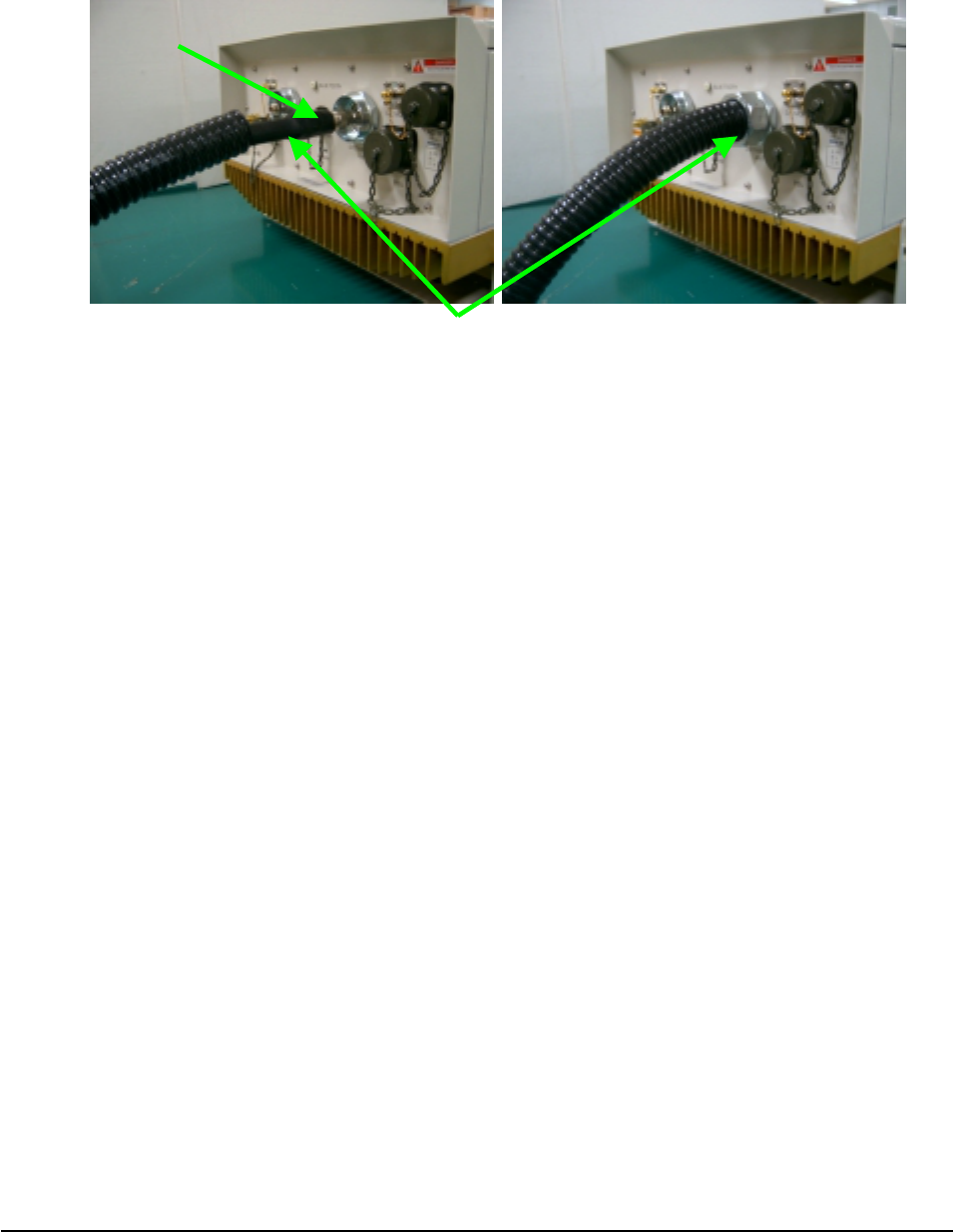
32/39
Compress the Shield cable on the repeater with the heat shrink tube.
Connect the feeder cable connector to the arrestor onto the bottom of the repeater, and then apply the
Conduit End Cap.
[Figure 3
[Figure 3[Figure 3
[Figure 3-
--
-14] Installing the connector on the repeater side
14] Installing the connector on the repeater side 14] Installing the connector on the repeater side
14] Installing the connector on the repeater side
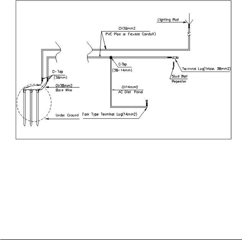
3.3.5 Grounding
Three types of grounding are applied - system grounding, arrester grounding, and steel tower
grounding.
The arrester and the fixing studs are installed on the bottom of the repeater.
The steel tower grounding and arrester grounding shall be in conformity to the standard of the steel
tower manufacturer.
General
GeneralGeneral
General
Use the GV cable for the grounding.
Branch point shall be finished with C-tap and the heat shrink tube. When branching off outside,
make sure to prevent the inflow of rain.
Grounding shall be, in principle, connected from the Under Ground grounding.
Install the grounding cable with PVC Flexile Pipe and Flexible Conduits for the external protection.
Connector
Conduit End Ca
p
33/39
System grounding
System groundingSystem grounding
System grounding
The Under Ground shall be made with up to 3 ground bars or with ground resistance of 20Ω or
lower.
After excavating the ground to 70Cm from the surface, cast the ground bars at a distance of at least
3m between one another.
Connect the ground bars to the PVC Pipe with Bare Wire(38շ) and C-Tap.
Connect GV 38շ x 1C to the stud on the bottom of the cabinet with the underground bar.
Use the 1 Hole Terminal Lugs, and finish with the Green Shrink Tube.
For the arrester grounding of the steel tower, connect GV 38mm² x 1C from the Under Ground
[
[[
[Figure
FigureFigure
Figure 3
3 3
3-
--
-15]
15]15]
15] Ground Cable Diagra
Ground Cable Diagra Ground Cable Diagra
Ground Cable Diagram
mm
m
AC distribution panel grounding
AC distribution panel groundingAC distribution panel grounding
AC distribution panel grounding
For Surge Protector ground of the AC distribution panel, connect GV 14շ cable to the repeater cabinet
grounding cable (GV 38շ), branching it off with C-Tap (38-14mm).
Connect to the ground Terminal Block in the AC distribution panel with the Fork Type Terminal Lug.
34/39
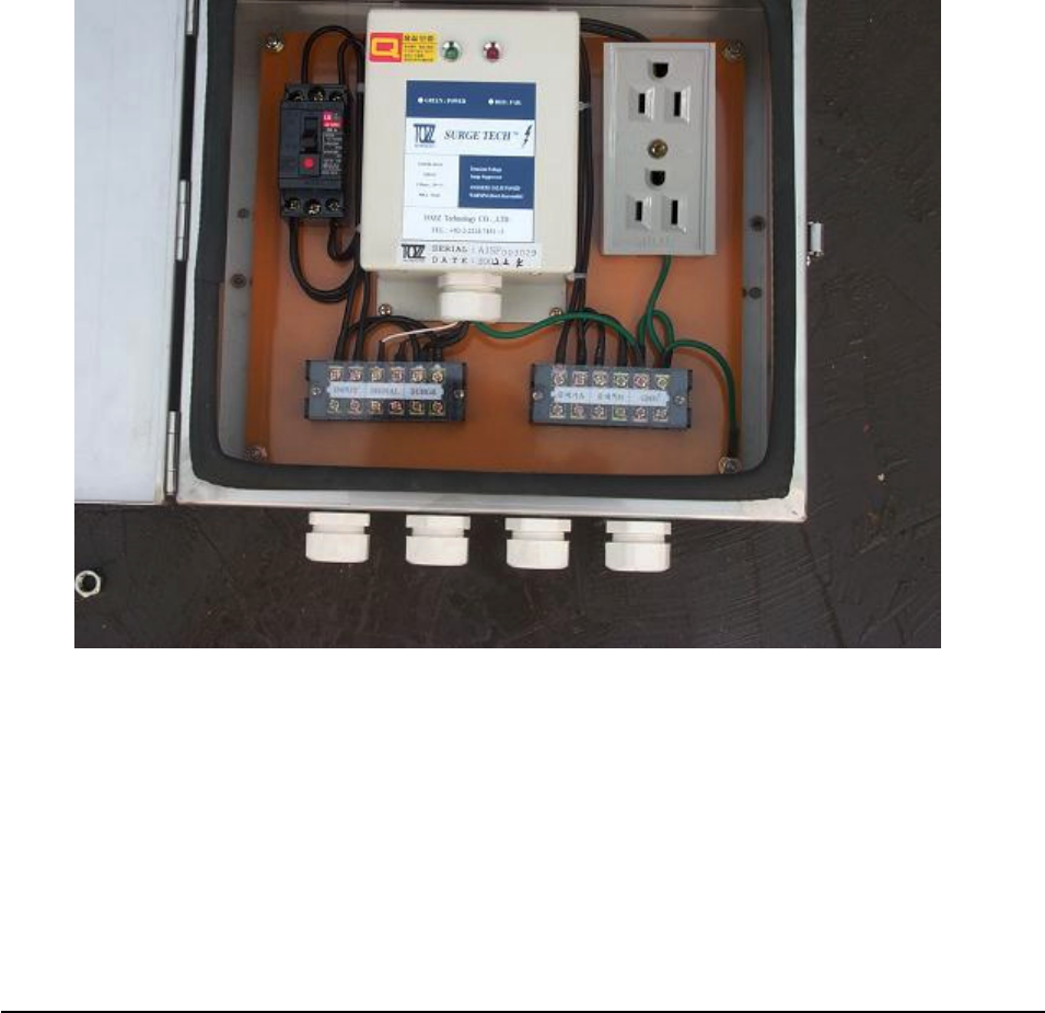
3.3.6 Installing AC power cable
AC distribution panel
AC distribution panel AC distribution panel
AC distribution panel
Install the AC distribution panel on the steel tower to supply AC power to PSU Box.
1) AC distribution panel specification
The AC distribution panel consists of a Breaker (30A), a Surge-Protector (40KA),
a two - hole outlet, and terminal blocks.
The cabinet shall be waterproof and equipped with cable bushings on the bottom.
[
[[
[Figure
FigureFigure
Figure 3
3 3
3-
--
-16]
16]16]
16] AC Distribution Panel Diagram
AC Distribution Panel Diagram AC Distribution Panel Diagram
AC Distribution Panel Diagram
35/39
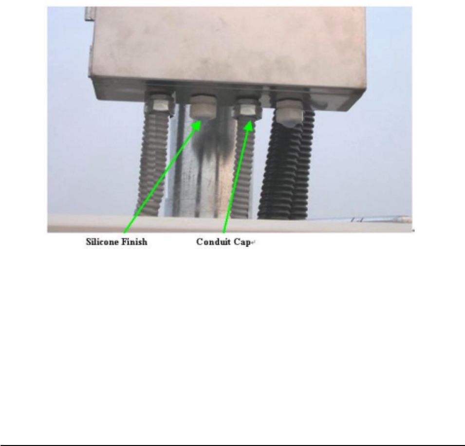
Installing AC power cable
Installing AC power cable Installing AC power cable
Installing AC power cable
Connect the CV 5.5շ ~ CV 22շ x 2C power cable from the accumulative wattmeter to the AC
distribution panel with the Ring Type Terminal Lugs and Flexible Conduits.
Use the Fork Type Terminal Lugs when connecting the AC power cable.
No cable will have contact points inside the conduit, and distribution/connection shall be allowed
only in the AC distribution panel.
Use 22mm flexible conduit when installing the power cable.
Fix the conduit firmly on the wall or the ground with Saddle.
Fill up the vacant cable busing holes on the AC distribution panel with silicon.
Fit the end of the flexible conduits with the conduit caps or by taping.
All the Flexible Conduits must be sealed tight.
[
[[
[Figure
FigureFigure
Figure 3
3 3
3-
--
-17]
17]17]
17] Flexible Conduit End Fitting
Flexible Conduit End Fitting Flexible Conduit End Fitting
Flexible Conduit End Fitting
36/39
4.
4.4.
4.
Operatio
OperatioOperatio
Operation
nn
n
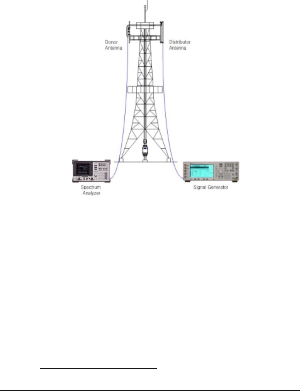
4.1 Isolation test procedure of Antenna
[Figure 4
[Figure 4[Figure 4
[Figure 4-
--
-1] Isolation test
1] Isolation test1] Isolation test
1] Isolation test
1) Set-up the equipment as shown in [Figure 4-1] Isolation test
2) Set up the analyzer for the highest possible sensitivity (more than 100dBm) for 0dBm source-
power.
3) Set the analyzer to ‘peak search mode’.
4) After calibrated cable loss between Measurement Equip and Antenna, set the output-power of the
generator to 0 dBm.
5) Turn on Signal Generator Output
6) Measure the Antenna Isolation, using spectrum analyzer. The minimum isolation is the highest
value of the curve (excepting carriers transmitted by surrounding BS).
7) Change measurement-ports to check for the opposite direction by repeating the measurement
procedure.
8) Repeat the test for the opposite path of the repeater. Step (1) to (7).
Isolation per carrier frequency is worse value.

37/39
4.1.1 Power-up sequence
1) Confirm whether LGE NOTCHCELL Repeater was linked normally with Donor Antenna and
Distributor Antenna or not.
2) Confirm whether Main box and PSU box's AC input and DC connection cable were connected
normally.
3) Turn AC input switch of PSU Box interior on.
4) Confirm whether various LED (AC Fail, DC Fail, and BATT . Fail)s of PSU box interior are
normally. (Normal: Yellow, abnormal: RED)
Only, BATT. Fail LED does normal action in following condition.
PSU box's DC IN Connector has to be linked to Battery.
BATT . Switch has to be established by ON.
5) Confirm state of ARCU board's POWER, RUN, WNMC, GUI, OPERATING LED of Main box
interior.
6) POWER: When +5V is powered ARCU board, Yellow LED is lighted.
7) RUN: When ARCU board's CPU acts normally, Yellow LED twinkles.
8) WNMC: When send and reveive Data between ARCU and ARIU's Modem, Red LED twinkles.
9) GUI: When receive Data from ARCU board in monitoring PC, Yellow LED twinkles.
10) OPERATING: Orange LED twinkles by 1 second cycle after normal booting of ARCU board.
4.1.2 Repeater control application
1) Execute LGE NOTCHCELL's Local GUI program "SPCS gui.exe".
2) Connect Local OMT port and PC's data communication port using communication cable (MS 10SL
_3 pin to D-sub _9 pin type).
3) After Local GUI does Loging, confirm whether data communication between Repeater and PC is
normal.
4) Confirm whether Downlink path's RSSI satisfies dynamic range (- 55dBm ~ - 30dBm).
5) When set Downlink path’s maximum output and maximum gains, consider and decide RSSI and
antenna isolation.
Also, Repeater's maximum gains establishment considers 15 dBs Margin in isolation of antenna.
Repeater’s maximum gain = Antenna isolation – 15dB (Margin)
6) After decide Downlink path's output and gains according to user's request, do DL PA toggle switch
enable in Local GUI's control window.
7) When inspect Downlink path's output waveform, inspect using Monitoring port (SMA-Female
type) on Main box’s right side lower column.

38/39
8) When set Uplink path’s maximum output and maximum gains, consider and decide RSSI and
antenna isolation.
Also, Repeater's maximum gains establishment considers 15 dBs Margin in isolation of antenna.
Repeater’s maximum gain = Antenna isolation – 15dB (Margin)
But, in the case of Uplink path, when set output and gains because it is no fixed input level, set on
the basis of Noise level.
Up Link Gain = 113 [dBm]
+ BS_ Noise Level [dBm]
– Repeater_Feeder cable loss [dB]
– Donor ant. Gain [dBd]
– Path Loss [dB]
– BS_Ant. Gain [dBd]
– BS_Feeder cable loss [dB]
Air Loss (dB) = 20log (1/λ) + 20log (4π) + 20log (d)
Only, preceding formula recommands to apply in Line of site section of BS and Repeater.
However, can be different from noise level and theoretical arithmetic level by change of RF
environment.
9) When inspect Uplink path's output waveform, inspect using Monitoring port (SMA-Female type)
on Main box’s left side lower column.
10) In Local GUI's control window, consider site situation about items below and establish properly.
Parameters to act Alram that correspond to each input/output
Parameters to act ALC function
Parameters to act Shutdown function
11) After input each setting value in Local GUI's control window, moving by monitor window, confirm
alarm's existence and nonexistence.
12) Erase alarm that happen at setup process in Local GUI's History window.
39/39
NOTCHCELL
Operation Manual
Copyright © 2003 LG Electronics Inc.
All Rights Reserved
Copyright of this manual belongs to LG Electronics.
Reproduction, distribution or revision of part or all of
contents in this manual in any form without written
permission of LG Electronics, Inc. is prohibited.
The information in this manual is subject to change for the reason of
function improvement, design alteration, etc. without any prior
notification.
http://isupport.lge.co.kr
C