LG Electronics USA RU50PY10 Plasma Display Panel User Manual 479Hen
LG Electronics USA Plasma Display Panel 479Hen
UserManual.wiki
>
LG Electronics USA
>
RU50PY10 User Manual
>
Users Manual Part 1
Contents
1.
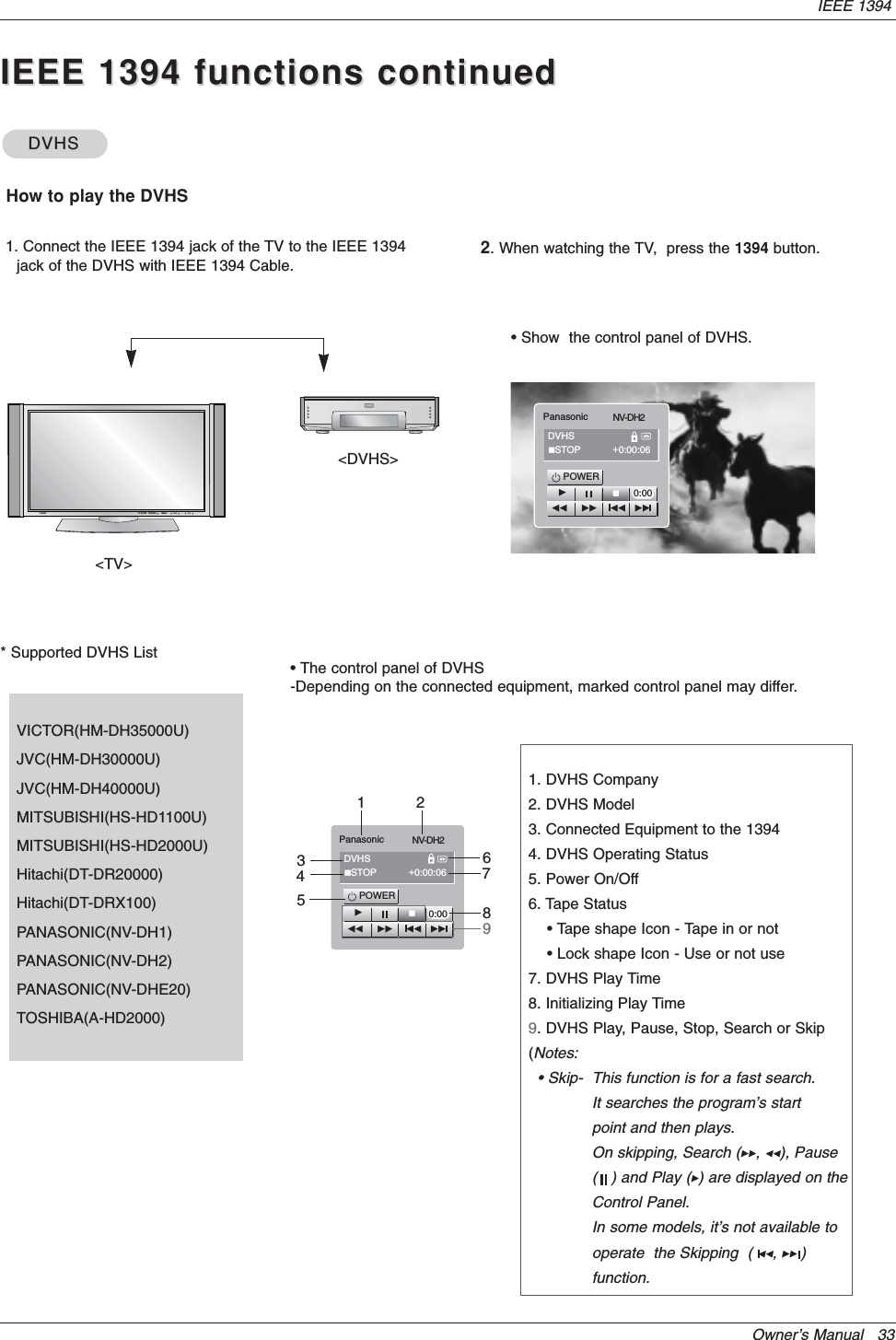
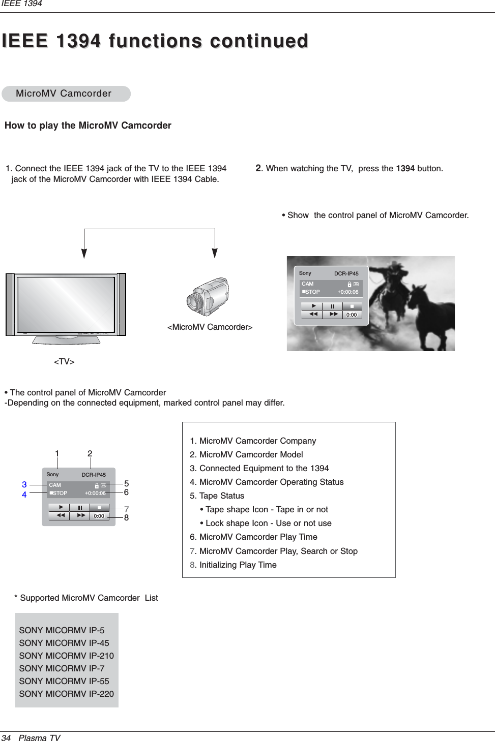
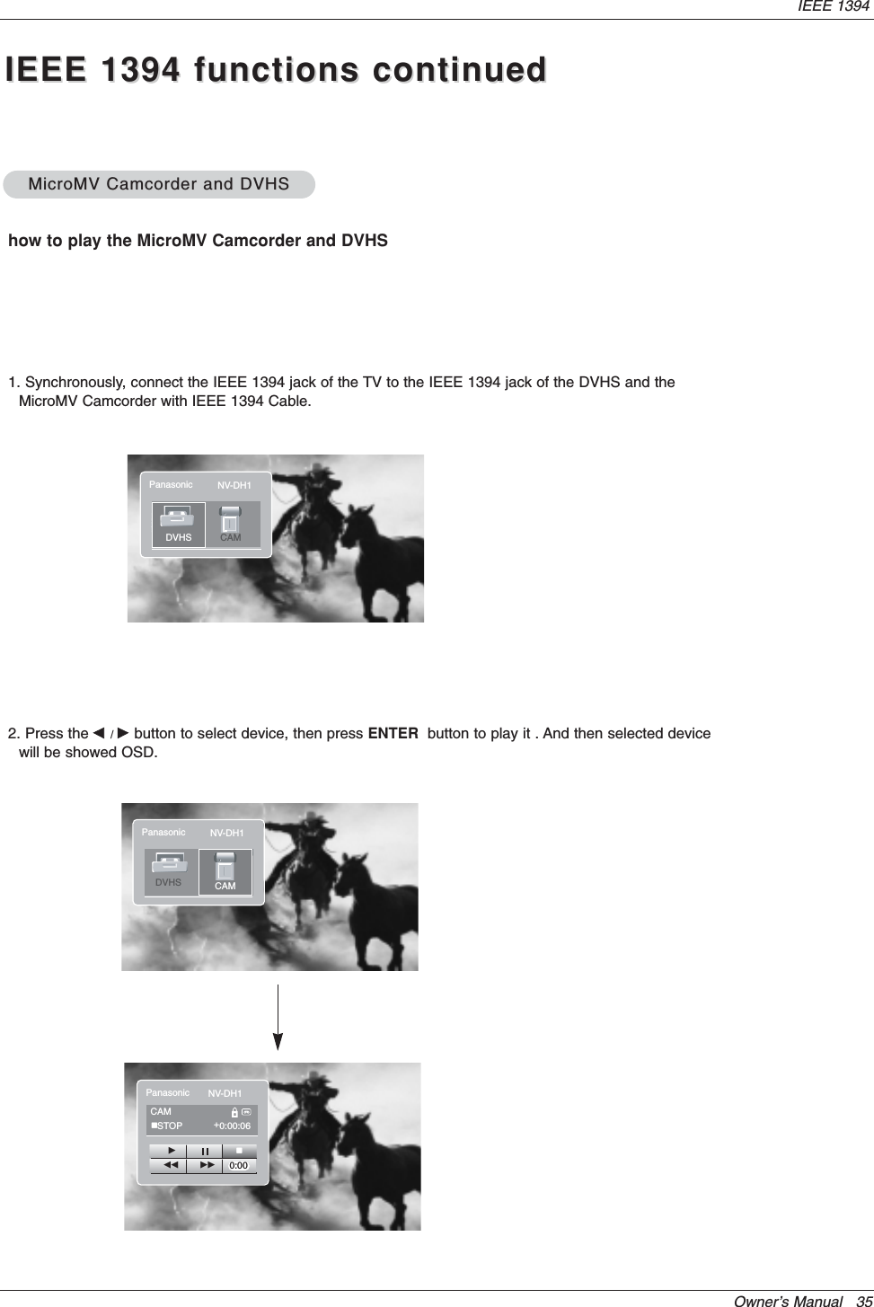
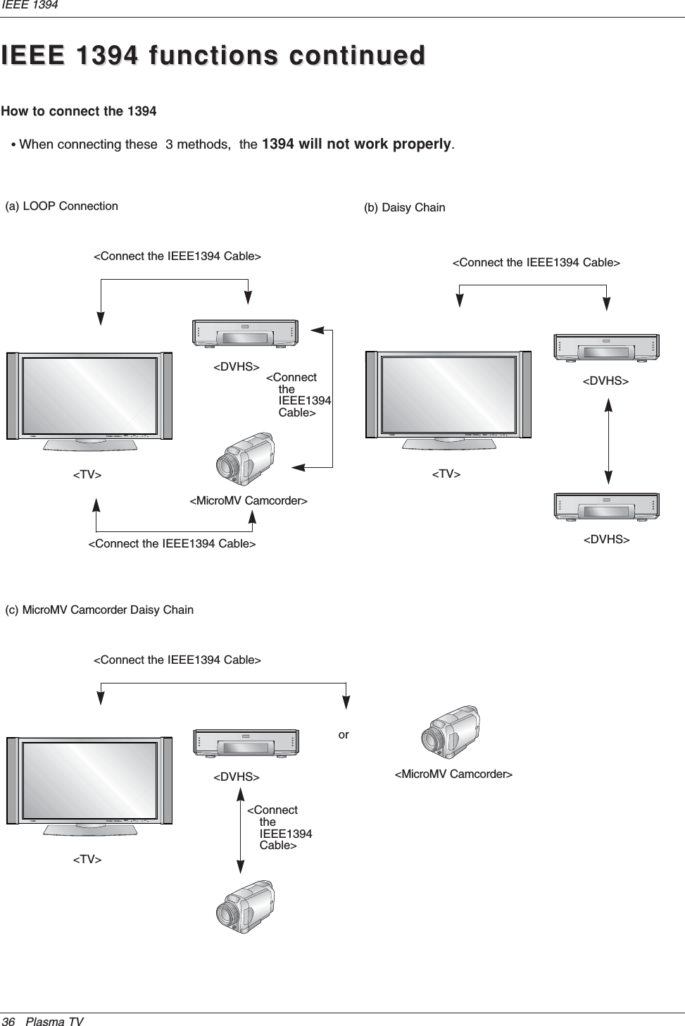
Users Manual Part 1
2.
User Manual Part 2
Users Manual Part 1
Navigation menu
Upload a User Manual
Namespaces
Wiki Guide
HTML
PDF
Info
Views
User Manual
Discussion / Help
Navigation