LG Electronics USA WB3012 WiFi module User Manual EMISSION TEST REPORT
LG Electronics USA WiFi module EMISSION TEST REPORT
user manual

Order Number
: GETEC-C1-12-252
FCC Part 15 subpart C
Test Report Number
: GETEC-E3-12-089
Page 1 / 1
EUT Type: WiFi module
FCC ID.: BEJWB3012
APPENDIX G
: USER’S MANUAL

Aug. 01, 2012
[Wi-Fi Network Controller Module]
Copyright © LG Electronics. All Rights Reserved.
1
HWM-300
Wi-Fi Network Controller Module
User Manual
Contact Us
Tel. :
Weekday: AM 10 : 00 ~ PM 5 : 00
(Customer support time could be change, according to company’s circumstances)
Homepage :
Location :
LG Electronics

Aug. 01, 2012
[Wi-Fi Network Controller Module]
Copyright © LG Electronics. All Rights Reserved.
2
Document Revision History
Date
Revision
Changes

Aug. 01, 2012
[Wi-Fi Network Controller Module]
Copyright © LG Electronics. All Rights Reserved.
3
Table of Contents
1 System Descriptions..........................................................................................................................................6
1.1 Applications ...............................................................................................................................................6
1.2 Module Summary .....................................................................................................................................6
1.3 Block Diagram ……………......................................................................................................................6
2 Mechanical Specifications.................................................................................................................................7
2. 1 Module dimension.....................................................................................................................................7
2.2 Module Pin-out …............................................................................................................................ .........7
3 DC Electrical Specifications….........................................................................................................................7
3.1 Typical Power Consumption…..................................................................................................................7
4 RF Specifications ….......................................................................................................................................8
4.1 RF Characteristics for IEEE 802.11b…....................................................................................................8
4.2 RF Characteristics for IEEE 802.11g …....................................................................................................9
5 Environmental Specifications…........................................................................................................................9
5.1 Absolute maximum ratings …..................................................................................................................9
5.2 Recommended Operating Conditions…..................................................................................................10
6 TELNET or HyperTerminal…......................................................................................................................10
6.1 Demonstration and Test ….......................................................................................................................10
7 Serial Configuration......................................................................................................................................13
7.1 Serial Command …................................................................................................................................13
7.2 Demonstration and Test ….......................................................................................................................13
8 RoHS Declaration............................................................................................................................................14
※ FCC Notice.........................................................................................................................................................14

Aug. 01, 2012
[Wi-Fi Network Controller Module]
Copyright © LG Electronics. All Rights Reserved.
4
Figures
Figure 1. HWM-300-L BLOCK DIAGRAM………………...........................................................................6
Figure 2. HWM-300 Dimensions (unit : mm)..................................................................................................7
Figure 3. HWM-300 module Communication Port settings..........................................................................10
Figure 4. Serial Terminal Program configuration...........................................................................................11
Figure 5. Network Terminal Program configuration......................................................................................12
Figure 6. Received Data by Network Terminal Program...............................................................................12
Figure 7. Serial to Wireless LAN configuration.............................................................................................12

Aug. 01, 2012
[Wi-Fi Network Controller Module]
Copyright © LG Electronics. All Rights Reserved.
5
Tables
Table 1. Interface Connector PIN Assignment.................................................................................................7
Table 2. Typical Power Consumption...............................................................................................................7
Table 3. RF Characteristics for IEEE 802.11b.................................................................................................8
Table 4. RF Characteristics for IEEE 802.11g.................................................................................................9
Table 5. Absolute Maximum Rating................................................................................................................9
Table 6. Recommended Operating Conditions...............................................................................................10
Aug. 01, 2012
[Wi-Fi Network Controller Module]
Copyright © LG Electronics. All Rights Reserved.
6
1 System Descriptions
1.1 Applications
HWM-300 is a complete low power self-contained embedded wireless solution to address
the connectivity demand in M2M applications. It integrates micro-controller, Wi-Fi
BB/MAC/RF IC, RF front end, clocks, and on-board antenna into a small form factor module.
HWM-300 can be controlled by a host device through a serial interface; it can also serve as a
stand-alone Wi-Fi station or network controller. Thus, it can be used to enable wireless
connectivity to the simplest products with minimal engineering resources.
The HWM-300 provides standard IEEE802.11 b/g functions. The integrated CPU supports
software. It can be used for a variety of different applications, such as wireless sensor node,
serial to Wi-Fi transceiver, Wi-Fi network controller, Wi-Fi gateway/bridges plus internet
server.
When used in a system where the HWM-300 is controlled by a host CPU, the serial host
interface makes it very easy to integrate. When used in a system without a host CPU, the
integrated ARM9 CRUNOS can be used to run a variety of applications.
1.2 Module Summary
• 2.4GHz IEEE 802.11b/g radio technology
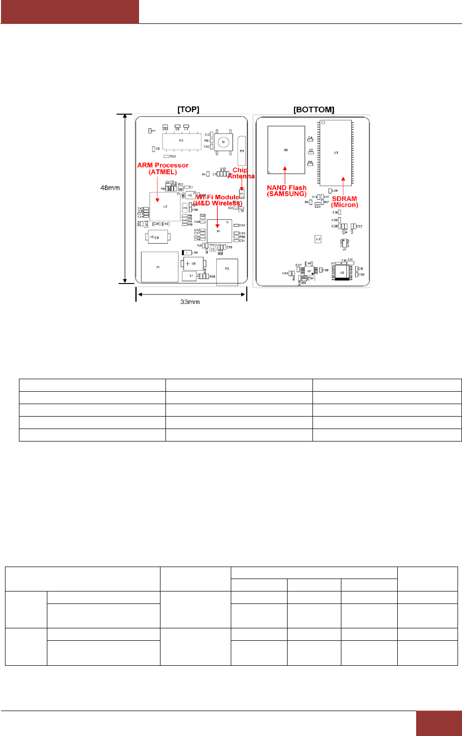
• Dimension: 33 mm × 48 mm × 1.2 mm
• On-board antenna
• Transmit power: +17 dBm @ 11b /11Mbps
• Max receive sensitivity: -92dBm
• CPU: ARM9 CRUNOS
• Diverse serial interface: UART
• Operating temperature range: -30ºC to 85ºC
• RoHS compliant
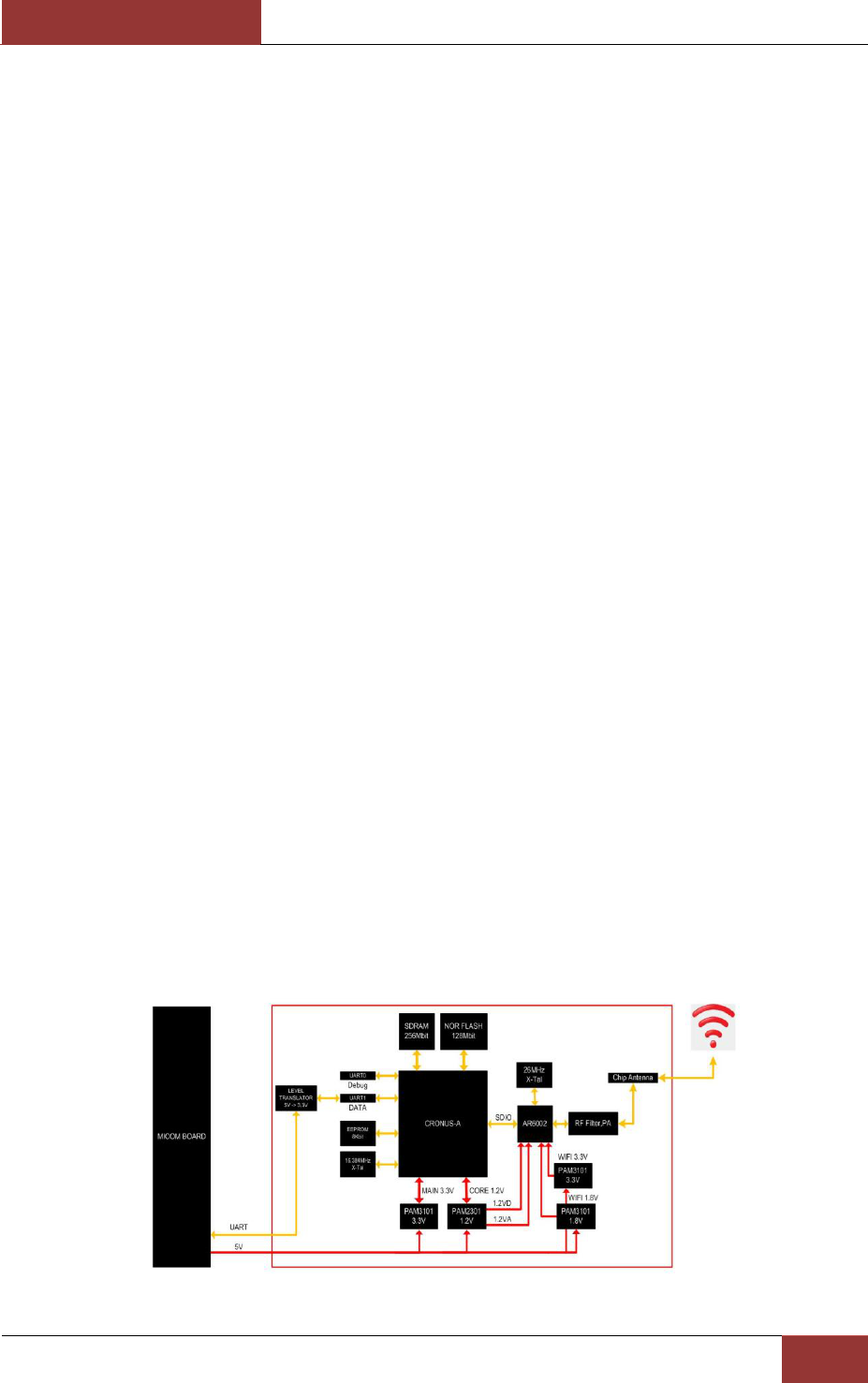
1.3 Block Diagram
Figure 1. HWM-300-L BLOCK DIAGRAM
Aug. 01, 2012
[Wi-Fi Network Controller Module]
Copyright © LG Electronics. All Rights Reserved.
7
2 Mechanical Specifications
2.1 Module dimension
Figure 2. HWM-300 Dimensions (unit : mm)
2.2 Module Pin-out
No
Pin Name
Descriptions
1
5V
Input Voltage
2
TX
UART TX DATA
3
RX
UART RX DATA
4
GND
Ground
Table 1. Interface Connector PIN Assignment
3 DC Electrical Specifications
3.1 Typical Power Consumption
Condition: 25C, includes both Wi-Fi chip and microcontroller
Item
Condition
Values
Units
Min
Typ
Max
11b
Receive mode
11Mbps
-
77
-
mA
Transmit mode
(17dBm/100% Duty Cycle)
-
300
-
mA
11g
Receive mode
54Mbps
-
77
-
mA
Transmit mode
(15dBm/100% Duty Cycle)
-
237
-
mA
Table 2. Typical Power Consumption
Aug. 01, 2012
[Wi-Fi Network Controller Module]
Copyright © LG Electronics. All Rights Reserved.
8
4 RF Specifications
Items
Contents
Technology
IEEE 802.11b/g, WiFi compliant
Frequency
2.4 ~ 2.4835 GHz (US/Canada/Europe)
2.4 ~ 2.497 GHz (Japan)
Modulation Technology
DSSS, CCK, OFDM
Modulation Type
DBPSK, DQPSK, CCK, BPSK, QPSK, 16QAM, 64QAM
Network Access Modes
Access Point, Infrastructure
Channels
USA/Canada: 11 channels
Europe: 13 channels
France: 7 channels
Japan: 14 channels (13 channels for 802.11g)
Wireless Data Rate
802.11b = 11, 5.5, 2, 1 Mbps
802.11g = 54, 48, 36, 24, 18, 12, 9, 6 Mbps
MAC
CSMA/CA with ACK, RTS, CTS
Network Protocols
TCP/IP, ARP, ICMP, DHCP, DHS, UDAP, TFTP, UDP,
PING
Security Protocols
Disabled, WEP 64 & 128bit, WPA (TKIP), WPA (AES),
WPA2 (AES), 802.1x (EAP) Supplicant
802.11I, WPA & WPA2 Enterprise supplicants (EAP-TLS,
EAP-TTLS(MSCHAPv2),
EAPTTLS(MDS5), EAP-PEAPv0(MSCHAPv2, LEAP),
EAP-FAST, LEAP)
Supports Certificates and Private Key Upload and Storage
(Multiple)
*Enterprise and EAP available in client mode only
Antenna
coaxial connectors, 50 ohms
4.1 DC/RF Characteristics for IEEE 802.11b
Conditions: 25deg.C, VDD_WIFI_IN=5V, VDD= 3.3V (11Mbps mode unless otherwise
specified.) Measured at 50Ω terminal load connected to the RF Pad
Items
Contents
Min.
Typ.
Max.
unit
Tx Power Levels 1Mbps
17
18
20
dBm
Tx Power Levels 11Mbps
17
18
20
dBm
Tx Spectrum Mask Fc ± 11MHz
-40
-30
dBr
Tx Spectrum Mask Fc ± 20MHz
-54
-50
dBr
Tx RF Carrier Suppression
-15
dB
Tx Modulation Accuracy(EVM)
17
35
%
Tx OBW(Occupied Bandwidth)
20
MHz
Rx Minimum input Level Sensitivity 1Mbps
(FER≤8%)
-92
-80
dBm
Rx Minimum input Level Sensitivity 11Mbps
(FER≤8%)
-87
-85
-76
dBm
Rx Maximum Input Level (FER≤8%)
-10
dBm
Table 3. RF Characteristics for IEEE 802.11b
Aug. 01, 2012
[Wi-Fi Network Controller Module]
Copyright © LG Electronics. All Rights Reserved.
9
4.2 DC/RF Characteristics for IEEE 802.11g
Conditions: 25deg.C, VDD_WIFI_IN=5V, VDD= 3.3V (54Mbps mode unless otherwise
specified.) Measured at 50Ω terminal load connected to the RF Pad
Items
Contents
Min.
Typ.
Max.
unit
Tx Power Levels 6Mbps
15
16
18
dBm
Tx Power Levels 24Mbps
15
16
18
dBm
Tx Power Levels 54Mbps
13
14
16
dBm
Tx Spectrum Mask Fc ± 11MHz
-34
-20
dBr
Tx Spectrum Mask Fc ± 20MHz
-50
-28
dBr
Tx Spectrum Mask Fc ± 30MHz
-58
-40
dBr
Tx Constellation Error (EVM) 6 Mbps
-30
-5
dB
Tx Constellation Error (EVM) 24 Mbps
-30
-16
dB
Tx Constellation Error (EVM) 54 Mbps
-30
-25
dB
Tx Modulation Accuracy(EVM)
17
35
%
Tx OBW(Occupied Bandwidth)
20
MHz
Rx Minimum input Level Sensitivity 6Mbps
(FER≤10%)
-87
-85
-82
dBm
Rx Minimum input Level Sensitivity 24Mbps
(FER≤10%)
-75
-82
-74
dBm
Rx Minimum input Level Sensitivity 54Mbps
(FER≤10%)
-72
-72
-65
dBm
Rx Maximum Input Level (FER≤10%)
-10
dBm
Table 4. RF Characteristics for IEEE 802.11g
5 Environmental Specifications
5.1 Absolute maximum ratings
Symbol
Description
Min
max
Unit
Top
Operating temperature
-30 8
85
°C
Tst
Storage temperature
-40 8
85
°C
VBAT
Power supply for backup circuitry when
VDD is not present
0
5.0 V
V
VDD_WiFi
Wi-Fi Power supply
0
3.3V
V
RFin
RF input power
0 dB
Bm
RoHS R
Restriction of Hazardous Substances
Compliant
Table 5. Absolute Maximum Rating
Aug. 01, 2012
[Wi-Fi Network Controller Module]
Copyright © LG Electronics. All Rights Reserved.
10
5.2 Recommended Operating Conditions
Parameter
min
typ
max
Unit
VBAT
4.55
5.0
5.5
V
CORE_1.2
1.1
1.2
1.3
V
MAIN_3.3
3.1
3.3
3.5
V
WIFI_1.2
0.9
1.2
1.35
V
WIFI_1.8
1.5
1.8
2.5
V
WIFI_3.3
3.0
3.3
4.0
V
Table 6. Recommended Operating Conditions
6 TELNET or HyperTerminal
You can configure the HWM-300 module by TELNET
STEP1: HWM-300 module with Serial to USB Cable to connect to PC.
STEP2: HWM-300 module connected to the power adapter.
STEP3: Drive Installation and Communication Port settings.
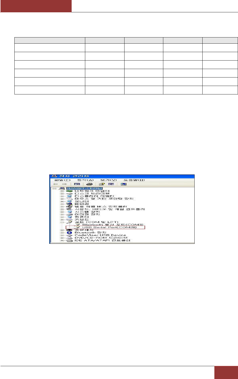
- Port Configuration from the Control Panel - System - Hardware - Device Manager, check.
- Check the USB Serial port assigned.
Figure 3. HWM-300 module Communication Port settings.
STEP4: HWM-300 module and the PC IP address settings.
- HWM-300 module and wireless connection settings.
The HWM-300 module Default SSID is "WLANAP".
- HWM-300 module Default IP address is 192.168.1.254.
Set to the PC IP address to match the IP band 192.168.1.XXX.
6.1. Demonstration and Test
Configure test the functionality of the HWM-300 module.
< Hardware >
The PC equipped with a USB Port
HWM-300 JIG board
Aug. 01, 2012
[Wi-Fi Network Controller Module]
Copyright © LG Electronics. All Rights Reserved.
11
HWM-300 and JIG Board Connecting Cable
PC and connect JIG Board Serial to USB Cable
<Software>
TELNET or HyperTerminal
STEP1.
① PC and connect JIG Board Serial to USB Cable.
② HWM-300 and JIG Board Connecting Cable.
③ DC 5V Adaptor connection.
④ Power switch to the ON.
STEP2.
① PC's “Network Connection → Wireless Network Connection → HWM-300 wireless network
view, select and connect.
② HWM-300 Windows Address window, enter the IP address setting screen is generated Serial
input values. (default:192.168.1.254)
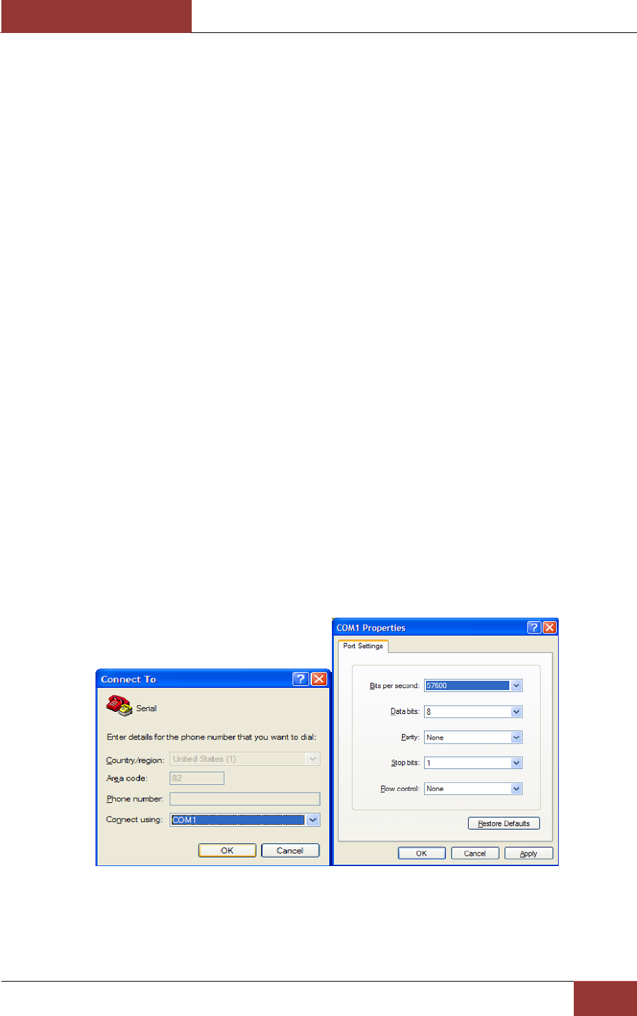
STEP3.
① PC's Hyper Terminal program execution. HWM-300 and the same baud rate as the value of
Setting.
a) Baud Rate : 115200
b) Data : 8 bit
c) Parity : none
d) Stop : 1 bit
e) Flow Control : none
Figure 4. Serial Terminal Program configuration
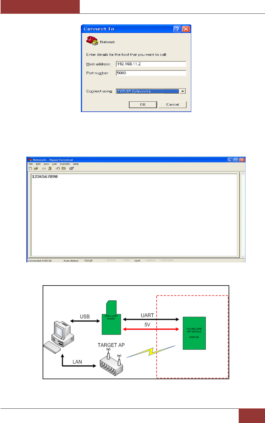
Run the other HyperTerminal, Setting the IP address and Port Number.
Aug. 01, 2012
[Wi-Fi Network Controller Module]
Copyright © LG Electronics. All Rights Reserved.
12
Figure 5. Network Terminal Program configuration
Input serial characters on the HyperTerminal screen. (Sample : “01234567890”) HyperTerminal even on
the characters looks OK.
Figure 6. Received Data by Network Terminal Program
Figure 7. Serial to Wireless LAN configuration

Aug. 01, 2012
[Wi-Fi Network Controller Module]
Copyright © LG Electronics. All Rights Reserved.
13
Network HyperTerminal put words on the same word, the serial data are shown in the HyperTerminal.
7 Serial Configuration
7.1 Serial Command
Using Serial Command HWM-300 AP set. AP Setup mode, the operation mode, access mode. In addition,
Scan, Wireless Controller, that can determine the behavior of the command iwconfig. Command console
window on the screen when you type iwconfig-h command displays the contents.
7.2 Demonstration and Test
The PC is set to the default IP 192.168.120.254, Host behavior when checking ping 192.168.120.254,
because the command Host host to confirm the action. Client behavior when checking the console by
typing ping www.google.co.kr and ping to verify.
<AP operation mode>
#!/bin/sh
#
iwconfig eth1 essid off
sleep 3
killall udhcpc
killall udhcpd
killall httpd
killall wpa_supplicant
iwconfig eth1 mode Master
iwconfig eth1 channel 1
iwconfig eth1 essid 1234567890 # SSID 1234567890, SSID will be required to change.
iwconfig eth1 commit
ifconfig eth1 down
ifconfig eth1 192.168.120.254 # Default IP Address, DO NOT change.
ifconfig eth1 up
sleep 2
httpd -h /root/web1/www
udhcpd &
<AP access mode>
iwconfig eth1 essid off
sleep 3
killall udhcpd
killall udhcpc
killall wpa_supplicant
killall getutctime
killall ndm_daemon
iwconfig eth1 mode Managed
export NETIF=eth1
/root/RUN/image/wmiconfig --startscan --forceScanFlags 0 1 0

Aug. 01, 2012
[Wi-Fi Network Controller Module]
Copyright © LG Electronics. All Rights Reserved.
14
iwconfig eth1 essid 1234567890 # Access SSID
ifconfig eth1 down
ifconfig eth1 up
sleep 2
udhcpc -i eth1 &
8 RoHS Declaration
To the best of our present knowledge, given our supplier declarations, this product does not contain
substances that are banned by Directive ????/???/??? or contain a maximum concentration of 0.1%
by weight in homogeneous materials for
• Lead and lead compounds
• Mercury and mercury compounds
• Chromium (VI)
• PBB (polybrominated biphenyl)
• PBDE (polybrominated biphenyl ether) And a maximum concentration of 0.01% by weight in
homogeneous materials for
• Cadmium and cadmium compounds
FCC Notice
THIS DEVICE COMPLIES WITH PART 15 OF THE FCC RULES.
OPERATION IS SUBJECT TO THE FOLLOWING TWO CONDITIONS:
(1) THIS DEVICE MAY NOT CAUSE HARMFUL INTERFERENCE, AND
(2) THIS DEVICE MUST ACCEPT ANY INTERFERENCE RECEIVED, INCLUDING
INTERFERENCE THAT MAY CAUSE UNDERSIRED OPERATION.
This equipment has been tested and found to comply with the limits for a Class B digital device,
pursuant to part 15 of the FCC Rules These limits are designed to provide reasonable protection against
harmful to part 15 of the FCC Rules. These limits are designed to provide reasonable protection against
harmful interference in a residential installation. This equipment generates, uses and can radiate radio
frequency energy and, if not installed and used in accordance with the instructions, may cause harmful
interference to radio Communication. However, there is no guarantee that interference will not occur in a
particular installation. If this equipment does cause harmful interference to radio or television reception
which can be determined by turning the equipment off and on, the user is encouraged to try to correct the
interference by one or more of the following measures :
- Reorient or relocate the receiving antenna.
- Increase the separation between the equipment and receiver.
- Connect the equipment into an outlet on a oircuit difference from that to which the receiver is
connected.
- Consult the dealer of an experienced radio/TV technician for help.
NOTE : The manufacturer is not responsible for any radio or TV interference caused by unauthorized
modifications to this equipment. Such modifications could void the user's authority to operate the
equipment.
End product labeling
This transmitter module is authorized only for use in device where the antenna may be installed such that
20 cm may be maintained between the antenna and user. The final end product must be labeled in an
visible area with the following “Contain FCC ID: BEJWB3012”. The grantee’s FCC ID can be used only
when all FCC compliance requirements are met.

Aug. 01, 2012
[Wi-Fi Network Controller Module]
Copyright © LG Electronics. All Rights Reserved.
15
IMPORTANT NOTE
(1) Warning that this module is not approved to be operated simultaneously with other radios.
Further certification requirement may required when installed and operated simultaneously with other
radios.
(2) Confirming of approved antenna, and advice that used other type of antenna or same type with higher gain
will required additional certification.