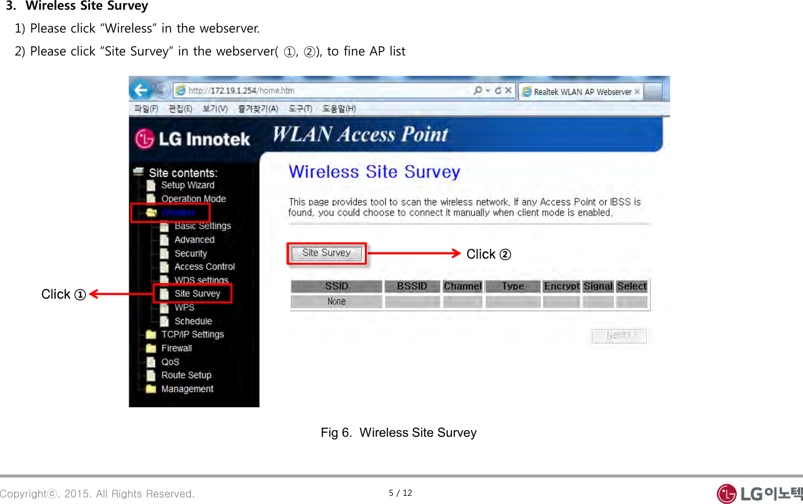
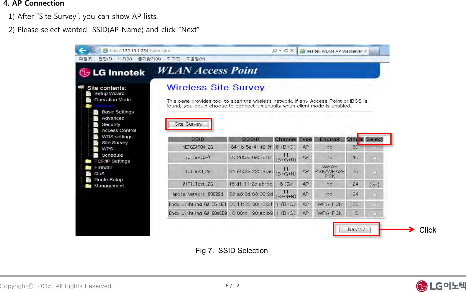
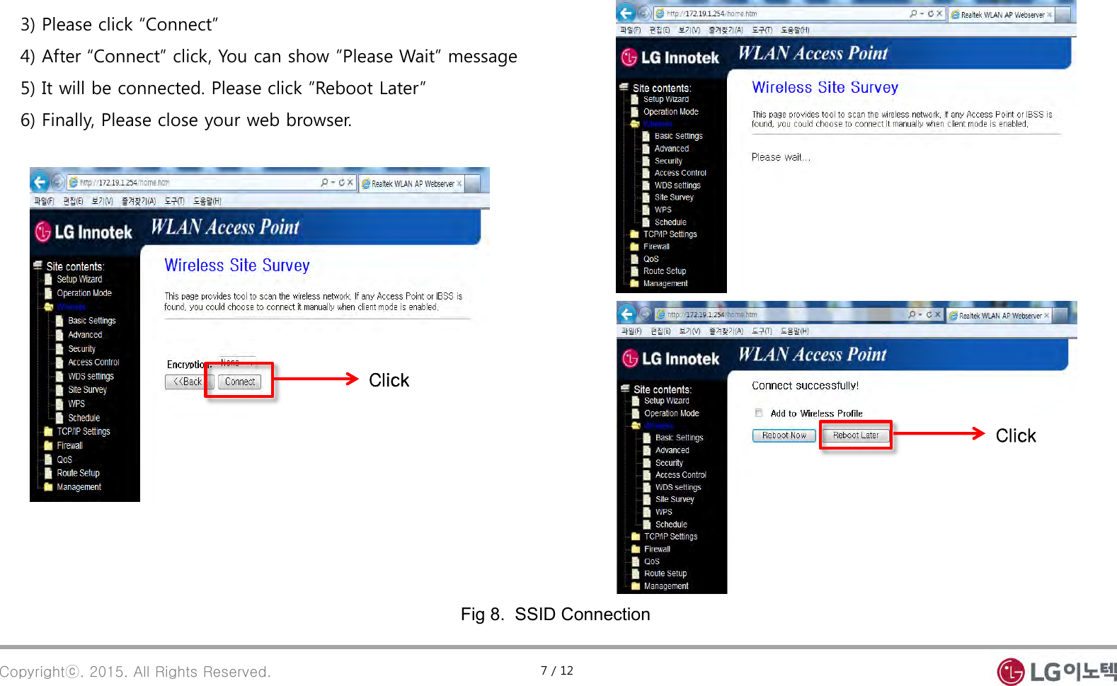
LG Innotek TWFBR101D PoE Wi-Fi Bridge User Manual 1
LG Innotek Co., Ltd. PoE Wi-Fi Bridge 1
UserManual.wiki
>
LG Innotek
>
TWFBR101D User Manual
User Manual
Navigation menu
Upload a User Manual
Namespaces
Wiki Guide
HTML
PDF
Info
Views
User Manual
Discussion / Help
Navigation
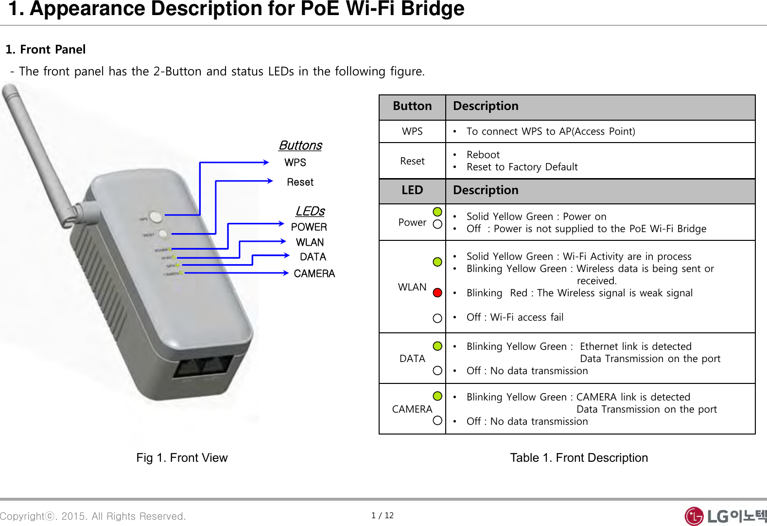
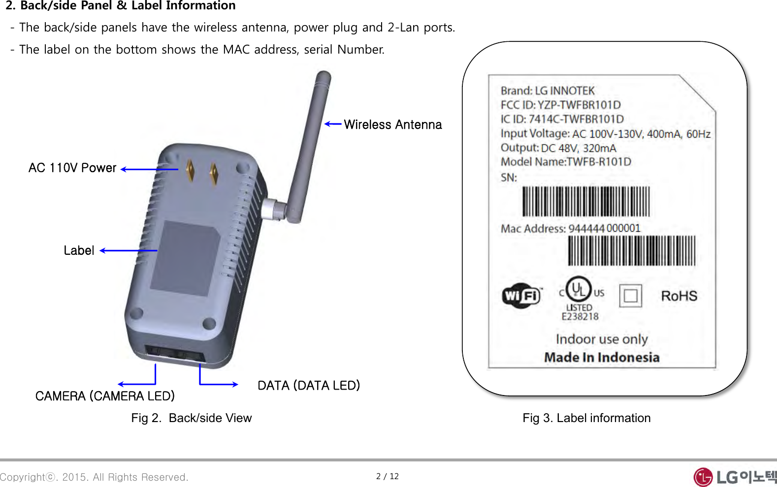
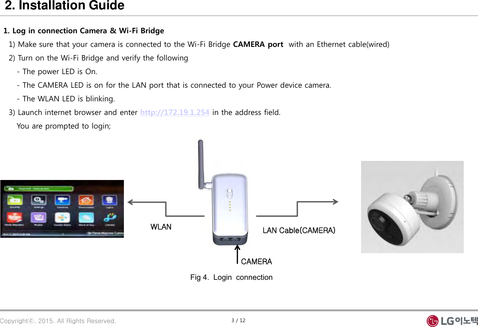
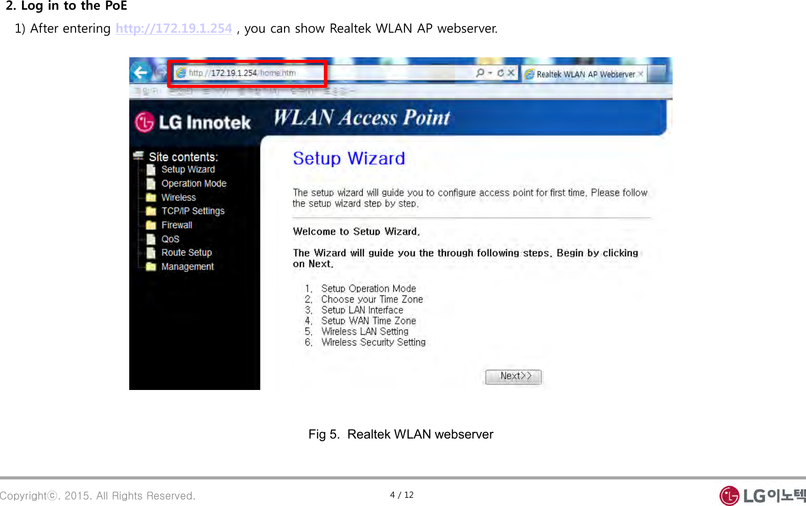
![Inside your life ! . PoE Wi-Fi Bridge Manual (PoE: Power over Ethernet) 2015. 03. 06 [Model Name : TWFB-R101D ]](https://usermanual.wiki/LG-Innotek/TWFBR101D/User-Guide-2564614-Page-1.png)