LG Innotek TWFBR101D PoE Wi-Fi Bridge User Manual 1
LG Innotek Co., Ltd. PoE Wi-Fi Bridge 1
User Manual

Inside your life !
.
PoE Wi-Fi Bridge Manual
(PoE: Power over Ethernet)
2015. 03. 06
[Model Name : TWFB-R101D ]
Copyrightⓒ. 2015. All Rights Reserved.
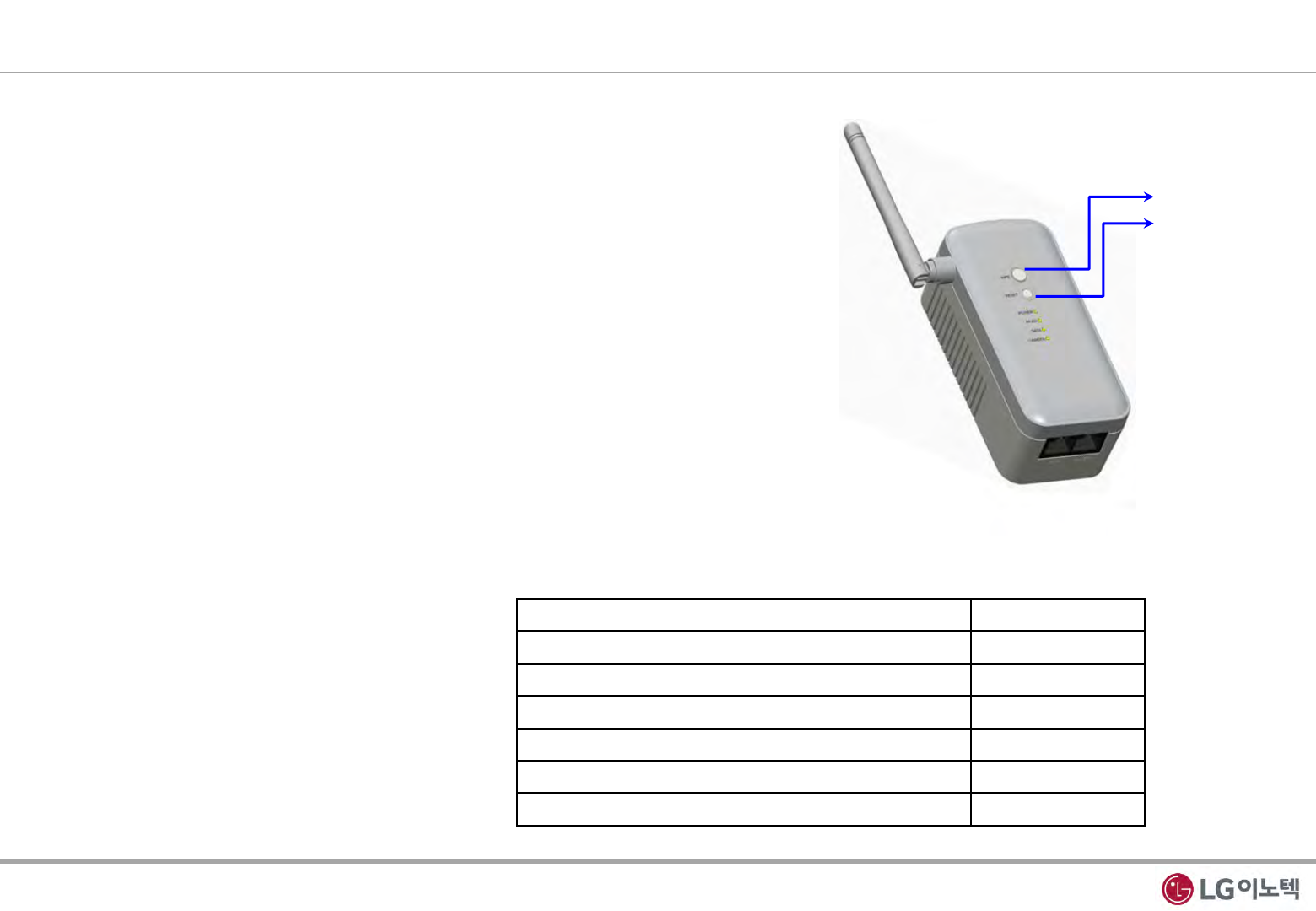
1. Appearance Description for PoE Wi-Fi Bridge
WPS
Reset
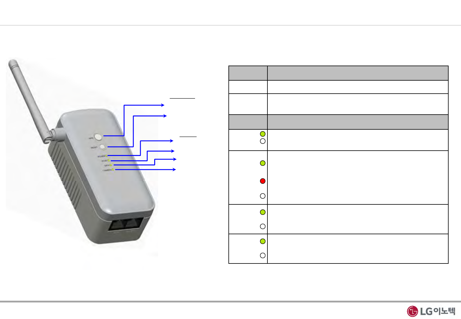
Fig 1. Front View
1. Front Panel
- The front panel has the 2-Button and status LEDs in the following figure.
LEDs
POWER
WLAN
DATA
CAMERA
Buttons
Button Description
WPS •To connect WPS to AP(Access Point)
Reset •Reboot
•Reset to Factory Default
LED Description
Power •Solid Yellow Green : Power on
•Off : Power is not supplied to the PoE Wi-Fi Bridge
WLAN
•Solid Yellow Green : Wi-Fi Activity are in process
•Blinking Yellow Green : Wireless data is being sent or
received.
•Blinking Red : The Wireless signal is weak signal
•Off : Wi-Fi access fail
DATA
•Blinking Yellow Green : Ethernet link is detected
Data Transmission on the port
•Off : No data transmission
CAMERA
•Blinking Yellow Green : CAMERA link is detected
Data Transmission on the port
•Off : No data transmission
Table 1. Front Description
1 / 12
Copyrightⓒ. 2015. All Rights Reserved.
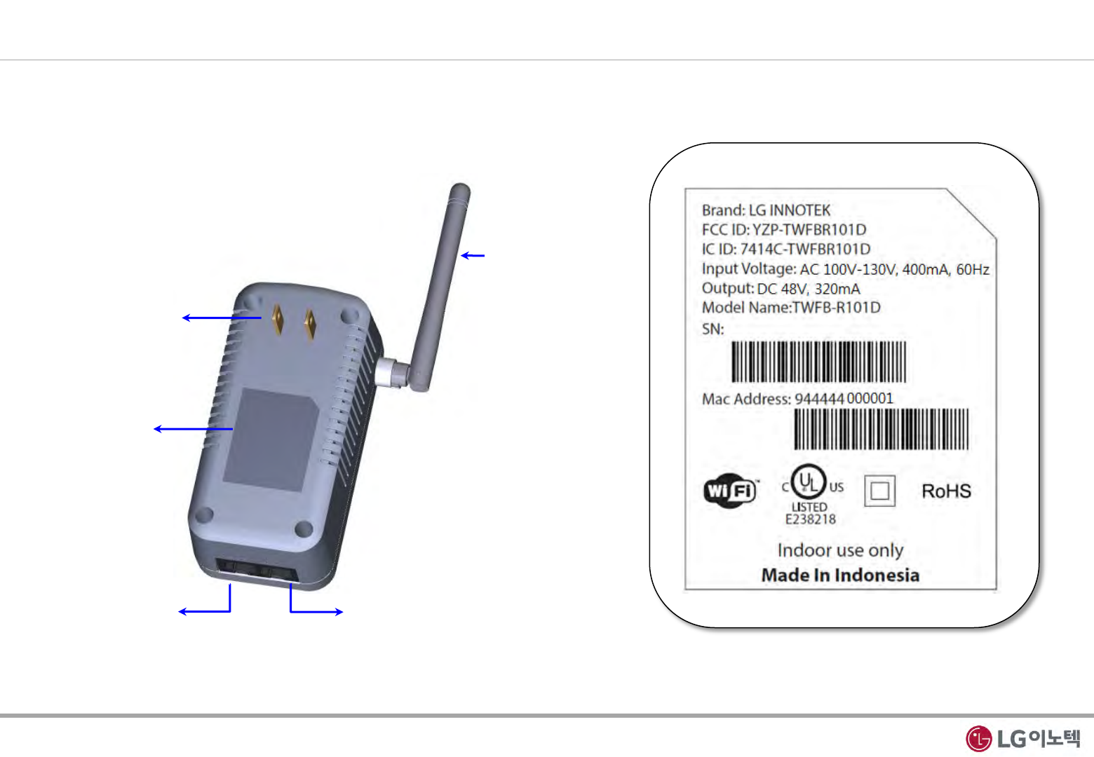
Fig 2. Back/side View
2. Back/side Panel & Label Information
- The back/side panels have the wireless antenna, power plug and 2-Lan ports.
- The label on the bottom shows the MAC address, serial Number.
Fig 3. Label information
DATA (DATA LED)
CAMERA (CAMERA LED)
Wireless Antenna
AC 110V Power
Label
2 / 12
Copyrightⓒ. 2015. All Rights Reserved.
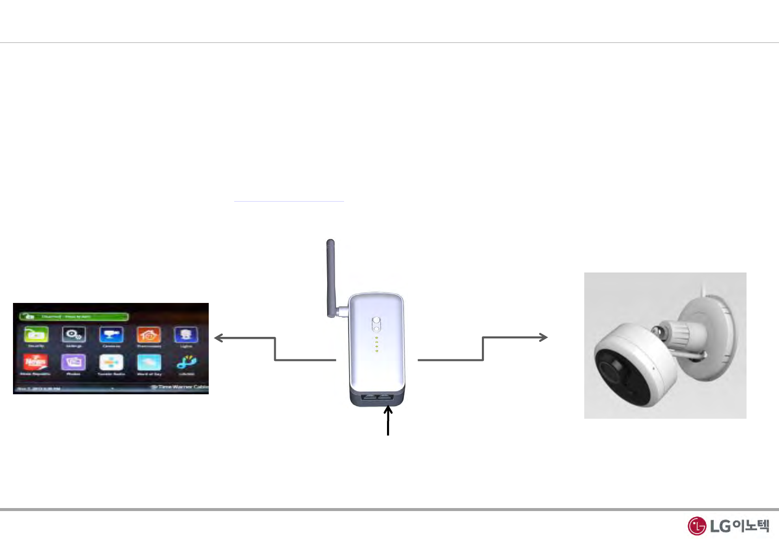
LAN Cable(CAMERA)
1. Log in connection Camera & Wi-Fi Bridge
1) Make sure that your camera is connected to the Wi-Fi Bridge CAMERA port with an Ethernet cable(wired)
2) Turn on the Wi-Fi Bridge and verify the following
- The power LED is On.
- The CAMERA LED is on for the LAN port that is connected to your Power device camera.
- The WLAN LED is blinking.
3) Launch internet browser and enter http://172.19.1.254 in the address field.
You are prompted to login;
Fig 4. Login connection
2. Installation Guide
3 / 12
CAMERA
WLAN

Copyrightⓒ. 2015. All Rights Reserved.
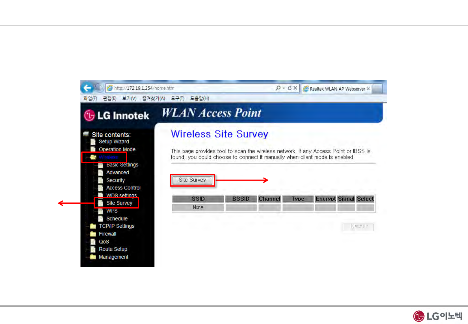
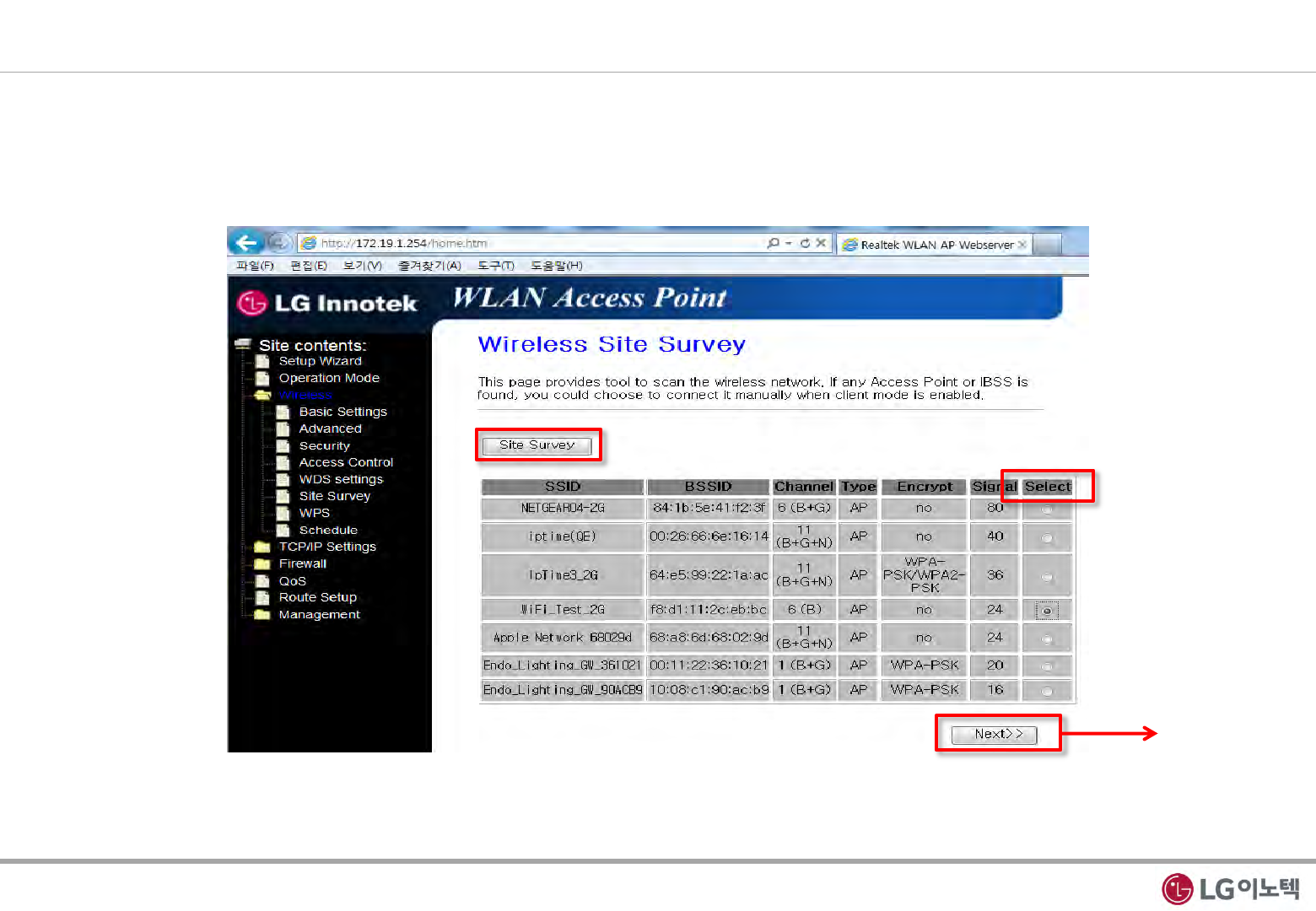
3. Wireless Site Survey
1) Please click “Wireless” in the webserver.
2) Please click “Site Survey” in the webserver( ①, ②), to fine AP list
Click ①
Click ②
Fig 6. Wireless Site Survey
5 / 12
Copyrightⓒ. 2015. All Rights Reserved.
Click
4. AP Connection
1) After “Site Survey”, you can show AP lists.
2) Please select wanted SSID(AP Name) and click “Next”
Fig 7. SSID Selection
6 / 12
Copyrightⓒ. 2015. All Rights Reserved.
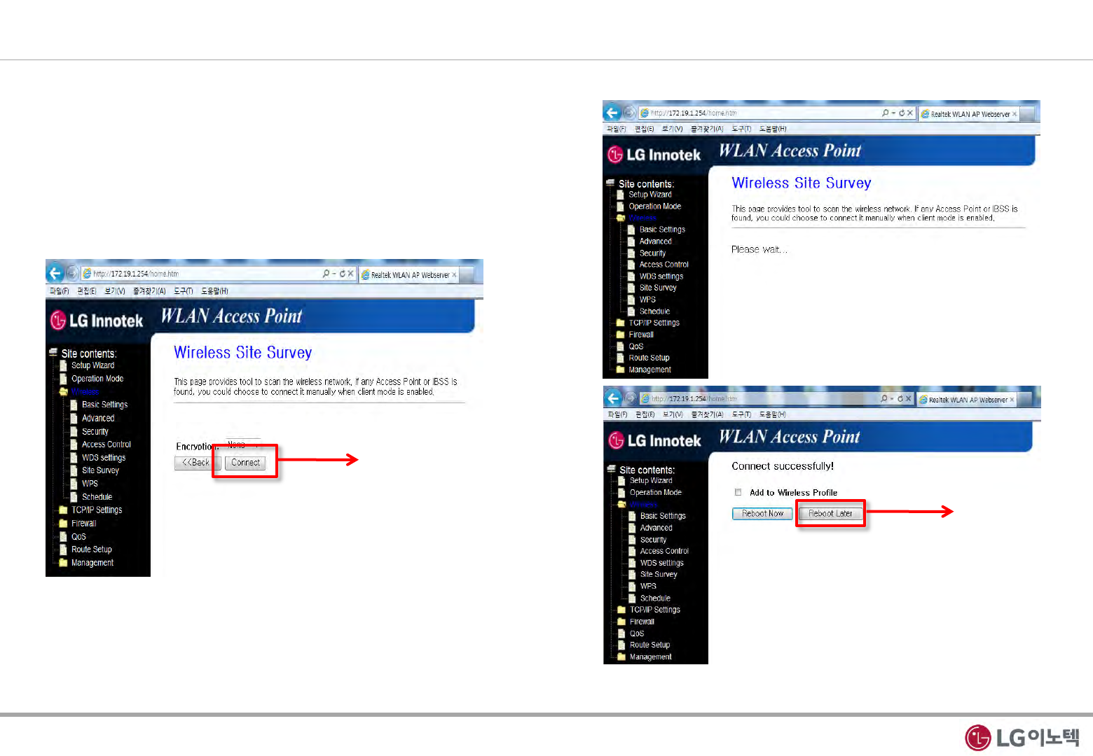
3) Please click “Connect”
4) After “Connect” click, You can show ”Please Wait” message
5) It will be connected. Please click ”Reboot Later”
6) Finally, Please close your web browser.
Click
Click
Fig 8. SSID Connection
7 / 12

Copyrightⓒ. 2015. All Rights Reserved.
3. Regulation Information
INFORMATION TO THE USER
This equipment has been tested and found to comply with the limits for a Class B digital device, pursuant to part 15 of the FCC
Rules. These limits are designed to provide reasonable protection against harmful interference in a residential installation. This
equipment generates, uses and can radiate radio frequency energy and, if not installed and used in accordance with the
instructions, may cause harmful interference to radio communications.
However, there is no guarantee that interference will not occur in a particular installation. If this equipment does cause harmful
interference to radio or television reception, which can be determined by turning the equipment off and on, the user is
encouraged to try to correct the interference by one or more of the following measures:
- Reorient or relocate the receiving antenna.
- Increase the separation between the equipment and receiver.
- Connect the equipment into an outlet on a circuit different from that to which the receiver is connected.
- Consult the dealer or an experienced radio/ TV technician for help.
This device complies with part 15 of the FCC Rules. Operation is subject to the following two conditions:
(1) This device may not cause harmful interference, and
(2) This device must accept any interference received, including interference that may cause undesired operation.
Caution: Any changes or modifications to the equipment not expressly approved by the party responsible for compliance could
void user’s authority to operate the equipment.
This appliance and its antenna must not be co-located or operation in conjunction with any other antenna or transmitter.
A minimum separation distance of 20 ㎝ must be maintained between the antenna and the person for this appliance to satisfy the
RF exposure requirements.
8 / 12

Copyrightⓒ. 2015. All Rights Reserved.
4. Regulation Information (French)
Le présent appareil est conforme aux CNR d'Industrie Canada applicables aux appareils radio exempts de licence.
L'exploitation est autorisée aux deux conditions suivantes:
(1) l'appareil ne doit pas produire de brouillage, et
(2) l'utilisateur de l'appareil doit accepter tout brouillage radioélectrique subi, même si le brouillage est susceptible d'en
compromettre le fonctionnement.
Cet équipement doit être installé et utilisé avec un minimum de 20 cm de distance entre la source de rayonnement et votre corps.
9 / 12
Copyrightⓒ. 2015. All Rights Reserved.
WPS
Reset
5. Appendix
1. WPS Function
- You can use WPS to connect AP without any password(WPA or WPA2).
① Push AP’ WPS button.
② Push PoE’ WPS Button(During 3 secs).
③ When try to connect AP, WLAN LED is pulsing RED.
④ After connect AP, WLAN LED is blinking Yellow Green.
If you didn’t push PoE’ WPS Button within 2min, It will be disconnected.
* Notice
- If you want to use WPS function, your AP must have WPS function.
2. Reset Function
- If you push RESET Button for 3secs, the PoE will restart.
3. Factory Default Setting
- Reset button can also be used to clear all data and restore the factory default settings.
① Press the Reset button(during 10 secs).
② Release the Reset button.
PoE will return to the factory configuration
settings shown in the following table.
Feature Default settings
User name (case-sensitive) printed on product label admin
Password (case-sensitive) printed on product label xxxxx
Static IP address 172.19.1.254
Ethernet MAC address See bottom label.
Subnet mask 255.255.255.0
DHCP client Disabled
Fig 9. WPS / Reset
Table 2. PoE default configuration settings
10 / 12
Copyrightⓒ. 2015. All Rights Reserved.
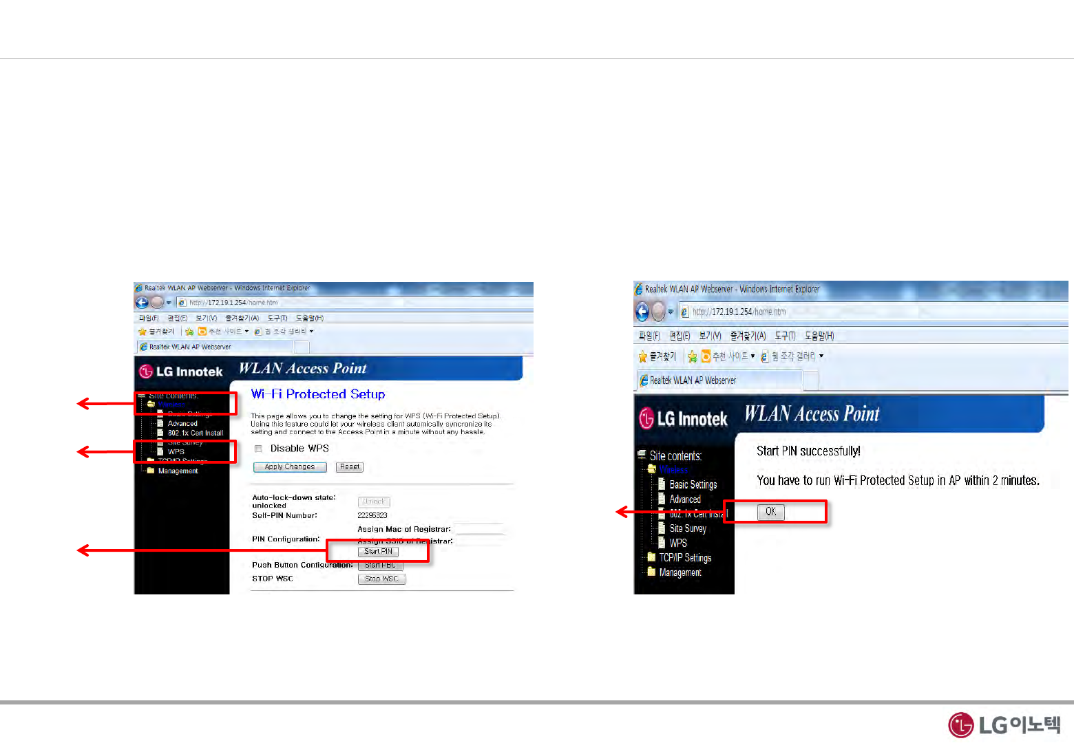
4. PIN mode WPS Function of webserver
① Please click “Wireless” in the webserver.
② Please click “WPS” in the webserver.
③ If you use PIN mode WPS, first input Self-PIN Number to AP. After that click Start PIN.
④ Click ok.
Click ①
Click ②
Click ③
Click ④
11 / 12
Copyrightⓒ. 2015. All Rights Reserved.
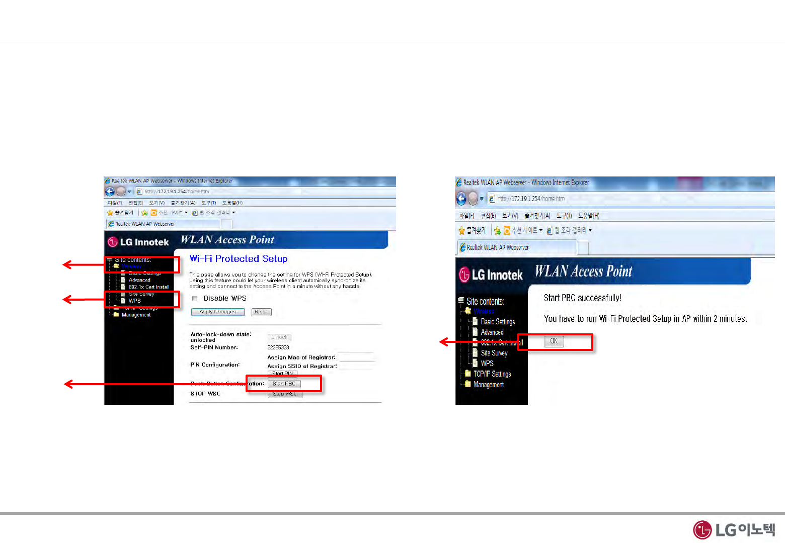
5. PIN mode WPS Function of webserver
① Please click “Wireless” in the webserver.
② Please click “WPS” in the webserver.
③ If you use PBC mode WPS in webserver, first push the WPS button of AP. After that click Start PBC.
④ Click ok.
Click ①
Click ②
Click ③
Click ④
12 / 12