LG Innotek TWFMK301D WI-FI Module User Manual
LG Innotek Co., Ltd. WI-FI Module
UserManual.wiki
>
LG Innotek
>
TWFMK301D User Manual
>
User manual
Contents
1.
User manual
2.
User Manual_20160127_v1 - YZP-TWFMK301D_USER_MANUAL
User manual
Navigation menu
Upload a User Manual
Namespaces
Wiki Guide
HTML
PDF
Info
Views
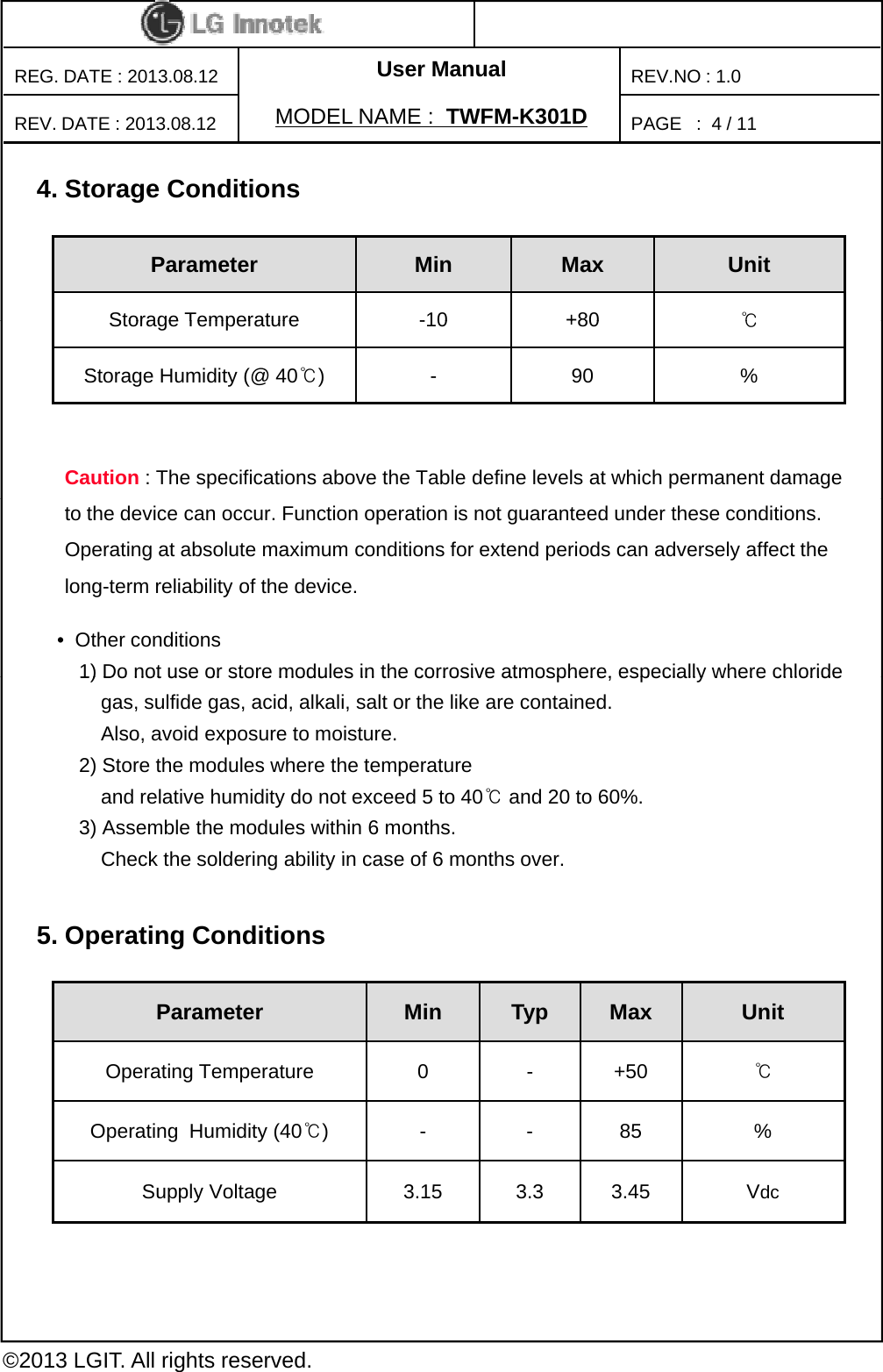
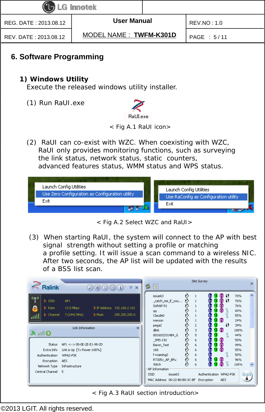
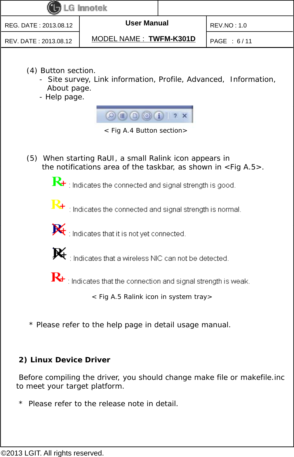
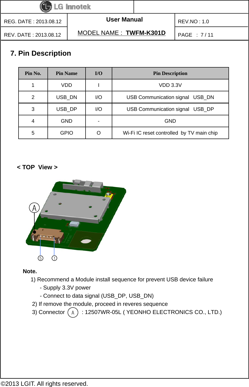
User Manual
Discussion / Help
Navigation