LG Innotek TWFMK301D WI-FI Module User Manual
LG Innotek Co., Ltd. WI-FI Module
Contents
- 1. User manual
- 2. User Manual_20160127_v1 - YZP-TWFMK301D_USER_MANUAL
User manual
User Manual
PRODUCT NAME : 1T1R Wi-Fi Module
MODEL NAME : TWFM-K301D
The information contained herein is the exclusive property of LG Innotek
and shall not be distributed, reproduced or disclosed in whole or no in part
without prior written permission of LG Innotek.
(00)-0073

User Manual
PAGE :
REG. DATE : 2013.08.12
MODEL NAME : TWFM-K301D
REV. DATE : 2013.08.12
REV.NO : 1.0
1/ 11
Table of Contents
No. Description Page
1
Features
2
1
Features
2
2 Module Photo 2
3 Block Diagram 3
4 Storage Conditions 4
4
OtiCditi
4
4
O
pera
ti
ng
C
on
diti
ons
4
5 Software Programming 5
6 Pin Description 7
7 Outline Drawing 8
8 Packing Information 9
©2013 LGIT. All rights reserved.
User Manual
PAGE :
REG. DATE : 2013.08.12
MODEL NAME : TWFM-K301D
REV. DATE : 2013.08.12
REV.NO : 1.0
2/ 11
1. Features
TWFM-K301D is the small size and low power module for IEEE 802.11b/g/n wireless
LAN. TWFM-K301D is based on Meatek MT7601U solution.
IEEE 802.11 b/g/n Single Band WLAN infrastructure
Size : 38mm x 26mm x 4mm
Auto-calibration
1T1R mode with 150Mbps PHY rate
Internal ANT : EPA(Embedded and Press Antenna)
USB 2.0
Supports drivers for for Windows 7, Vista, XP, 2000 and Linux
Security : WFA, WPA, WPA2, WPS2.0, WAPI
Application : DTV, DVR, HD DVD Player, Blue-ray Disk Player, STB
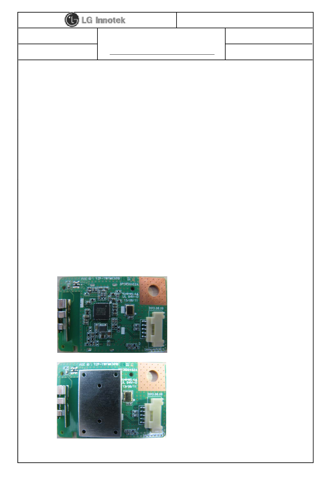
2. Module Photo
©2013 LGIT. All rights reserved.

User Manual
PAGE :
REG. DATE : 2013.08.12
MODEL NAME : TWFM-K301D
REV. DATE : 2013.08.12
REV.NO : 1.0
3/ 11
3. Block Diagram
Confidential
©2013 LGIT. All rights reserved.
User Manual
PAGE :
REG. DATE : 2013.08.12
MODEL NAME : TWFM-K301D
REV. DATE : 2013.08.12
REV.NO : 1.0
4/ 11
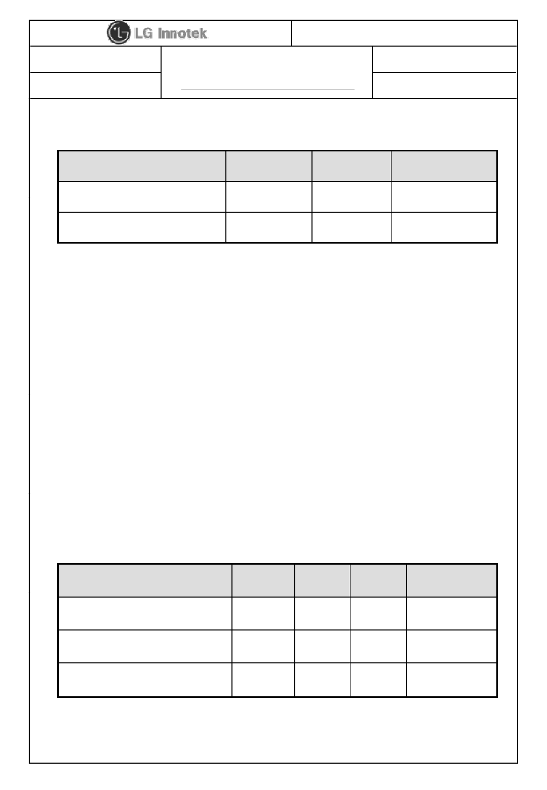
4. Storage Conditions
Parameter Min Max Unit
Storage Temperature
10
+80
℃
Storage
Temperature
-
10
+80
℃
Storage Humidity (@ 40℃)-90 %
Caution : The specifications above the Table define levels at which permanent damage
to the device can occur. Function operation is not guaranteed under these conditions.
Operating at absolute maximum conditions for extend periods can adversely affect the
long-term reliability of the device.
• Other conditions
1) Do not use or store modules in the corrosive atmosphere, especially where chloride
1)
Do
not
use
or
store
modules
in
the
corrosive
atmosphere,
especially
where
chloride
gas, sulfide gas, acid, alkali, salt or the like are contained.
Also, avoid exposure to moisture.
2) Store the modules where the temperature
and relative humidity do not exceed 5 to 40℃and 20 to 60%.
3) Assemble the modules within 6 months.
Ch k th ld i bilit i f 6 th
5. Operating Conditions
Ch
ec
k
th
e so
ld
er
i
ng a
bilit
y
i
n case o
f
6
mon
th
s over.
Parameter Min Typ Max Unit
Operating Temperature 0 - +50 ℃
Operating Humidity (40℃)--85 %
Supply Voltage 3.15 3.3 3.45 Vdc
©2013 LGIT. All rights reserved.
User Manual
PAGE :
REG. DATE : 2013.08.12
MODEL NAME : TWFM-K301D
REV. DATE : 2013.08.12
REV.NO : 1.0
5/ 11
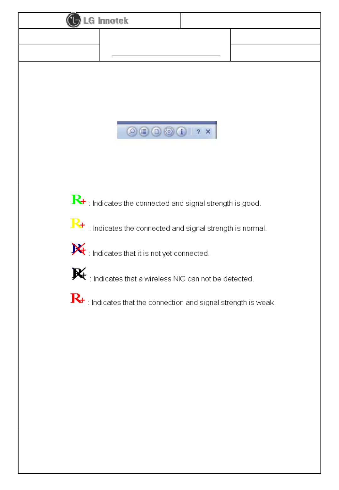
6. Software Programming
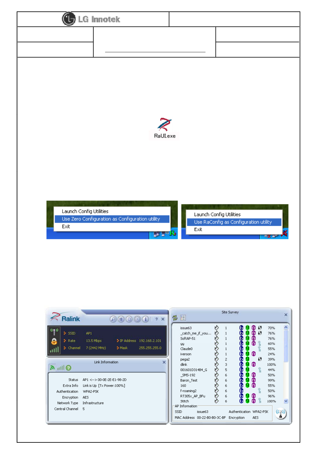
1) Windows Utility
Execute the released windows utility installer.
(1) Run RaUI.exe
(2) RaUI can co-exist with WZC. When coexisting with WZC,
RaUI only provides monitoring functions such as surveying
< Fig A.1 RaUI icon>
RaUI only provides monitoring functions
,
such as surveying
the link status, network status, static counters,
advanced features status, WMM status and WPS status.
(3) When starting RaUI, the system will connect to the AP with best
signal strength without setting a profile or matching
a profile setting. It will issue a scan command to a wireless NIC.
< Fig A.2 Select WZC and RaUI>
After two seconds, the AP list will be updated with the results
of a BSS list scan.
©2013 LGIT. All rights reserved.
< Fig A.3 RaUI section introduction>
User Manual
PAGE :
REG. DATE : 2013.08.12
MODEL NAME : TWFM-K301D
REV. DATE : 2013.08.12
REV.NO : 1.0
6/ 11
(4) Button section.
- Site survey, Link information, Profile, Advanced, Information,
About page.
- Help page.
(5) When starting RaUI, a small Ralink icon appears in
the notifications area of the taskbar as shown in <Fig A 5>
< Fig A.4 Button section>
the notifications area of the taskbar
,
as shown in <Fig A
.
5>
.
* Please refer to the help page in detail usage manual.
< Fig A.5 Ralink icon in system tray>
2) Linux Device Driver
Before compiling the driver, you should change make file or makefile.inc
to meet your target platform.
* Please refer to the release note in detail
©2013 LGIT. All rights reserved.
* Please refer to the release note in detail
.
User Manual
PAGE :
REG. DATE : 2013.08.12
MODEL NAME : TWFM-K301D
REV. DATE : 2013.08.12
REV.NO : 1.0
7/ 11
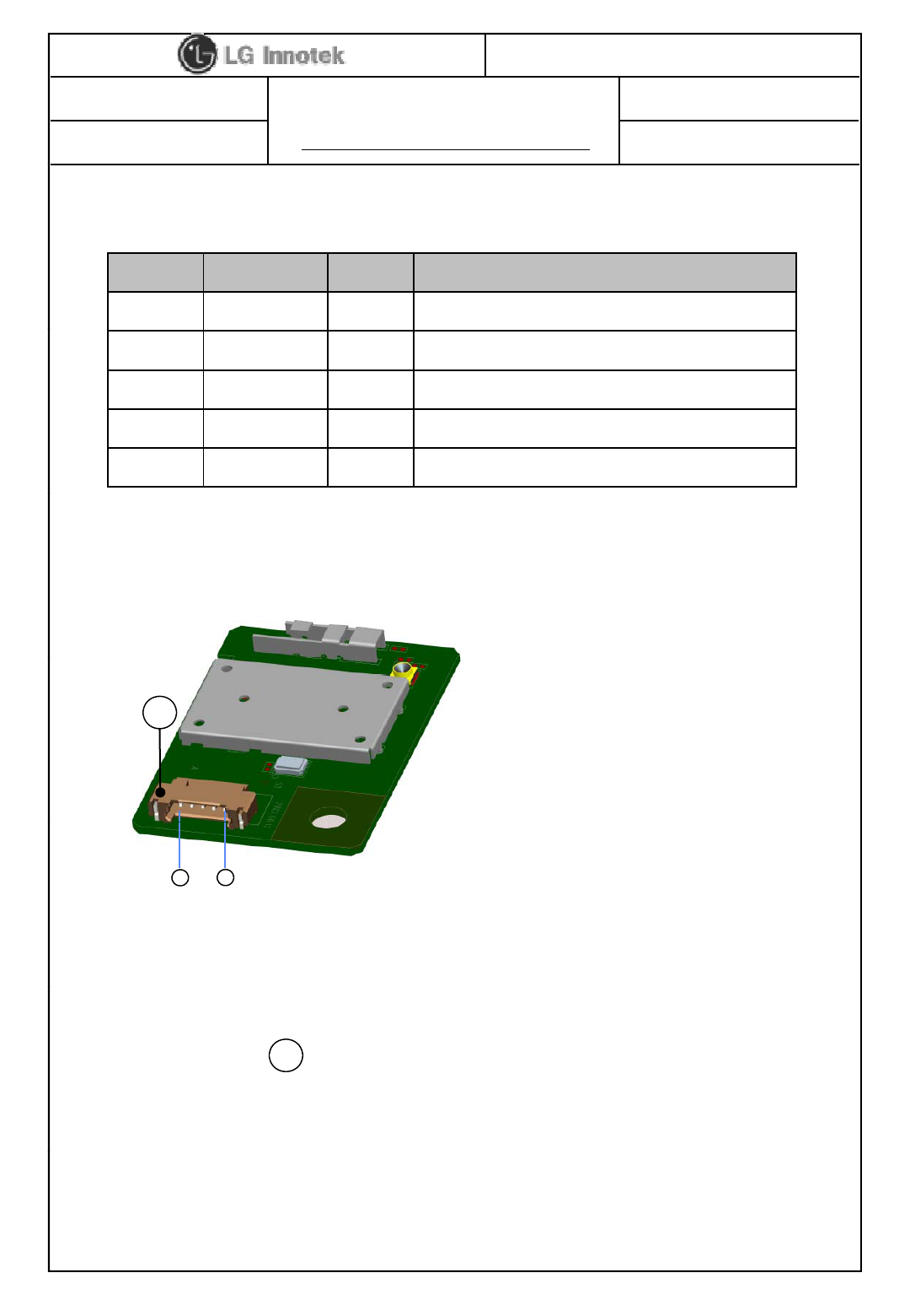
7. Pin Description
Pin No. Pin Name I/O Pin Description
1 VDD I VDD 3.3V
2 USB_DN I/O USB Communication signal USB_DN
3 USB_DP I/O USB Communication signal USB_DP
4 GND - GND
5 GPIO O Wi-Fi IC reset controlled by TV main chip
< TOP View >
A
Note.
1) Recommend a Module install sequence for prevent USB device failure
- Supply 3.3V power
1
5
- Connect to data signal (USB_DP, USB_DN)
2) If remove the module, proceed in reveres sequence
3) Connector : 12507WR-05L ( YEONHO ELECTRONICS CO., LTD.)
A
©2013 LGIT. All rights reserved.
User Manual
PAGE :
REG. DATE : 2013.08.12
MODEL NAME : TWFM-K301D
REV. DATE : 2013.08.12
REV.NO : 1.0
8/ 11
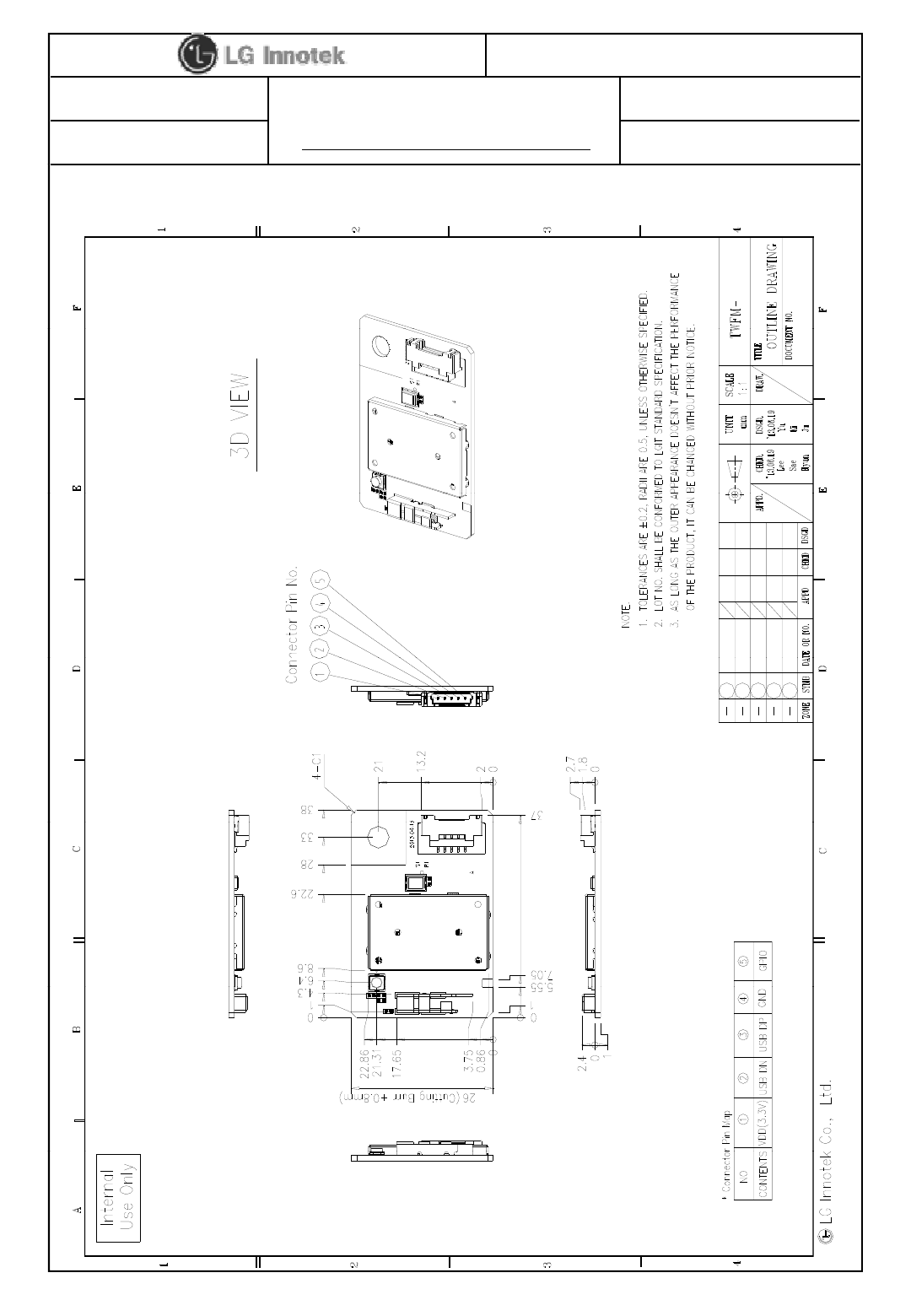
8. Outline Drawing
K301D
©2013 LGIT. All rights reserved.
User Manual
PAGE :
REG. DATE : 2013.08.12
MODEL NAME : TWFM-K301D
REV. DATE : 2013.08.12
REV.NO : 1.0
9/ 11
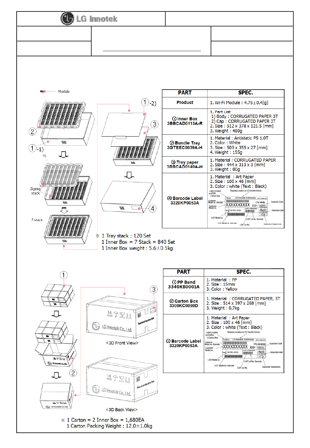
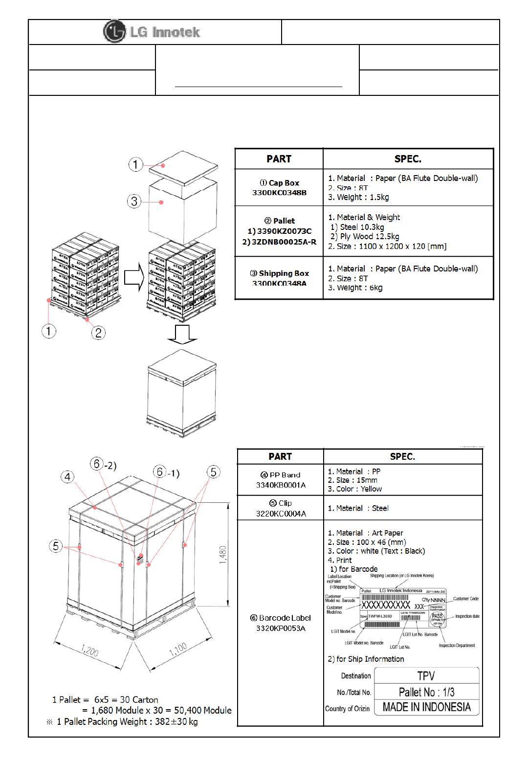
9. Packing Information
1) Inner Box Packing
2) Carton Box Packing
©2013 LGIT. All rights reserved.
User Manual
PAGE :
REG. DATE : 2013.08.12
MODEL NAME : TWFM-K301D
REV. DATE : 2013.08.12
REV.NO : 1.0
10 / 11
3) Pallet Packing
©2013 LGIT. All rights reserved.
User Manual
PAGE :
REG. DATE : 2013.08.12
MODEL NAME : TWFM-K301D
REV. DATE : 2013.08.12
REV.NO : 1.0
11 / 11
User Information
The satisfy FCC exterior labeling requirements, the following test must be placed on the exterior of the end product.
Contains Transmitter module FCC ID: YZP-TWFMK301D
This device complies with FCC radiation exposure limits set forth for an uncontrolled environment. This device
should be installed and operated with minimum distance 20cm between the radiating element of this device and the
user This device must not be co
-
located or operating in conjunction with any other antenna or transmitter
user
.
This
device
must
not
be
co
located
or
operating
in
conjunction
with
any
other
antenna
or
transmitter
.
This device is intended only for OEM integrators and following statements shall be included to host user manual
1) The antenna must be installed such that 20cm is maintained between the antenna and users.
2) This module may not be co-located with any other transmitters or antennas.
As long as 2 conditions above are met, further transmitter test will not be required. However, the OEM integrator is
still responsible for testing their end-product for any
additional compliance requirements with this module installed. In the event that these conditions cannot be met, then
the FCC authorizations are no lon
g
er considered valid and the FCC ID cannot be used on the final
p
roduct. In these
gp
circumstances, the OEM integrator will be responsible for re-evaluating the end product including this module and
obtaining separate FCC authorizations.
This equipment has been tested and found to comply with the limits for a Class B digital device, pursuant to Part 15
of the FCC Rules. These limits are designed to
provide reasonable protection against harmful interference in a residential installation. This equipment generates uses
and can radiate radio frequency energy and, if not installed and used in accordance with the instructions, may cause
hflitf tdi iti
h
arm
f
u
l
i
n
t
er
f
erence
t
o ra
di
o commun
i
ca
ti
ons.
However, there is no guarantee that interference will not occur in a particular installation. If this equipment does
cause harmful interference to radio or television reception, which can be determined by turning the equipment off
and on, the user is encouraged to try to correct the interference by one or more of the
following measures:
– Reorient or relocate the receiving antenna.
– Increase the separation between the equipment and receiver.
Connect the equipment into an outlet on a circuit different from that to which the receiver is connected
–
Connect
the
equipment
into
an
outlet
on
a
circuit
different
from
that
to
which
the
receiver
is
connected
.
– Consult the dealer or an experienced radio/TV technical for help.
– Reorient or relocate the receiving antenna.
– Increase the separation between the equipment and receiver.
– Connect the equipment into an outlet on a circuit different from that to which the receiver is connected.
– Consult the dealer or an experienced radio/TV technical for help.
This device complies with Part 15 of the FCC`s Rules. Operation is subject to the following two Conditions:
1. This device may not cause harmful interference, and
2. This device must accept any interference received, including interference that may cause undesirable operation.
This equipment may generate or use radio frequency energy. Changes or modifications to this equipment may cause
harmful interference unless the modifications are expressly approved in the instruction manual. The user could lose
the authority to operate this equipment if an unauthorized change or modification is made
©2013 LGIT. All rights reserved.