LG Innotek TWFMK301D WI-FI Module User Manual 20160127 v1 YZP TWFMK301D USER MANUAL
LG Innotek Co., Ltd. WI-FI Module 20160127 v1 YZP TWFMK301D USER MANUAL
Contents
- 1. User manual
- 2. User Manual_20160127_v1 - YZP-TWFMK301D_USER_MANUAL
User Manual_20160127_v1 - YZP-TWFMK301D_USER_MANUAL
USER MANUAL
PRODUCT NAME : Single Band 1T1R Wi-Fi Module
MODEL NAME : TWFM-K311D
This module is using VIZIO's MAC address provided by TPV
Designed Checked Approved
LG Innotek Co., Ltd.
T. G. JANG D. S. OH S. D. CHOI
Document No.
2015.12.04 2015.12.04 2015.12.04 PAGE 10
The information contained herein is the exclusive property of LG Innotek
and shall not be distributed, reproduced or disclosed in whole or no in part
without prior written permission of LG Innotek.

PAGE :
DOCUMENT No. :
REG. DATE :
MODEL NAME : TWFM-K311D
REV. No. :
©2015 LGIT. All rights reserved.
REV. DATE :
USER MANUAL
Table of Contents
No Description Page
1 Features 2
2 Ordering Information 2
3 Label Marking 2
4 Storage Test Conditions 3
5 Operating Test Conditions 4
6 Standard Test Conditions 4
7 Mechanical Characteristics 5
8 Software Programming 6
9 Pin Description 8
10
11
Outline Drawing
Warning
9
10
1 / 10
PAGE :
DOCUMENT No. :
REG. DATE :
MODEL NAME : TWFM-K311D
REV. No. :
©2015 LGIT. All rights reserved.
REV. DATE :
USER MANUAL
2. Ordering Information
Model Description
TWFM-K311D Wi-Fi Module, Single Band , 1T1R
1. Features
TWFM-K311D is the module for IEEE 802.11b/g/n wireless LAN.
TWFM-K311D is based on MTK MT7601U solution.
IEEE 802.11 b/g/n single band WLAN infrastructure
Size : 38.0mm x 26.0mm x 3.8mm
External Antenna
Auto-calibration
1T1R mode with 150Mbps PHY rate
USB 2.0 interface
Supports drivers for Windows 7, Vista, XP, 2000 and Linux
Security : WFA, WPA, WPA2, WPS2.0, WAPI
Application : DTV, DVR, HD DVD Player, Blue-ray Disk Player, STB
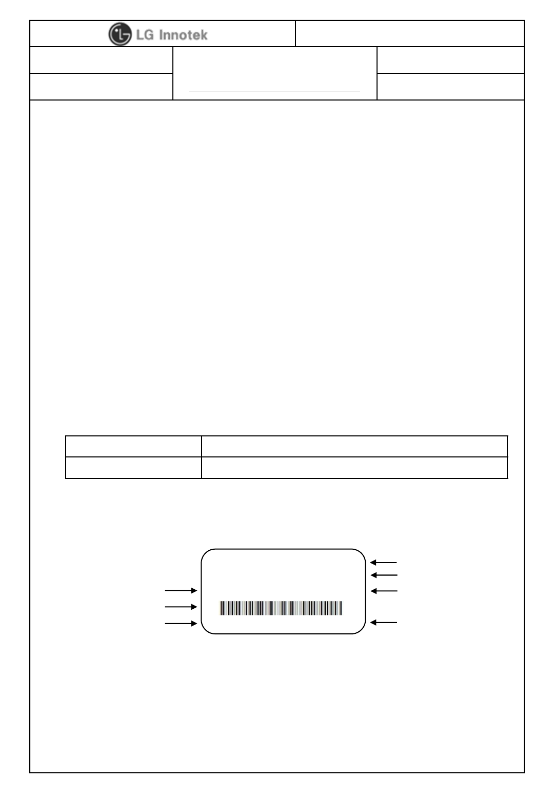
3. Label Marking(IC)
①Customer P/N ④Product Lot No. : 1512A0401
②MAC Address BAR Code - 15 : Year - 04 : Date
③LGIT Model No. - 12 : Month - 01 : Manufactured
- Revision No. : A Process
⑤IC ID(7414C-TWFMK301D) ⑥IFETEL ID(RCPLGTW14-1843)
⑦MAC Address will be applied which TPV provided
①
②
③M/N:TWFM-K311D 001EB2B00339
④
IC : 7414C-TWFMK301D ⑤
IFETEL ID: RCPLGTW14-1843 ⑥
317GAAWF619LGI0VIZ 1512A0401
⑦
2 / 10

PAGE :
DOCUMENT No. :
REG. DATE :
MODEL NAME : TWFM-K311D
REV. No. :
©2015 LGIT. All rights reserved.
REV. DATE :
USER MANUAL
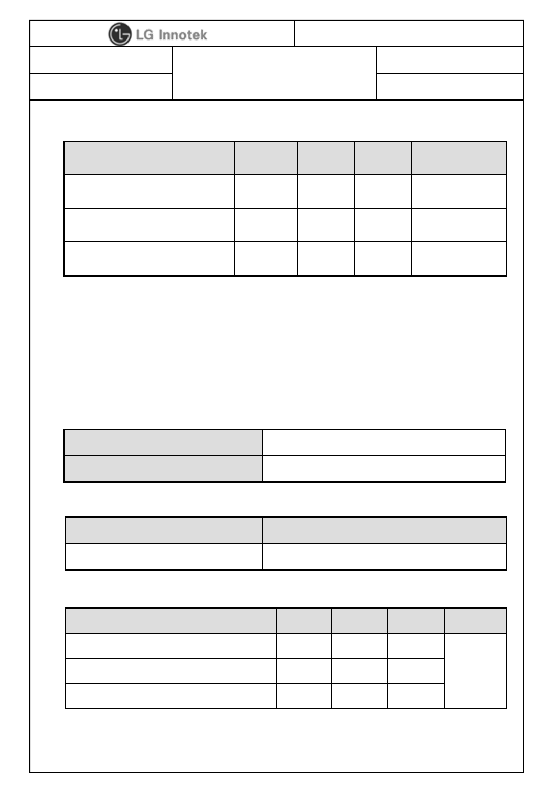
Parameter Min Max Unit
Storage temperature -20 +80 ℃
Storage humidity (@ 40℃)-90 %
Caution : The specifications above table define levels at which permanent damage to
the device can occur. Function operation is not guaranteed under these conditions.
Operating at absolute maximum conditions for extend periods can adversely affect the
long-term reliability of the device.
* Other conditions
1) Do not use or store modules in the corrosive atmosphere, especially where chloride
gas, sulfide gas, acid, alkali, salt or the like are contained.
Also, avoid exposure to moisture.
2) Store the modules where the temperature
and relative humidity do not exceed 5 to 40℃and 20 to 60%.
3) Assemble the modules within 6 months.
Check the soldering ability in case of 6 months over.
4. Storage Test Conditions
3 / 10
PAGE :
DOCUMENT No. :
REG. DATE :
MODEL NAME : TWFM-K311D
REV. No. :
©2015 LGIT. All rights reserved.
REV. DATE :
USER MANUAL
Parameter Min Typ Max Unit
Operating temperature 0 - +50 ℃
Operating humidity (40℃)--85 %
Supply voltage 4.75 5.0 5.25 Vdc
The Test for electrical specification shall be performed under the following condition
Otherwise this following conditions, not guaranteed this performance.
5. Operating Test Conditions
Temperature 25 ±5℃
Humidity 65 ±5%
Input power Supply Voltage
+5V +5.0V ±0.25V(5%)
6. Standard Test Conditions
6-1. Ambient condition
6-2. Power supply voltages
6-3. Current consumption
Current consumption Min. Typ. Max. Unit
TX Mode ( MCS7 HT40) - 210 320
mARX Mode ( MCS7 HT40) - 151 220
Sleep mode - 1.1 20
4 / 10
PAGE :
DOCUMENT No. :
REG. DATE :
MODEL NAME : TWFM-K311D
REV. No. :
©2015 LGIT. All rights reserved.
REV. DATE :
USER MANUAL
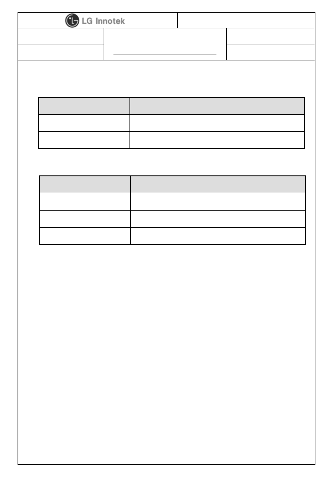
7. Mechanical Characteristics
8-1. Outline view
8-2. Appearance structure
Item Test conditions
Assembly No defects of wiring, soldering and assembling
Appearance No dirt, rust, corrosion or foreign material
Item Test conditions
Dimension As assembly drawing
Mounting As assembly drawing
Weight Approximately 5.88 ±0.6g
5 / 10
PAGE :
DOCUMENT No. :
REG. DATE :
MODEL NAME : TWFM-K311D
REV. No. :
©2015 LGIT. All rights reserved.
REV. DATE :
USER MANUAL
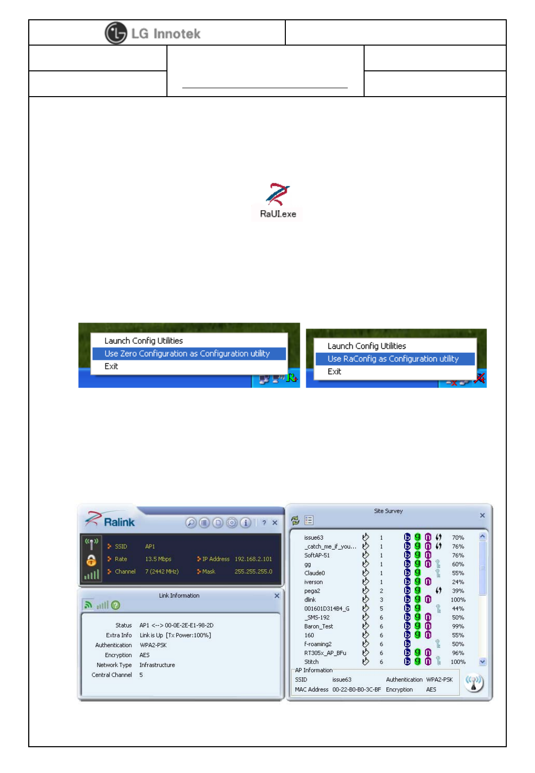
1) Windows Utility
Execute the released windows utility installer.
(1) Run RaUI.exe
(2) RaUI can co-exist with WZC. When coexisting with WZC,
RaUI only provides monitoring functions, such as surveying
the link status, network status, static counters,
advanced features status, WMM status and WPS status.
(3) When starting RaUI, the system will connect to the AP with best
signal strength without setting a profile or matching
a profile setting. It will issue a scan command to a wireless NIC.
After two seconds, the AP list will be updated with the results
of a BSS list scan.
< Fig A.1 RaUI icon>
< Fig A.2 Select WZC and RaUI>
< Fig A.3 RaUI section introduction>
8. Software Programming
6 / 10
PAGE :
DOCUMENT No. :
REG. DATE :
MODEL NAME : TWFM-K311D
REV. No. :
©2015 LGIT. All rights reserved.
REV. DATE :
USER MANUAL
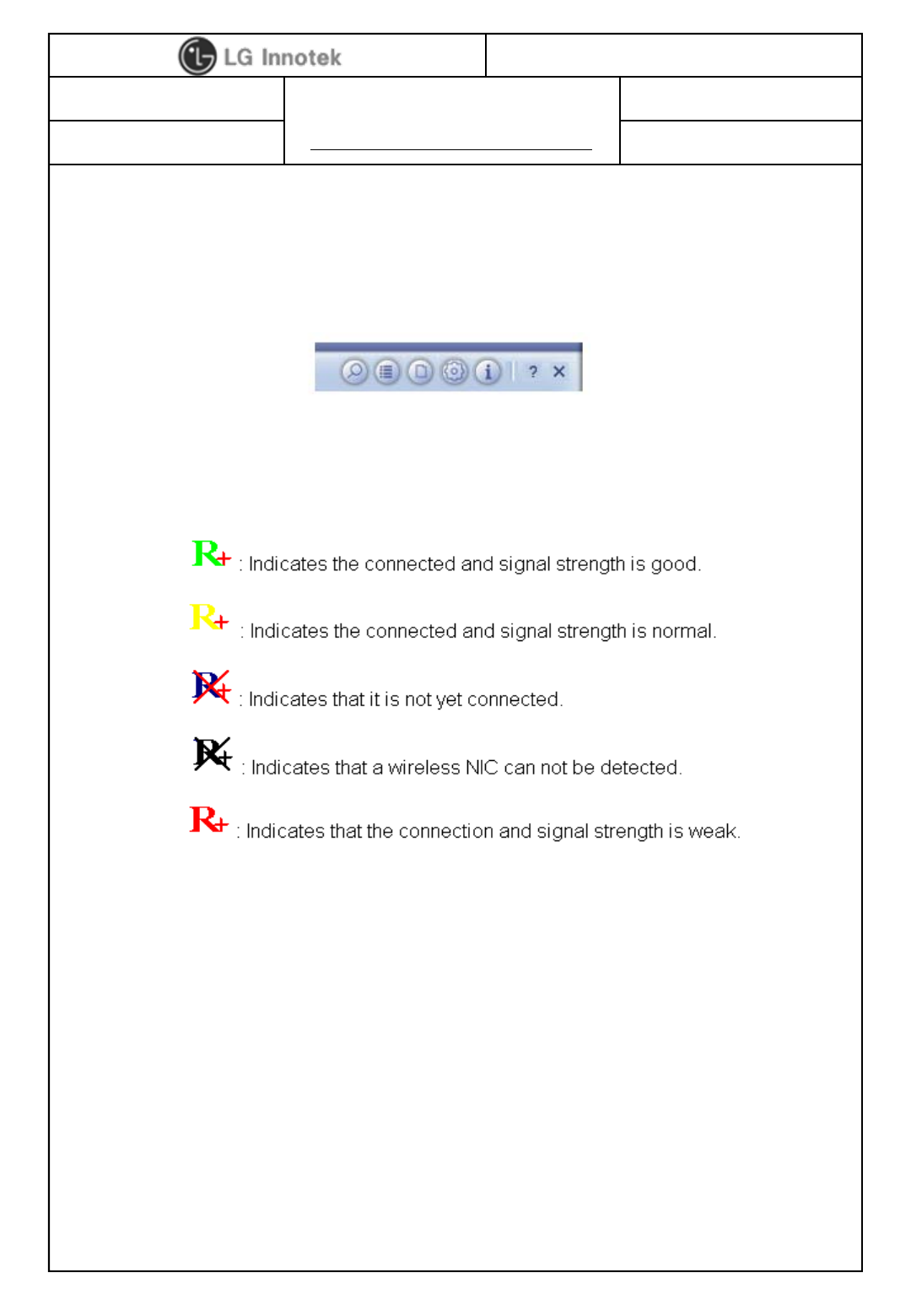
(4) Button section.
- Site survey, Link information, Profile, Advanced, Information,
About page.
- Help page.
(5) When starting RaUI, a small Ralink icon appears in
the notifications area of the taskbar, as shown in <Fig A.5>.
* Please refer to the help page in detail usage manual.
2) Linux Device Driver
Before compiling the driver, you should change make file or
makefile.inc to meet your target platform.
* Please refer to the release note in detail.
< Fig A.4 Button section>
< Fig A.5 Ralink icon in system tray>
7 / 10
PAGE :
DOCUMENT No. :
REG. DATE :
MODEL NAME : TWFM-K311D
REV. No. :
©2015 LGIT. All rights reserved.
REV. DATE :
USER MANUAL
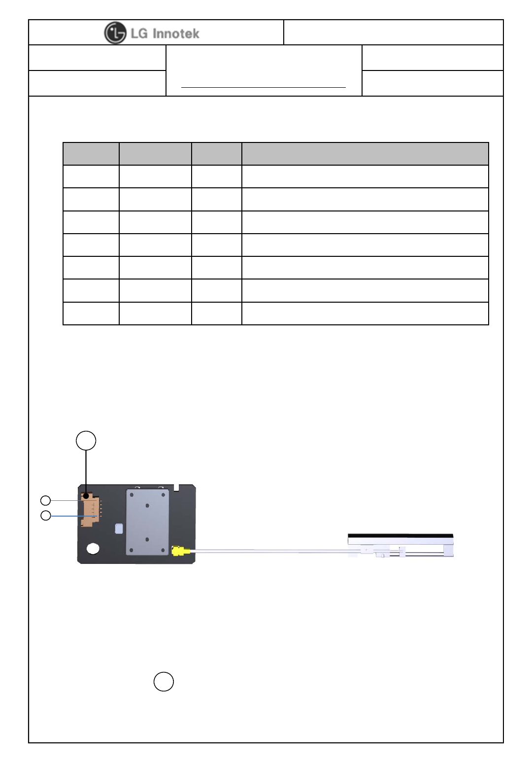
9. Pin Description
< TOP View >
Pin No. Pin Name I/O Pin Description
1 VDD I VDD +5V
2 VDD I VDD +5V
3 GND - Ground
4 USB_DN I/O USB Communication signal USB_DN
5 USB_DP I/O USB Communication signal USB_DP
6 GND - Ground
7 RESET I Wi-Fi IC reset controlled by TV main chip
A
1
7
Note.
1) Recommend module install sequence for preventing USB device failure
-1
st step : Supply +5V power
-2
nd step : Connect to data signal (USB_DP, USB_DN)
2) Connector : A
8 / 10
PAGE :
DOCUMENT No. :
REG. DATE :
MODEL NAME : TWFM-K311D
REV. No. :
©2015 LGIT. All rights reserved.
REV. DATE :
USER MANUAL
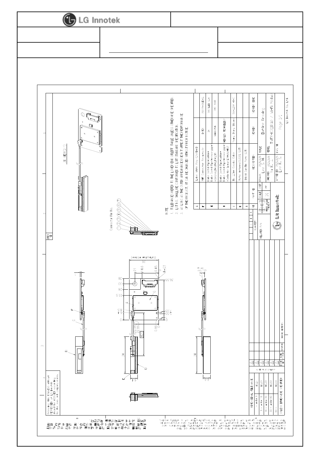
10. Outline Drawing
9 / 10

PAGE :
DOCUMENT No. :
REG. DATE :
MODEL NAME : TWFM-K311D
REV. No. :
©2015 LGIT. All rights reserved.
REV. DATE :
USER MANUAL
11. Warning
10 / 10
FCC
Any changes or modifications not expressly approved by the party responsible for compliance could void the user’s
authority to operate this device.
This device complies with Part 15 of the FCC`s Rules. Operation is subject to the following two Conditions:
1. This device may not cause harmful interference, and
2. This device must accept any interference received, including interference that may cause undesirable operation.
This device generates, uses and can radiate radio frequency energy and, if not installed and used in accordance
with the instructions, may cause harmful interference to radio communications. However, there is no guarantee
that interference will not occur in a particular installation. If this equipment does cause harmful interference to radio
or television reception, which can be determined by turning the equipment off and on, the user is encouraged to try
to correct the interference by one or more of the following measures:
– Reorient or relocate the receiving antenna.
– Increase the separation between the equipment and receiver.
– Connect the equipment into an outlet on a circuit different from that to which the receiver is connected.
– Consult the dealer or an experienced radio/TV technical for help.
This device complies with FCC/IC radiation exposure limits set forth for an uncontrolled environment.
This device should be installed and operated with minimum distance 20cm between the radiating element of this
device and the user. This device must not be co-located or operating in conjunction with any other antenna or
transmitter.
The satisfy FCC exterior labeling requirements, the following test must be placed on the exterior of the end product.
Contains Transmitter module FCC ID: YZP-TWFMK301D
IC
This device complies with Industry Canada license-exempt RSS standard(s). Operation is subject to the following
two conditions: (1) this device may not cause interference, and (2) this device must accept any interference,
including interference that may cause undesired operation of the device.
Le présent appareil est conforme aux CNR d'Industrie Canada applicables aux appareils radio exempts de licence.
L'exploitation est autorisée aux deux conditions suivantes : (1) l'appareil ne doit pas produire de brouillage, et (2)
l'utilisateur de l'appareil doit accepter tout brouillage radioélectrique subi, même si le brouillage est susceptible d'en
compromettre le fonctionnement.
The host device must be labeled to display the Industry Canada certification number of the module.
Contains transmitter module IC: 7414C-TWFMK301D
Le dispositif d'accueil doivent être étiquetés pour afficher le numéro de certification d'Industrie Canada du module.
Contient module émetteur IC : 7414C-TWFMK301D
This radio transmitter has been approved by Industry Canada to operate with the antenna types listed below with the
maximum permissible gain indicated. Antenna types not included in this list, having a gain greater than the maximum
gain indicated for that type, are strictly prohibited for use with this device.
Cet émetteur radio a été approuvé par Industrie Canada pour fonctionner avec les types d'antenne énumérés ci-dessous
avec le gain maximal admissible indiqué. Les types d'antennes ne figurant pas dans cette liste, ayant un gain supérieur
au gain maximum indiqué pour ce type, sont strictement interdits pour une utilisation avec cet appareil.