LG Innotek TWFML303D Wi-Fi Module User Manual
LG Innotek Co., Ltd. Wi-Fi Module
UserManual.wiki
>
LG Innotek
>
TWFML303D User Manual
user manual
Navigation menu
Upload a User Manual
Namespaces
Wiki Guide
HTML
PDF
Info
Views
User Manual
Discussion / Help
Navigation
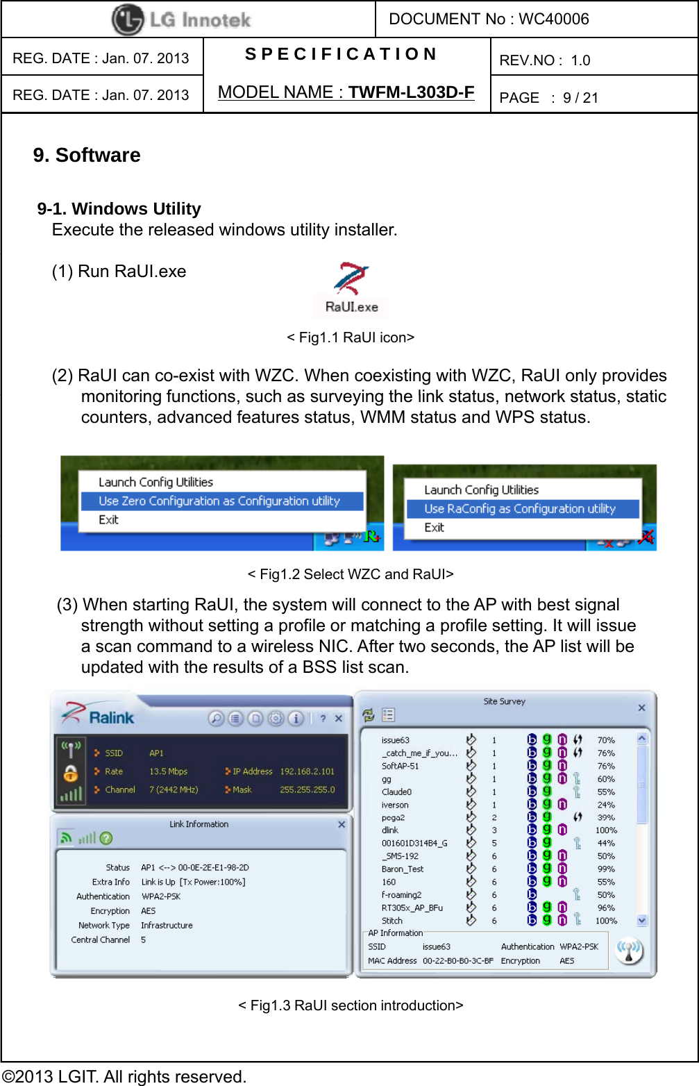
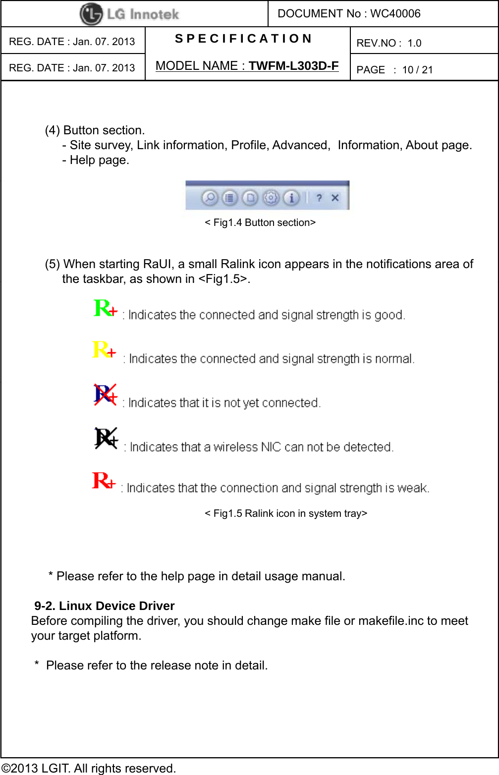
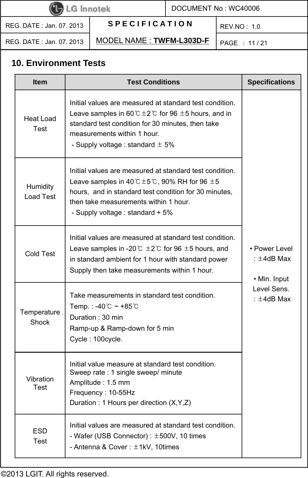
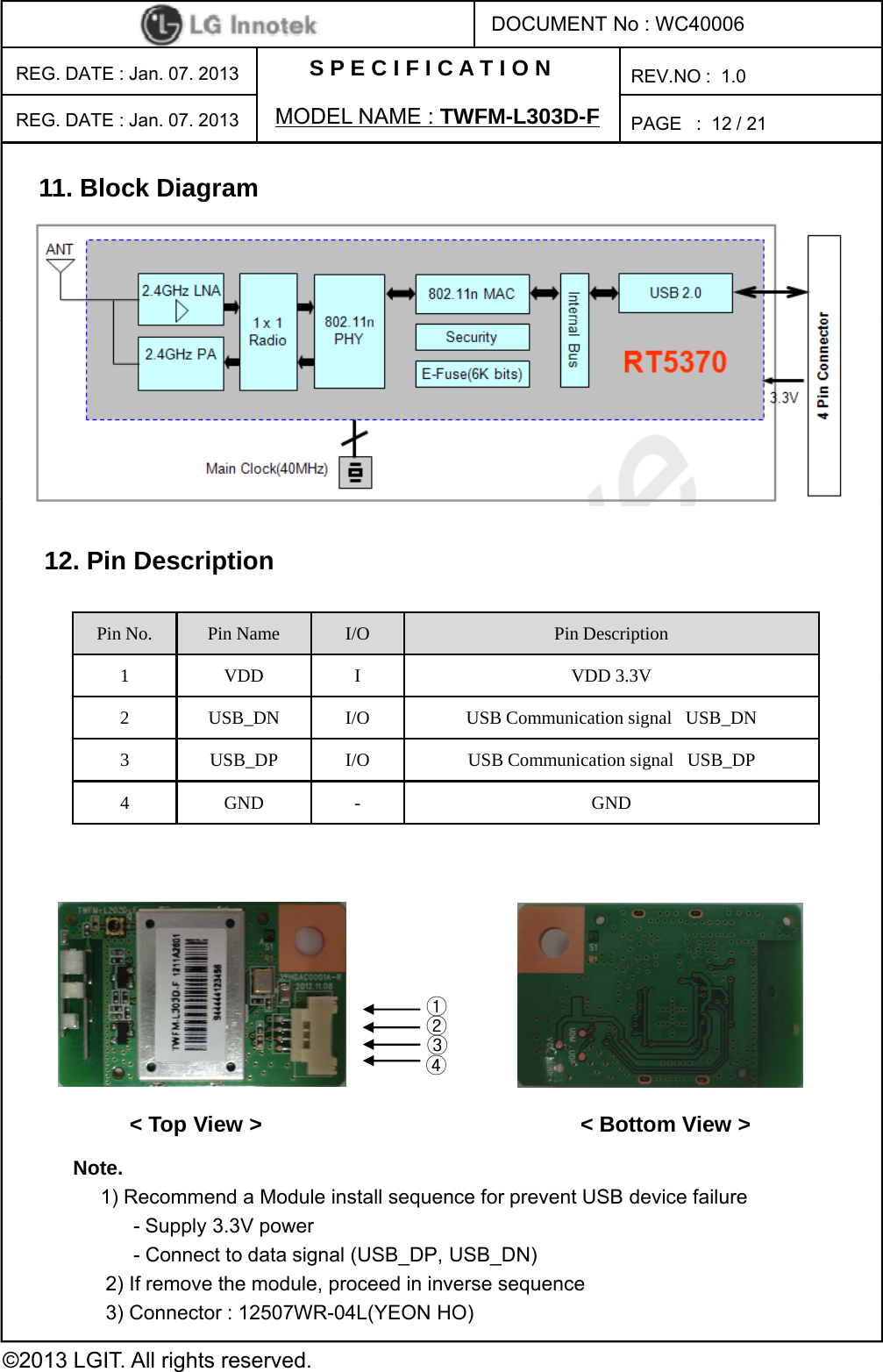
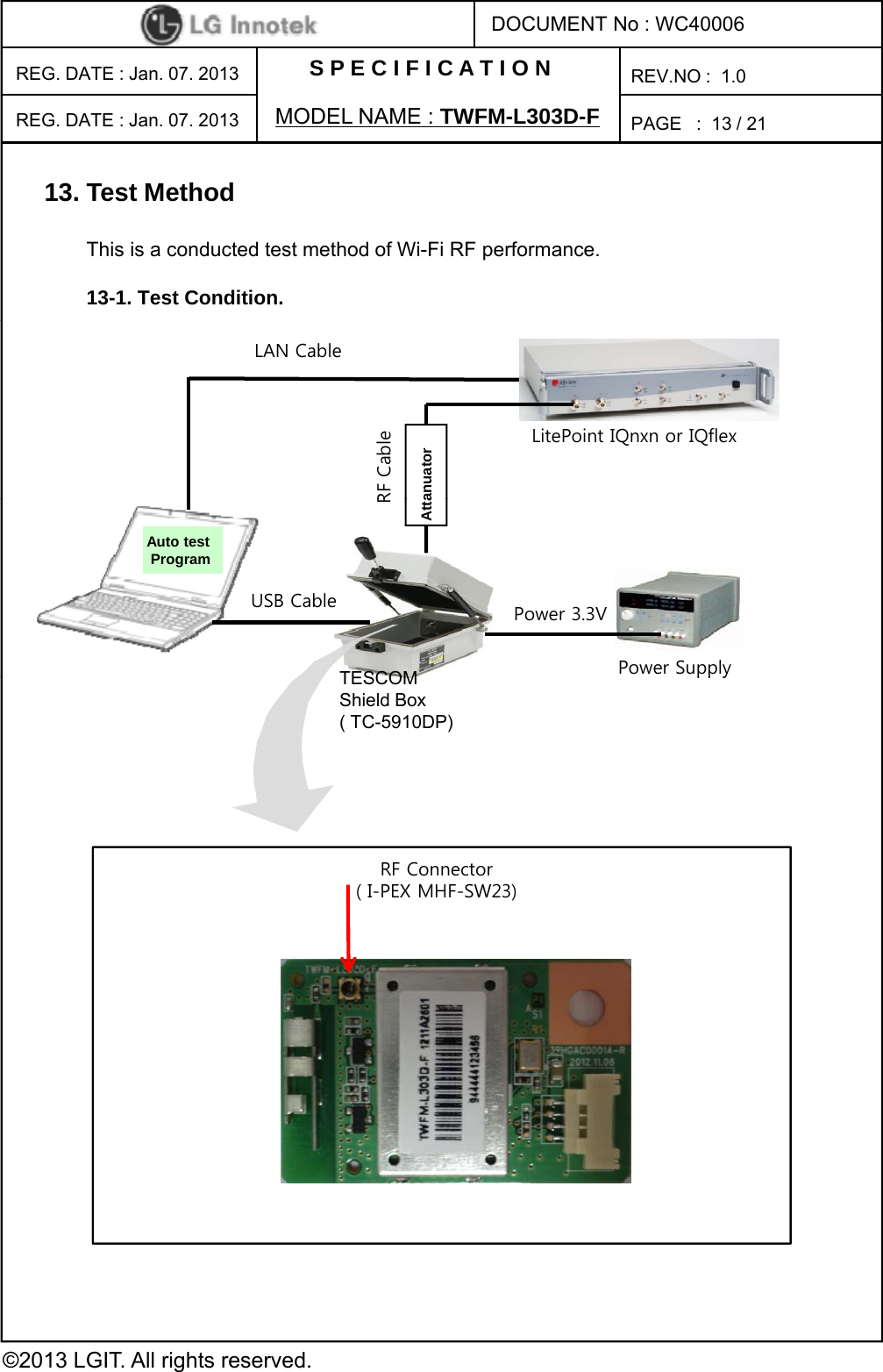
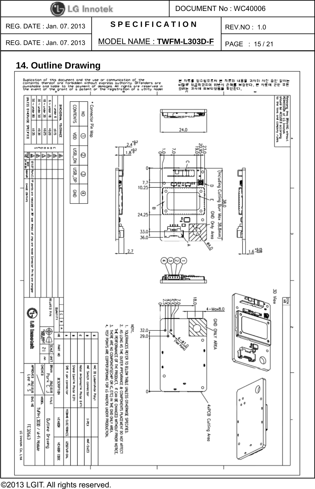
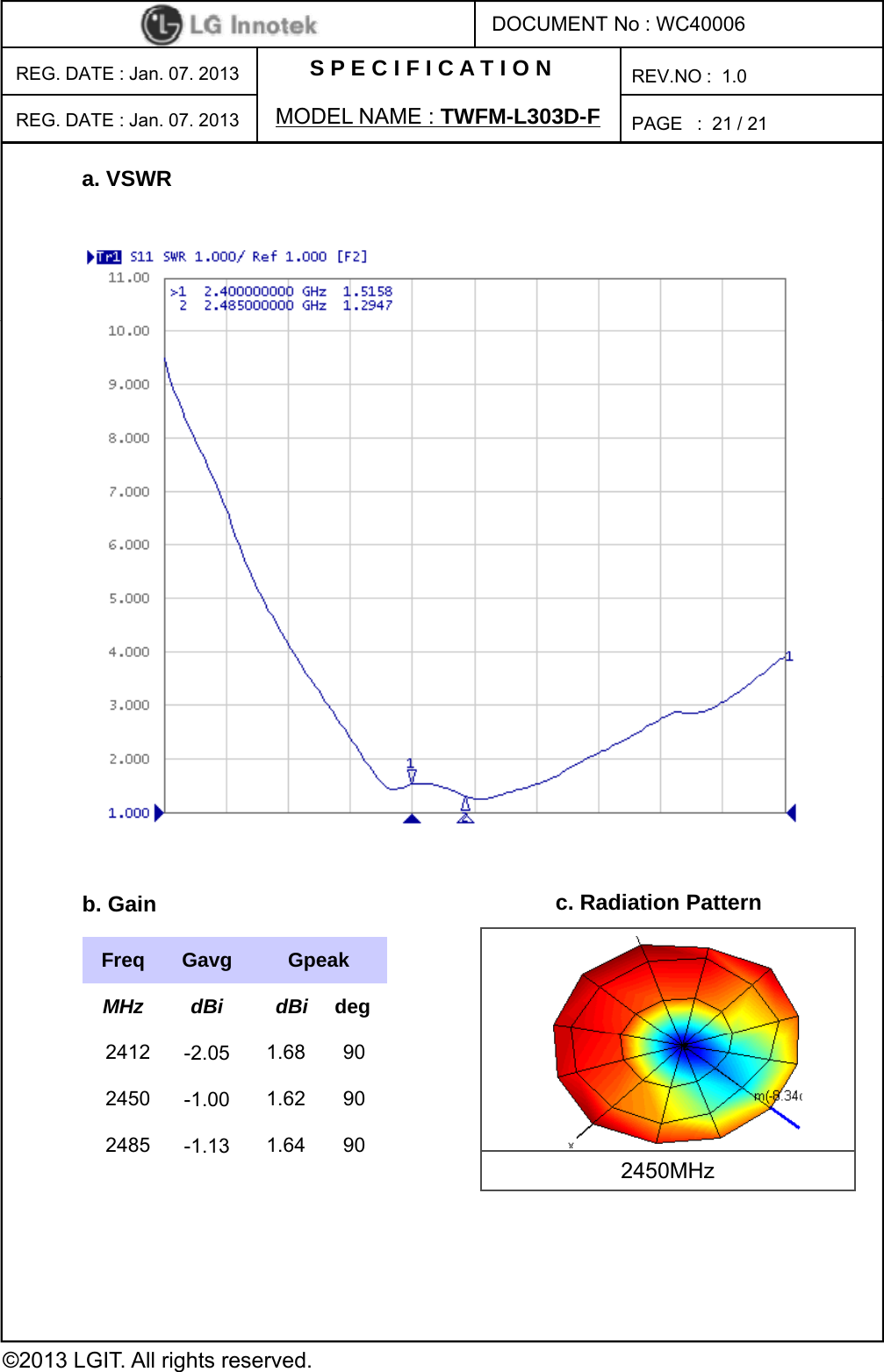
![S P E C I F I C A T I O NPAGE :DOCUMENT No : WC40006REG. DATE : Jan. 07. 2013 MODEL NAME : TWFM-L303D-FREV.NO : 1.08/ 21REG. DATE : Jan. 07. 2013 8. Mechanical Characteristics8-1. Outline viewItem Test Conditions 8-2. Appearance structureAssembly No defects of wiring, soldering and assemblingAppearance No dirt, rust, corrosion or foreign material Item Test Conditions Dimension As outline drawingMounting As outline drawingWeightApproximately 4 75±04[g]WeightApproximately 4.75±0.4 [g]©2013 LGIT. All rights reserved.](https://usermanual.wiki/LG-Innotek/TWFML303D/User-Guide-1881423-Page-9.png)