LG Innotek TWFML303D Wi-Fi Module User Manual
LG Innotek Co., Ltd. Wi-Fi Module
user manual

SPECIFICATIONS
PRODUCT NAME : Single Band 1T1R Wi-Fi Module
MODEL NAME : TWFM-L303D-F
The information contained herein is the exclusive property of LG Innotek
and shall not be distributed, reproduced or disclosed in whole or no in part
without prior written permission of LG Innotek.
Designed Checked Approved
LG Innotek Co., Ltd.
K.H.Lee D.S.Oh S.D.Choi
DOCUMENT No. WC40006
Jan. 07.2013 Jan. 07.2013 Jan. 07.2013 PAGE 21
(00)-0073
S P E C I F I C A T I O N
PAGE :
DOCUMENT No : WC40006
REG. DATE : Jan. 07. 2013
MODEL NAME : TWFM-L303D-F
REV.NO : 1.0
1/ 21
REG. DATE : Jan. 07. 2013
Table of Contents
No Description Page
1
F
1
F
eatures 2
2 Ordering Information 2
3 Label Marking 2
4 Storage Test Conditions 3
5 Operating Test Conditions 4
6 Standard Test Conditions 4
7 Electrical Characteristics 5
8 Mechanical Characteristics 8
9 Software 9
10 Environment Tests 11
11 Block Diagram 12
12 Pin Description 12
13 Test Method 13
14 Outline Drawing 15
15 Packing Information 16
16 Changing History of Revision 19
# Appendix 20
1. Antenna Characteristics
©2013 LGIT. All rights reserved.
S P E C I F I C A T I O N
PAGE :
DOCUMENT No : WC40006
REG. DATE : Jan. 07. 2013
MODEL NAME : TWFM-L303D-F
REV.NO : 1.0
2/ 21
REG. DATE : Jan. 07. 2013
1. Features
TWFM-L303D-F is the small size and low power module for IEEE 802.11b/g/n WLAN.
TWFM-L303D –F is based Ralink RT5370 solution.
IEEE 802.11 b/g/n Single Band WLAN infrastructure
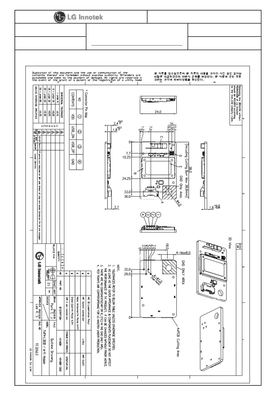
Size : 38.0mm x 24.0mm x 4.4mm
Metal Press Antenna
2.4GHz internal PA
1T1R Mode with 150Mbps PHY Rate for Both Transmit and Receiving
USB 2.0
Supports drivers for Windows Vista, XP, 2000, Linux
Security : WEP64/128, WPA, WPA2, TKIP, AES, WAPI
Application : DTV, DVR, HD DVD Player, Blue-ray Disk Player, STB
2. Ordering Information
Model Description
TWFM-L303D-F Wi-Fi Module, Single Band 1T1R
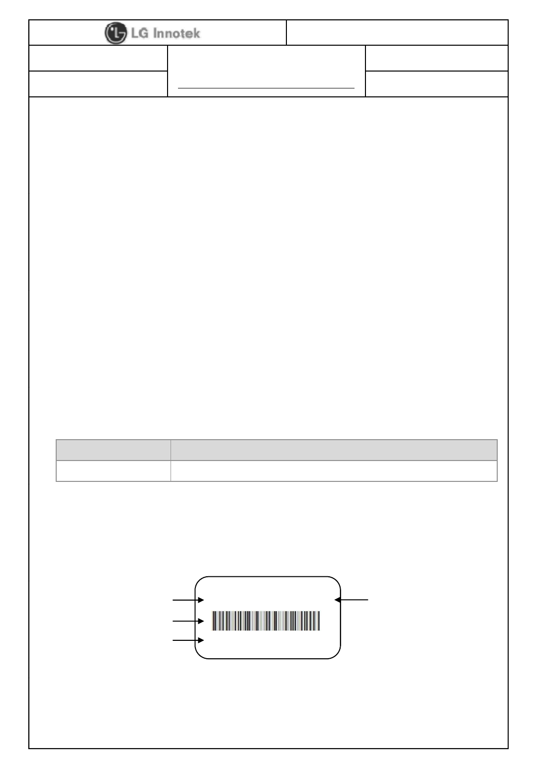
3. Label marking
①
②
③
TWFM-L303D 1301A0401
00199DFA4542
④
①
Model No
④
Product Lot No : 1301A0401
©2013 LGIT. All rights reserved.
①
Model
No
④
Product
Lot
No
.
:
1301A0401
②MAC Address BAR Code - 13 : Year - 04 : Date
③MAC Address No. - 01: Month - 01 : Manufactured
- Revision No. : A Process
S P E C I F I C A T I O N
PAGE :
DOCUMENT No : WC40006
REG. DATE : Jan. 07. 2013
MODEL NAME : TWFM-L303D-F
REV.NO : 1.0
3/ 21
REG. DATE : Jan. 07. 2013
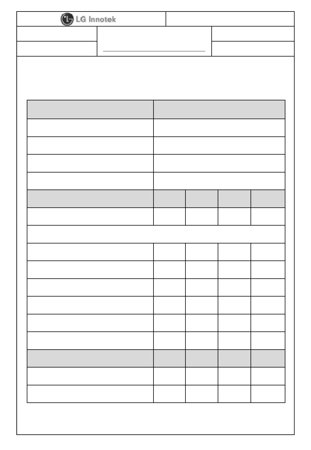
4. Storage Test Conditions
Parameter Min Max Unit
Storage Temperature -10 +80 ℃
Storage Humidity(40℃)-90 %
Caution : The specifications in Table 1 define levels at which permanent damage to the
device can occur. Function operation is not guaranteed under these conditions.
Operating at absolute maximum conditions for extend periods can adversely affect the
long-term reliability of the device.
Other conditions
1) Do not use or store modules in the corrosive atmosphere, especially where chloride
gas, sulfide gas, acid, alkali, salt or the like are contained.
Also, avoid exposure to moisture.
2) Store the modules is recommended where the temperature
and relative humidity 5 to 40℃and 20 to 60%.
3) Assemble the modules within 6 months.
Check the soldering ability in case of 6 months over.
©2013 LGIT. All rights reserved.
S P E C I F I C A T I O N
PAGE :
DOCUMENT No : WC40006
REG. DATE : Jan. 07. 2013
MODEL NAME : TWFM-L303D-F
REV.NO : 1.0
4/ 21
REG. DATE : Jan. 07. 2013
5. Operating Conditions
Parameter Min Typ Max Unit
Operating Temperature 0 - +50 ℃
Operating Humidity(40℃)--85 %
Supply Voltage 3.0 3.3 3.6 Vdc
6. Standard Test Conditions
The Test for electrical specification shall be performed under the following condition
unless otherwise specified.
Temperature 25 ±5℃
6-1. Ambient condition
Humidity 65 ±5%
Input power Supply Voltage
6-2. Power supply voltages
+3.3V +3.3V ±0.165V(5%)
6-3. Current consumption
Current Consumption Min. Typ. Max. Unit
TX Mode ( MCS7)
-
280
-
TX
Mode
(
MCS7)
280
mA
RX Mode - 175 -
©2013 LGIT. All rights reserved.
S P E C I F I C A T I O N
PAGE :
DOCUMENT No : WC40006
REG. DATE : Jan. 07. 2013
MODEL NAME : TWFM-L303D-F
REV.NO : 1.0
5/ 21
REG. DATE : Jan. 07. 2013
7. Electrical Specifications
Items Contents
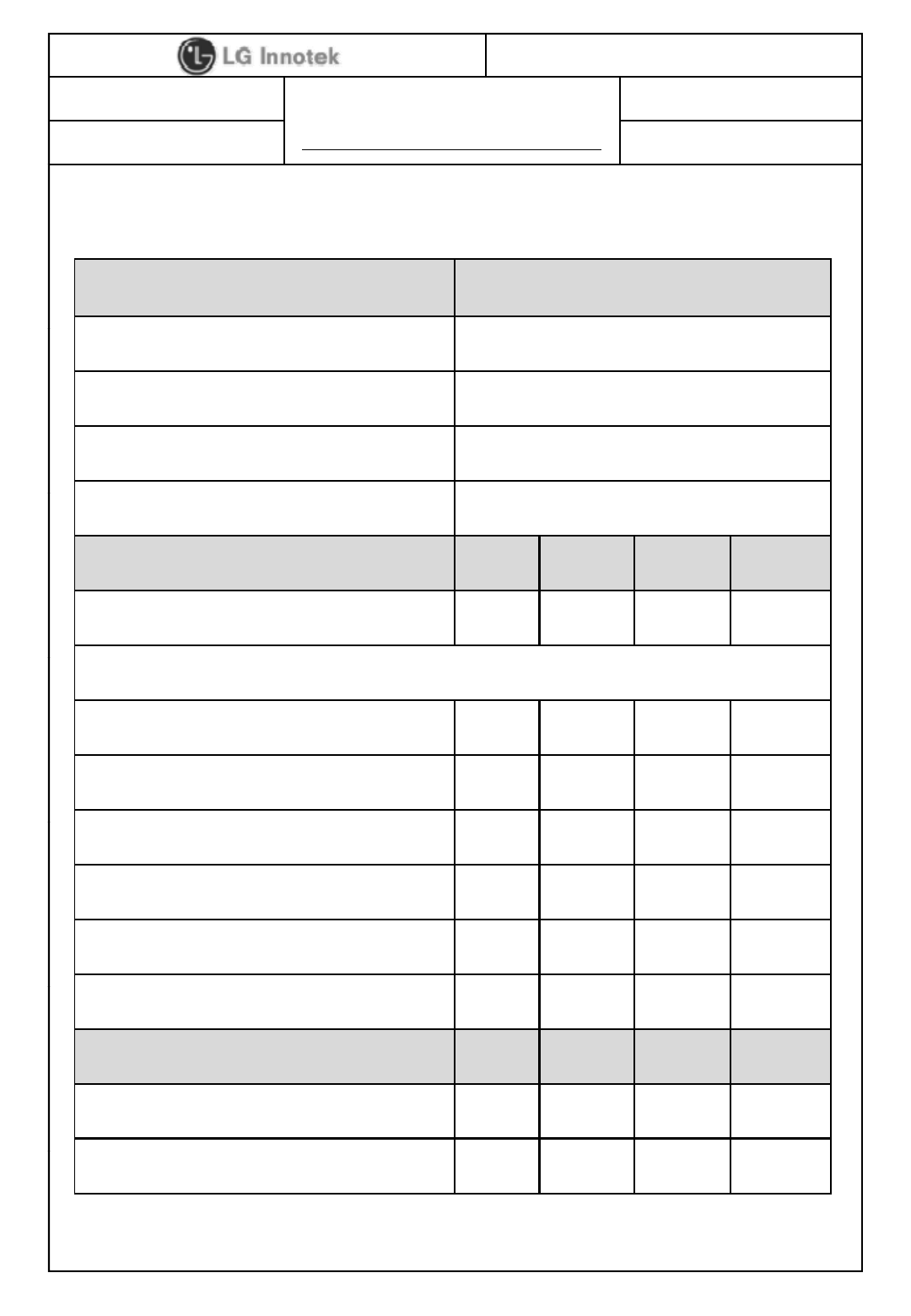
7-1. RF Characteristics for IEEE802.11b ( 11Mbps mode unless otherwise specified)
Specification IEEE802.11b
Mode DSSS/CCK
Channel frequency 2412 ~ 2462 MHz
Data rate 1,2,5.5,11Mbps
TX Characteristics Min. Typ. Max. Unit
Power Level(AVG) 10 12 14 dBm
Spectrum Mask
1st side lobes - - -30 dBr
2nd side lobes - - -50 dBr
Modulation Accuracy (EVM) - - 35 %
Power On/Off ramp -2.0 - 2.0 Usec
Freq. Tolerance -25 0 25 ppm
Chip Clock Freq. Tolerance -25 0 25 ppm
RX Characteristics Min. Typ. Max. Unit
Minimum Input Level Sens. (FER ≤ 8%) -88 -76 dBm
Maximum Input Level (FER ≤8%)
10
dBm
©2013 LGIT. All rights reserved.
Maximum
Input
Level
(FER
≤
8%)
-
10
--
dBm
* Normal Condition : 25℃, VDD=5V.
* RF characteristics is board limit. It can differ according to standards
S P E C I F I C A T I O N
PAGE :
DOCUMENT No : WC40006
REG. DATE : Jan. 07. 2013
MODEL NAME : TWFM-L303D-F
REV.NO : 1.0
6/ 21
REG. DATE : Jan. 07. 2013
Items Contents
7-2. RF Characteristics for IEEE802.11g ( 54Mbps mode unless otherwise specified)
Specification IEEE802.11g
Mode OFDM
Channel frequency 2412~ 2462 MHz
Data rate 6,9,12,18,24,36,48,54Mbps
TX Characteristics Min. Typ. Max. Unit
Power Level(AVG) 7.5 9.5 11.5 dBm
Spectrum Mask
at fc +/-11MHz - - -20 dBr
at fc +/-20MHz - - -28 dBr
at fc ≥ +/- 30MHz - - -40 dBr
Constellation Error (EVM) - - -25 dB
Freq. Tolerance -20 0 20 ppm
Chip Clock Freq. Tolerance -20 0 20 ppm
RX Characteristics Min. Typ. Max. Unit
Minimum Input Level Sens. (PER ≤ 10%) - -73 -65 dBm
©2013 LGIT. All rights reserved.
Maximum Input Level (PER ≤ 10%) -30 - - dBm
* Normal Condition : 25℃, VDD=5V.
* RF characteristics is board limit. It can differ according to standards
S P E C I F I C A T I O N
PAGE :
DOCUMENT No : WC40006
REG. DATE : Jan. 07. 2013
MODEL NAME : TWFM-L303D-F
REV.NO : 1.0
7/ 21
REG. DATE : Jan. 07. 2013
Items Contents
Specification
IEEE802 11n
24GHz
7-3. RF Characteristics for IEEE802.11gn ( MCS7 mode unless otherwise specified)
- HT20MHz Data Rate is 65Mbps, HT40MHz Data Rate is 135Mbps
Specification
IEEE802
.
11n
–
2
.
4GHz
Mode OFDM
Channel frequency 2412 ~ 2462 MHz (HT20)
2422 ~ 2452 MHz (HT40)
Data rate 6.5,13,19.5,26,39,52,58.5,65Mb
p
s
p
TX Characteristics Min. Typ. Max. Unit
Power Level(AVG) / HT20 7.5 9.5 11.5 dBm
Power Level(AVG) / HT40 6.5 8.5 10.5 dBm
Spectrum Mask
at fc +/-11MHz - - -20 dBr
at fc +/-20MHz - - -28 dBr
at fc ≥ +/- 30MHz - - -45 dB
r
Constellation Error (EVM) - - -28 dB
Freq. Tolerance(HT20 / HT40) -20 0 20 ppm
Chip Clock Freq. Tolerance(HT20 / HT40) -20 0 20 ppm
RX Characteristics Min. Typ. Max. Unit
Minimum Input Level Sens.
(HT20,PER ≤ 10%) --70-64dBm
Minimum Input Level Sens.
(HT40,PER
≤
10%)
--67-62dBm
©2013 LGIT. All rights reserved.
(HT40,PER
10%)
Maximum Input Level (PER ≤ 10%) -30 - - dBm
* Normal Condition : 25℃, VDD=5V.
* RF characteristics is board limit. It can differ according to standards
S P E C I F I C A T I O N
PAGE :
DOCUMENT No : WC40006
REG. DATE : Jan. 07. 2013
MODEL NAME : TWFM-L303D-F
REV.NO : 1.0
8/ 21
REG. DATE : Jan. 07. 2013
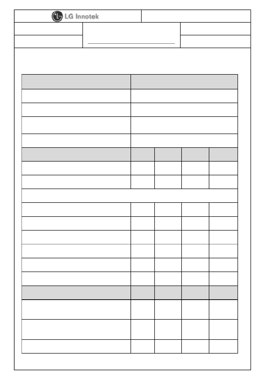
8. Mechanical Characteristics
8-1. Outline view
Item Test Conditions
8-2. Appearance structure
Assembly No defects of wiring, soldering and assembling
Appearance No dirt, rust, corrosion or foreign material
Item Test Conditions
Dimension As outline drawing
Mounting As outline drawing
Weight
Approximately 4 75
±
04[g]
Weight
Approximately
4
.
75
±
0
.
4
[g]
©2013 LGIT. All rights reserved.
S P E C I F I C A T I O N
PAGE :
DOCUMENT No : WC40006
REG. DATE : Jan. 07. 2013
MODEL NAME : TWFM-L303D-F
REV.NO : 1.0
9/ 21
REG. DATE : Jan. 07. 2013
9. Software
9-1. Windows Utility
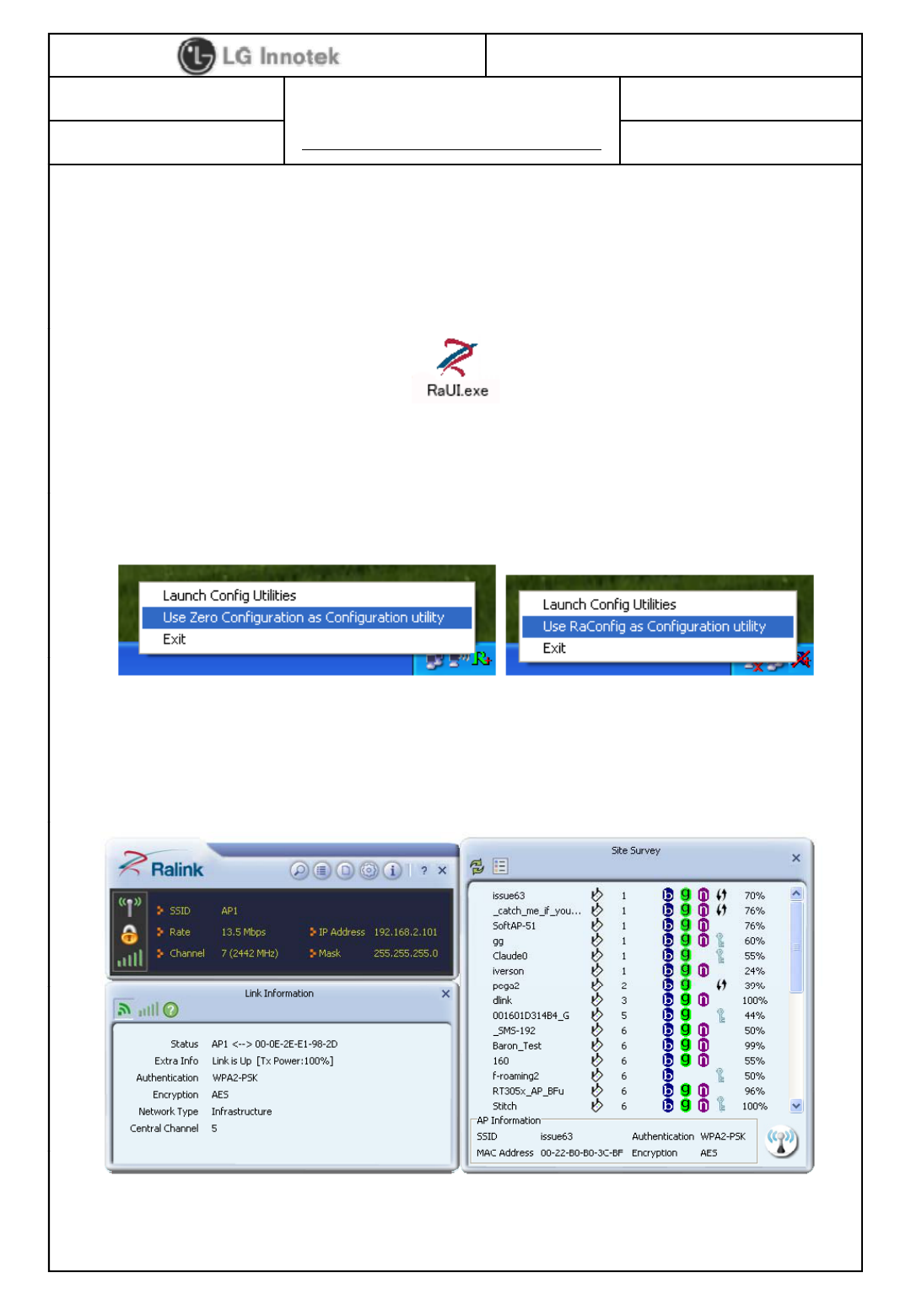
Execute the released windows utility installer.
(1) Run RaUI.exe
(2) RaUI can co-exist with WZC. When coexisting with WZC, RaUI only provides
monitoring functions such as surveying the link status network status static
< Fig1.1 RaUI icon>
monitoring
functions
,
such
as
surveying
the
link
status
,
network
status
,
static
counters, advanced features status, WMM status and WPS status.
(3) When starting RaUI, the system will connect to the AP with best signal
strength without setting a profile or matching a profile setting. It will issue
a scan command to a wireless NIC. After two seconds, the AP list will be
updated with the results of a BSS list scan.
< Fig1.2 Select WZC and RaUI>
©2013 LGIT. All rights reserved.
< Fig1.3 RaUI section introduction>
S P E C I F I C A T I O N
PAGE :
DOCUMENT No : WC40006
REG. DATE : Jan. 07. 2013
MODEL NAME : TWFM-L303D-F
REV.NO : 1.0
10 / 21
REG. DATE : Jan. 07. 2013
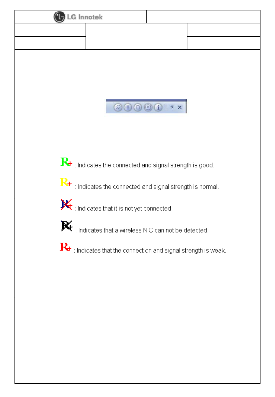
(4) Button section.
- Site survey, Link information, Profile, Advanced, Information, About page.
- Help page.
(5) When starting RaUI, a small Ralink icon appears in the notifications area of
the taskbar as shown in <Fig1 5>
< Fig1.4 Button section>
the
taskbar
,
as
shown
in
<Fig1
.
5>
.
* Please refer to the help page in detail usage manual.
< Fig1.5 Ralink icon in system tray>
9-2. Linux Device Driver
Before compiling the driver, you should change make file or makefile.inc to meet
your target platform.
* Please refer to the release note in detail.
©2013 LGIT. All rights reserved.

S P E C I F I C A T I O N
PAGE :
DOCUMENT No : WC40006
REG. DATE : Jan. 07. 2013
MODEL NAME : TWFM-L303D-F
REV.NO : 1.0
11 / 21
REG. DATE : Jan. 07. 2013
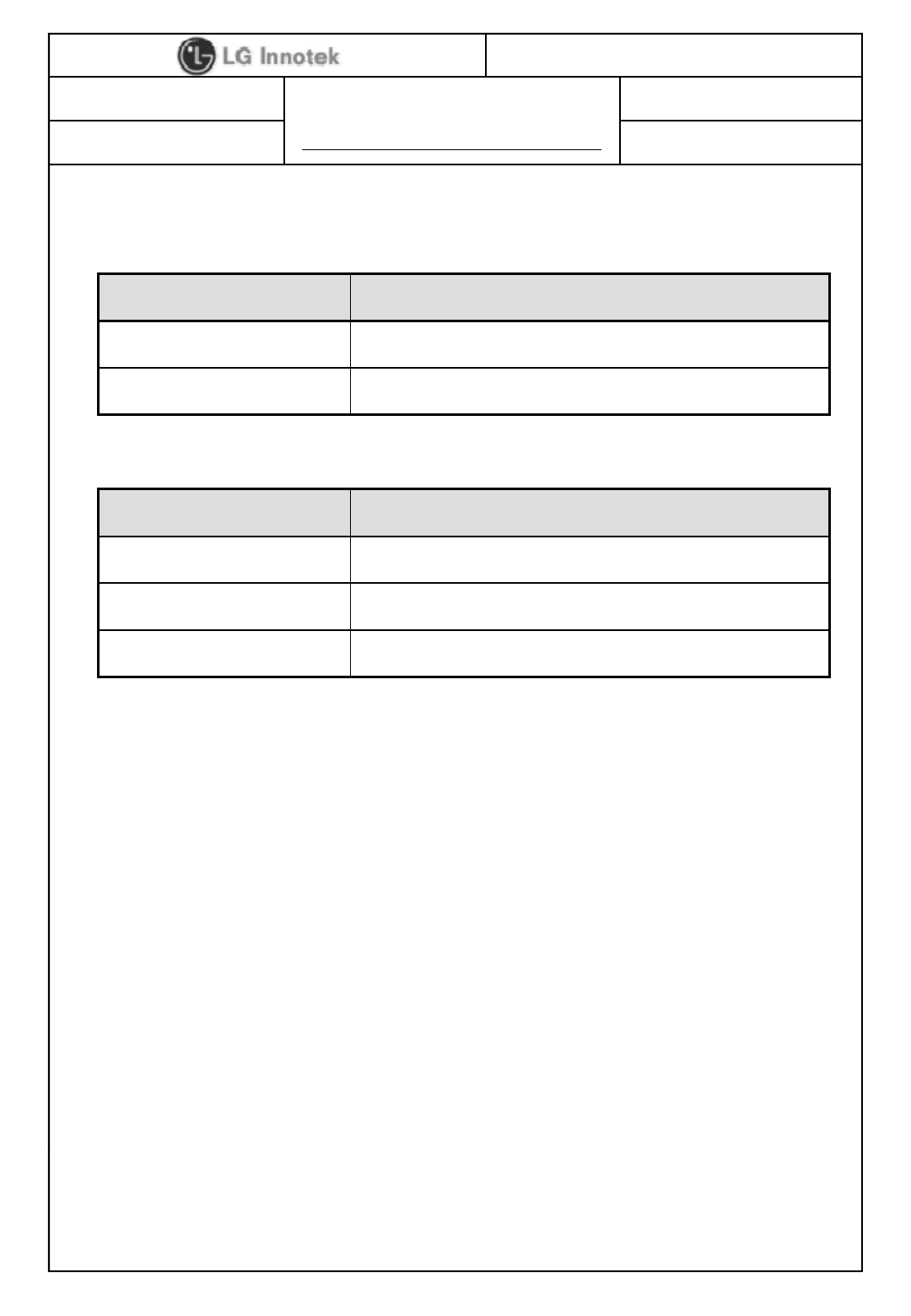
10. Environment Tests
Item Test Conditions Specifications
Initial values are measured at standard test condition.
Lli60
℃
±
2
℃
f96
±
5h di
Heat Load
Test
L
eave samp
l
es
i
n
60
℃
±
2
℃
f
or
96
±
5
h
ours, an
d
i
n
standard test condition for 30 minutes, then take
measurements within 1 hour.
- Supply voltage : standard ±5%
Initial values are measured at standard test condition.
Humidity
Load Test
Leave samples in 40℃±5℃, 90% RH for 96 ±5
hours, and in standard test condition for 30 minutes,
then take measurements within 1 hour.
- Supply voltage : standard + 5%
Iitil l d t t d dt t diti
• Power Level
: ±4dB Max
• Min. Input
Level Sens.
:
±
4dB Max
Cold Test
I
n
iti
a
l
va
l
ues are measure
d
a
t
s
t
an
d
ar
d
t
es
t
con
diti
on.
Leave samples in -20℃±2℃for 96 ±5 hours, and
in standard ambient for 1 hour with standard power
Supply then take measurements within 1 hour.
T
a
k
e
m
easu
r
e
m
e
nt
s
in
s
t
a
n
da
r
d
t
es
t
co
n
d
iti
o
n.
:
±
4dB
Max
Temperature
Shock
a e easu e e s s a da d es co d o
Temp. : -40℃~ +85℃
Duration : 30 min
Ramp-up & Ramp-down for 5 min
Cycle : 100cycle.
Vibration
Test
Initial value measure at standard test condition.
Sweep rate : 1 single sweep/ minute
Amplitude : 1.5 mm
Frequency : 10-55Hz
Duration : 1 Hours per direction (X,Y,Z)
©2013 LGIT. All rights reserved.
ESD
Test
Initial values are measured at standard test condition.
- Wafer (USB Connector) : ±500V, 10 times
- Antenna & Cover : ±1kV, 10times
S P E C I F I C A T I O N
PAGE :
DOCUMENT No : WC40006
REG. DATE : Jan. 07. 2013
MODEL NAME : TWFM-L303D-F
REV.NO : 1.0
12 / 21
REG. DATE : Jan. 07. 2013
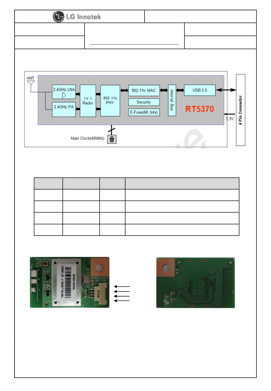
11. Block Diagram
12. Pin Description
Pin No. Pin Name I/O Pin Description
1
VDD
I
VDD 3 3V
1
VDD
I
VDD
3
.
3V
2 USB_DN I/O USB Communication signal USB_DN
3 USB_DP I/O USB Communication signal USB_DP
4 GND - GND
①
②
Note.
1) Recommend a Module install sequence for prevent USB device failure
< Top View >
②
③
④
< Bottom View >
©2013 LGIT. All rights reserved.
- Supply 3.3V power
- Connect to data signal (USB_DP, USB_DN)
2) If remove the module, proceed in inverse sequence
3) Connector : 12507WR-04L(YEON HO)
S P E C I F I C A T I O N
PAGE :
DOCUMENT No : WC40006
REG. DATE : Jan. 07. 2013
MODEL NAME : TWFM-L303D-F
REV.NO : 1.0
13 / 21
REG. DATE : Jan. 07. 2013
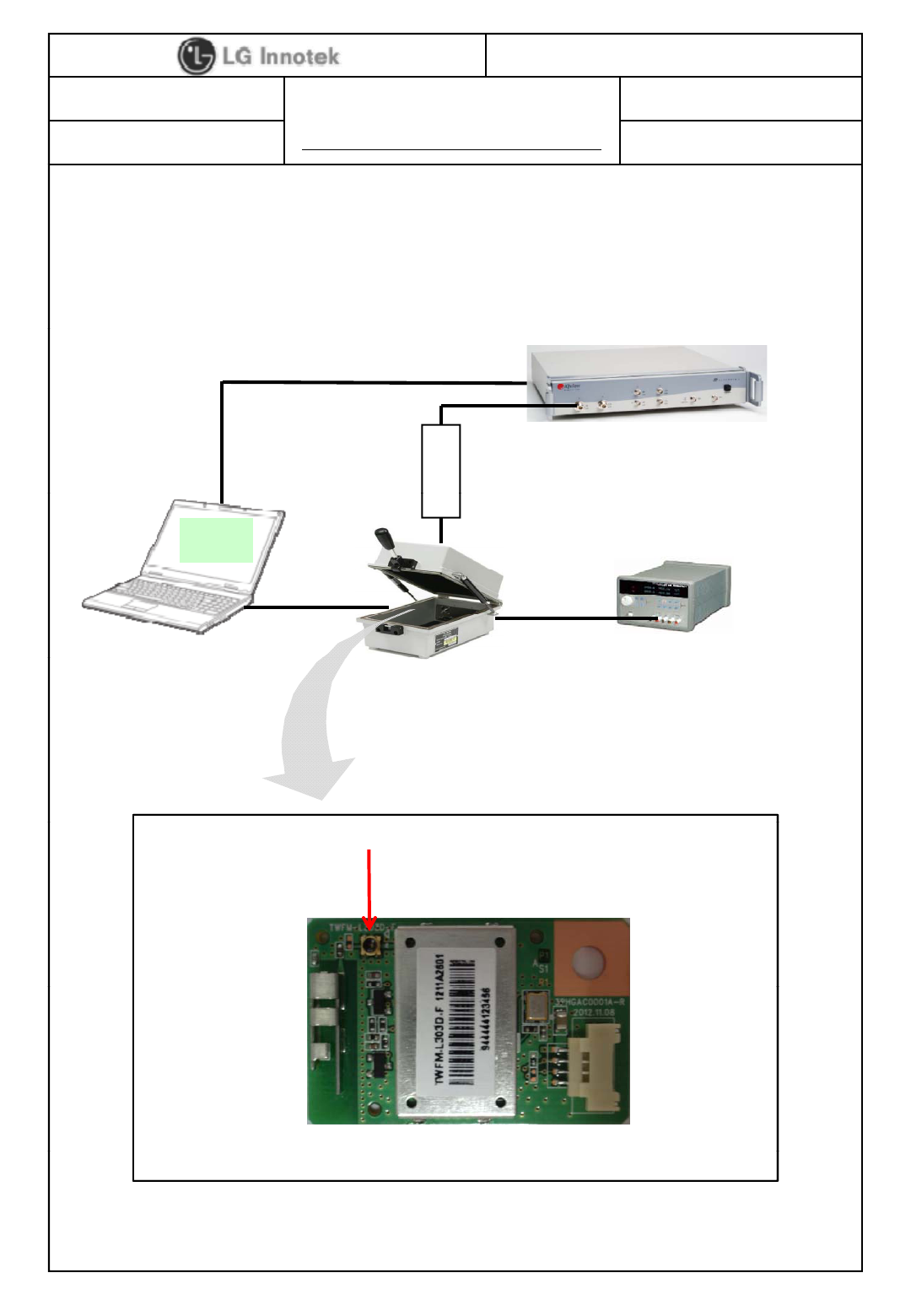
13. Test Method
This is a conducted test method of Wi-Fi RF performance.
13-1. Test Condition.
a
nuator
LitePoint IQnxn or IQflex
R
F Cable
LAN Cable
Power Su
pp
l
y
TESCOM
Att
a
Auto test
Program
USB Cable Power 3.3V
R
pp y
TESCOM
Shield Box
( TC-5910DP)
RF Connector
( I-PEX MHF-SW23)
©2013 LGIT. All rights reserved.

S P E C I F I C A T I O N
PAGE :
DOCUMENT No : WC40006
REG. DATE : Jan. 07. 2013
MODEL NAME : TWFM-L303D-F
REV.NO : 1.0
14 / 21
REG. DATE : Jan. 07. 2013
13-2. Test Set-up List.
-. Instrument : LitePoint IQnxn or IQflex
-. Shield Box : Tescom TC-5910DP
-
Driver Version : 5 102 98 12
.
Driver
Version
:
5
.
102
.
98
.
12
-. RF Cable : TESCOM 4011-0011
-. Attenuator : Mini-Circuit 15542 10dB attenuator
-. USB Cable, LAN Cable, RF Cable(I-PEX MHF-SW23)
-. Power Supply
13-3. Test Flow
-. Install the test set-up.
-. Power OFF.
-. Open the Shield box and install the DUT for test.
-. Close the shield box.
-. Power ON.
-. Check the driver icon.
-. Start testing.
# Notes
#
.
Notes
.
-. Be careful that you can consider a RF cable LOSS.
©2013 LGIT. All rights reserved.
S P E C I F I C A T I O N
PAGE :
DOCUMENT No : WC40006
REG. DATE : Jan. 07. 2013
MODEL NAME : TWFM-L303D-F
REV.NO : 1.0
15 / 21
REG. DATE : Jan. 07. 2013
14. Outline Drawing
©2013 LGIT. All rights reserved.
S P E C I F I C A T I O N
PAGE :
DOCUMENT No : WC40006
REG. DATE : Jan. 07. 2013
MODEL NAME : TWFM-L303D-F
REV.NO : 1.0
16 / 21
REG. DATE : Jan. 07. 2013
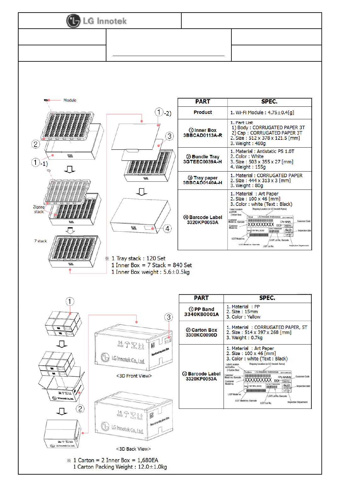
15. Packing Information
1) Inner Packing
2) Carton Box Packing
©2013 LGIT. All rights reserved.
S P E C I F I C A T I O N
PAGE :
DOCUMENT No : WC40006
REG. DATE : Jan. 07. 2013
MODEL NAME : TWFM-L303D-F
REV.NO : 1.0
17 / 21
REG. DATE : Jan. 07. 2013
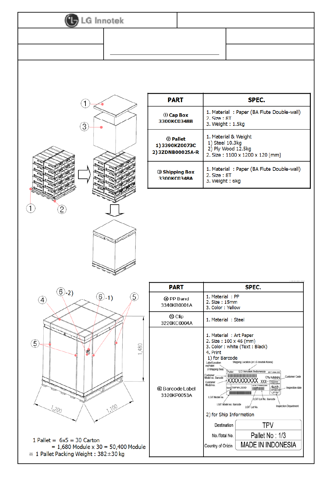
3) Pallet Packing
©2013 LGIT. All rights reserved.
S P E C I F I C A T I O N
PAGE :
DOCUMENT No : WC40006
REG. DATE : Jan. 07. 2013
MODEL NAME : TWFM-L303D-F
REV.NO : 1.0
18 / 21
REG. DATE : Jan. 07. 2013
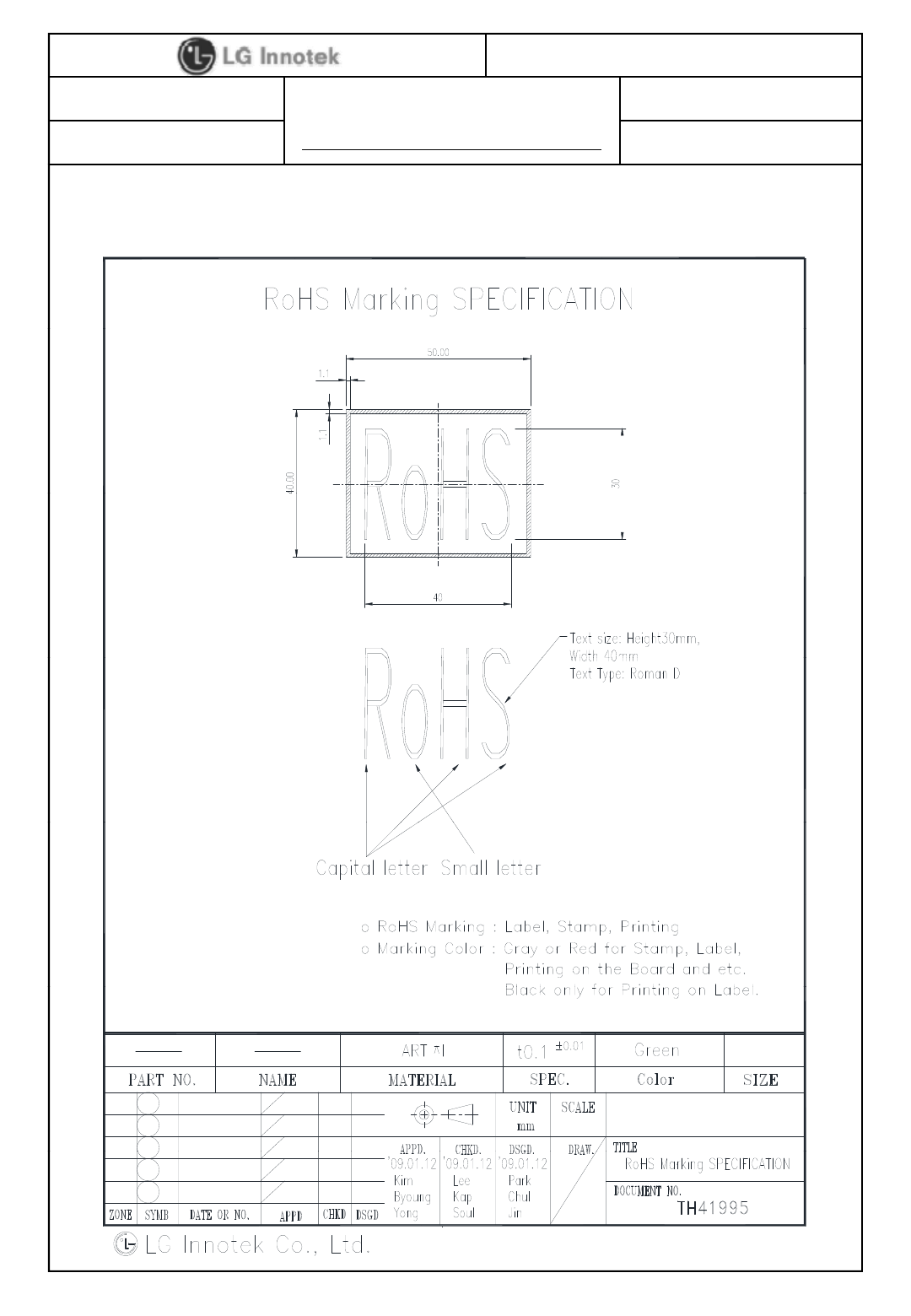
3) RoHS Marking
©2013 LGIT. All rights reserved.
S P E C I F I C A T I O N
PAGE :
DOCUMENT No : WC40006
REG. DATE : Jan. 07. 2013
MODEL NAME : TWFM-L303D-F
REV.NO : 1.0
19 / 21
REG. DATE : Jan. 07. 2013
16. Change History of Revision
Revision Date Contents of Revision Change Remark
1.00 13. 01. 07 1) First release K. H. Choi
©2013 LGIT. All rights reserved.
S P E C I F I C A T I O N
PAGE :
DOCUMENT No : WC40006
REG. DATE : Jan. 07. 2013
MODEL NAME : TWFM-L303D-F
REV.NO : 1.0
20 / 21
REG. DATE : Jan. 07. 2013
1) Features
# Appendix
1. Antenna Characteristics
Antenna Performance
Parameter Min Typ Max Unit
Frequency Range 2412 2445 2485 MHz
Directivity - Omni - -
Average Gain - -1.29 -
dBi
dBi
Peak Gain 1.84
V.S.W.R - 2.0:1 - Under
Impedance 50 Ohm
Radiation Material Tin plate
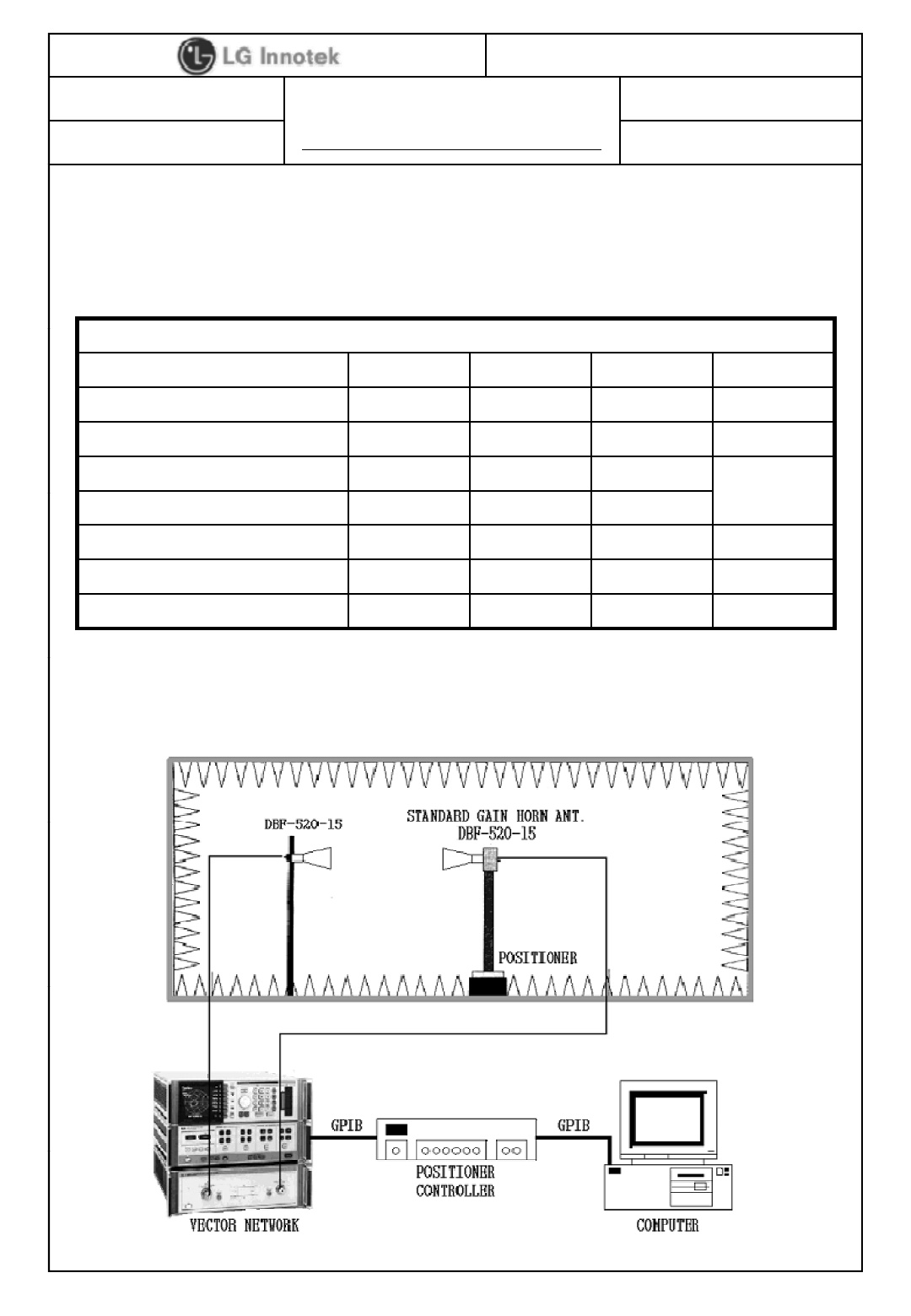
2) Test condition
- OTA 3D Chamber
©2013 LGIT. All rights reserved.
S P E C I F I C A T I O N
PAGE :
DOCUMENT No : WC40006
REG. DATE : Jan. 07. 2013
MODEL NAME : TWFM-L303D-F
REV.NO : 1.0
21 / 21
REG. DATE : Jan. 07. 2013
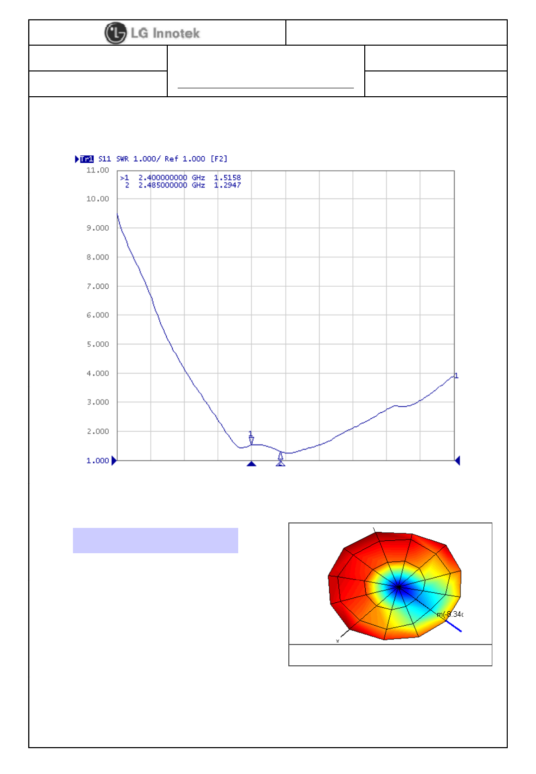
a. VSWR
b. Gain
Freq Gavg Gpeak
MHz dBi dBi deg
c. Radiation Pattern
2412 -2.05 1.68 90
2450 -1.00 1.62 90
2485 -1.13 1.64 90
2450MHz
©2013 LGIT. All rights reserved.

User Information
The satisfy FCC exterior labeling requirements, the following test must be placed on the exterior of the end product.
Contains Transmitter module FCC ID: YZP-TWFML303D
This device complies with FCC radiation exposure limits set fo rth for an un controlled environment. This device should be installed and ope rated with minim um distance 20cm
between the radiating element of this device and the user. This device must not be co-located or operating in conjunction with any other antenna or transmitter.
This device is intended only for OEM integrators and following statements shall be included to host user manual
1) The antenna must be installed such that 20cm is maintained between the antenna and users.
2) This module may not be co-located with any other transmitters or antennas.
As long as 2 condition s above are me t, further tran smitter test w ill not be required. However, the OEM integrator is still res ponsible for testi ng their end-prod uct for a ny
additional compliance requirements with this module installed. In the event that these co nditions cannot be met, then the FCC a uthorizations are no longer considered valid and
the FCC ID cannot be u sed on the final produ ct. In these circu mstances, the OEM integrat or will be re sponsible for re-evalu ating the end produ ct including this mod ule and
obtaining separate FCC authorizations.
This equipment has been tested and found to comply with the limits for a Class B digital device, pursuant to Part 15 of the FCC Rules. These limits are designed to
provide reasonable protection against harmful interference in a residential installation. This equipment generates uses and can radiate radio frequency energy and, if not installed
and used in accordance with the instructions, may cause harmful interference to radio communications.
However, there is no guarantee that interference will not occur in a particular installation. If this equipment does cause harmful interference to radio or
television reception, which can be determined by turning the equipment off and on, the user is encouraged to try to correct the interference by one or more of the
following measures:
– Reorient or relocate the receiving antenna.
– Increase the separation between the equipment and receiver.
– Connect the equipment into an outlet on a circuit different from that to which the receiver is connected.
– Consult the dealer or an experienced radio/TV technical for help.
– Reorient or relocate the receiving antenna.
– Increase the separation between the equipment and receiver.
– Connect the equipment into an outlet on a circuit different from that to which the receiver is connected.
– Consult the dealer or an experienced radio/TV technical for help.
This device complies with Part 15 of the FCC`s Rules. Operation is subject to the following two Conditions:
1. This device may not cause harmful interference, and
2. This device must accept any interference received, including interference that may cause undesirable operation.
G Innotekdeclares that this TWFM-L303D-F is compliance with the essential requirements and other relevant provisions of directive 1999/5/EC.
This equipment may generate or use ra dio frequency energy. Changes or modifications to this equipment may cause harmful interference unless the modifications are expressly
approved in the instruction manual. The user could lose the authority to operate this equipment if an unauthorized change or modification is made.