LG LRSPC2661T User Manual REFRIGERATOR Manuals And Guides L0301008
LG Side by Side Refrigerator Manual L0301008 LG Side by Side Refrigerator Owner's Manual, LG Side by Side Refrigerator installation guides
User Manual: LG LRSPC2661T LRSPC2661T LG REFRIGERATOR - Manuals and Guides View the owners manual for your LG REFRIGERATOR #LRSPC2661T. Home:Kitchen Appliance Parts:LG Parts:LG REFRIGERATOR Manual
Open the PDF directly: View PDF ![]() .
.
Page Count: 77

WARNINGS AND PRECAUTIONS FOR SAFETY
Please observe the following safety precautions in order to
use safely and correctly the refrigerator and to prevent
accident and danger during repair.
1. Be care of an electric shock. Disconnect power cord
from wall outlet and wait for more than three minutes
before replacing PWB parts. Shut off the power
whenever replacing and repairing electde components.
2. When connecting power cord, please wait for more than
five minutes after power cord was disconnected from the
wall outlet.
3. Please check if the power plug is pressed down by the
refrigerator against the wall tf the power plug was
damaged, it may cause fire or electric shock.
4. ff the wall outlet is over loaded, it may cause fire. Please
use its own individual electrical outlet for the refrigerator.
5. Please make sure theoutlet is propedy earthed,
particularlyin wet or damp area.
6, Use standard electrical components when replacing
them.
7. Make sure the hook is correctly engaged.
Remove dust and foreign matedals from the housing
and connecting parts.
8. Do notfray. damage, machine, heavily bend, pull out,
or twist the power cord.
Please check the evidence of moisture intrusion in the
electrical components. Replace the parts or mask it
with insulation tapes if moisture intrusion was
confirmed.
10. Do not touch the icomaker with hands or tools to
confirm the operation of geared motor.
11. Do not let the customers repair, disassemble, and
reconst_ct the refdgerator for themselves. It may
cause accident, electTic shock, or fire.
12. Do not store flammable materials such as ether,
benzene, alcohol, chemicals, gas, or medicine in the
refrigerator.
13. Do not put flower vase, cup, cosmetics, chemicals,
etc., or container with full of water on the top of the
refrigerator.
14. Do not put glass bottles with full of water into the
freezer. The contents shall freeze and break the glass
bottles.
15. When you scrap the refrigerator, please disconnect the
door gasket first and scrap it where children are not
accessible.
-3-
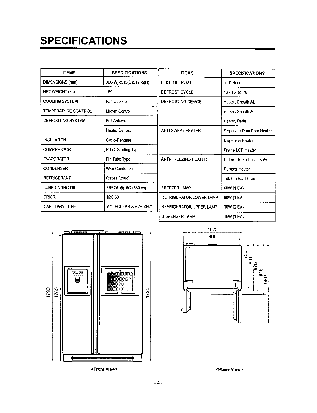
SPECIFICATIONS
ITEMS
DIMENSIONS (ram)
NET WEIGHT (kg)
COOLING SYSTEM
TEMPERATURE CONTROL
DEFROSTING SYSTEM
SPECIFICATIONS
960(W)x915(D)×1795(H)
169
Fan Cooling
MicomControl
FullAutomatic
Heater Defrost
Cyclo-Pentane
P,T.C, Starting Type
Fin Tube Type
Wire Condenser
R134a (210g)
FREOL @15G (330 cc)
1_0.83
MOLECULAR SIEVE XH-7
ITEMS
FIRST DEFROST
DEFROST CYCLE
DEFROSTING DEVICE
INSULATION
COMPRESSOR
EVAPORATOR
CONDENSER
REFRIGERANT
LUBRICATING OIL
DRIER
CAPILLARY TUBE
<Front View>
ANTI SWEAT HEATER
ANTI-FREEZING HEATER
FREEZER LAMP
REFRIGERATOR LOWER LAMP
REFRIGERATOR UPPER LAMP
DISPENSER LAMP
1072
SPECIFICATIONS
5-6 Hours
13- 15 Hours
Heater, Sheeth-AL
Heater, Sheatb-ML
Heater, Drain
Dispenser Duct Door Heater
Dispenser Heater
Frame LCD Heater
Chilled Room DuctHeater
Damper Heater
Tube Inject Heater
60W (1 EA)
60W (1 EA)
30W (2 EA)
i15W(1 EA)
<Plane View>
L
i
!
I
i
-4-
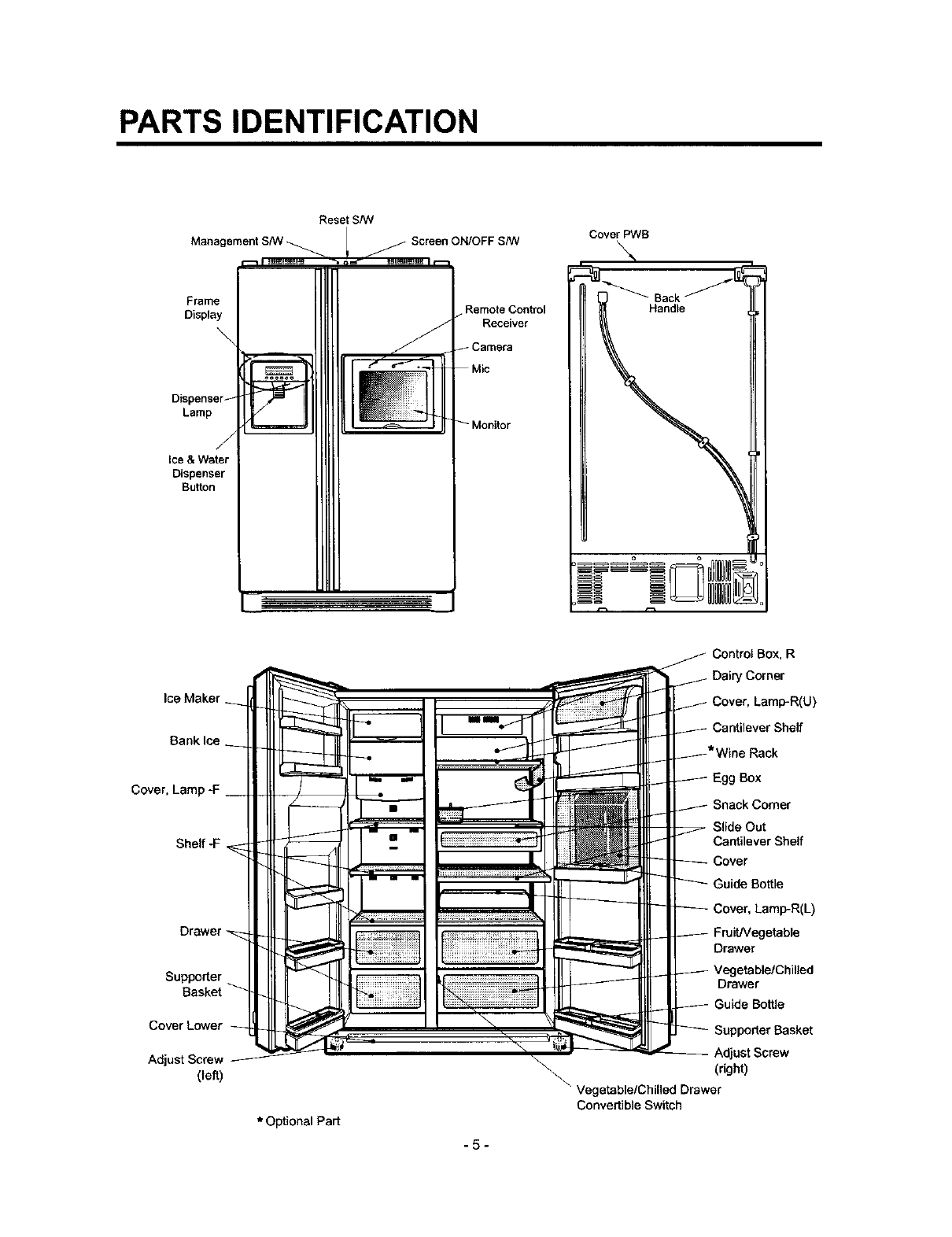
PARTS IDENTIFICATION
Manag
Reset S/W
Cover PWB
Frame
Display
Lamp
Ice &Water
Dispenser
Button
Remote Control
Receiver
Camera
Banklce
Control Box, R
Dairy Corner
Cover, Lamp-R(U)
Cantilever Shelf
Cover,
Shelf-F
Supporter
Basket
Cover Lower
Adjust Screw
(left)
Egg Box
Snack Comer
Slide Out
Cantilever Shelf
Cover
Guide Bottle
Cover, Lamp-R(L)
FruiUVegetable
Drawer
Drawer
Bottle
\\
AdjustScrew
(right)
Vegetable/Chilled Drawer
Convertible Switch
*Optional Part
.5-

HOW TO INSTALL REFRIGERATOR
1. How to Adjust Door Height of Refrigerator
•Make the refrigerator level first. (ff the refrigerator is not installed on the fiat floor, the height of freezer and refrigerator
door may not be the same.)
1. If the height of freezer door is lower than that of
refrigerator compartment :
2. If the height of freezer door is higher than that of
refrigerator compartment :
Insert a driver B into the groove A of edjusting screw
and rotate driver in arrow direction (clockwise) until the
refrigerator becomes horizontal.
Insert a ddver B into the groove A of adjusting screw
and rotate driver in arrow direction (clockwise) until the
refrigerator becomes horizontal.
-6-
HOW TO INSTALL REFRIGERATOR
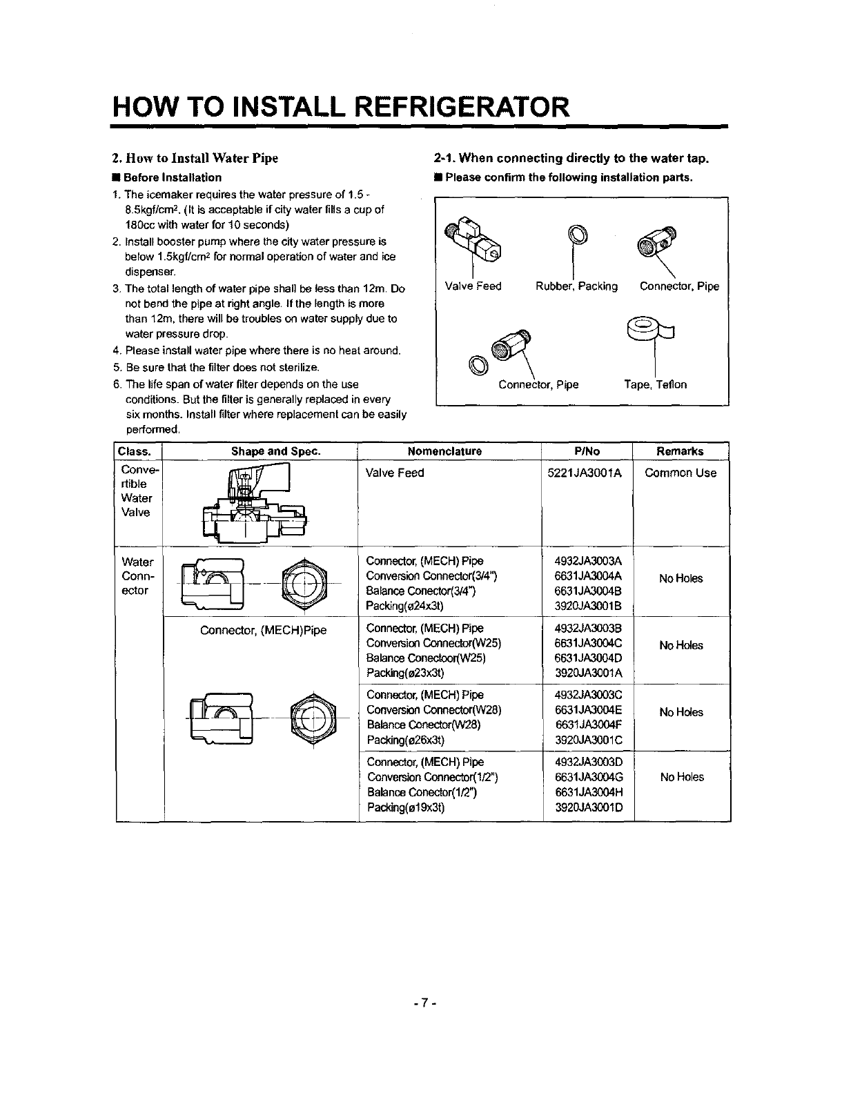
2. How to Install Water Pipe
•Before Installation
t. The icemaker requires the water pressure of 1.5 -
8.5kgf/cm 2. (It is acceptable if city water fills a cup of
180cc with water for 10 seconds)
2. Install booster pump where the city water pressure is
below 1.5kgf/cr_- for normal operation of water and ice
dispenser.
3. The total length of water pipe shall be less than 12rn. Do
not bend the pipe at right angle. If the length is more
than 12m. there will be troubles on water supply due to
water pressure drop.
4. Please install water pipe where there is no heat around.
5. Be sure that the filter does not sterilize.
6. The life span of water filter depends on the use
conditions. But the filter is generally replaced in every
six months. Install filter where replacement can be easily
performed,
2-1. When connecting directly to the water tap.
•Please confirm the following installation parts.
Valve Feed Rubber, Packing Connector, Pipe
Connector, Pipe Tape, Teflon
Class. Shape and Spec. Nomenclature PINo Remarks
Conve- _. [_"_ Valve Feed 5221JA3001A Common Use
rtible
Water
Valve
Water _ Q 4932JA3003A
Conn- _____ 6631JA3004A No Holes
ector 6631JA3004B
3920JA3001 B
Connector, (MECH)Pipe
No Holes
Connector,(MECH)Pipe
ConversionConnector(3/4")
BalanceConector(3/4")
Packing(o24x3t)
Connector,(MECH) Pipe
ConversionCeenector(W25)
BalanceConectcor(W25)
Packing(a23x3t)
Connector,(MECH)Pipe
ConversionConnector(W28)
BalanceConector(W28)
Packing(e26x3t)
Connector,(MECH)Pipe
ConversionConnector(I/2")
BalanceConector(1/2")
Packing(ol 9x3t)
4932JA3003B
6631JA3004C
6631JA3004D
3920JA3001A
4932JA3(X)3C
6631JA3004E No Holes
6631JA3004F
3920JA3001C
No Holes
4932JA3003D
6631JA3004G
6631JA3004H
3920JA3001D
-7-
HOW TO INSTALL REFRIGERATOR
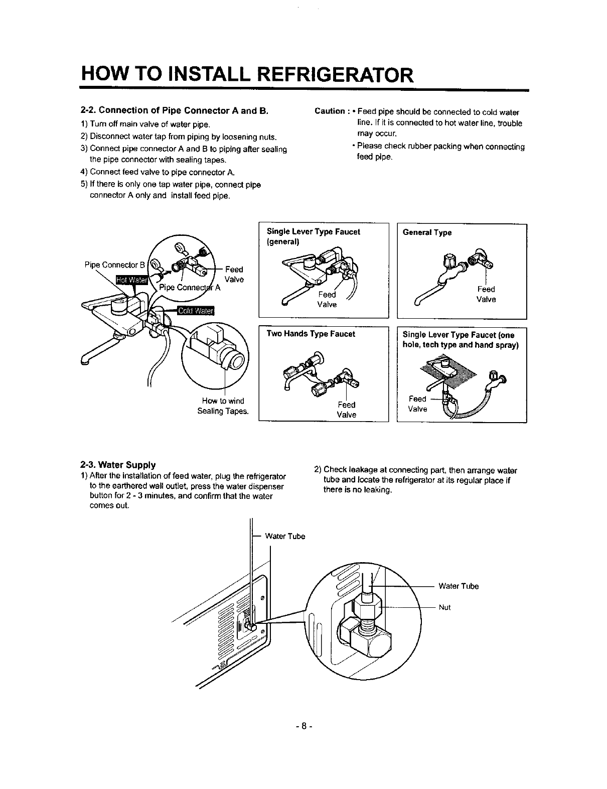
2-2. Connection of Pipe Connector A and B.
1) Turn off main valve of water pipe.
2) Disconnect water tap from piping by loosening nuts.
3) Connect pipe connector A and B to piping alter sealing
the pipe connector with sealing tapes.
4) Connect feed valve to pipe connector A.
5) If there is only one tap water pipe, connect pipe
connector A only and install feed pipe.
Caution : oFeed pipe should be connected to cold water
line. If it is connected to hot water line, trouble
may occur.
• Please check rubber packing when connecting
feed pipe.
Pipe Connector B Feed
\A
How to wind
SealingTapes.
Single Lever Type Faucet
(general)
Two Hands Type Faucet
Feed
Valve
Gene_lType
Feed
Valve
Single LeverTypeFaucet(one
hole, techtypeand hand spray)
Valve
2-3. Water Supply
1) After the installation of feed water, plug the refrigerator
to the earthered wall outlet, press the water dispenser
button for 2- 3 minutes, and confirm that the water
comes out.
2) Check leakage at connecting part, then arrange water
tube and locate the refrigerator at its regular place if
there is no leaking.
-8-
HOW TO INSTALL REFRIGERATOR
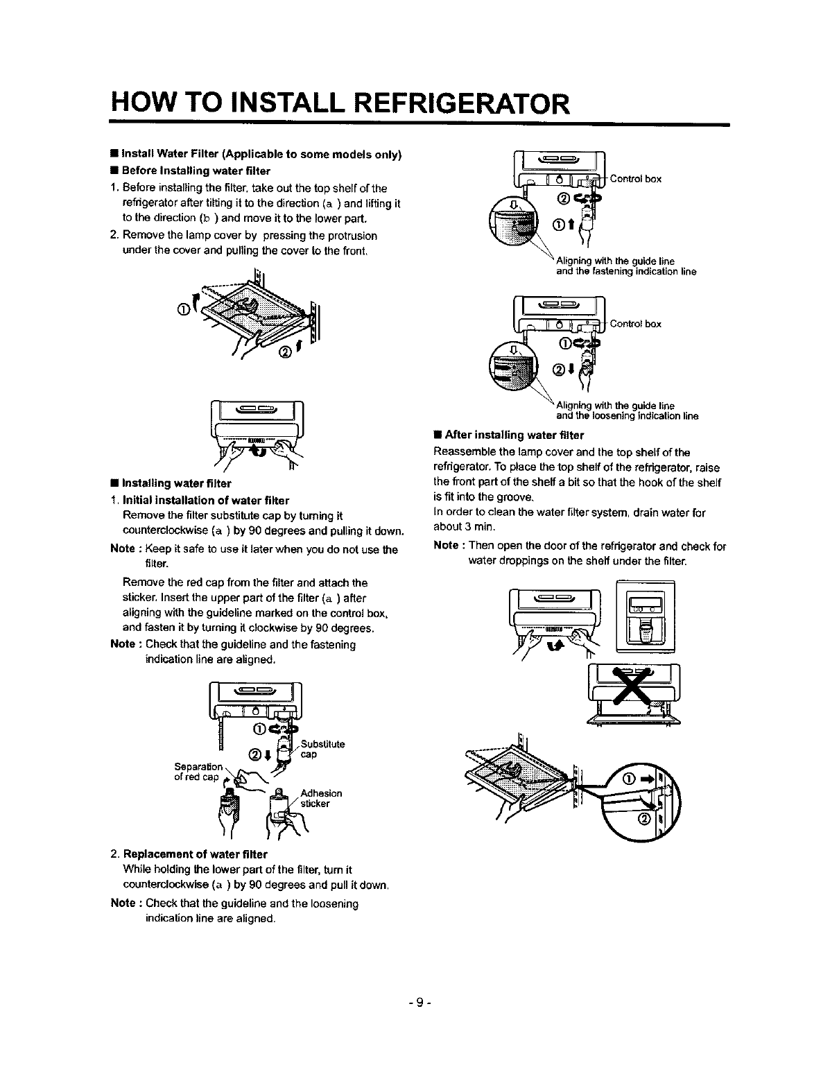
•Install Water Filter (Applicable to some models only)
•Before Installing water filter
1. Before installing the filter, take out the top shelf of the
refrigerator after tilting it to the direction (a) and lifting it
to the direction (b) and move it to the lower part.
2. Remove the lamp cover by pressing the protrusion
under the cover and pufiing the cover to the front.
•Installing water filter
1. Initial installation of water filter
Remove the filter substitute cap by turning it
counterclockwise (a) by 90 degrees and pulling it down.
Note : Keep it safe to use it later when you do not use the
filter.
Remove the red cap from the filter and attach the
sticker, Insert the upper part of the filter (a) after
aligning with the guideline marked on the control box,
and fasten it by turning it clockwise by 90 degrees.
Note : Check that the guideline and the fastening
indication line are aligned.
_ubstitute
_=_= Adhesion
_ _icker
2. Replacement of water filter
While holding the lower part of the filter, turn it
counterclockwise (a) by 90 degrees and pull it down.
Note : Check that the guideline and the loosening
indication line are aligned.
Control box
guide line
and the fastening indication line
JI
O_i ;ontrolbox
"" " the guide line
and the loosening indication line
•After installing water filter
Reassemble the lamp cover and the top shelf of the
refrigerator. To place the top sheff of the refrigerator, raise
the front part of the shelf a bit so that the hook of the shelf
is fit into the groove.
In order to clean the water filter system, drain water for
about 3 min.
Note : Then open the door of the refrigerator and check for
water droppings on the shelf under the filter.
-9-
HOW TO INSTALL REFRIGERATOR
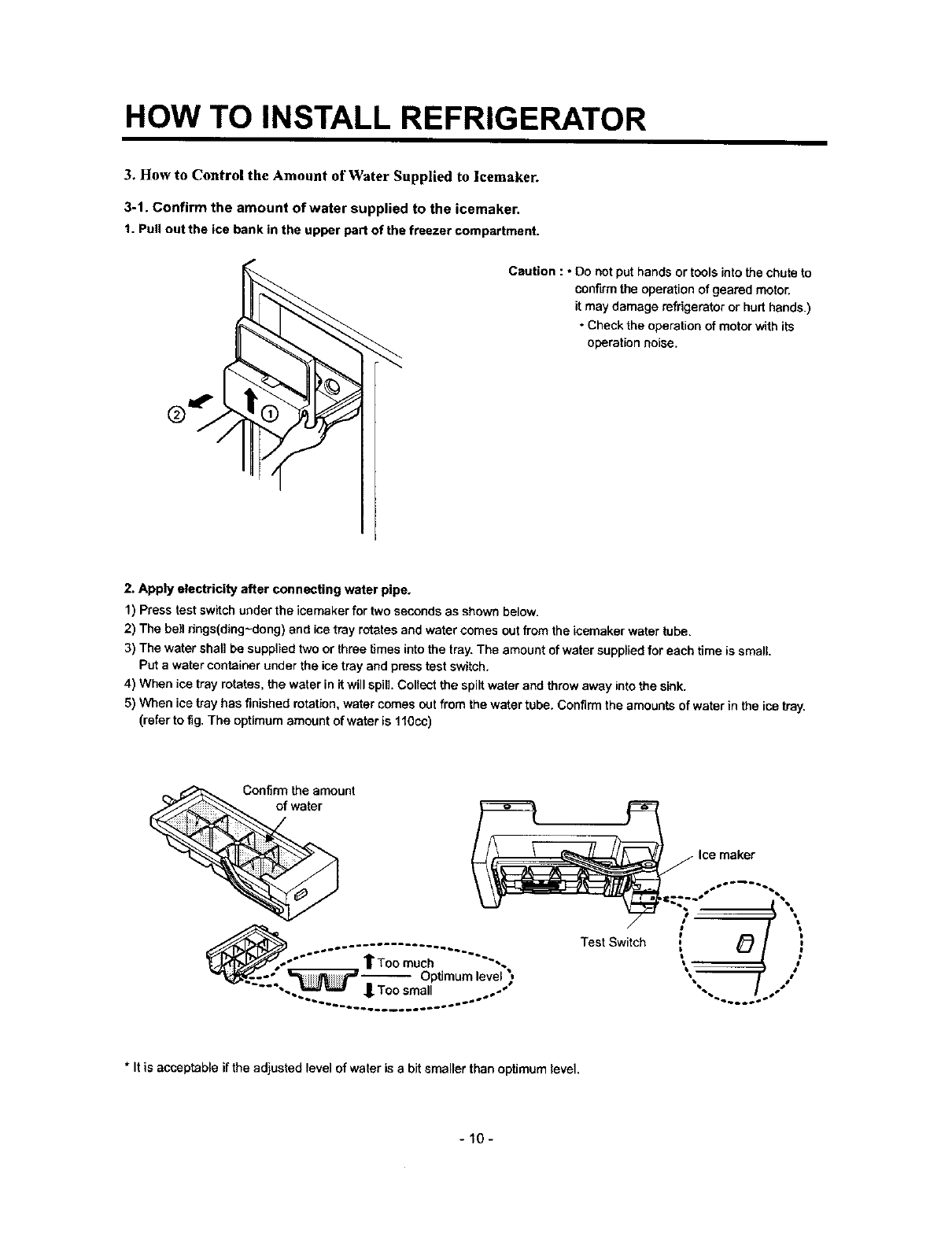
3. How to Control the Amount of Water Supplied to icemaker.
3-1. Confirm the amount of water supplied to the icemaker.
t. Pull out the ice bank in the upper pert of the freezer compartment.
Caution : * Do not put hands or tools into the chute to
confirm the operation of geared motor.
it may damage refrigerator or hurt hands.)
•Check the operation of motor with its
operation noise.
2. Apply electricity after connecting water pipe.
1) Press test switch under the icemaker for two seconds as shown below.
2) The bell rings(ding-dong) and ice tray rotates and water comes out from the icemaker water tube.
3) The water shall be supplied two or three times into the tray. The amount of water supplied for each time is small
Put a water container under the ice tray and press test switch.
4) When ice tray rotates, the water in it will spill. Collect the spilt water and throw away into the sink.
5) When ice tray has finished rotation, water comes out from the water tube. Confirm the amounts of water in the ice tray.
(refer to fig. The optimum amount of water is 110cc)
Confirm the amount
of water
Test Switch
Ice maker
i '
*It is acceptableiftheadjusted level of water is a bit smaller than optimumlevel.
-10-
HOW TO INSTALL REFRIGERATOR
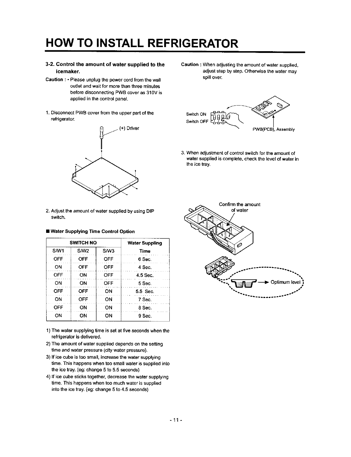
3-2. Control the amount of water supplied to the
icemaker.
Caution : •Please unplugthe powercordfrom thewall
outletand waitfor more than three minutes
before disconnectingPWS coveras 310V is
appliedin thecontrolpanel,
1. Disconnect PWB cover from the upper part of the
refrigerator.
j(+) Driver
Caution : When adjusting the amount of water supplied,
adjust step by step. Otherwise the water may
spill over.
Switch ON
Switch OFF
PWB(PCB), Assembly
3. When adjustment of control switch for the amount of
water supplied is complete, check the level of water in
the ice tray.
2, Adjust theamountof water suppliedby usingDIP
switch.
Confirm the amount
of water
• Water Supplying Time Control Option
SWITCH NO Water Suppling
S/W1 SNV2 S/W3 Time
OFF OFF OFF 6Sec.
ON OFF OFF 4 Sec.
OFF ON OFF 4.5 Sec.
ON ON OFF 5 Sec.
OFF OFF ON 5.5 Sec.
ON OFF ON 7Sec.
OFF .... ON ON ..... 8Sec.
ON ON ON gSec.
Optimumle ,"
"'_b_ _o_ SS
1) The water supplying time is set at five seconds when the
refrigerator is delivered.
2) The amount of water supplied depends on the setting
time and water pressure (city water pressure).
3) If ice cube is too small, increase the water supplying
time. This happens when too small water is supplied into
the ice tray. (eg: change 5 to 5.5 seconds)
4) If ice cube sticks together, decrease the water supplying
time. This happens when too much water is supplied
into the ice tray. (eg: change 5 to 4.5 seconds)
-11 -
ICEMAKERANDDISPENSEROPERATIONPRINCIPLEANDREPAIRMETHOD
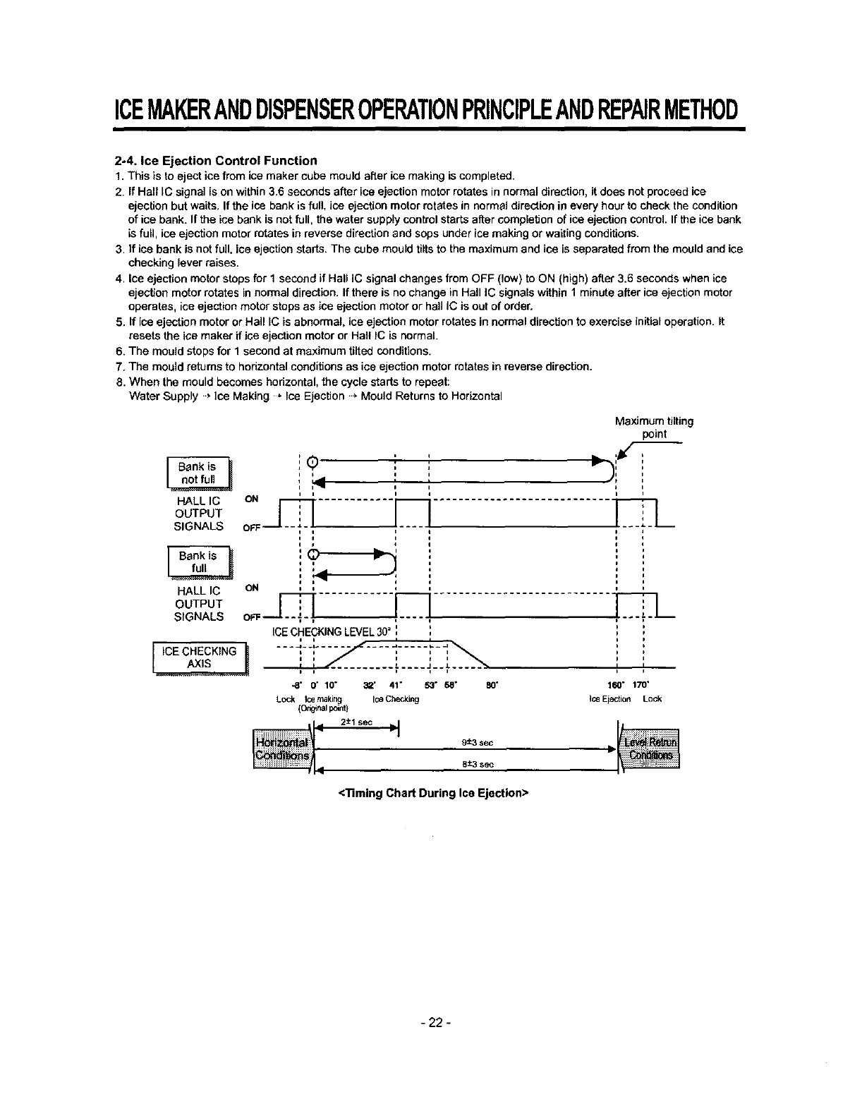
2°4. Ice Ejection Control Function
1. This is to eject ice from ice maker cube mould after ice making is completed.
2. if Hall IC signal is on within 3.6 seconds after ice ejection motor rotates in normal direction, it does not proceed ice
ejection but waits, If the ice bank is full ice ejection motor rotates in normal direction in every hour to check the condition
of ice bank. If the ice bank is not full, the water supply control starts after completion of ice ejection control. If the ice bank
is full, ice ejection motor rotates in reverse direction and sops under ice making or waiting conditions.
3. if ice bank is not full, ice ejection starts. The cube mould tilts to the maximum and ice is separated from the mould and ice
checking lever raises.
4. Ice ejection motor stops for 1 second if Hall IC signal changes from OFF (low) to ON (high) after 3.6 seconds when ice
ejecSon motor rotates in normal direction. If there is no change in Hall IC signals within 1 minute after ice e}ection motor
operates, ice ejection motor stops as ice ejection motor or hall IC is out of order.
5. If ice ejection motor or Hall IC is abnormal, ice ejection motor rotates in normal direction to exercise initial operation. It
resets the ice maker if ice ejection motor or Halt IC is normal.
6. The mould stops for 1 second at maximum tilted conditions.
7. The mould returns to horizontal conditions as ice ejection motor rotates in reverse direction.
8. When the mould becomes horizontal, the cycle starts to repeat:
Water Supply ..* Ice Making *Ice Ejection .._Mould Returns to Horizontal
r Bank is
HALL IC
OUTPUT
SIGNALS
Bank is "_
HALL IC
OUTPUT
SIGNALS
IICE CHECKING
Maximum tilting
point
o ' ' =-)'/'
• , r
ii i
i1_ IIi
, ,,
OFF
ON
ICECHECKING LEVEL 30° i I
i p / I i t
.... L.... J__J.
t t t i i
-8' O" 10" 32' 41" 53" 68" 80'
Lock Ice making Ice Checking
(o_n_ i:,_nt)
2±1 sec =I
9:_3 sec
I I
160" 170'
IceEjection Lock
L
8+-3sac IL
<Timing Chart During Ice Ejection>
-22 -

ICEMAKERANDDISPENSEROPERATIONPRINCIPLEANDREPAIRMETHOD
2-5 Test Function
1. It is to force the operation during operation test, service, and cleaning. The test switch is mounted under the automatic
ice maker. The test function starts when the test switch is pressed for more than 0.5 second.
2. Test button does not work during ice ejection and water supply. It works when it is in the horizontal conditions. If mould is
full of ice during test function operation, ice ejection control and water supply control do not work.
3. When test switch is pressed for more than 0.5 second in the horizontal conditions, ice ejection starts irrespect of the
mould conditions. Water shall be splashed it test switch is pressed before the water in the mould freezes. Water shall be
supplied while the mould returns to the horizontal conditions after ice ejection. Therefore the problems of ice ejection,
returning to the horizontal conditions, and water supply can be checked by test switch. When test function performs
normally, buzzer sounds and water supply shall carry out. Check it for repair if buzzer does not sound.
4. When water supply is completed, the cycle operates normally as follows: Ice making • Ice ejection •Returning to
horizontal conditions , Water supply
5. Remove ice from the ice maker cube mould and press test switch when ice maker cube mould is full of ice as ice ejection
and water supply control de not work when cube mould is full of ice.
2-6. Other functions relating to freezer compartment door opening
1, When freezer door is open, ice dispenser steps in order to reduce noise and ice drop.
2. When freezer door is open during ice ejection and cube mould returning to horizontal condition, ice ejection and cube
mould level return proceed.
3. When freezer door is open, geared motor and cube ice solenoid immediately stop and duct door solenoid stops after 5
seconds.
4. Water dispenser stops in order to protect water drop when freezer door is open.
5. Test function operates normally irrespect of refogearator cempadment door opening.
- 23 -
ICEMAKERANDDISPENSEROPERATIONPRINCIPLEANDREPAIRMETHOD
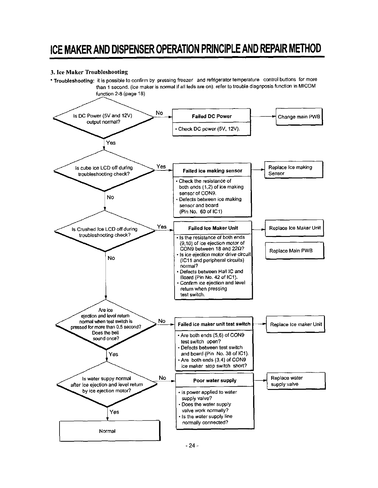
3. Ice Maker Troubleshooting
• Troubleshooting: it is possibleto confirmby pressingfreezer and refrigerator temperature controlbuttons for more
than 1 second.(ice maker is normalifall [edeare on): referto troublediagnposisfunction in MICOM
function 2-8 (page 18)
No
r
/ejesb_nand level return
/normalwhen test switch is
"_ pressed for mere than 0.5 second? /
Does the bell /
Normal
Failed DC Power
•Check DC power (5V, 12V).
_ Chang e main PWB
Failed ice making sensor
• Check the resistance of
both ends (1,2) of ice making
sensor of CON9.
• Defects between ice making
sensor and board
(Pin No. 60oflCl)
Failed Ioe Maker Unit
•Is the resistance of both ends
(9,10) of ice ejection motor of
CON9 between 18 and 22D?
• Is ice ejection motor drive circuit
(ICll and peripheral circuits)
normal?
• Defects between Hall IC and
Board (Pin No. 42 of IC1).
• Confirm ice ejection and level
return when pressing
test switch.
Replace Ice making ]
Sensor
_._ Replace Ice Maker Unit [
IReplace Main PWB I
Failed ice maker unit test switch
• Are both ends (5,6) of CON9
test switch open?
•Defects between test switch
and board (Pin No. 38 of IC1).
• Are both ends (3,4) of CON9
ice maker stop switch short?
Poor water supply
• Is power applied to water
supply valve?
•Does the water supply
valve work normally?
• Is the water supply line
normally connected?
_ Replace Ice maker Unit I
Replacewatersupplyvalve I
- 24 -
ICEMAKERANDDISPENSEROPERATIONPRINCIPLEANDREPAIRMETHOD
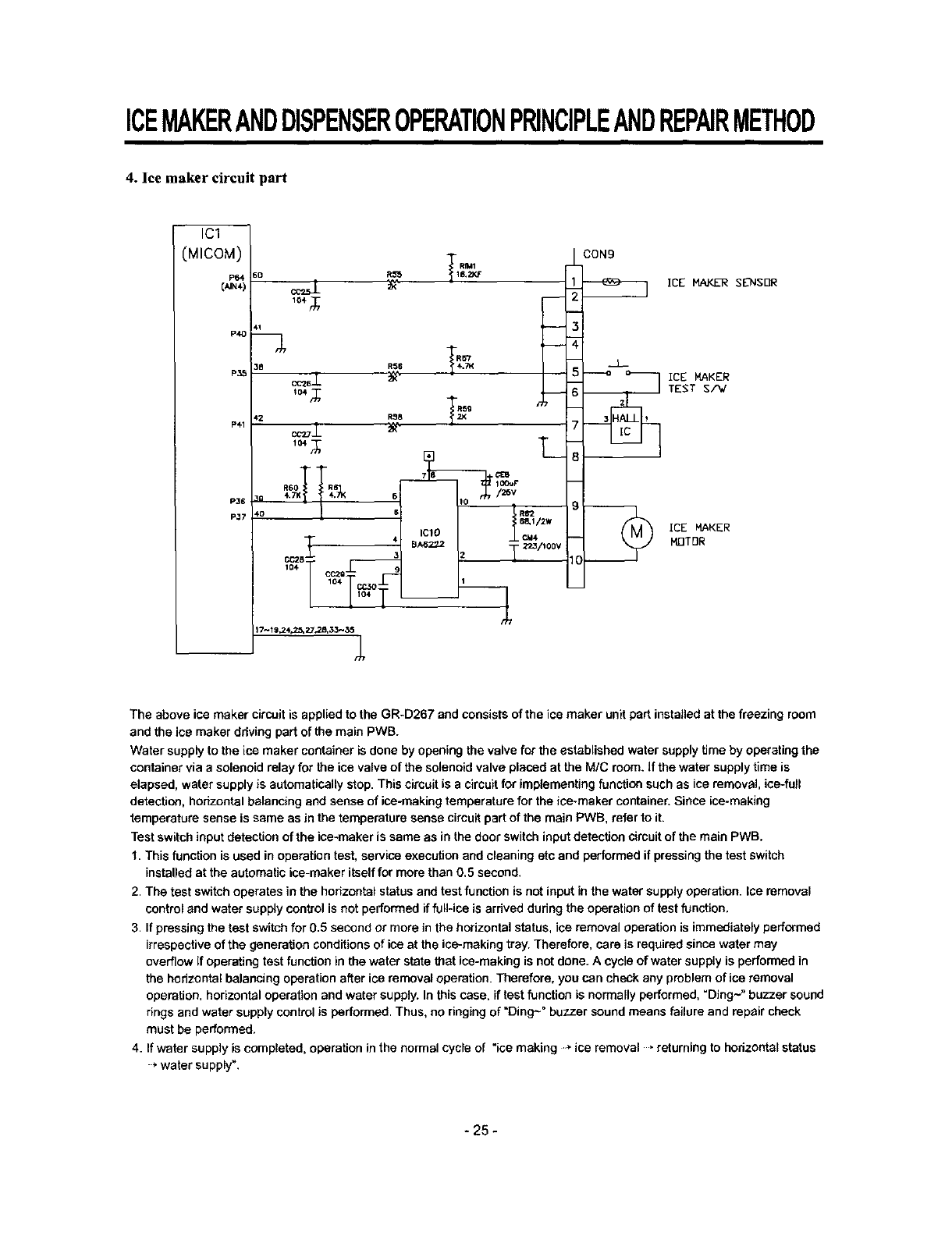
4. Ice maker circuit part
IC1
(MICOM)
P64
[,,,,_4)
P41
CON9
ICE MAKER
MOTOR
The above ice maker circuit is applied to the GR-D267 and consists of the ice maker unit pert installed at the freezing room
and the ice maker ddving part of the main PWB.
Water supply to the ice maker container is done by opening the valve for the established water supply time by operating the
container via a solenoid relay for the ice valve of the solenoid valve placed at the M/C room. If the water supply time is
elapsed, water supply is automatically stop. This circuit is a circuit for implementing function such as ice removal, ice-full
detection, horizontal balancing end sense of ice-making temperature for the ice*maker container. Since ice-making
temperature sense is same as Jnthe temperature sense circuit part of the main PWB, refer to it.
Test switch input detection of the ice-maker is same as in the door switch input detection circuit of the main PWB.
1. This function is used in operation test, service execution and cleaning etc and performed if pressing the test switch
installed at the automatic ice-maker itself for more than 0.5 second.
2. The test switch operates in the horizontal status and test function is not input in the water supply operation. Ice removal
control and water supply control is not performed if full-ice is arrived during the operation of test function.
3. If pressing the test switch for 0.5 second or more in the horizontal status, ice removal operation is immediately performed
irrespective of the generation conditions of ice at the ice*making tray. Therefore, care is required since water may
overflow if operating test function in the water state that ice-making is not done. A cycle of water supply is performed in
the horizontal balancing operation after ice removal operation. Therefore, you can check any problem of ice removal
operation, horizontal operation and water supply. In this case. if test function is normally performed, "Ding~" buzzer sound
rings and water supply control is performed. Thus, no ringing of"Ding~" buzzer sound means failure and repair check
must be performed.
4. If water supply is completed, operation in the normal cycle of "ice making -_ ice removal ,returning to hodzontst status
* water supply".
-25 -

EXPLATION FOR MICOM CIRCUIT
1. Explanation for PWB circuit
1-1. Power circuit
Power circuit consists of SMPS (SWITCHING MODE POWER SUPPLY) power. The SMPS consist of the rectifying part
(BDI, CE1) converting AC voltage to DC voltage, the switching part (IC2) switching the converted DC voltage, transformer
transferring energy of the primary side of the switching terminal to the secondary side and the feedback part (IC3. IC4)
transferring itto the primary side.
Caution : Since high voltage (DC310V) is maintained at the power terminal, please take a measure after more than 3
minutes have passed after removing power cords in the abnormal operation of a circuit.
Voltage of every part is as follows:
Voltage 230 Vac 310 Vdc 16 Vdc 12 Vdc 15.5 Vdc 5 Vdc
CONf
-34 -
EXPLATION FOR MICOM CIRCUIT
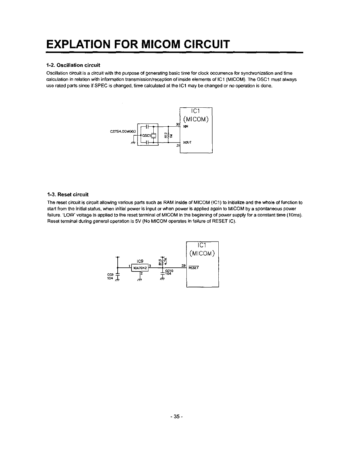
1-2. Oscillation circuit
Oscillation circuit is acircuit with the purpose of generating basic time for clock occurrence for synchronization and time
calculation in relation with information transmission/reception of inside elements of IC1 (MICOM). The OSCl must always
use rated parts since if SPEC is changed, time calculated at the IC1 may be changed or no operation is done.
CS7S4 00MGO_
ICl
(MICOM)
xeur
1-3. Reset circuit
The reset circuit is circuit allowing various parts such as RAM inside of MICOM (ICl) to initialize and the whole of function to
start from the initial status, when initial power is input or when power is applied again to MICOM by a spontaneous power
failure. 'LOW' voltage is applied to the reset terminal of MICOM in the beginning of power supply for a constant time (t Ores).
Reset terminal during general operation is 5V (No MICOM operates in failure of RESET IC).
1IC9 3_ #
IC1
(MICOM)
- 35 -
EXPLATION FOR MICOM CIRCUIT
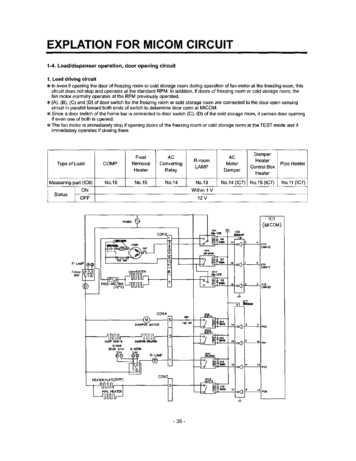
1-4. Load/dispenser operation, door opening circuit
1. Load driving circuit
In even if opening the door of freezing room or cold storage room during operation of fan motor at the freezing room, this
circuit does not stop and operates at the standard RPM. In addition, if doors of freezing room or cold storage room, the
fan motor normally operates at the RPM previously operated.
(A). (B), (C) and (D) of door switch for the freezing room or cold storage room are connected to the door open sensing
circuit in parallel toward both ends of switch to determine door open at MICOM.
_€Since a door switch of the home bar is connected to door switch (C), (D) of the cold storage room, it senses door opening
if even one of both is opened.
The fan motor is immediately stop if opening doors of the freezing room or cold storage room at the TEST mode and it
immediately operates if closing them.
Type of Load
vleasudng part (IC6)
Status OFF
COMP
No.16
Frost
Removal
Heater
No.15
AC
Converting
Relay
No.14
R-room
LAMP
No.13
Within 1 V
AC
Motor
Damper
No.14 (IC7)
Damper
Heater
Control Box
Heater
No.15 (IC7)
12V
Pipe Heater
No.ll (IC7)
F-LAkIP _@
)
FUSE-M_oNC_ _ L._
CON4
DAMP_ MO1"OR
_-_'1 _ _-I1 _ _Tl_t
ZDCR $/V R-DDQR
CON5
_g_2
DIS
DIB
14 _4
IIS 12
I
ICI
(MICOM)
=73
_Tt
i_11)
'_'112)
PeTZ
P6_
P03
- 36 -
EXPLATION FOR MICOM CIRCUIT
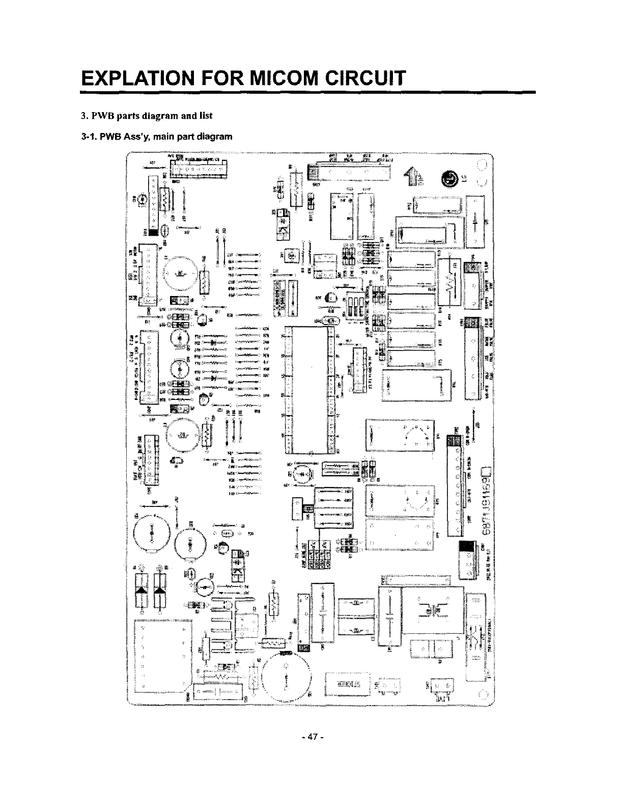
3. PWB parts diagram and list
3-1, PWB Ass'y, main part diagram
- 47 -
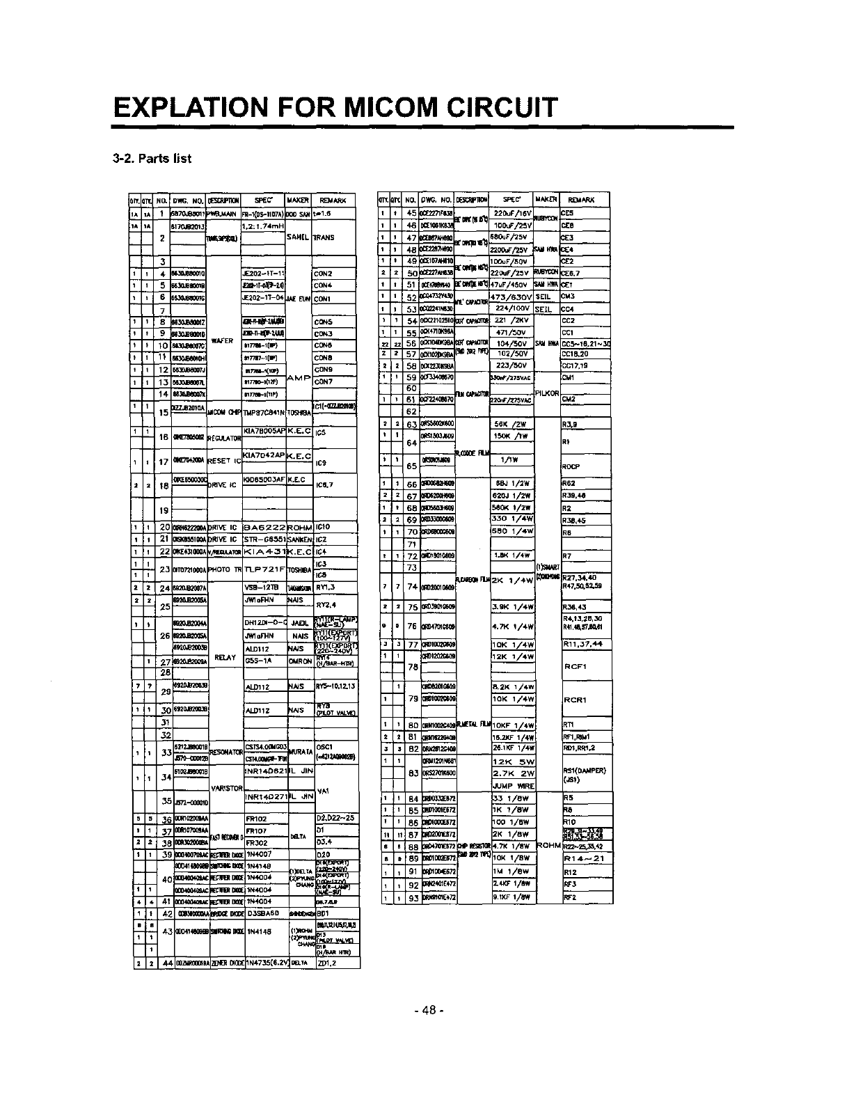
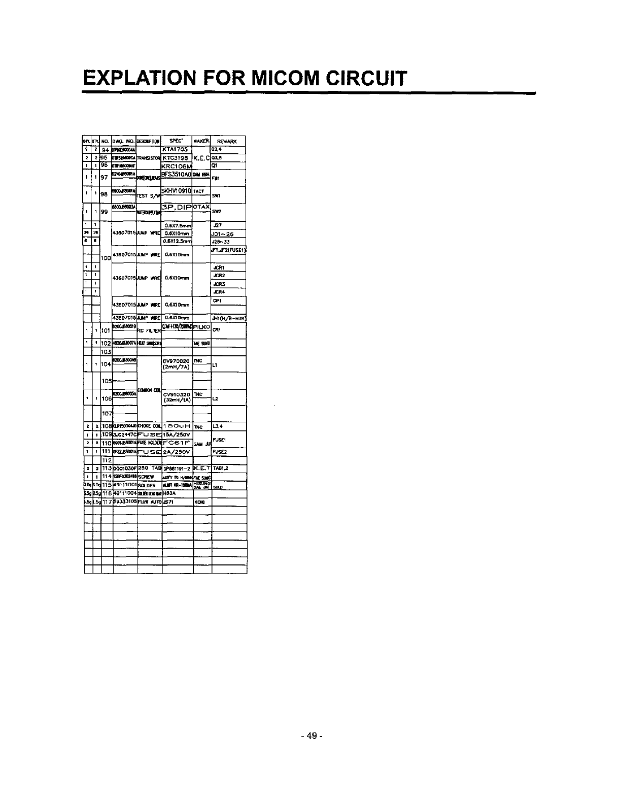
EXPLATION FOR MICOM CIRCUIT
3-2. Parts list
NO. DWG, NO. _SREC' =IAX;I_ RE_ARK
1 ;BTOJBO01? _:_B.MNN R.I_tIOTA) _00 SA_ t_1.6
M 70JOr2013 2: ?.74mH
2_ _AH[L 1R,,LNS
3
_Z3OJB_010 E202_IT-11 b'ON2
•30JB_Cma [2nF+T_,_-lt) CON+
6- }$30jg_Q_G i£302-1T-0_ ._E _CONI
7
_0 s63o,am=0 =_-_t4_ co_3
WAFER mT_-Ilr) C0N6
_,_dB_07J mT_l-t(im} _C0N9
15 IZZJB2Ot__ _COU OtP B4pagCa41N r0S_9_ Icl{'0Z_sml
KIA7BOOSAP K+E.C
16 _ ,tg{;tJ_TOH
<IA7042AP <+E,(
17 0(_R't_ _ESET IC IC9
18 -- 3RI_4_ +C IC_,7
19--
_0 '_21MB_D36: ALD11Z N_ RY_
tF*ILOTVAL_E
3_
32
osc1
12_2.aooole CsTS4.OO_,___ MURAt^
tl0_,Jl_l_B =NRt_B2 IL_ JIN
_R_ST_
37 )ORlO_ 3(107 O1
_8 _ _/_/_ _R302 aa.TA D3,4
,*I11BItJ_l_; IN400+
4_ _ __D3S_A6O _BD1
,43 30m141_4_ ;II_'I_ IN4148 1_ mJ_li'l_'tt
_400_Ol_/ _ B_( N47_5(6.2' _._A ZD1,2
ITt NO+ O'h_, NO. _i_St_JF]_(_ SF4[C" dAKL'11 RI_4,t_K
+5 :[2271F¢3_ ;'_KOII_ 220uF/16V UE'R_ CE5
46 :I_tKLX_ 100uF/25V CIEB
48 _;'_o _ocuF/25v _1 _ c_4
_ 49 _t_lO t'Oeqllll_ oouFi50v C_2
z5_ _t_._ !20uF/zsv _ CE6,7
51 0CE_R_ r_e_E_*_iF7uF/460v _tH_E?
_:_241N8]_ 224,/1QOV ;EIL CC4
1_4, 0C_21Q2510 _C_I]_ _21 /2KV CC2
_55 _<+____ +71/.',ov CCl
2 58 _(22.301(_ 223/50V ;C17,1g
1 59 O_P_670 3¢_'/_7swc CMI
6O
62
-- 64--
165 _1/IW tocP
66 _SB_ 1/2W t6Z
z 67 _1t0_ 620J 1/2W 139.4_
+6B E560(4 t/2w E2
6g _330 I/4W t38,43
170 m5BO 1/4W le
73 [l_'_T
7 74 _1_01_ _47,50,5_59
75 m_m_ 3,9K 1/4W 136,4,3
_4,t3,21P,_
J_77 R_I0_G_ 1OK 1/+V_ _11,37,4_
_'-78i--__ RCF1
79 1OK 1/4_, _CR1
80 Rm_ _T_ RtJ__ I_
B1 MI_O _ t+'1,mUl
B2 N2Sl_ 26.1KF 1/4_ _01.RRI,2
NI201k_ 12_<; _
_tK60 2._K 2"_, _:SI(DAMPER)
-- :.s_)
JUMp WlRE
84 B_2ES,_ 33 1/8W _5
_5 R51g_4{57_ 1K 1/8w _8
86 _0too_z 1<:o 1/sw _10
It 87 _2K 1/8W
_188 ;4;_72 PIPRE_5]_ 4,7K 1/8W ROHM _'_2_42
91 1_1004E672 1M 1/OW R12
-48 -
EXPLATION FOR MICOM CIRCUIT
94 _;<TAt 705 i0_4
95 _ _ <TC31S_ K.E,( 13.s
96 _,'RC106_ _--
97 _eeem/:o_=R,IZa pFS3510A( s._4_ _1
98 ooo.18_Bo_Jr_ST S,i_ ;KHV1091C TACt ;Vn
99 _--m_ _P,DIFOTAX =_r2
0.6X7,Smrr J_7
k380701_ =M_? _1 O,6XlOmm _-_26
0.6X12.Sm.1
100 )360701_ JUMp WIRE O,6XlOmm F_'JF'2(FUSE_1
JCRI
k360707_ JUMp _O-SXlOmm
,_R4
OPt
1_60701= JUmp IA_ O.6XlO_m
_360701_ J_ v,_[ O.6XlOt_m I41{H/B-H]_
102 _o_1oo7_ I_!Is= ) T_
103
104 _3v97o02o TNC
!,_HiTA) -- .1
106 -- 12mH/t^) -- -_
10_ 3J024471 _USE 15A/250V
112
lt3 :_0103_ _50 TA_ 78811_1-2 _.E,T TAB1.1
11_ 4_111004 IIBI_ Hg3A
- 49 -
EXPLATION FOR MICOM CIRCUIT
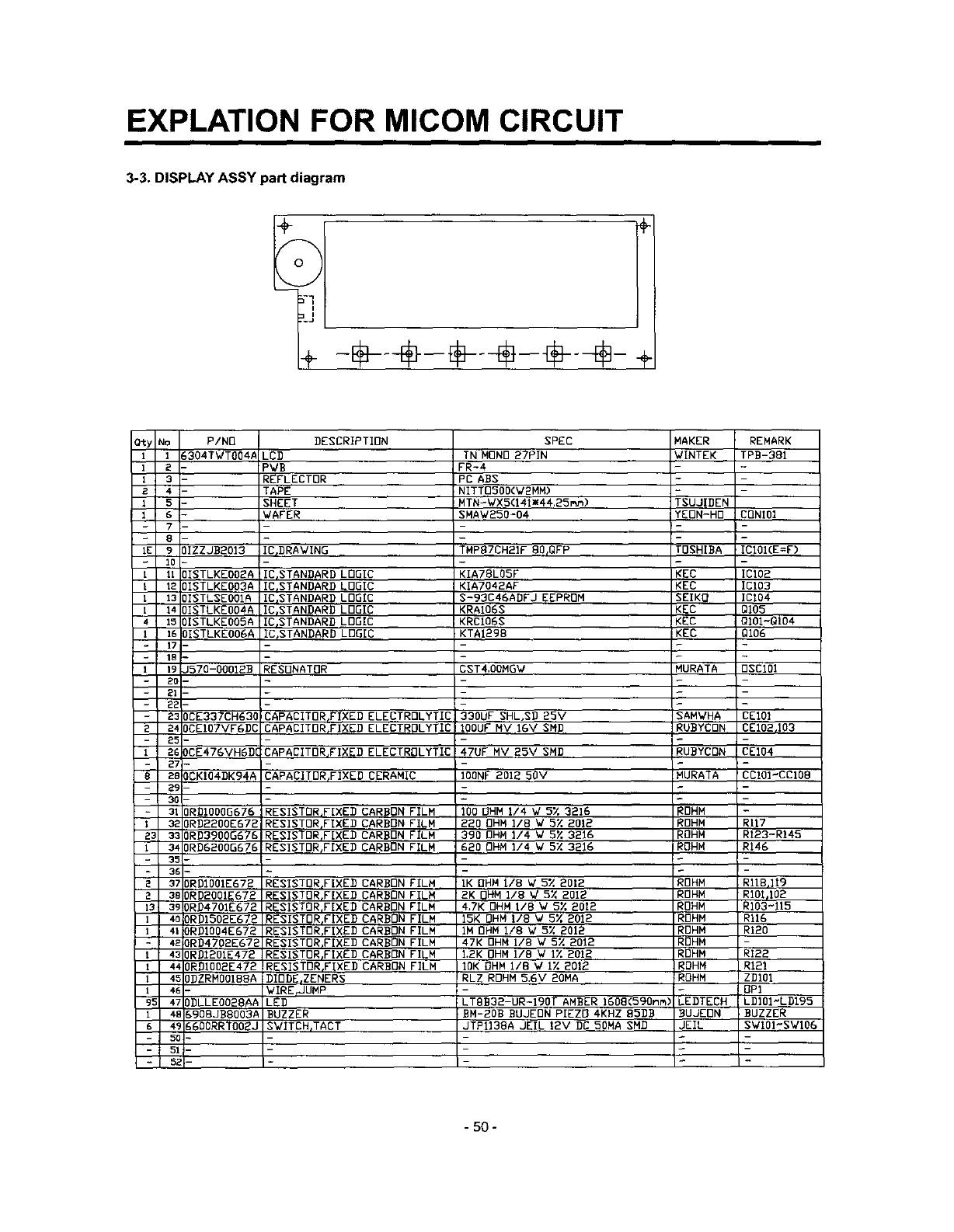
3-3. DISPLAY ASSY part diagram
O_y NO P/NO
t1 _304TWTOO4#
12
13
24
1
7
- 8
IE 9 )IZZJBBOI3
10
I 11 ]ISTLKEOOBA
I 12 IISTLKEOO3A
I 13 )ISTLSEOOIA
I 14 )ISTLKEOOAA
415 )ISTLKEOOGA
I 16 ]ISTLKEOOGA
17
- 18
I19 J570-OOOIBB
20 -
21
22
-23 DCE337CH630
2 24 OCEIO7VFGDC
- 25-
126 DCE476VHGDC
-27 -
8 2B OCKIO4DK94A
29 -
30 -
-310RDIOOOG676
1320RDBBOOE672
Z3 330RB3900G676
l340RD6200G676
35 -
-36 -
2 370RD100IE672
23BORDBOOIE672
13 390RD4701EG72
I 4o ORDIGOBE672
1410RBIOO4E672
-4_ ORD4702E672
t430RDIBOlE472
14A ORDlOO2E472
14_ OBZRMOO1BBA
I4E-
95 47 ODLLEOO28AA
t 4t _908JBBOO3A
64_ _600RRTOO_J
5CI-
51-
5zI-
DESCRIPTION SPEC
LED TN MONO 27PIN
PWB FR-4
REFLECTOR PC ABS
TAPE NITTOGOD(WBMM)
SHEET MTN-WX5(141mA4.25mm)
WAFER SHAW250-04
IC_BRAWING TNP87CHBIF BO_QFP
_IC_STANDARD LOGIC
lIE,STANDARD LOGIC
ICISTANDARB LOGIC
ICjSTANDARD LOGIC
ICISTANDARB LOGIC
IC_STANDARB LOGIC
MAKER REMARK
WINTEK TPB-381
TSUJIBEN
YEON-HO CONIOI
TOSHIBA ICI01(E=F)
KIA78LO5F KEC ICI02
KIA7042AF KEC ICI03
S-93C46ABFJ EEPROM SEIKO ICt04
KRAI06S KEC QI05
KRCI06S KEC QIOI~QI04
KTAIBg8 KEC QI06
RESONATOR CST4,0OMGW MURATA 0SC101
CAPACITORFIXED ELECTROLYTIC
CAPACITOR,FIXED ELECTROLYTIC
CAPACITOR_FIXEB ELECTROLYTIC
CAPACITDR_FIXED CERAMIC
330UF SHL,SD 25V SAMWHA CEIOI
IOOUF NV IGV SMD RUBYCBN CEIO2rI03
47UF MV 25V SMD RUBYCDN CEI04
IODNF 2012 50V MURATA CCI01"CCIOB
100 OHM 114 W 5X 3216 _OHM
220 OHM I/8 W 5% 201B _OHN RII7
390 OHM I/4 W 5X 3216 !OHM RI23-R145
620 OHM 114 W 5% 3216 ROHM R146
RESISTOR_FIXEB CARBON FILM
RESISTOR_FIXED CARBON FILM
RESISTOR,FIXEB CARBON FILM
RESISTORIFIXED CARBON FILM
RESIBTORrFIXEB CARBON FILM
RESISTOR,FIXED CARBON FILM
RESISTOR,FIXED CARBON FILM
RESISTOR_FIXED CARBON FILM
RESISTOR,FIXED CARBON FILM
RESISTOR,FIXES CARBON FILM
RESISTOR,FIXED CARBON FILM
RESISTOR,FIXED CARBON FILM
DIODE_ZENERS
WIRErJUMP
LEg
BUZZER
SWITCH,TACT
IK OHM rib W 5% 2012 ROHM RIlB,]i9
2K OHM 118 W 5X 201B ROHM RIOI_IO2
4,7K OHM IIB W5% 2012 ROHM R103-115
15K OHM I/8 W 5% 201B RDHM R116
IM OHM I/8 V 5X 2012 _OHM RIB0
47K OHM i/8 V 5X 2012 RDHM -
I.BK OHM lib W i% 2012 ROHM RI22
IOK OHM 11B W IX 201_ ROHM R121
RLZ ROHM 5.6V 20MA ROHM ZBI01
.- -OPt
iLTBB32-UR-lBOT AMBER IGOB(590nm) LEDTECH LDIOI-LDI95
OH-BOB BUJEON PIEZO 4KHZ B5BB BUJEON :BUZZER
JTPII38A JEIL 12V DG 50MA SMD JEIL SWIOI'SWI06
-50 -

EXPLATION FOR MICOM CIRCUIT
4. PWB circuit diagram - PWB circuit diagram may vary a little bit depending on actual condition.
- 52 -
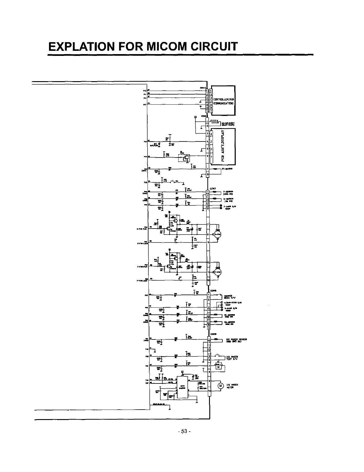
EXPLATION FOR MICOM CIRCUIT
)
T
T_
=-. T=
v
.. . T=,.
E
_ mm
-53 -

CIRCUIT
THE CIRCUIT DRAWINGS
CIRCUIT DIAGRAM
MODEL : GR-D267**U
-I.!O_ e_/tpA_IW&_ FrcA_R,DOOFI_N_,CA=_.JT0_pAIT_,PI.UGWI=E,C_FIFJ_ E_qrtHpAR'_,
Ft.OTV_._EONQ;_C_IITDIA_qAt_&qESl_MEC'TTOCf,IiV_EIND_RIE_T _/_O ACCORDANQE_M0_I_ 'i'YPF_
*N:HBrf_qL PWB._SEMBLY,MAIN
m_
PWBASSEMBLY,DISPLAY
SUBCONTROLLER
BK : _._'( M :BROW_ BO :BRIOpITOf_,_IE QY :E_Y RD: RED
Yr. : YELI.OW 13N : _qEEN PR : PUI=P.JE WH : wHr_ Wt'b_K : _
_B ;_O'I_UE P'_ :PINK GN/W_ :61R_/yLqJJ_W BlaW_:BI.UF2_ITE FIB/VAH:RE_Nt,.41TE
3854JD1076B
-54-
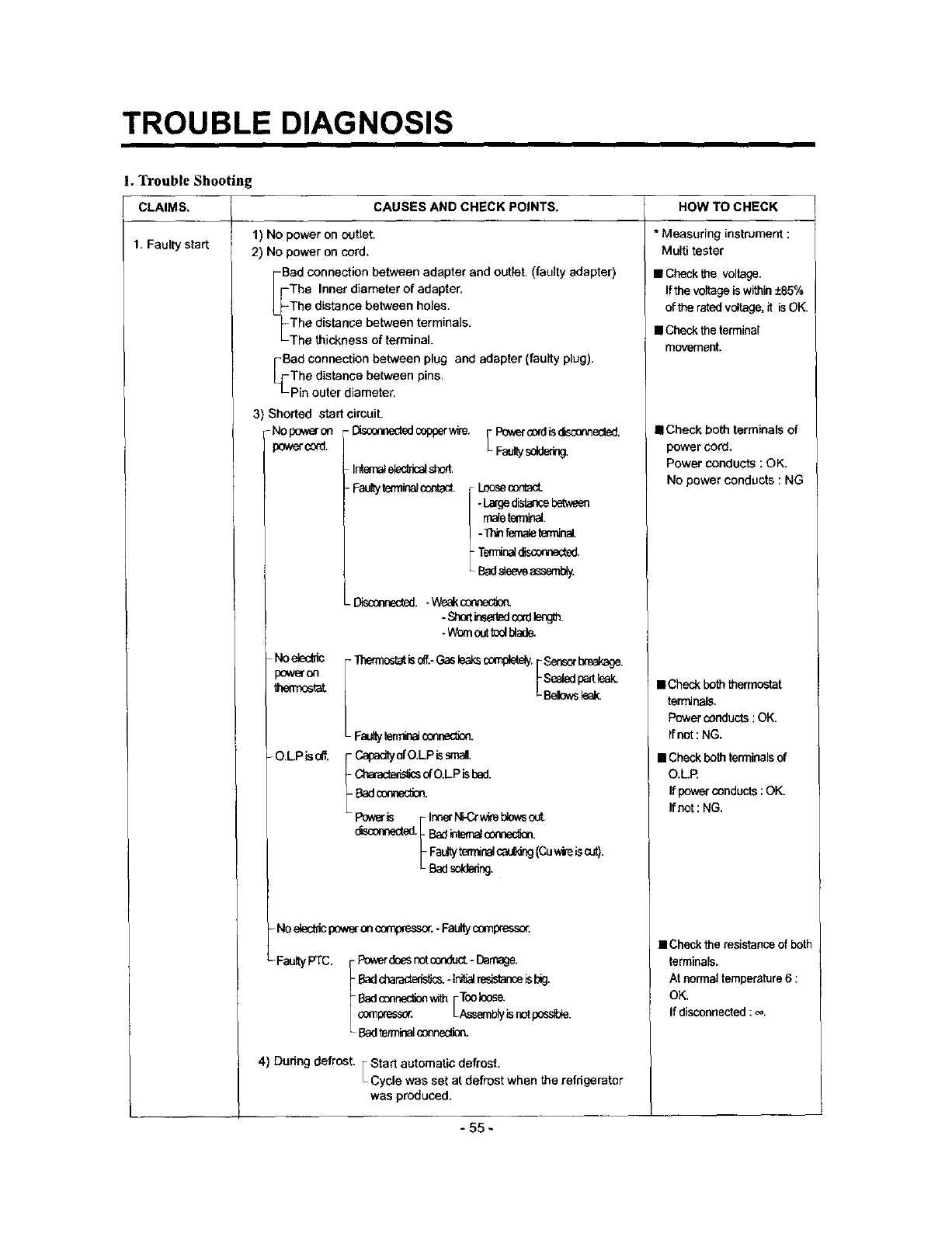
TROUBLE DIAGNOSIS
1.3¥ouble Shooting
CAUSES AND CHECK POINTS. HOW TO CHECKCLAIMS.
1. Faulty start 1) No power on outlet.
2) No power on cord.
Bad connection between adapter and outlet. (faulty adapter)
The Inner diameter of adapter.
The distance between holes.
The distanse between terminals.
The thickness of terminal.
Bad connection between plug and adapter (faulty plug).
The distance between pins,
Pie outer diameter,
3) Shorted start circuit.
Nopeweron -Disconnededcopperwire. [Pr_c_dgolsca'm_.
_wer_:_. _ Fa_ys_
INemal_Ncat sh_,
-Faulty terminalcontact, [Loosecont_t.
/ -La_d_,_r_ebe_v_
[malete_ninal.
_ -Thin_role _rrr_nal.
Temlir_ olscer_ected.
L Badslseveasseml_y
._.. Weak connec_
-Short_sat_dc0at_mgth.
- Wornout t_l btade.
- Noe_c_ic
)ower co
thennoatat
- O.L.PIS oil,
I Sensorbreakage.
_tat is _.- Gas _aks completely.FSealedpartleak.
L Bellowsleak.
L FI_llty [e_ COt_(_Otl.
f Capadty of O.LP issinai,
Characte_s_sofO.LP ls13ed.
Badconne_on.
Po_ F InnertCCr wi_eblowsout
_Fa_'tyterminalcau_,ing(Cuwireiscut).
L Bad soldering,
-NO electncpower on c_%o_.ssor.-Faultycompresso_
-FaultyPTC. Powerdoesnct(z_c_ - Damage.
-Badcharact_si_.-Ini_ reslstan_isbig.
Badcennec_nwith[Tco Ioos_
compressor. Assemblyisnctpossble.
Badterminal_.
4) During defrost. FStart automaticdefrost.
LCycle was set at defrost when the refrigerator
was produced,
* Measuring instrument :
Multi tester
• Checkthe voltage.
Ifthevoitageis within+85%
ofthe ratedvoltage,it isOK.
• Checktheterminal
movement.
• Check both terminals of
power cord.
Power conducts :OK.
No power conducts : NG
• Checkboththermostat
terminals.
Powerconducts:OK.
If not:NG.
• Check both terminals of
O.L.R
If power conducts ; OK,
ffnot: NG.
•Check the resistance of both
terminals.
At normal temperature6:
OK.
If disconnected : _.
- 55 -
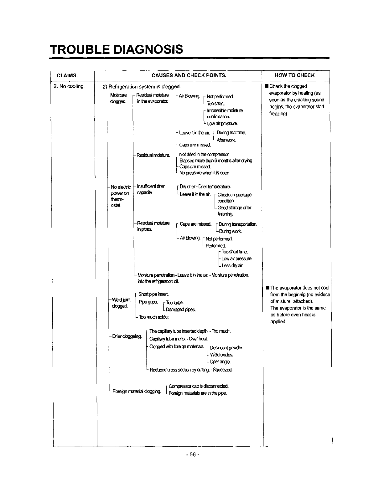
TROUBLE DIAGNOSIS
CLAIMS. CAUSES AND CHECK POINTS. HOW TO CHECK
2, No cooling, 2) Refrigeration system is clogged.
Moisture - Residualrn_ AirBIowing.
dogged, in_ evamra_r.
-Residualrndsture.
Noelec_c In_ d_r
powe"on capadty
tbean-
ostat.
-Residualrnoisture
_npipes,
i Notperforated.
TooshorL
Impo_UereoL_re
- Leaveitinlf_eair. _ Duringrest _ne,
LNterwork.
Capsaremissed.
[ Notdr_din_heoompr_.
Elapsedmore_a_ 6monthsa_erct'ying
Capsaremissed.
No pressurewheniUs open.
i o_yd_er- mettempera_ue.
i¢_._dsilagea_
Capsare missed. _ DudngfTa_0o_
LA_ing_k.
T_sh_n&
I.x_ _ _ssure.
Less d_/a_
Wedjo_ f'St_t P_e"_
dogged. Pipeg_os. Toolarge.
[_aged rues.
L TOOrnuchsdde_
- Dnerdoggeing. I Thesapillay tubeinserleddepth.- Toomud_.
_ M_ mere,-c_r heat
c_gedw_foragnrnater_,__Descantpo*d_.
Wetdoxides.
LI:Xieran_e
Reducedc_osssec_onbycut_ng.._eezed,
FO:_cap _sd_.
Foreignrnatedalck)gging.LFofe_j_n_tedalsa_einthepipe.
• Check the dogged
evaporator by heating (as
soon as t_e crack,Jngsound
begins, I_e evspora_r start
freezing)
• The evaporator does not coo
from the beginnig (no evidece
of mislure attached).
The evaporator is the same
as before evenheat is
applied.
- 56 -
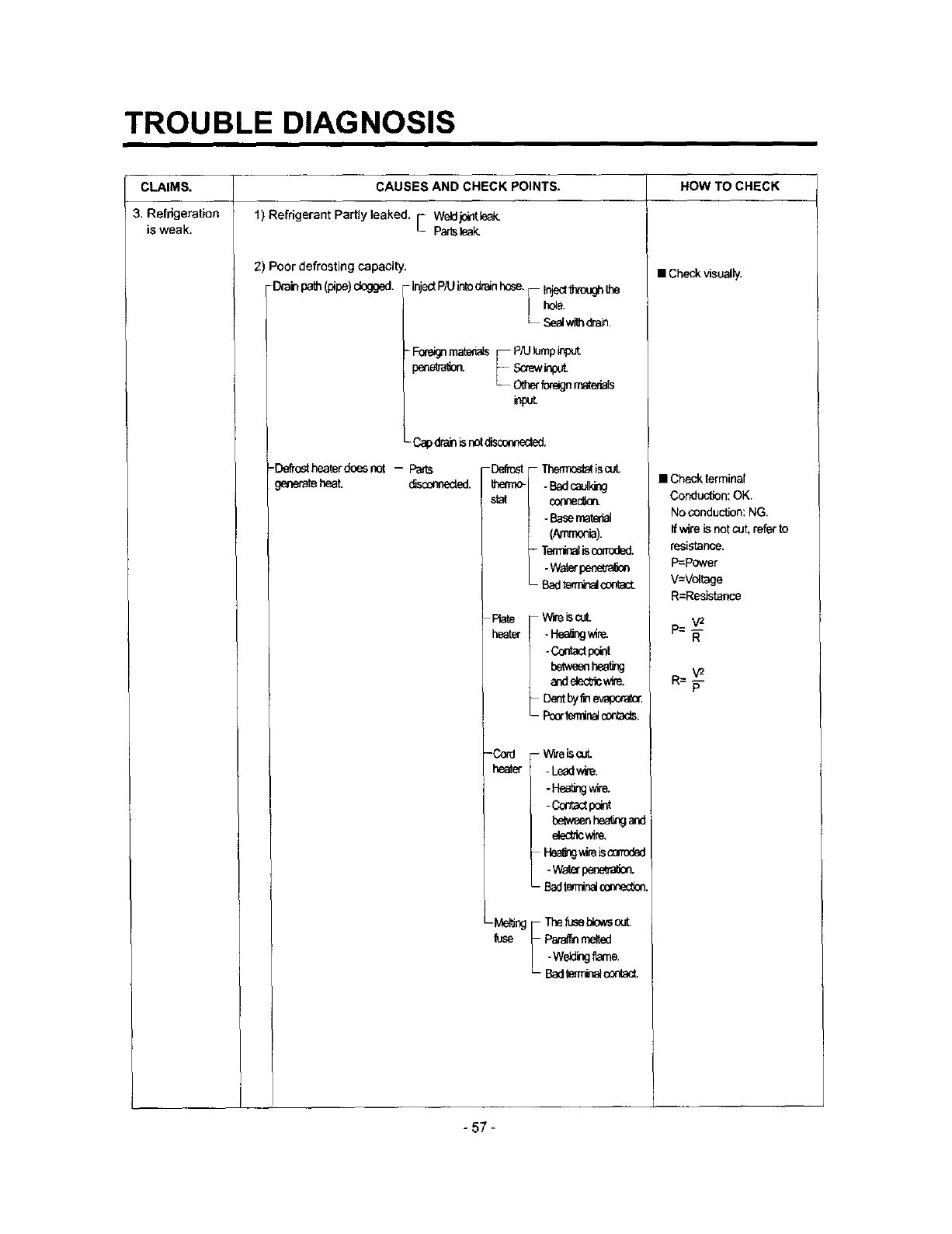
TROUBLE DIAGNOSIS
CLAIMS.
3. Refrigeration
is weak.
CAUSES AND CHECK POINTS.
1) Refrigerant Partly leaked. FWeld.k:_tle_
Lparisleak
2) Poor defrosting capacity.
-Draln path(pipe) dogged. -InjectP/U,_todrainhose._ Inject_:)u_the
h_e.
L _wJth droin,
-ForeignmaterialsF P_J_mp_reut
peae_a_o_ S_ewAo_
_ O_er_egnraa_mab
- Capdrainis notdisc_'_cted.
-Defrostheaterdoesnot -- Pa_
generateheal _nneded. -__ TherrnostatiscuL
-Badcalking
star connec_en.
- Basernatenal
-T_ _scomx_d.
-w_efpene_on
- Badts,_nim&cx_f_caK:t
I_te I W_iscut.
heater -Hea_ngwire.
-Cor_act_t
_tweenhe,_
a_e_cw_
Dentby_nevapo'a_
- I:_r t_ninal cmtacts.
- heatCh_tder- WireiscuL
-Le_lwire.
-Hea_J_e.
-Cmtactmint
I:L-_weenhe.rigand
elecl_ wire.
Hea_w_e_scorroded
.w_erpe.er_.
-Badtwmi_ connec_L
•Me_ng F Thefusel:_&
fuse _ Para_ melted
_- Badterrrinalcontact.
HOW TO CHECK
• Checkvisually.
• Check terminal
Conduction: OK.
No conduction: NG.
If wire is not cut, referto
resistance.
P=power
V=Vol_age
R=Resistance
p=___
R
R=w
P
- 57 -
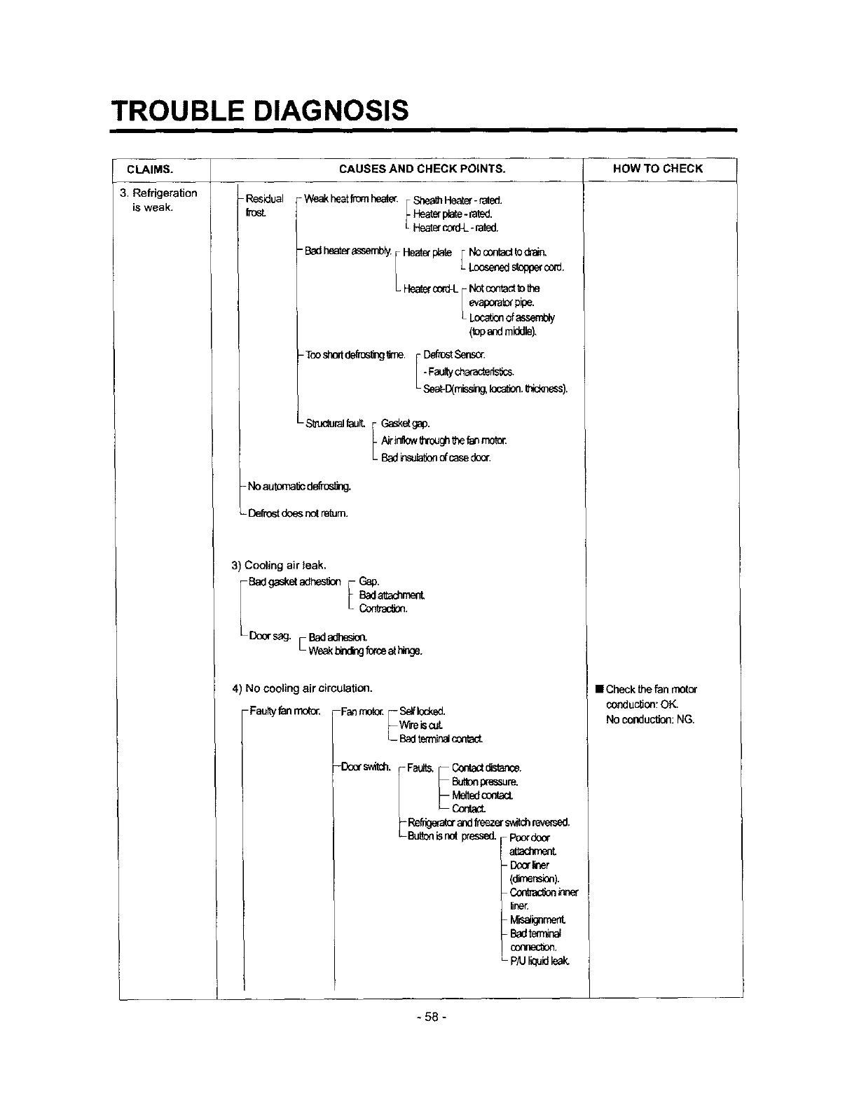
TROUBLE DIAGNOSIS
CLAIMS.
3. Refrigeration
is weak.
CAUSES AND CHECK POINTS. HOW TO CHECK
Residual
fresl - WeakheatfmrnhesS, F_ Heater_rated'
_-Heaterplate-rated.
L Hest_cord4_-rated.
-B_ heata'asserr_y.
He_p_te [Nocontadtodrain,
Loesenedstop_c_d.
(topendmiddle).
Def_Senson
-Tonshorldefros_g_me. i. Faun/d_arac_eris_cs,
• Sest-D(misdng,IocalJon._ess).
-S_c_& [ Ga_etgap.
L Air_llow6_rough_e fa_moto_
Badinsula_onofcasedes_
-Noautorua_cdef_os_g.
-Deftestdoes n_ ream.
3) Cooling air leak.
_Door sag Bad adhesion "
•
4) No coolingaircirculation,
-Faultyfanmotor. Fanmotor.F Selflocked.
_Wirei_c_
LBadtem¢_c_tact.
-Do_"swirl.
iCor_ct distance.
Fau_ _Butlonpressure,
!- Me_dc_a.
L- Contact.
_Refrigeratorandf_eze¢ switchreversed.
Buttonisnot pressed. Poordocr
attar
- Doorliner
(d_ner_n).
C_ _ner
line_
- M6alignment
- Badterr_
connection.
P/U I_id le_
• Check the fan motor
conduction: OK,
No conduction:NG.
-58 -
TROUBLE DIAGNOSIS
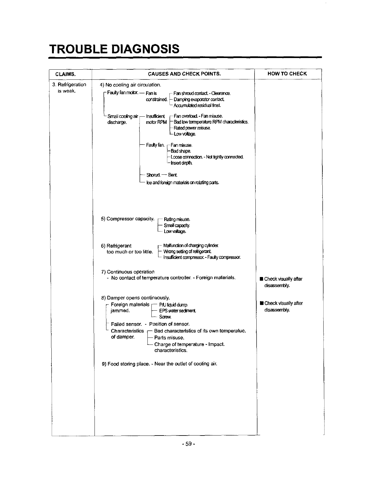
CLAIMS.
3. Refrigeration
is weak.
CAUSES AND CHECK POINTS.
4) No cooling air circulation.
[ Faultyfan rnotor.-- Fanis F FanshroxJc_ -Cisarance.
cons'_ained._ D_ e_ c_d_ct.
_-Accumulatodresidualfm_t
L Smallceding air Ins_cier_ F Fa_ovedasd.- Fas mLsuse,
disd'_rge, motorRPM I- BadlowtermperatureRPMdnara_eris_s.
L Rated ix_,_ m_use.
-- Faultyfan, F Fanmisuse.
_-Lseseoo_eO_.-N__Uysen,,_.
'- Insertdei_h.
-- ShonJd.-- Bent.
Iceand fcxe_nmate_ on rota6_ pats,
5) Compressor capacity, • I_ng misuse.
i- srseucapa_
L LOwvaltage.
6) Refrigerant F M_of_cylnde_
too much or too little, [- Wn0ngset_gc#refrk_L
L ]nsul_t c0mprass_ *Faultycom_
7) Continuous operation
- No contact of temperature controller. - Foreign materials.
8) Damper opens continuously.
iForeign materials F P/U liqukl_Jmp.
jammed. _EPSscmwWa_sediment.
Failed sensor. - position of sensor,
Characteristics F Bed cheracteds_cs of its own temperatee.
of damper. _ Parts misuse.
LCharge of temperature - Impact.
characteristics.
9) Food storing place, - Near the outlet of cooling air,
HOW TO CHECK
• Check visually after
disassembly.
• Check visuallyafter
disassembly.
- 59 -
TROUBLE DIAGNOSIS
i i
HOW TO CHECK
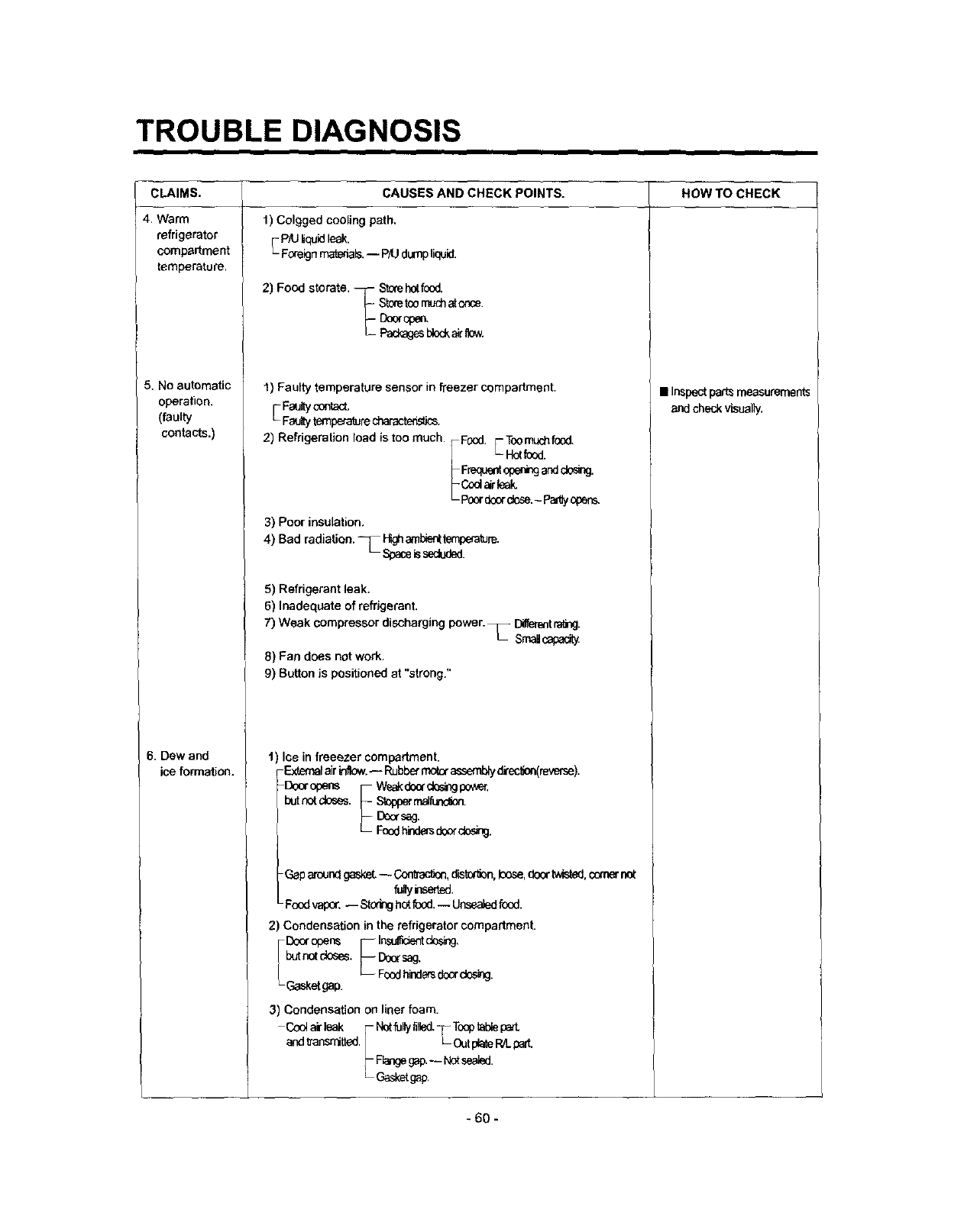
CLAIMS.
4. Warm
refrigerator
compartment
temperature.
5. No automatic
operation.
(faulty
contacts.)
6. Dew and
iceformation.
CAUSES AND CHECK POINTS.
1) Colgged cooling path,
FPIU Nqu_dleak.
Foreignma'_a_.I pM dump liquid.
2) Food storate. --7 Storehotf_:x)d.
_- St_e too rT_chatonce.
1) Faulty temperature sensor in freezer compartment.
E Faultycontact,
Faultytemperaturecharactedst_.
2) Refdgeration load is too much.
3) Poor insulation.
Food. F Toomuchfood.
_-Hotfood,
Fr_,J_ oper,__nddose.
Cod _leak
Poor doordose.- Padlyopens.
4) Bad radiation. T Pr_,ha'nbienttemperature.
L Spaceissecluded.
5) Refrigerant leak.
6) Inadequate of refdgerant.
7) Weak compressor discharging power. _ Dilfemntra_rlg.
Srnalc_padty
8) Fan does not work.
9) Button is positioned at "strong."
lee in freeezer compartment.
-External air irfflow.-- Rubber motor assembly direc_on(mverse).
-Do.opens r- w_.._n_e_
-Gaparaundgasket-- C,onlra_, dis_of_on,loose,doortwisted,cornernct
f_y inserted.
Food_, -- St0d_h_ f_d. -- Unsea}edfood.
2) Condensation in the refrigerator compartment.
FI:_ opens F Im,.,_entdo,_,
_ Foodhindemdo__b_ing.
butn_ doses. I_'sag.
Gasketgap.
3) Condensation on liner foam.
Co_ air leak [- Notfullytilk_d._- T_p tablepart
and _ansrritted. l_ OutplatePaLparC
_Gask_gap.
• Inspect pad_ measuremerf_s
and check visually.
- 60 -

TROUBLE DIAGNOSIS
CLAIMS.
6. Dew and
ice formation.
7. Sounds
CAUSES AND CHECK POINTS. HOW TO CHECK
4) Dew on door.
_-- Dew on the duct door. - Duct door heater is cut.
-- Dew on the dispanse FRecessHeaterisojt
recess. LDuctdoods operl./Fore_g__ d_
-- Dew on the door surface. _ Not fully fiUed. T Surface._
LLCormer_ Liquidshl:tal3e'
P/U liquid contraction. _ Liq_l!eek
Dew on the --F Badwingadhesion. [W'_j sagOowerp_t ).
gasket surface. [ LDOerliner_ m_=mat_.
_-Comer.-- r- Toomuchr'mtc_,
]LBroken.
LHomeBar heateriscut.
5) Water on the floor.
-- Dew in the refrigerator compartment.
-- Defrosted water overflows. -- Clogged discharging hose.
-- Discharging hose -- Evaporation tray located at wrong place.
location.
-- Tray drip. _- Damaged.
I_ Breaks. holes.
L Small Capacity.
-- Position of drain.
) Compressor compartment operating sounds.
-- Compressor sound _- Sound from machine itself.
L Sound from vibration.
- Restrainer.
- Rubber]-- Tea hard.
seat. _ Distorted.
_- Aged.
_- Bumt.
Stopper.--Bad StopparTNot fit
assembly. _(inner
| diameter
of stopper).
_Tilted.
LNot inserted.
-- Compressor base not connected.
Bad welding compressor stand(fallen).
Foreign materials in the compressor
compartment.
--O.L.R sound. ----Chattering sound.
-- Capacitor noise. -- Insulation paper vibration.
-- Pipe sound. _ Pipe contacts each other. - Narrow interval.
No vibration damper. • Damping rubber-Q.
L Damping rubber-S,
-- Capillary tube unattached.
- 61 -

TROUBLE DIAGNOSIS
CLAIMS.
7. Sounds
CAUSES AND CHECK POINTS.
) Compressor compartment operating sounds.
Transformer sou nd. --_ Itsmvnfault.-- Coregap.
_Badcon_. -- _ screwconnection.
-- Drip tray vibration sound._ _ a_-=mbly.
i-E
-- Back cover machine sound, _ Badconnec_n.
LPal_,da_,aged.
-- Condenser drain sound. _ Notconnected.
L _d pipec_ng.
2) Freezer compartment sounds.
-- Fan motor sound. _- Nom'elopera_ngs_d.
V_Jonso_d.-- F- Agedrubberseat
L L_d _orqueforasserrb!ingrno_
brad<_
-- Sounds from fan - -Fangddeconta_
contact. _- Shroudburrconlact.
LNa_r_ _'atar ir_,,'aL
-- Unbalance fan sounds_ -- Unb_ar:ce.-]- Surfacemad-_ni'_jconditJcns,
i- Fan_tor_.
Ioeon_lef_, --/_r inl_e(_te torno_
-- Motor shaft _ Supporlerdisoded,
contact sounds. L Tiltedduringrnotorassem_
_-- Resonance.
Evaporator noise. _ Evaporatorpipecontact.-- Nod_ eva_
So,rodfromfinevapora_ and p_e dudnge,'q0ansion
and comac_n.
3) Bowls and bottles make contact on top shelf.
4) Refrigeratorroof contact.
5) Refrigerator side contact.
6) Insufficient Lubricants on door hinge.
HOW TO CHECK
- 62 -

TROUBLE DIAGNOSIS
CLAIMS.
8. Faulty lamp
(freezer and
refrigerator
compartment)
9. Faulty internal
voltage(short).
CAUSES AND CHECK POINTS.
1) Lamp problem. _-- Filament blows out.
L__ Glass is broken.
2) Bad lamp assembly. _Not inserted.
L---- Loosened by vibration,
3) Bad lamp socket.
-- Disconnection._ Bad soldering.
Bad rivet contact.
--Short. Water penetration:-- Low water
level in tray,
IBad elasticity of contact.
-- Bad contact(corrosion).
4) Door switch.-- -- Its own defect.
-- Refrigerator and freezer switch is reversed.
-- Travlel distance.
-- Bad connection.
-- Bad terminal contact.
-- P/U tlquid leak..
1) Lead wire is damaged.
- Wire damage when assembling P.T.C. Cover.
- Outlet burr in the bottom plate.
- Pressed by cord heater, lead wire, evaporator pipe.
2) Exposed terminal.
Compressor Compartment terminal - Touching other
components.
Freezer compartment terminal. - Touching evaporator pipe.
3) Faulty parts.
-- Transformer. _Coil contacts cover.
L__ Welded terminal parts contact cover.
-- Compressor. -- Bad coil insulation.
-- Plate heater.
-- Melting fuse. --Sealing is broken.- Moisture penetration.
- Cord heater. _-Pipedamaged.--Moisturepenetration.
_- Bad sealing.
i
i _ Sheath heater.
HOW TO CHECK
•Connect conduction and
non-conductionparis and
checkwith tester.
Conduction: NG.
Resistances: OK.
- 63 -
TROUBLE DIAGNOSIS
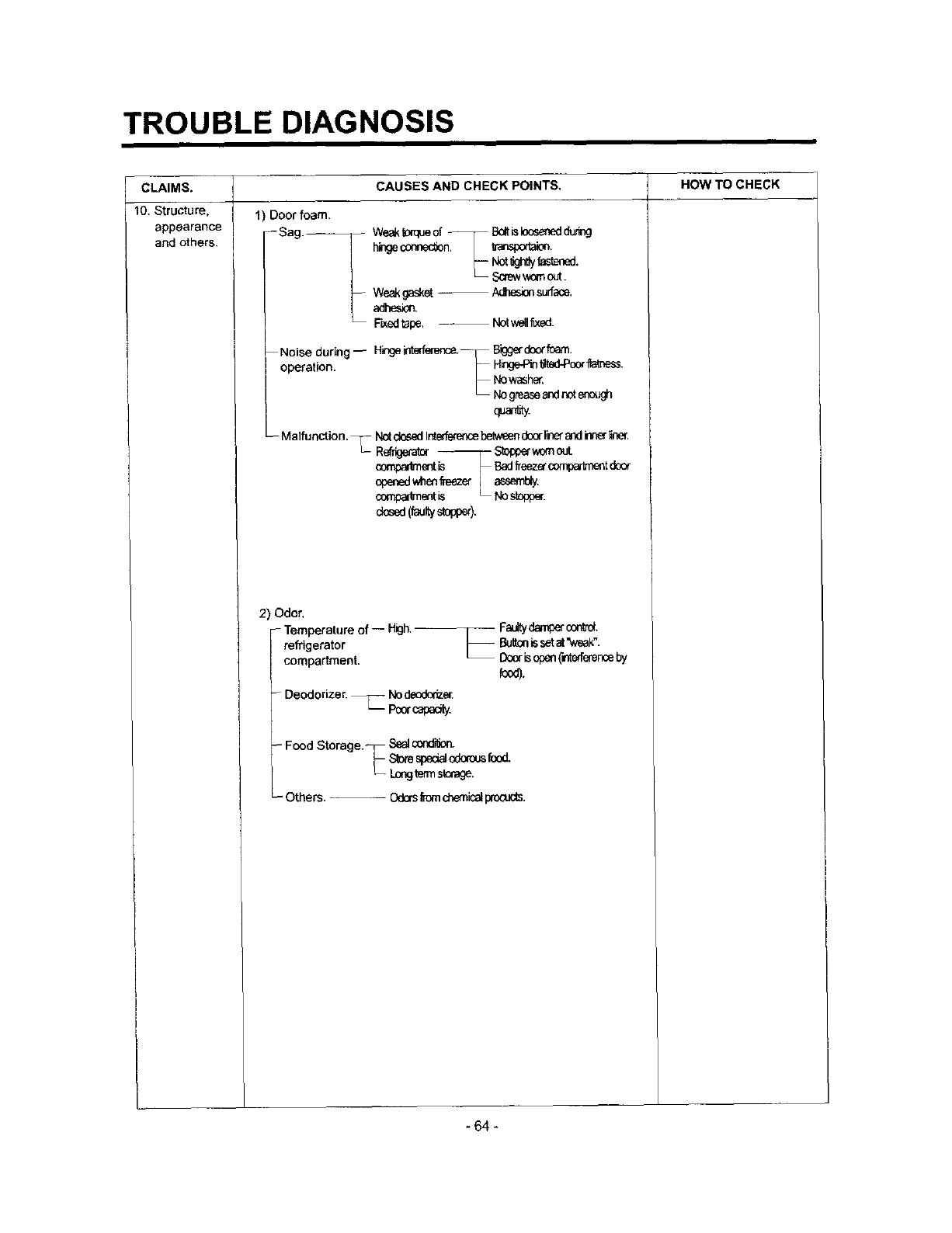
CLAIMS.
10. Structure.
appearance
and others.
CAUSES AND CHECK POINTS,
1) Door foam.
Sag _
-- Noise during --
operation.
-- Malfunction.
Weakt0mueof _ B_t isIoQsenedd,J,,ing
hingeconne(_n. _nsl:,:_aim.
_ Sony v,_rnout.
Weak gasket -- Acliesion surf_e.
adhesion.
Fked tape. -- Not wel_xed.
H_ge interference._ Biggardoorfoam
VNo_sher.
_ No gm.m_eandnetenough
q_n_y.
N_ dosedletefferer'_cebetweendoerliner_d inner,Ir_
Reffigeret_ T-S_opp_w_nouL
compa_nt k _ E_ _eez_ comet do_
openedwhmf_zer _s_
compartment_ .
dosed(_y stopp_).
2) Odor,
- Temperature of -- High.--_ Faultydampercon_'d+
refrigerator I_ Buttonissetet%_eak".
compartment. _ _ isopen(interferer:c,eby
food).
-Deodorizer._ Node_dz_.
Po_capa_.
-- Food Storage._ Sealc_ldi_on.
_-s_s_o_o_
L--Longterrns_rage,
-- Others. OdorsfromchemicalprooJcts.
HOW TO CHECK
- 64 -
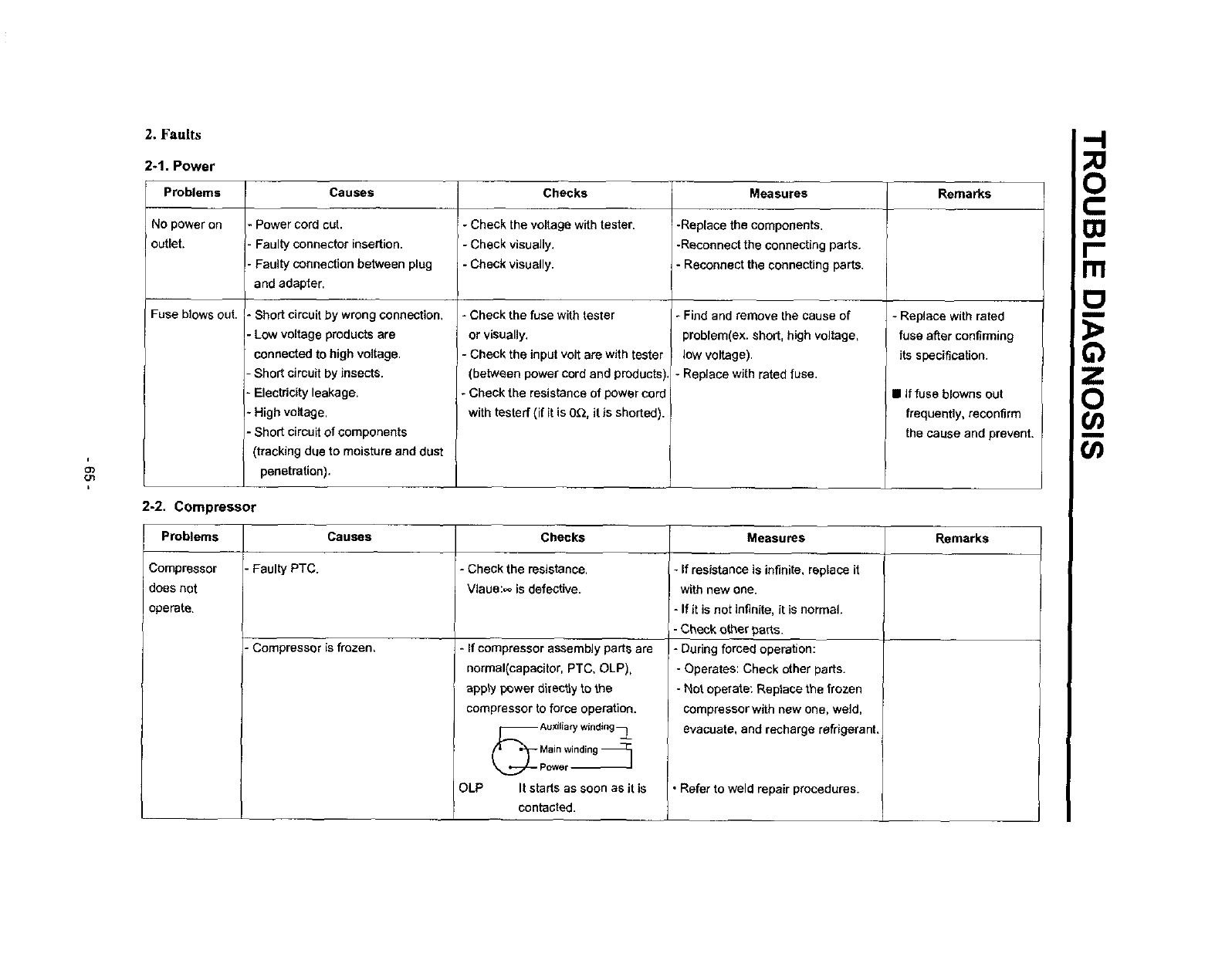
2. Faults
2-1. Power
Problems Causes Checks IMeasures Remarks
No power on •Power cord cut. - Check the voltage with tester• r-Replece the components.
i
outlet, - Faulty connector insertion. - Check visually. -Reconnect the connecting parts.
•Faulty connection between plug - Check visually. - Reconnect the connectJng parts.
and adapter.
Fuse blows out. • Short circuit by wrong connection,
- Low voltage products are
connected to high voltage.
•Short circuit by insects.
-Electricity leakage.
- High voltage,
- Short circuit of components
(tracking doe to moisture and dust
penetration).
- Check the fuse with tester
or visually.
-Check the input volt are with tester
(between power cord and products
-Check the resistance of power core
with testerf (if it is 0_, it is shorted).
-Find and remove the cause of
problem(ex, short, high voltage,
low voltage).
- Replace with rated fuse.
2-2. Compressor
Problems
Compressor - Faulty PTC.
does not
operate.
- Replace with rated
fuse after confirming
its spaclficaUon.
•If fuse blowns out
frequently, reconfirm
the cause and prevent.
Causes Measures RemarksChecks
-Check the resistance.
Vlaue:,,o is defective,
-If resistance is infinite, replace it
with new one.
- If it is not infinite, it is normal•
-Check other parts.
-During forced operation:
- Operates: Check other parts.
- Not operate: Replace the frozen
compressor with new one, weld,
evacuate, and recharge refrigerant,
Refer to weld repair procedures.
-Compressor is frozen, *If compressor assembly parts are
normal(capacitor, PTC, OLP),
apply power directly to the
compressor to force operation.
(_ Auxiliarywinding__
pM_ne:inding_
OLP It starts as soon as it is
contacted.
-I
?.
r-
m
_o
03
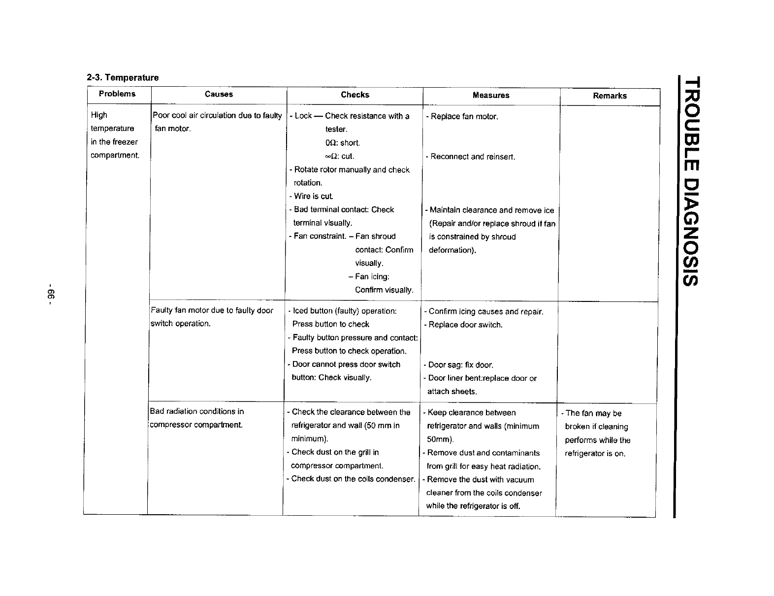
2-3. Temperature
Problems Causes Checks Remarks
High
temperature
inthe freezer
compartment.
Poor coolair circulation due to faulty
fan motor.
Faulty fan motor due to faulty door
switch operation.
Bad radiation conditions in
compressor compartment.
-Lock -- Check resistance w_tha
tester.
OQ: short.
_2: cut.
Rotate rotor manua,y and check
rotation.
- Wire is cut.
-Bad terminal contact: Check
terminal visually.
- Fan constraint. - Pan shroud
contact: Confirm
visually.
- Fan icing:
Confirm visually.
-Iced button (faulty) operation:
Press button to check
- Faulty button pressure and contact:
Press button to check operation.
*Door cannot press door switch
button: Check visually.
Check the clearance between the
refrigerator and wall (50 mm in
minimum).
- Check dust on the grill in
compressor compartment.
- Check dust on the coils condenser.
Measures
-Replace fan motor,
Reconnect and reinsert,
- Maintain clearance and remove ice
(Repair and/or replace shroud if fan
is constrained by shroud
deformation).
-Confirm icing causes and repair.
- Replace door switch.
-Door sag: fix door.
-Door liner bent:replace door or
attach sheets.
Keep clearance between
refrigerator and walls (minimum
50mm).
- Remove dust and contaminants
from grill for easy heat radiation.
- Remove the dust with vacuum
cleaner from the coils condenser
while the refrigerator is off.
- The fan may be
broken if cleaning
performs while the
refrigerator is on.
o
rtl

2-4. Cooling ""1
Problems Checks
F
O_
-.j
High
temperature
in the freezer
compartment.
Causes
Refrigerant leak.
Shortage of refrigerant.
Check sequence
1. Check the welded parts of the
drier inlet and outlet and drier
auxiJialy in the Compressor
compartment (high pressure side).
2. Check the end of compressor
sealing pipe (low pressure side).
3. Check silver soldered parts.
(Cu + Fe /Fe + Fe).
4. Check bending area of wira
condenser pipe in compressor
compartment (cracks can
happen during bending).
5. Check other parts (compressor
compartment and evaporators in
freezer compartment).
Check frost formation on the surface
of evaporator in the freezer
compartment.
- If the frost forms evenly on the
surface, it is OK.
- If it does not, it is not good.
Measures
Weld the leaking part, recharge the
refrigerant.
-Find out the leaking area, repair,
evacuate, and recharge the
refrigerant.
-No leaking, remove the remaining
refrigerant, and recharge new
refrigerant.
Remarks
Dder must be replaced,
Dder must be replaced.
i
Co
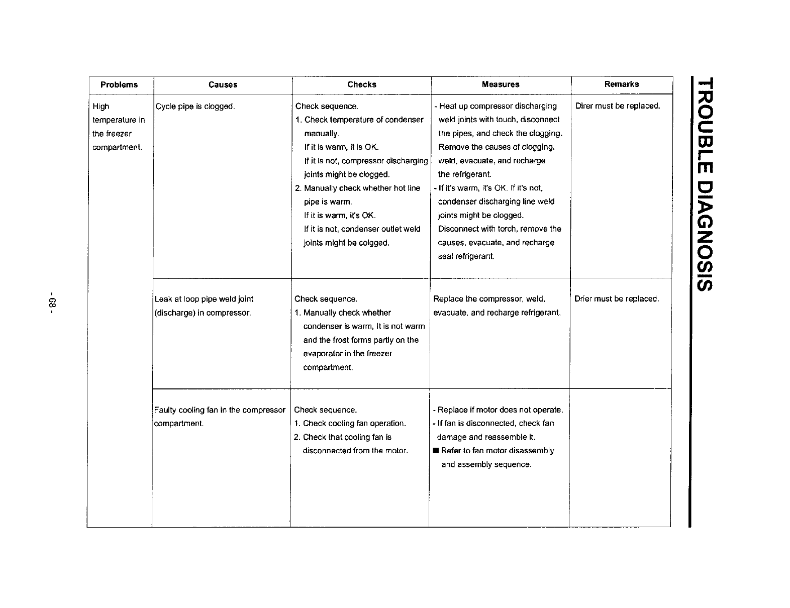
Problems Checks Measures
High
temperature in
the freezer
compartment.
Causes
Cycle pipe is clogged.
Leak at loop pipe weldjoint
(discharge) in compressor.
Faulty cooling fan in the compressor
compartment.
Check sequence.
1. Check temperature of condenser
manually.
If it is warm, it is OK.
If it is not, compressor discharging
joints might be clogged.
2. Manually check whether hot line
pipe is warm.
If it is warm, it's OK.
If it is not, condenser outlet weld
joints might be colgged,
Check sequence.
1. Manually check whether
condenser is warm, It is not warm
and the frost forms partly on the
evaporator in the freezer
compartment.
Check sequence.
1. Check cooling fan operation.
2. Check that cooling fan is
disconnected from the motor.
- Heat up compressor discharging
weld joints with touch, disconnect
the pipes, and check the clogging.
Remove the causes of clogging,
weld, evacuate, and recharge
the refrigerant.
- If it's warm, it's OK. If it's not.
condenser discharging line weld
joints might be clogged.
Disconnect with torch, remove the
causes, evacuate, and recharge
seal refrigerant.
Replace the compressor,weld,
evacuate, and recharge refrigerant,
-Replace if motor does not operate.
- If fan is disconnected, check fan
damage and reassemble it.
• Refer to fan motor disassembly
and assembly sequence.
Remarks
Direr must be replaced.
Drier must be replaced.
-I
m
_o
(/)
Or)
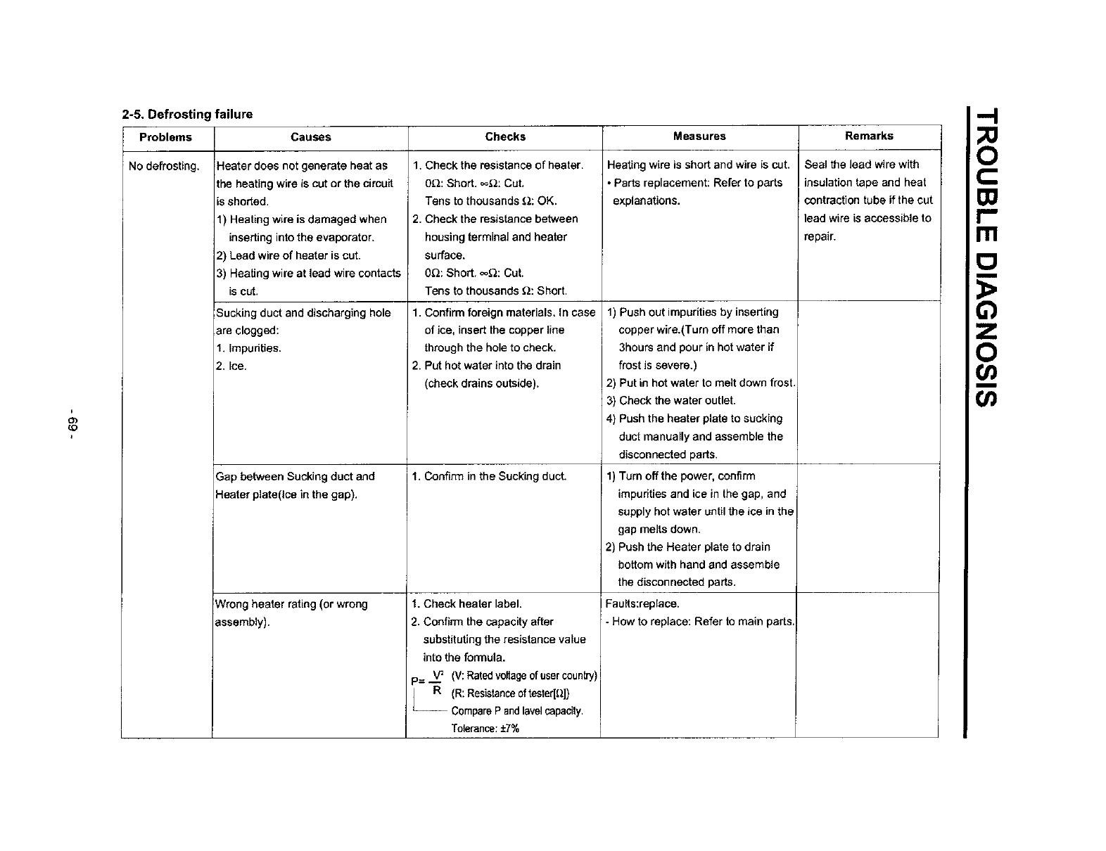
2-5. Defrostin failure
Problems Causes Checks Measures Remarks
&
(O
No defrosting. Heater does not generate heat as
the heating wire is cut or the circuit
=sshorted.
1) Heating wire is damaged when
inserting into the evaporator,
2) Lead wire of heater is cut.
3) Heating wire at lead wire contacts
is cut.
Sucking duct and discharging hole
are clogged:
1. Impurities.
2. Ice.
Gap between Sucking ductand
Heater plate(Ice inthe gap).
Wrong heater rating (or wrong
assembly).
1. Check the resistance of heater.
0_: Short. _2: Cut,
Tens to thousands _: OK,
2. Check the resistance between
housing terminal and heater
surface.
0Q: Short. _o_: Cut,
Tens to thousands Q: Short.
1. Confirm foreign materials, In case
of ice, insert the copper line
through the hole to check.
2. Put hot water into the drain
(check drains outside),
1. Confirm in the Sucking duct.
1. Check heater label.
2. Confirm the capacity after
substituting the resistance value
into the formula.
== ...__ (V:Rated voltage of user country)
R (R: Resistance oftester[_])
-- Compare P andlavel capacity.
Tolerance: ±7%
Heating wire is short and wire is cut.
• Parts replacement: Refer to parts
explanations.
1) Push out impurities by inserting
copper wire.(Turn off more than
3hours and pour in hot water if
frost is severe.)
2) Put in hot water to melt down frost.
3) Check the water outlet.
4) Push the heater plate to sucking
duct manually and assemble the
disconnected parts.
1) Turn off the power, confirm
impurities and ice in the gap, and
supply hot water until the ice in the
gap melts down.
2) Push the Heater plate to drain
bottom with hand and assemble
the disconnected parts.
Faults:replace.
- How to replace: Refer to main parts,
Seal the lead wire with
insulation tape and heal
! contraction tube if the cut
lead wire is accessible to
repair. F.
_o
o
O
Problems Causes Checks Measures Remarks
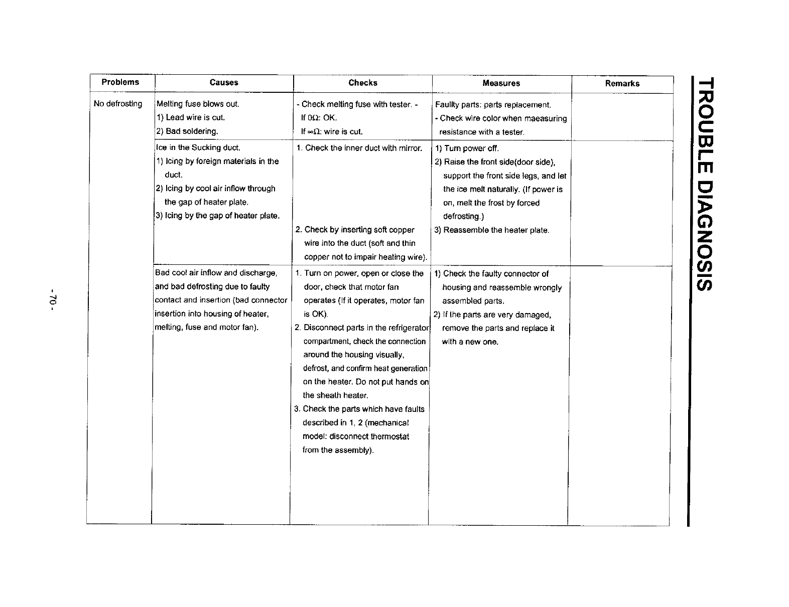
No defrosting Melting fuse blows out. - Check melting fuse with tester. - Faullty parts: parts replacement.
1) Lead wire is cut. If 0_2: OK. - Check wire color when maeasuring
2) Bad soldering. If ,_._: wire is cut. resistance with a tester.
Ice in the Sucking duct. 1. Check the inner duct with mirror. 1) Turn power off.
1) Icing by foreign materials in the
duct.
2) Icing by cool air inflow through
the gap of heater plate.
3) Icing by the gap of heater plate.
2) Raise the front side(door side),
support the front side legs, and let
the ice melt naturally. (If power is
on, melt the frost by forced
defrosting.)
Bad cool air inflow and discharge,
and bad defrosting due to faulty
:ontact and insertion (bad connector
insertion into housing of heater,
melting, fuse and motor fan).
2. Check by inserting soft copper
wire into the duct (soft and thin
copper not to impair heating wire).
1. Turn on power, open or close the
door, check that motor fan
operates (If it operates, motor fan
is OK).
2. Disconnect parts in the refdgerato_
compartment, check the connection
around the housing visually,
defrost, and confirm heat generation
on the heater. Do not put hands on
the sheath heater.
3. Check the parts which have faults
described in 1, 2 (mechanical
model: disconnect thermostat
from the assembly).
3) Reassemble the heater plate.
1) Check the faulty connector of
housing and reassemble wrongly
assembled parts.
2) If the parts are very damaged,
remove the parts and replace it
with a new one.
o
ITI
_o
(/)
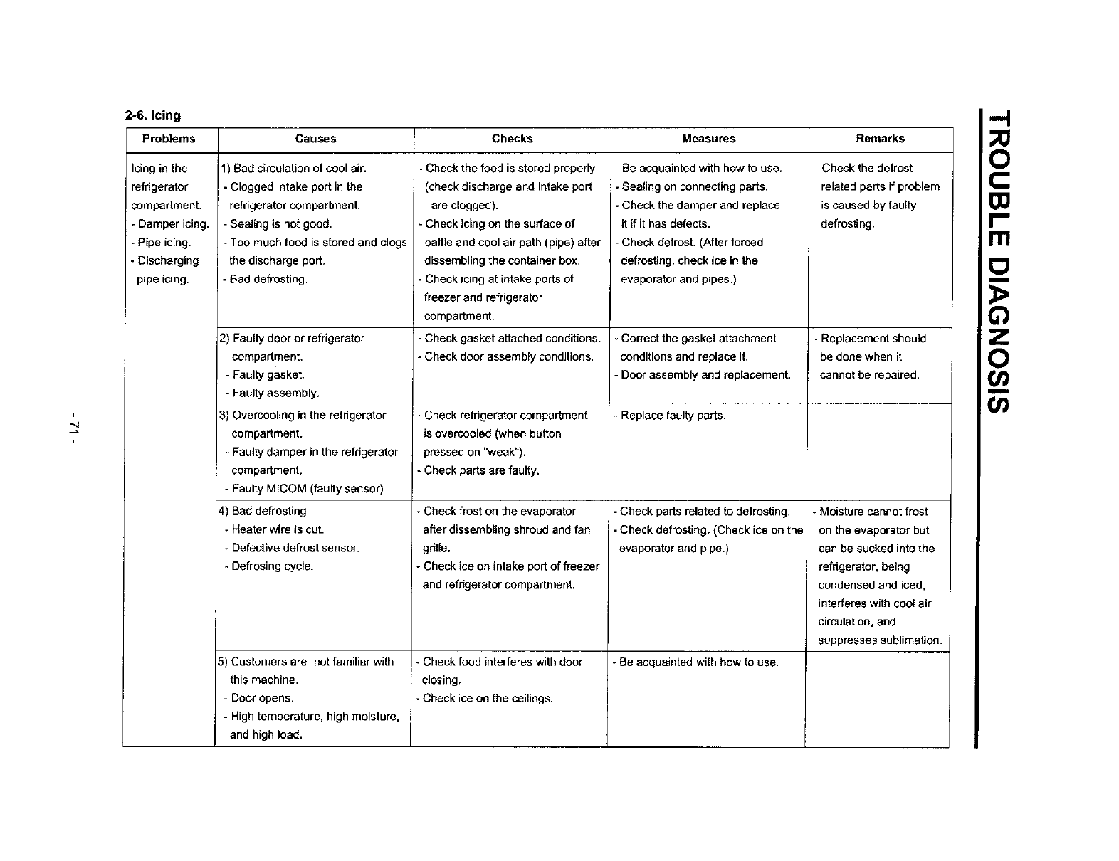
2-6. Icing
Problems Causes Checks Measures Remarks
i
Icing in the
refrigerator
compartment.
- Damper icing.
- Pipe icing.
- Discharging
pipe icing.
1) Bad circulation of cool air.
- Clogged intake port in the
refhgerator compartment.
- Sealing is not good.
- Too much food is stored and clogs
the discharge port.
-Bad defrosting.
2) Faulty door or refrigerator
compartment.
- Faulty gasket.
- Faulty assembly.
3) Overcooling in the refrigerator
compartment.
- Faulty damper in the refrigerator
compartment.
- Faulty MICOM (faulty sensor)
4) Bad defrosting
- Heater wire is cut.
- Defective defrost sensor.
- Defrosing cycle.
5) Customers are not familiar with
this machine.
- Door opens.
- High temperature, high moisture,
and high load.
- Check the food is stored properly
(check discharge and intake port
are clogged).
- Check icing on the surface of
baffle and cool air path (pipe) after
dissembling the container box.
- Check icing st intake ports of
freezer and refrigerator
compartment.
- Check gasket attached conditions.
- Check door assembly conditions.
-Check refrigerator compartment
is overcooled (when button
pressed on "weak").
- Check parts are faulty.
- Check frost on the evaporator
after dissembling shroud and fan
grille.
- Check ice on intake port of freezer
and refrigerator compartment.
- Check food interferes with door
closing.
- Check ice on the ceilings.
-Be acquainted with how to use.
- Sealing on connecting parts.
- Check the damper and replace
it if it has defects.
- Check defrost. (After forced
defrosting, check ice in the
evaporator and pipes.)
Correct the gasket attachment
conditions and replace it.
- Door assembly and replacement.
-Replace faulty parts.
- Check parts related to defrosting.
-Check defrosting. (Check ice on the
evaporator and pipe.)
- Be acquainted with how to use.
- Check the defrost
related parts if problem
is causedby faulty
defrosting.
-Replacement should
be done when it
cannot be repaired.
- Moisture cannot frost
on the evaporator but
can be sucked into the
refrigerator, being
condensed and iced,
interferes with cool air
circulation, and
suppresses sublimation.
rtl
o0
i
-.j
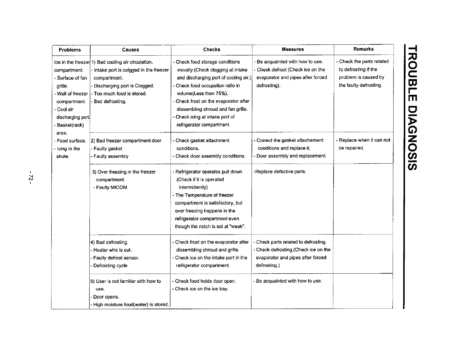
Problems
Ice in the freezer
compartment.
- Surface of fan
grille.
- Wall of freezer
compartment.
- Cool air
discharging port.
+ Basket(rack)
area,
- Food surface.
- Icing in the
shute.
Causes
1) Bad cooling air circulation,
-Intake port is colgged in the freezer i
compartment.
- Discharging port is Clogged.
- Too much food is stored,
-Bad defro_ing.
2) Bad freezer compartment door
• Faulty gasket
•Faulty assembly
3) Over freezing in the freezer
comparfment.
- FauI_MICOM.
4) Bad defrosting.
- Heater wire is cut.
- Faulty defrost sensor,
- Defrosting cycle
5) User is not familiar with how to
use,
-Door opens,
-High moisture food(water) is stored.
Checks
Check food storage conditions
visually.(Check clogging at intake
and discharging port of cooling air.',
- Check food occupation ratio in
volume(Less than 75%),
- Check frost on the evaporator after
dissembling shroud and fan grille.
- Check icing at intake port of
refrigerator compartment.
* Check gasket attachment
conditions.
- Check door assembly conditions.
-Refrigerator operates pull down.
(Check if it is operated
intermittently)
- The Temperature of freezer
compartment is satisfactory, but
over freezing happens in the
refrigerator compartment even
though the notch is set at "weak".
-Check frost on the evaporator after
dissembling shroud and grille.
- Check ice on the intake port in the
refrigerator compartment.
- Check food holdsdoor open.
- Check iceon the ice tray,
Measures
-Be acquainted with how to use,
- Check defrost (Check ice on the
evaporator and pipes after forced
defrosting).
- Correct the gasket attachement
conditions and replace it.
-Door assembly and replacement.
-Replace defective parts.
-Check parts related to defrosting.
- Check defrosting.(Check ice on the
evaporator and pipes after forced
defrosting.)
-Be acquainted with how to use.
Remarks
- Check the parts related
to defrosting if the
problem is caused by
the faulty defrosting.
-Replace when it can not
be repaired.
.-I
F.
_o
u)_
(/)
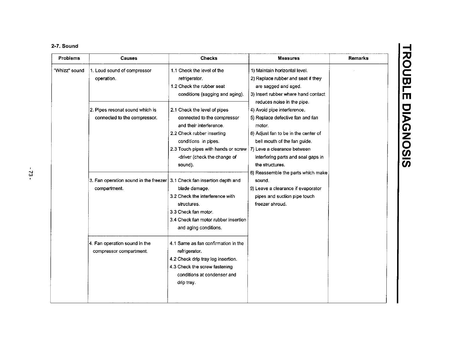
2-7. Sound
Problems
"Whizz." sound
Causes
1. Loud sound of compressor
operation.
2. Pipes resonat sound which is
connected to the compressor.
3. Fan operation sound in the freezer
compartment.
4. Fan operation sound in the
compressor compartment,
Checks Measures Remarks
1,1 Check the level of the
refrigerator.
1.2 Check the rubber seat
conditions (sagging and aging).
2,1 Check the level of pipes
connected to the compressor
and their interference.
2,2 Check rubber inserting
conditions in pipes.
2.3 Touch pipes with hands or screw
-driver (check the change of
sound).
3.1 Check fan insertion depth and
blade damage.
3.2 Check the interference with
slructures.
3.3 Check fan motor.
3.4 Check fan motor rubber insertion
and aging conditions.
4.1 Same as fan confirmation in the
refrigerator.
4.2 Check drip tray leg insertion.
4.3 Check the screw fastening
conditions at condenser and
drip tray.
1) Maintain horizontal level.
2) Replace rubber and seat if they
are sagged and aged.
3) Insert rubber where hand contact
reduces noise in the pipe.
4) Avoid pipe interference.
5) Replace defective fan and fan
motor.
6) Adjust fan to be in the center of
belt mouth of the fan guide.
7) Leve a clearance between
interfering parts and seal gaps in
the structures.
8) Reassemble the parts which make
sound.
9) Leave a clearance if evaporator
pipes and suction pipe touch
freezer shroud,
o
m
_o
i
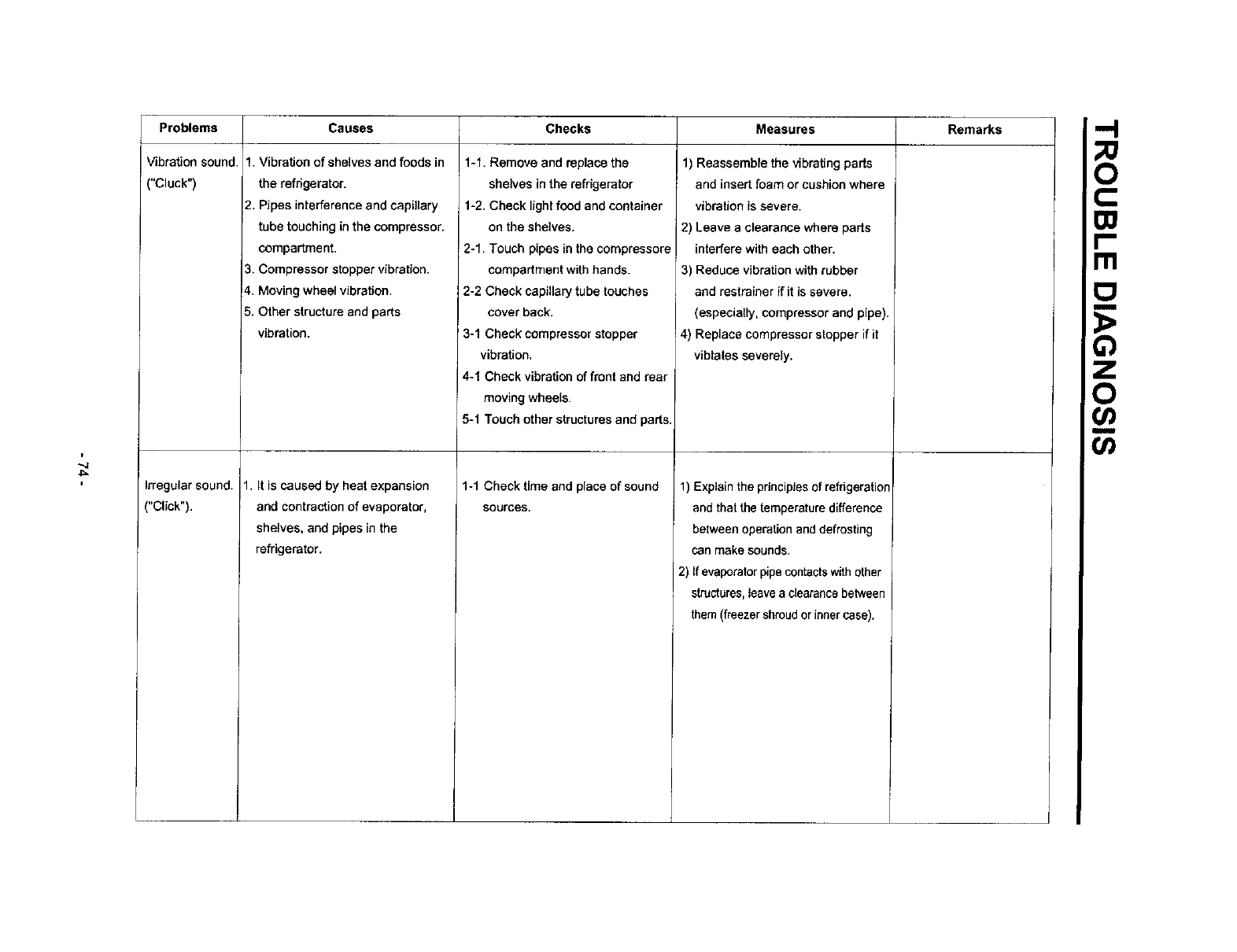
Problems
Vibration sound.
("Cluck")
Irregular sound.
("Click").
Causes Checks Measures Remarks
1-1. Remove and replace the
shelves in the refrigerator
1-2. Check tight food and container
on the shelves.
2-1. Touch pipes in the compressore
compartment with hands.
2-2 Check capillary tube touches
cover back.
' 3-1 Check compressor stopper
vibration,
4-1 Check vibration of front and rear
moving wheels.
5-1 Touch other structures and parts.
1. Vibration of shelves and foods in
the refrigerator.
2. Pipes interference and capillary
tube touching in the compressor.
compartment.
3. Compressor stopper vibration.
4. Moving wheel vibration.
5. Other structure and parts
vibration.
1. It is caused by heat expansion
and contraction of evaporator,
shelves, and pipes in the
refrigerator.
1-1 Check time and place of sound
sources.
1) Reassemble the vibrating parts
and insect foam or cushion where
vibration is severe.
2) Leave a clearance where parts
interfere with each other.
3) Reduce vibration with rubber
and restrainer ff it is severe.
(especially, compressor and pipe).
4) Replace compressor stopper if it
vibrates severely.
1) Explain the principles of refrigeratior
and that the temperature difference
between operation and defrosting
can make sounds.
2) If evaporator pipe contacts with other
structures, leave a clearance between
them (freezer shroud or inner case).
-I
Fn
_o
U)
i
".4
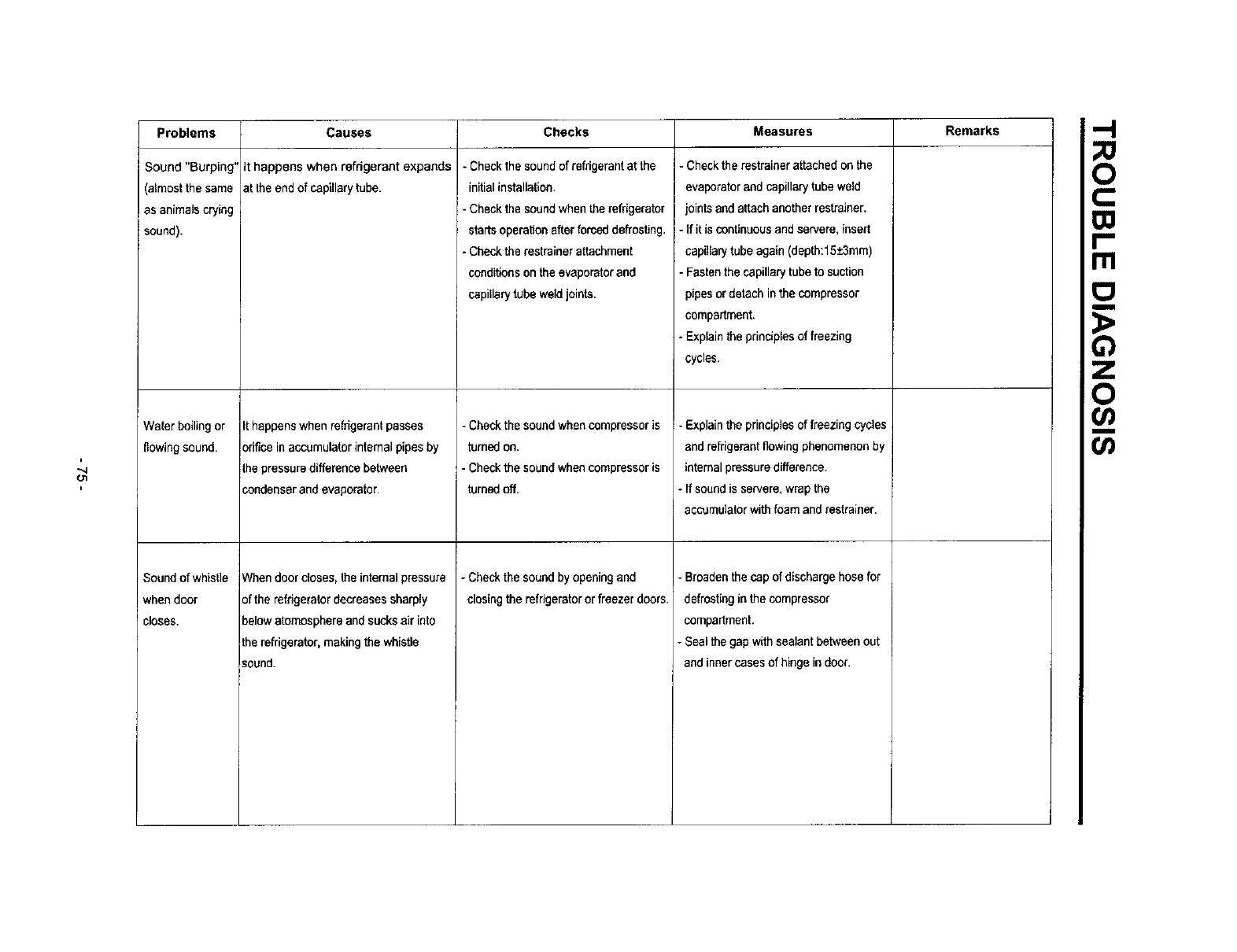
Problems Checks Measures Remarks
Sound "Burping"
(almost the same
as animals crying
sound).
Waterboilingor
flowingsound,
Sound of whisl]e
when door
closes.
Causes
It happens when refrigerant expands
at the end of capillarytube.
It happens when refrigerant passes
orifice in accumulator internal pipes by
the pressure difference between
condenser and evaporator.
When door closes, the internal pressure
of the refrigerator decreases sharply
below atomesphera and sucks air into
the refrigerator, making the whistle
sound.
- Check the sound of refrigerant at the
initial installation.
- Check the sound when the refrigerator
starts operation after forced defrosting.
- Checkthe restrainer attachment
conditions on the evaporator and
capillary tube weld joints.
- Check the sound when compressor is
turned on.
- Check the sound when compressor is
turned off.
- Checkthesoundbyopeningand
closingthe refrigeratororfreezerdoors,
- Check the restrainer attached on the
evaporator and capillary tube weld
joints and attach another restrainer.
- If it is continuous and servere, insert
capillarytube again (depth:lS±3mm)
- Fasten the capillary tube to suction
pipes or detach in the compressor
compartment,
- Explain the principles of freezing
cycles,
- Explain the principles of freezing cycles
and refrigerant flowing phenomenon by
internal pressure difference.
- If sound is servers, wrap the
accumulator with foam and restrainer.
- Broaden the cap of discharge hose for
defrosting in the compressor
compartment.
- Seal the gap with sealant between out
and inner cases of hinge in door.
,-I
Ill
_o
t,/}
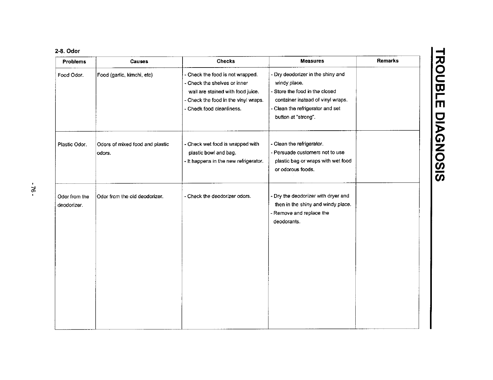
2-8. Odor ,_
Problems Checks Measures Remarks
i
O3
Food Odor.
Plastic Odor.
Odorfrom the
deododzer.
Causes
Food (garlic, kimchi, eto) J- Check the food is not wrapped.
-Check the shelves or inner
wall are stained with food juice.
- Check the food in the vinyl wraps.
- Chedk food cleanliness.
Odors of mixed food and plastic
3dors.
Ddor from the old deodorizer.
-Check wet food is wrapped with
plastic bowl and bag.
- It happens in the new refrigerator.
- Check the deodorizer odors.
- Dry deododzer in the shiny and
windy place.
- Store the food in the closed
container instead of vinyl wraps.
- Clean the refrigerator and set
button at "strong".
-Clean the refrigerator.
-Persuade customers not to use
plastic bag or wraps with wet food
or odorous foods.
- Dry the deodorizer with dryer and
then in the shiny and windy place.
-Remove and replace the
deodorants.
F.
_o
Or)
Or)
i
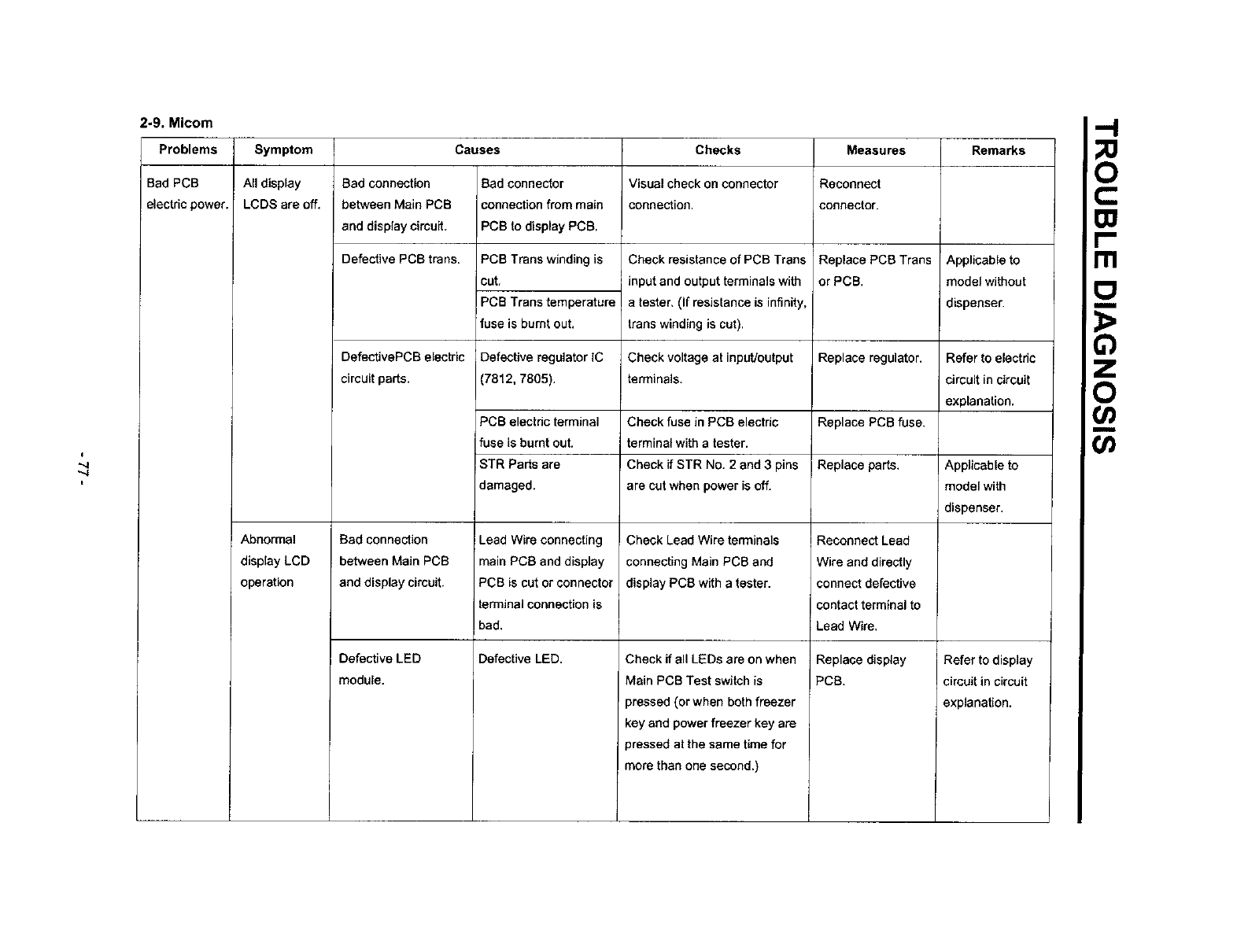
2-9. Micom
Problems
Bad PCB
electric power.
Symptom
All display
LCDS are off.
Abnormal
display LCD
operation
Causes
Bad connection
between Main PCB
and display circuit,
Defective PCB trans.
DefectivePCBelectric
circuit parts.
Bad connection
between Main PCB
and display circuit.
Defective LED
module.
Bad connector
connection from main
PCB to display PCB,
PCB Trans winding is
cut.
PCB Trans temperature
fuse is burnt out.
Defective regulator IC
7812, 7805).
PCB electric terminal
fuse is burnt out.
STR Partsare
damaged.
Lead Wire connecting
main PCS and display
PCB is cut or connector
terminal connection is
bad.
Defective LED.
Checks
Visual check on connector
connection.
Check resistance of PCB Trees
input and output terminals wifh
a tester, (If resistance is infinity,
trans winding is cut).
Check voltage at input/output
terminals.
Check fuse in PCB electdc
terminal with a tester.
Check if STR No. 2 and 3 pins
are cut when power is off.
Check Lead Wire terminals
connecting Main PCB and
display PCB with atester.
Check if all LEDs are on when
Main PCB Test switch is
pressed (or when both freezer
key and power freezer key are
pressed at the same time for
more than one second.)
Measures
Reconnect
connector.
Replace PCS Trans
or PCB.
Replace regulator.
Replace pCR fuse.
JReplace parts.
Reconnect Lead
Wire and directly
connect defective
contact terminal to
Lead Wire.
Replace display
PCB.
Remarks
Applicable to
model without
dispenser.
Refer to electric
circuit in circuit
explanation.
Applicable to
model with
dispenser.
Refer to display
circuit in circuit
explanation.
o
m
_o
i
Go
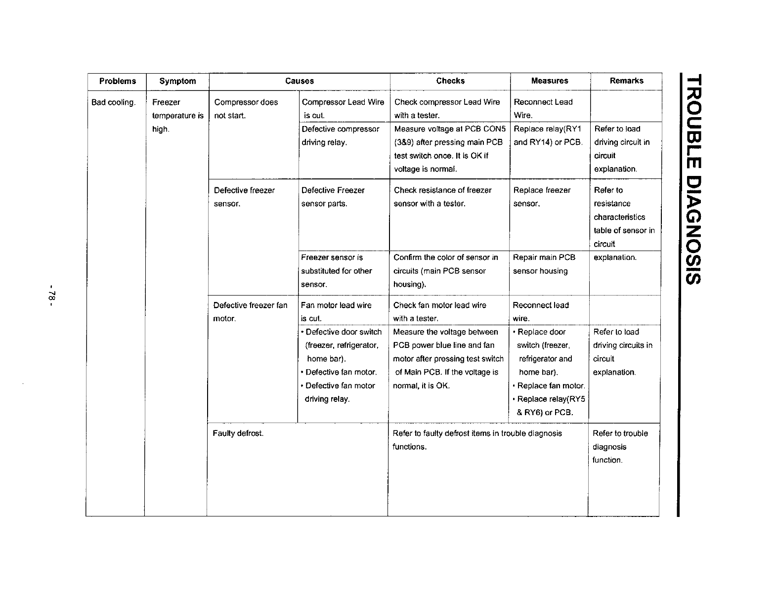
Problems
Bad cooling,
Symptom Causes Chocks Measures Remarks
Freezer
temperature is
high.
Compressor does
not start.
Compressor Lead Wire
is cut.
Defective compressor
driving relay.
Check compressor Lead Wire
with atester.
Measure voltage at PCB CON5
(3&9) after pressing main PCB
test switch once, It is OK if
voltage is normal.
Reconnect Lead
Wire.
Replace relay(RY1
and RY14) or PCB,
Refer to load
ddving circuit in
circuit
explanation.
Defective freezer Defective Freezer Check resistance of freezer Replace freezer Refer to
sensor, sensor parts, sensor with atester, sensor, resistance
charactedstics
table of sensor in
circuit
Freezer sensor is Confirm the color of sensor in Repair main PCB explanation.
substituted for other circuits (main PCB sensor sensor housing
sensor, housing),
Defective freezer fan
motor.
Check fan motor lead wire
with atester,
Measure the voltage between
PCB power blue line and fan
motor after pressing test switch
of Main PCB. If the voltage is
normal, it is OK.
Fan motor lead wire
is cut,
• Defective door switch
(freezer, refrigerator,
home bar).
• Defective fan motor.
• Defective fan motor
driving relay.
Reconnect lead
wire.
Replace door
switch (freezer,
refrigerator and
home bar).
• Replace fan motor.
•Replace relay(RY5
& RY6) or PCB.
Refer to faulty defrost items in trouble diagnosis
functions.
Faulty defrost.
Refer to load
ddving circuits in
circuit
explanation,
Refer to trouble
diagnosis
function.
F.
_o
0o
f
(D
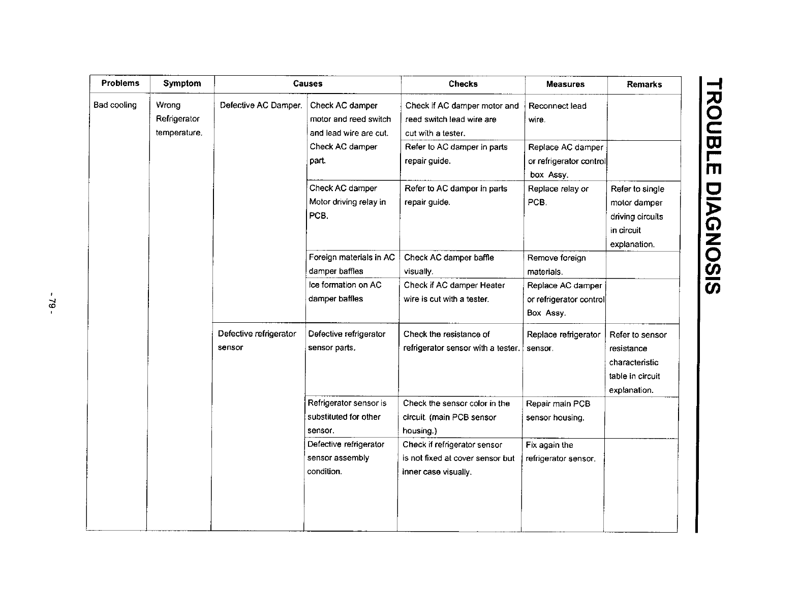
Problems
Bad cooling
Symptom Causes Checks Remarks
Wrong
Refrigerator
temperature.
Defective AC Damper.
Defective refrigerator
sensor
Check AC damper
motor and reed swffch
and lead wire are cut.
Check AC damper
part.
Check if AC damper motor and
reed switch lead wire are
cut with a tester.
Refer to AC damper in parts
repair guide.
Measures
Reconnect lead
wire.
Replace AC damper
or refrigerator control
box Assy.
Check AC damper Refer to AC damper in parts Replace relay or Refer to single
Motor driving relay in repair guide. PCB. motor damper
PCB. ddving circuits
in circuit
explanation.
Foreign materials in AC Check AC damper baffle
damper baffles visually.
Ice formation on AC Check if AC damper Heater
damper baffles wire is cut with atester.
Defective refrigerator
sensor parts.
Check the resistance of
refrigerator sensor with a tester.
Check the sensor color inthe
circuit. (main PCB sensor
housing.)
Check if refrigerator sensor
is not fixed at cover sensor but
Inner case visually,
Refrigerator sensor is
substituted for other
sensor,
Defective refrigerator
sensor assembly
condition.
Remove foreign
materials,
Replace AC damper
or refrigerator contr(
Box Assy.
Replace refrigerator
sensor.
Repair main PCB
sensor housing.
Fix again the
refrigerator sensor.
Refer to sensor
resistance
characteristic
table in circuit
explanation.
o
m
o>
(/)
O
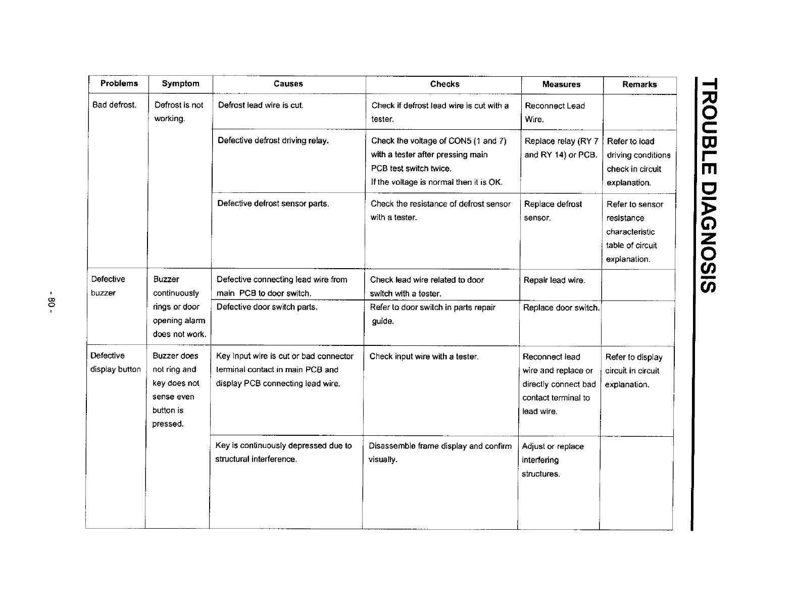
Problems Symptom Causes Checks Measures Remarks
Bad defrost. Defrost is not Defrost lead wire is cut. Check if defrost lead wire is cut with a Reconnect Lead
working, tester. Wire.
Defective defrost driving relay. Check the voltage of CON5 (1 and 7) Replace relay (RY 7 Refer to load
with a tester after pressing main and RY 14) or PCB. ddving conditions
PCB test switch twice, check in circuit
If the voltage is normal then it is OK, explanation.
Defective defrost sensor parts. Check the resistance of defrost sensor Replace defrost Refer to sensor
with a tester, sensor, resistance
charactedstic
table of circuit
explanation.
Defective Buzzer Defective connecting lead wire from Check lead wire related to door Repair lead wire.
buzzer continuously main PCB to door switch, switch with a tester.
dngs or door Defective door switch parts. Refer to door switch in parts repair Replace door switch.
opening alarm guide.
does not work.
Defective Check input wire with a tester.
display button
Buzzer does
not ring and
key does not
sense even
button is
)ressed.
Key input wire is cut or bad connector
terminal contact in main PCB and
display PCB connecting lead wire,
Key is continuously depressed due to
structural interference,
Disassemble frame display and confirm
visually.
Reconnect lead
wire and replace or
directly connect bad
contact terminal to
lead wire,
Adjust or replace
interfering
structures.
Refer to display
circuit in circuit
explanation.
I-"
m
_o

;o
Problems Symptom Causes Checks Measures Remarks
Defective Buzzer rings Trouble mode indication, Check trouble diagnosis function. Repair troubles Refer to mode
display button, but key does indication in
not sense even function
button is explanations,
pressed.
Bad watedice Repair lead wire. Check model
dispenser, with dispenser,
Buzzer
continuously
rings or door
opening alarm
does not work.
ice and water
are not
dispensed.
Defective connecting lead wire from
main PCB to door switch.
Defective freezer compartment door
switch parts.
Defective connectinglead wire from
Main PCB to lever switch.
Defectivelever switchparts
Detective photocoupler[C parts.
Defective relay associated with ice
dispense (geared motor, cube and
dispenser solenoid).
Defective parts associated with ice
dispense (geared motor, cube and
dispenser solenoid).
Defective relay associated with water
dispense.
Defective parts associated with water
dispenser.
Check lead wire associated with door
switch.
Refer to door switch in parts repair
guide.
Check Lead Wire associated with lever
switch with a tester.
Refer to door switch in parts repair guide
Check voltage change at photo coupler
output terminals with lever switch
pressed. It is OK if voltage change is
between 0V - 5V.
Check relay (RYg, RY11, RYt2)
with a tester.
Check resistance of parts with a tester.
Check relay(RY10) with a tester
Check resistance of partswith a tester.
Replace Freezer
compartment door
switch.
Repair lead wire.
Replace lever switch
Replace photo
coupler IC or PCB.
Replace defective
relay,
Replace defective
)arts.
Replace defective
relay.
Replace defective
)arts.
ITI
_o
o
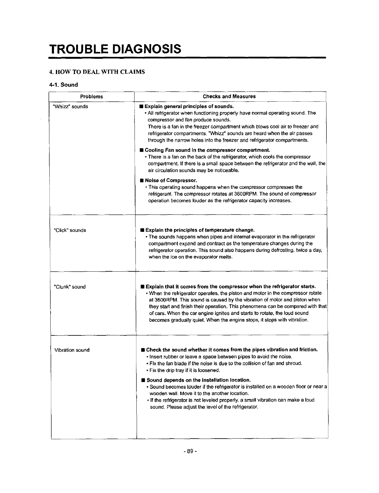
TROUBLE DIAGNOSIS
4. HOW TO DEAL WITH CLAIMS
4-1. Sound
Problems Checks and Measures
"Whizz" sounds
"Click" sounds
"Clunk" sound
Vibration sound
•Explain general principles of sounds.
•A/I refrigerator when functioning prepedy have normal operating sound. The
compressor and fan produce sounds.
There is a fan in the freezer compartment which blows coo] air to freezer and
refrigerator compartments. "Whizz" sounds are heard when the air passes
through the narrow holes into the freezer and refrigerator compartments.
•Cooling Fan sound in the compressor compartment.
•There is a fan on the back of the refrigerator, which cools the compressor
compartment. If there is a small space between the refrigerator and the wall, the
air circulation sounds may be noticeable.
•Noise of Compressor.
•This operating sound happens when the compressor compresses the
refrigerate. The compressor rotates at 3600RPM. The sound of compressor
operation becomes louder as the refrigerator capacity increases.
•Explain the principles of temperature change.
• The sounds happens when pipes and internal evaporator in the refrigerator
compartment expand and contract as the temperature changes during the
refrigerator operation. This sound also happens during defrosting, twice a day,
when the ice on the evaporator melts.
•Explain that it comes from the compressor when the refrigerator starts,
•When the refrigerator operates, the piston and motor in the compressor rotate
at 3600RPM. This sound is caused by the vibration of motor and piston when
they start and finish their operation. This phenomena can be compared with tha
of cars. When the car engine ignites and starts to rotate, the loud sound
becomes gradually quiet. When the engine stops, it stops with vibration.
• Check the sound whether it comes from the pipes vibration and friction.
• Insert rubber or leave a space between pipes to avoid the noise.
•Fix the fan blade ifthe noise is due to the collision of fan and shroud.
•Fix the drip tray if it is loosened.
•Sound depends on the installation location.
•Sound becomes louder if the refdgerator is installed on a wooden floor or near
wooden wall. Move itto the another location,
• If the refrigerator is not leveled properly, asmall vibration can make a loud
sound. Please adjust the level of the refdgerston
-89 -

TROUBLE DIAGNOSIS
Problems
Sounds of water flowing
"Click"sounds
Noise of ice maker operation
(applicable to model with ice maker
- Noise produced by ice dropping
and hitting ice bank,
-Noise from motor sounds "Whizz".
Noise when supplying water.
Noise wben supplying ice.
Checks and Measures
• Explain the flow of refrigerant.
•When the refrigerator stops, the water flowing sound happens.
This sound happens when the liquid or vapor refrigerant flows from the
evaporator to compressor.
•Explain the characteriistics of moving pads.
•This noise comes from the MICOM controller's sw_tch on the top of the
refrigerator when it is turned on and Off.
•Explain the procedure and principles of ice maker operation.
•Automatic ice maker repeats the cycle of water supplying _-_icemaking -, ice
ejection. When water is supplied, the water supply valve in the machine room
makes sounds like "Whizz" and water flowing also makes sound. When water
freezes to ice, freezing sounds such as "click, click" are heard. When ice is
being ejected, sounds like "Whizz" produced by a motor to rotate an ice tray
and ice dropping and hitting ice bank sounds are also heard.
•Explain the principles of water supplied to dispenser.
•When the water supply button in the dispenser is pressed, the water supply
valve in the compressor compartment opens and let the water flow to the water
tank in the lower part of the refrigerator compartment. The water is dispensed
by this pressure. When this happens, motor sound end water flowing sound are
heard.
•Explain the principles of ice supply and procedure of crushed ice making in a
dispenser.
• When ice cube button is pressed, ice stored in the ice bank is moved by a Helix
Pusher and dispensed. If crushed ice button is pressed, the cube ice is
crushed. When this happens, ice crushing and hitting ice bank sounds are
heard,
- 90 -
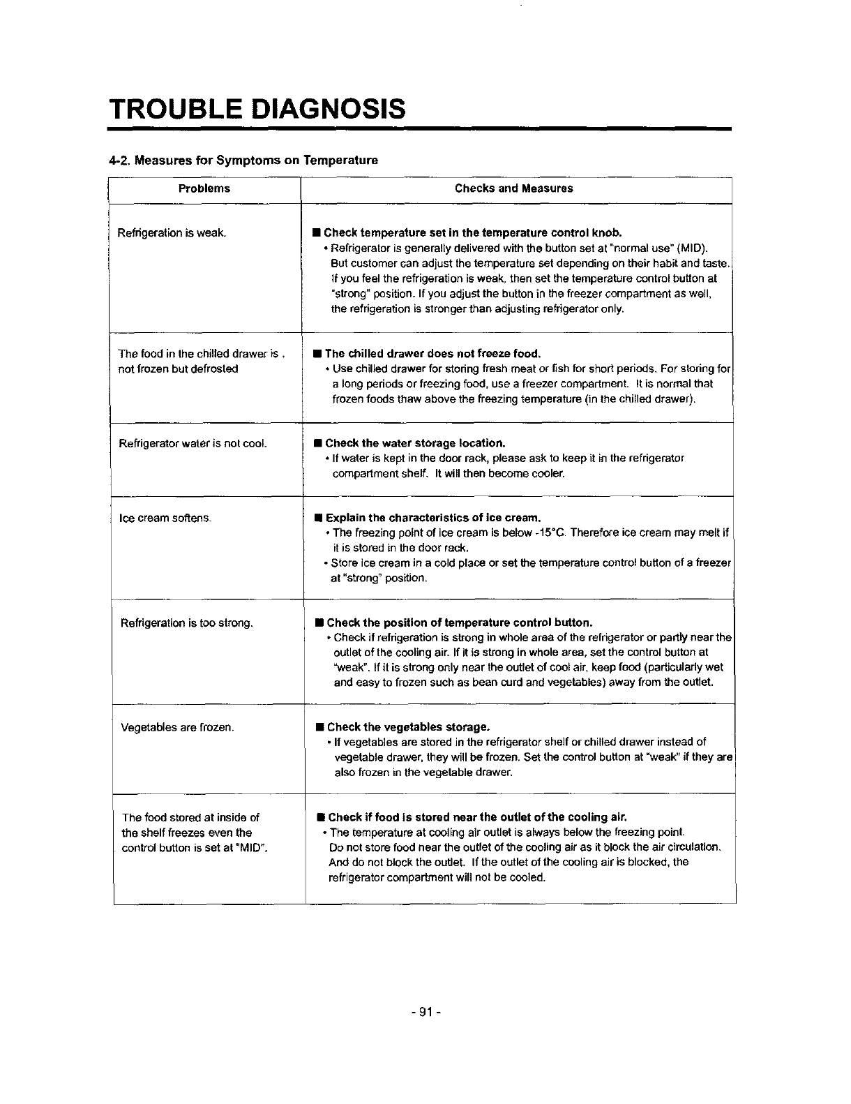
TROUBLE DIAGNOSIS
4-2, Measures for Symptoms on Temperature
Problems Checks and Measures
Refrigeration is weak.
The food in the chilled drawer is.
not frozen but defrosted
Refrigerator wa[er is not cool.
Ice cream softens.
Refrigeration is too strong.
Vegetables are frozen.
The food stored at inside of
the shelf freezes even the
control button is set at "MID".
•Check temperature set in the temperature control knob.
• Refrigerator is generally delivered with the button set at "normal use" (MID).
But customer can adjust the temperature set depending on their habit and taste.
If you feel the refrigeration is weak, then set the temperature control button at
=strong" position. If you adjust the button in the freezer compartment as well,
the refrigeration is stronger than adjusting refrigerator only.
•The chilled drawer does not freeze food,
•Use chilled drawer for storing fresh meat or fish for short periods, For storing for
a long periods or freezing food, use a freezer compartment. It is normal that
fl'ozen foods thaw above the freezing temperature (in the chilled drawer).
•Check the water storage location.
•If water is kept inthe door rack, please ask to keep it in the refrigerator
compartment shelf, It will then become cooler.
•Explain the characteristics of ice cream.
•The freezing point of ice cream is below -15°C. Therefore ice cream may melt if
it is stored in the door rack.
•Store ice cream in a cold place or set the temperature control button of a freezer
at "strong" position.
•Check the position of temperature control button.
•Check if refrigeration is strong in whole area of the refrigerator or partly near the
outlet of the cooling air. If it is strong in whole area, set the control button at
"weak". If it is strong only near the outlet of cool air, keep food (particularly wet
and easy to frozen such as bean curd and vegetables) away from the outlet.
•Check the vegetables storage.
•If vegetables are stored in the refrigerator shelf or chilled drawer instead of
vegetable drawer, they will be frozen. Set the control button at =weak" if they are
also frozen in the vegetable drawer.
•Check if food is stored near the outlet of the cooling air.
•The temperature at cooling air outlet is always below the freezing point.
Do not store food near the outlet of the cooling air as it block the air circulation,
And do not block the outlet. If the outlet of the cooling air is blocked, the
refrigerator compartment will not be cooled.
-91 -
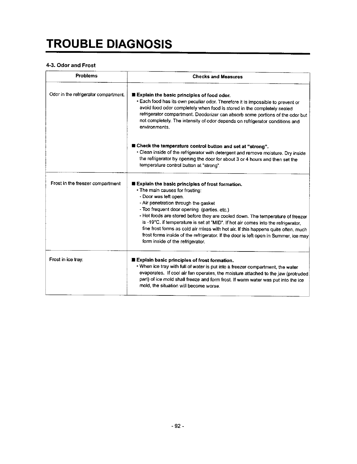
TROUBLE DIAGNOSIS
4-3. Odor and Frost
Checks and Measures
Problems
Odor intherefrigeratorcompartment.
Frost in the freezer compartment
Frost in ice hay.
• Explain the basic principles of food odor.
• Each food has its own peculiar odor. Therefore it is impossible to prevent or
avoid food odor completely when food is stored in the completely sealed
refrigerator compartment, Deodorizer can absorb some portions of the odor but
not completely. The intensity of odor depends on refrigerator conditions and
environments.
•Check the temperature control button and set at "strong".
•Clean inside of the refrigerator with detergent and remove moisture. Dry inside
the refrigerator by opening the door for about 3 or 4 hours and then set the
temperature control button at "strong'.
•Explain the basic principles of frost formation.
• The main causes for fmstthg:
-Door was left open.
-Air penetration through the gasket
-Too frequent door opening. (parties. etc.)
- Hot foods are stored before they are cooled down. Tee temperature of freezer
is -19°C. if temperature is set at =MID". If hot air comes into the refrigerator,
fine frost forms as cold air mixes with hot air. If this happens quite often, much
frost forms inside of the mfrigerater. If the door is left open in Summer, ice ma
form inside of the refrigerator.
•Explain basic principles of frost formation.
•When ice tray with full of water is put into a freezer compartment, the water
evaporates. If cool air fan operates, the moisture attached to the jaw (protruded
part) of ice mold shall freeze and form frost. If warm water was put into the ice
mold, the situation will become worse.
-92 -
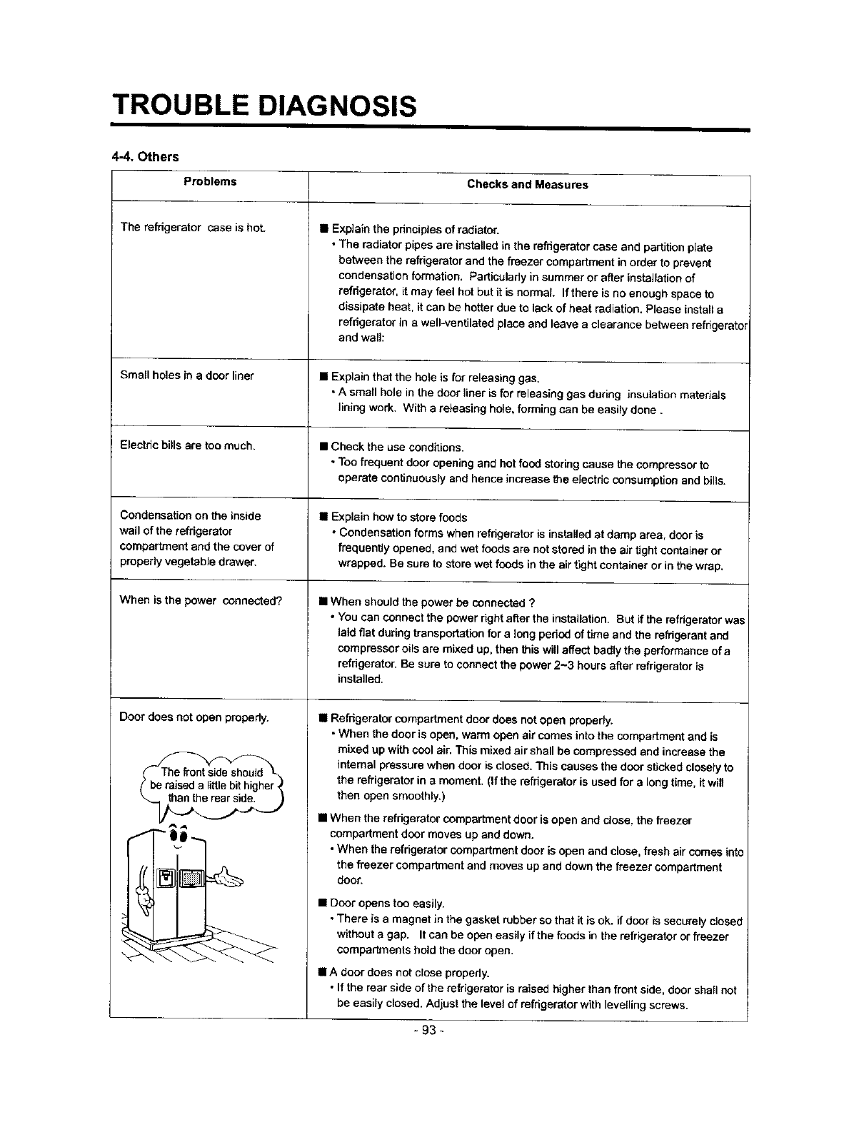
TROUBLE DIAGNOSIS
4-4. Others
Problems Checks and Measures
The refrigerator case is hot. •Explaln the principles of radiator.
• The radiator pipes are installed in the refrigerator case and partition plate
between the refrigerator and the freezer compartment in order to prevent
condensation formation. Particularly in summer or after installation of
refrigerator, it may feel hot but it is normal If there is no enough space to
dissipate heat, it can be hotter due to lack of heat radiation. Please install a
refrigerator in a well-ventilated place and leave aclearance between refdgeretol
and wall:
Small holes in a door liner •Explain that the hole is for releasing gas.
• A small hole in the door liner is for releasing gas during insulation materials
lining work. With a releasing hole, forming can be easily done.
Electric bills are too much. • Check the use conditions.
• Too frequent door opening and hot food storing cause the compressor to
operate continuously and hence increase the electdc consumption and bills.
Condensation on the inside • Explain how to store foods
wail of the refrigerator • Condensation forms when refrigerator Ls installed at damp area, door is
compartment and the cover of frequently opened, and wet foods are not stored in the air tight container or
properly vegetable drawer, wrapped. Be sure to store wet foods in the air tight container or in the wrap.
When is the power connected?
Door does not open propedy.
• When should the power be connected ?
• You can connect the power right after the installation. But if the refrigerator was
laid flat during transportation for a long pedod of time and the refdgerent and
compressor oils are mixed up, then this will affect badly the performance of a
refrigerator. Be sure to connect the power 2-3 hours after refrigerator is
installed.
•Refrigerator compartment door does not open preperly.
•When the door is open, warm open air comes into the compartment and is
mixed up with cool air. This mixed air shall be compressed and increase the
internal pressure when door is closed. This causes the door sticked closely to
the refrigerator in a moment. (if the refdgeretor is used for a long time, it will
then open smoothly.)
•When the refdgerator compartment door is open and dose. the freezer
compartment door moves up and down.
• When the refrigerator compartment door is open and close, fresh air comes into
the freezer compartment and moves up and down the freezer compartment
door.
• Door opens too easily.
•There is a magnet in the gasket rubber so that it is ok. if door is securely closed
without a gap. It can be open easily if the foods lo the refrigerater or freezer
compartments hold the door open.
•Adoor does not close properly.
• If the rear side of the refrigerator is raised higher than front side, door shall not
be easily closed. Adjust the level of refrigerator with levelling screws.
-93-
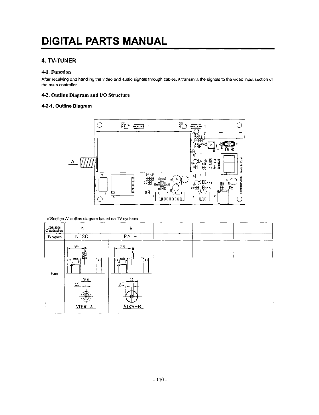
DIGITAL PARTS MANUAL
4, W-TUNER
4-1. Function
After receiving and handling the video and audio signals through cables, it transmits the signals to the video input section of
the main controller.
4-2. Outline Diagram and 1/O Structure
4-2.1. Outline Diagram
F',_,t
_888B_
bBf .I _ "
<"Section A" outline diagram based on T_/system>
C_n A
TMsystem NT S C
F0_tQ
VIEW-A
B
PAL-I
3.55 __.
VIEW-B
- 110 -

DIGITAL PARTS MANUAL
4-2-2. I/O Structure
CONNECTOR PIN NO. I/O SYMBOL
1 GND GND
2Output AUDIO-L
P1 3 Output AUDIO-R
4GND GND
1Input SDA
2 Input SCL
3 Input GND
4 Input GPIO13
P2 5 Input GPIO12
6 Input GND
7 Input +12V
8 Input -5V
9 Input GPIO15
10 Input GPIO14
P3 1,2 Output TV OUT
DESC_P_ON
GND
AUDIO LEFT OUTPUT
AUDIO RIGHT OUTPUT
GND
12C-BUS Serial Data
12C Serial Clock
GND
General Purpose I/O 13
General Purpose I/O 12
GND
DC+12V
DC-5V
General Purpose I/O 15
General Purpose I/O 14
TV VIDEO Signal Output
4-3. SPEC of parts
1. Operating Environment
- Operating temperature: -10°C - 60°C
-Operating humidity: 0 - 95% (under 35°C condition)
2, Storage Environment
- Storage temperature: -25°C ~ 85°C
-Storage humidity: 95% (under35°C condition)
-111 -
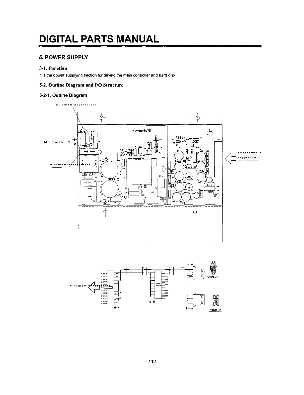
DIGITAL PARTS MANUAL
5. POWER SUPPLY
5-1, Function
It is thepower supplyingsectionfor driving the main controller and hard disk.
5-2. Outline Diagram and 1/O Structure
5-2-1. Outline Diagram
AC P_WER IN
I I
i _o#_Io_we i
., ®
........
A __,_ _-_
-112-
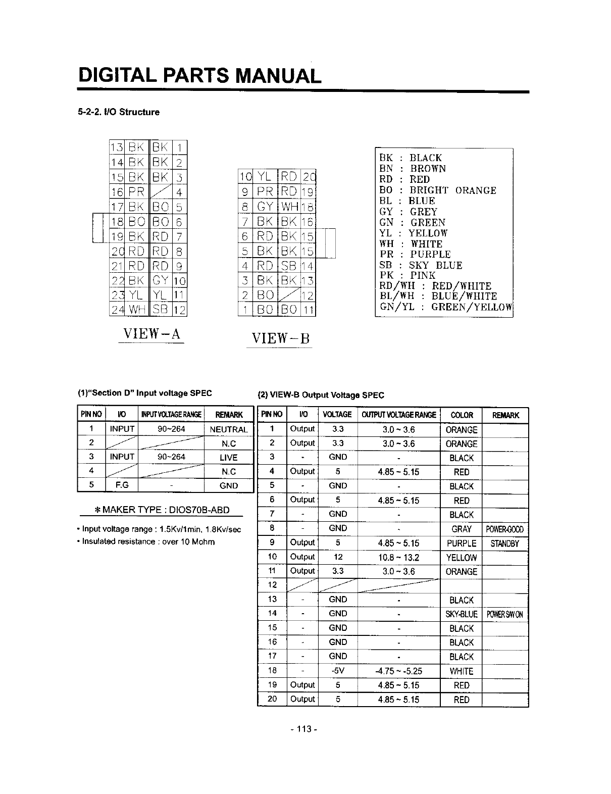
DIGITAL PARTS MANUAL
5-2-2. I/O Structure
5 BK BK 1
14 BK BK 2
!_ BK BK 5 1C YL RD 2C
16 PR _ 4 9 PR RD 19
1/ BK BO 5 8 GY WIll8
18 BO BO 6 7 BK BK 16
19 BK RD 7 6 RD BK 15
2C RD RD 8 5 BK BK 15
21 RD RD 9 4 RD SB 14
21 BK GY 10 5 BK BK 15
2._ YL YL 11 2 BO _12
2z WH SB 12 1 BO BO 11
VIEW-A VIEW-B
BK : BLACK
BN : BROWN
RD : RED
BO : BRIGHT ORANGE
BL : BLUE
GY :GREY
GN : GREEN
YL : YELLOW
WH : WHITE
PR : PURPLE
SB : SKY BLUE
PK :PINK
RD/WH :RED/WHITE
BL/WH :BLUE/WHITE
GN/YL :GREEN/YELLOW
(1)"Section D" Input voltage SPEC
PINNO
I
2
3
4
5
K) INRJTVOLTAGERAk_E REMARK
INPUT 90-264 NEUTRAL
N.C
INPUT 90~264 LIVE
No
F.G GND
:1:MAKER TYPE : DIOS70B-ABD
Input voltage range : 1.5Kv/lmin, 1 .SKy/see
Insulated resistance : over 10 Mohm
(2) VIEW-B Output Voltage SPEC
PINNO I/O
1 Output
2Output
3
4Output
5
6Output
7
8
9 Output
10 Output
11 Output
12
VOLTAGEOUTPUTVOLTAGERANGECOLOR REMARK
3.3 3.0 ~ 3.6 ORANGE
3.3 3.0 ~3.6 ORANGE
GND BLACK
5 4.85 ~ 5.15 RED
GND BLACK
5 4,85 - 5.15 RED
GND BLACK
GND GRAY P0_R-G00D
5 4.85 ~ 5.15 PURPLE STANDBY
12 10.8 ~13.2 YELLOW
3.3 3.0 - 3.6 ORANGE
13 GND BLACK
14 GND SKY-BLUE
15 GND BLACK
16 GND BLACK
17 GND BLACK
18 -5V 4.75 ~ -5.25 WHITE
19 Output 5 4.85- 5.15 RED
20 Output 5 4.85 ~ 5.15 RED
POV_R_VON
-113-
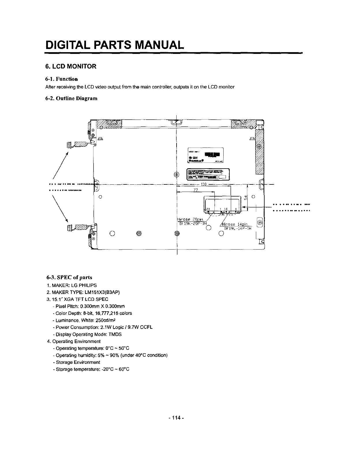
DIGITAL PARTS MANUAL
6. LCD MONITOR
6-1. Function
After receiving the LCD video output from the main controller, outputs it on the LCD monitor
6-2. Outline Diagram
/
•••••*oQ QP6DbI****
\oh_- /r2!
o ® ? o
I
I
_.m
6-3. SPEC of parts
1. MAKER: LG PHILIPS
2. MAKER TYPE: LM 151X3(B3AP)
3, 15.1 _XGA TFT LCD SPEC
- Pixel Pitch: 0.300mm X 0.300mm
-Color Depth: 8-bit, 16,777,216 colors
- Luminance, White: 260cd/m2
-Power Consumption: 2.1W Logic /9.7W CCFL
Display Operating Mode: TMDS
4. Operating Environment
- Operating temperature: 0°C ~ 50°C
- Operating humidity: 5% ~ 90% (under 40°C condition)
-Storage Environment
- Storage temperature: -20°C ~ 60°C
-114-
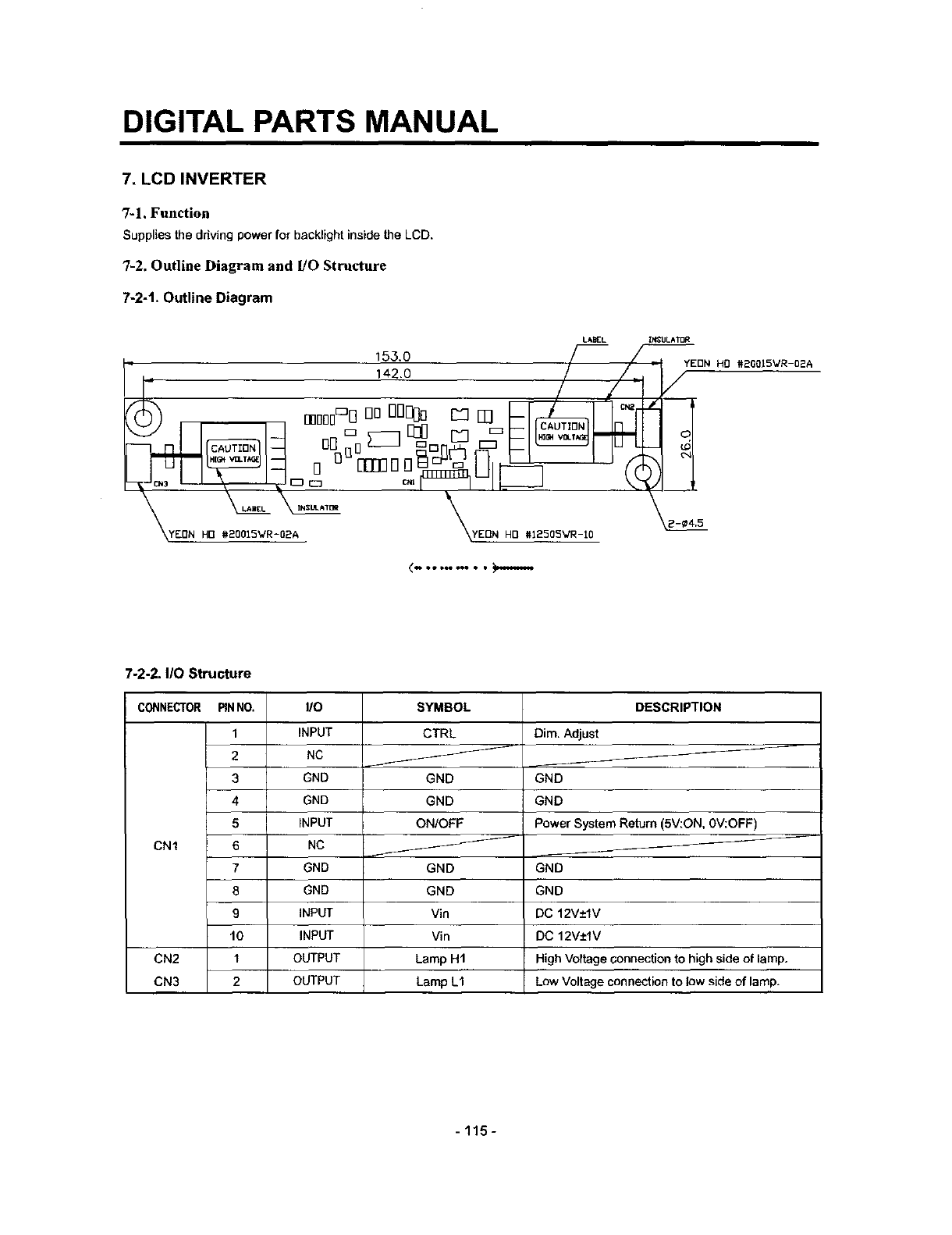
DIGITAL PARTS MANUAL
7. LCD INVERTER
7-1. Function
Supplies the driving power for backlight inside the LCD.
7-2. Outline Diagram and l/O Structure
7-2-t. Outline Diagram
q
LABEL Ii_'_JLA_DR
153.0 //_ //-w
142.o / /.,
-. ! /0/
=
_-_ \
<.. se _oo ooQ • •
YEON HO #20015VRIO2A
21¢4,5
7-2-2. IIOStructure
CONNECTOR PINNO.
1
2
3
4
5
CN1 6
7
8
9
t0
CN2 1
CN3 2
I/O
INPUT
NC
GND
GND
INPUT
NC
GND
GND
INPUT
INPUT
OUTPUT
OUTPUT
SYMBOL
CTRL
GND
GND
ON/OFF
GND
GND
Vin
Vin
Lamp H1
Lamp L1
DESCRIPTION
Dim. Adjust
GND
GND
Power System Return (5V:ON, 0V:OFF)
GND
GND
DC 12V±lV
DC 12V±IV
HighVoltage connection to high aideof lamp.
Low Voltage connection to low side of lamp.
- 115 -
DIGITAL PARTS MANUAL
7-3. SPEC of parts
1. Maker: LG Electronics
2. Inverter Type: NMC1507-02
3. Maker Type: 6632Z-1507B
4. Inverter SPEC
- Input Supply Voltage: DC 11~13V
- Input Current: 1.1A
-Input Power: 13.2W
- Output Voltage: 616Vrrns
-Output Current: 9.0mArrns
- Output Power: 12W (2 lamps total)
- Input Signal Voltage: -0.3V ~ 6,0V
5. Operating Environment
-Operating temperature: 0°C - 60°C
- Operating humidity: 10% ~85%
6. Storage Environment
- Storage temperature: -30°C - 80°C
-116-
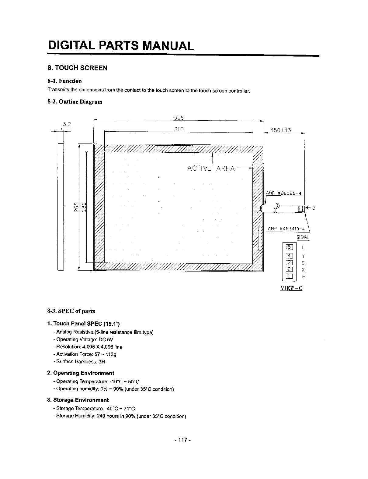
DIGITAL PARTS MANUAL
8. TOUCH SCREEN
8-1, Function
Transmits the dimensions from the contact to the touch screen to the touch screen controller.
8-2, Outline Diagram
5.2
556
310
ACTF\'E
450±13
AHP #48741D-_
31GNAL
Y
S
×
H
VIEW-C
8-3. SPEC of parts
1, Touch Panel SPEC (15.1")
-Analog Resistive (5-line resistance film type)
-Operating Voltage: DC 5V
-Resolution: 4,096 X 4,096 line
-Activation Force: 57 ~ 113g
- Surface Hardness: 3H
2. Operating Environment
-Operating Temperature: -10"C -50°C
- Operating humidity; 0% ~ 90% (under 35°C condition)
3. Storage Environment
-Storage Temperature:_10°C~ 71°C
-Storage Humidity:240 hoursin 90% (under35°C condition)
-117-

DIGITAL PARTS MANUAL
9. TOUCH CONTROLLER
9-1. Function
After receiving and handling the touchdimensiOnsfrom thetouch screen,transmits to the main controller
9-2, Outline Diagram and I/O Structure
9-2-1. Outline Diagram
FACTDRYJUMPERSETTING
IN- J7,BUT- JO~J6,JS~Jtt
2,5rimPi±ch Angle ±ype
Doub[eLinePinHe_derConn,
53
46
PHILIPS
4--¢4
FIN RERO_B
P3 _P4
I
VIEW-A
I
MOLEX
T
A
\ MOLEX #6373-2
9-2-2. I/O Structure
CONNECTOR PiNNO.
1
2
3
4
5
P2 6
7
8
9
10
1
P4
2
I/O SYMBOL DESCRIPTION
INPUT DCD Data Carder Detect
INPUT DSR Data Sct Ready
INPUT RxD Receive Data
INPUT RTS Ready To Send
INPUT TxD Transmit Data
INPUT CTS Clear To Send
INPUT DTR Data Terminal Ready
N/C N/C N/C
GND GND Ground
PIN REMOVED
INPUT +5V DC +5V
GND GND Ground
-118-
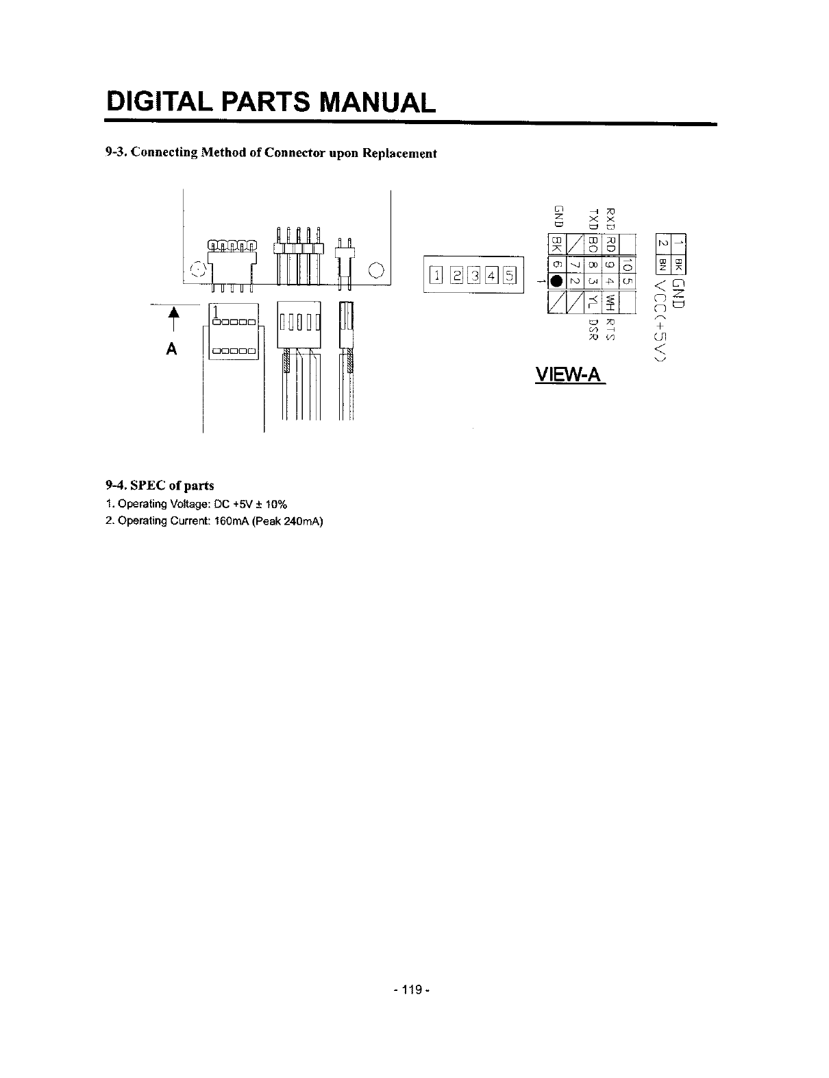
DIGITAL PARTS MANUAL
9-3. Connecting Method of Connector upon Replacement
00[:300
A00000
Z X X
O3 _J O0 LO
7O +
,_ (/_ O r]
<
VIEW-A
9-4. SPEC of parts
1. Operating Voltage: DC +5V + 10%
2. Operating Current: 160mA (Peak 240mA)
-119-

DIGITAL PARTS MANUAL
10. CCD (CHARGE COUPLED DEVICE) CAMERA
10-1. Function
Changes the external video signal received through the lens into an electric signal and transmits to main controller
10-2. Outline Diagram and 1/O Structure
10-2-1. Outline Diagram
32.6
28.1
138
\ 4-_2.2
3.51 125 5.2
CNI
JSf NFH_SB SRS_-TB J
0 IZ ]qC
_1 _ o_r_
n [Zig I I_
_ gl io L_
_LJ o LdS_
O= D cz=sC
ON2
10-2-2. I/O Structure
CONNECTOR PINNO. I/O SYMBOL DESCRIPTION
1 INPUT +12V DC +12V
2GND GND GND
CN 1 3 OUTPUT VIDEO CAMERA VIDEO OUT
4 GND GND CAMERA VIDEO GND
5 OUTPUT MIRROR CAMERA MIRROR
10-3. SPEC of parts
1. CCD Camera Module SPEC
-Operating Voltage: DC 12 ± lV
- Current Consumption: Max. 100mA + 10%
- image Sensor: 1/4 inch 270,000
-Effective Pixel: 512(H) X 492(V)
- Signal System: NTSC
- Horizontal Frequency: 15.734kHz
- Vertical Frequency: 59.94kHz
- SIN Ratio: 48dB rain.
- Video Output: Analog Composite
2. Operating Environment
- Operating temperature:
- 120 -
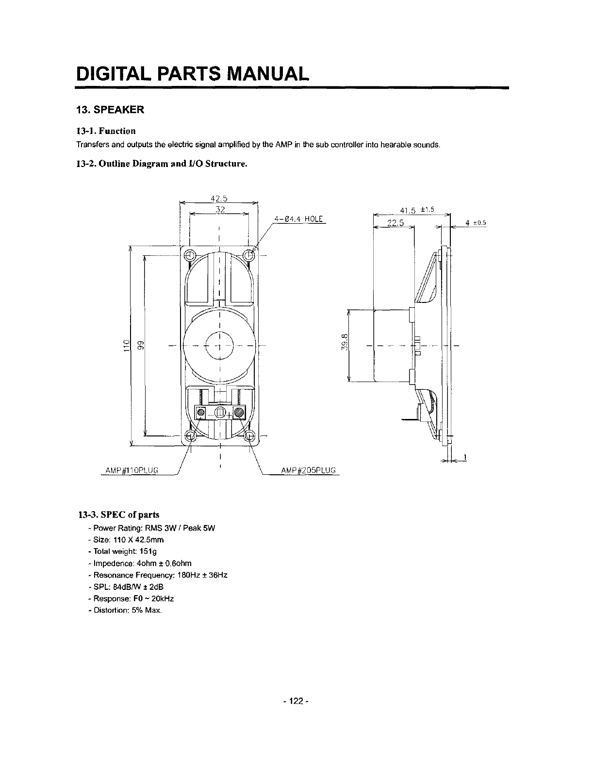
DIGITAL PARTS MANUAL
13. SPEAKER
13-1. Function
Transfers and outputs the electric signal amplified by the AMP in the sub controller into hearable sounds.
13-2. Outline Diagram and lifo Structure.
AMP#110PLUG
42.5
4-04.4 HOLE
/
AMP#205PLUG
oc
t_,
41.5 ±t5
4 ±o5
13-3. SPEC of parts
- Power Rating: RMS 3W /Peak 5W
- Size: 110 X 42.5mm
- Total weight: 151g
- Impedence: 4ohm ± 0.6ohm
- Resonance Frequency: 180Hz -+36Hz
- SPL: 84dB/W ± 2dB
- Response: F0 ~ 20kHz
-Distortion: 5% Max.
-122 -
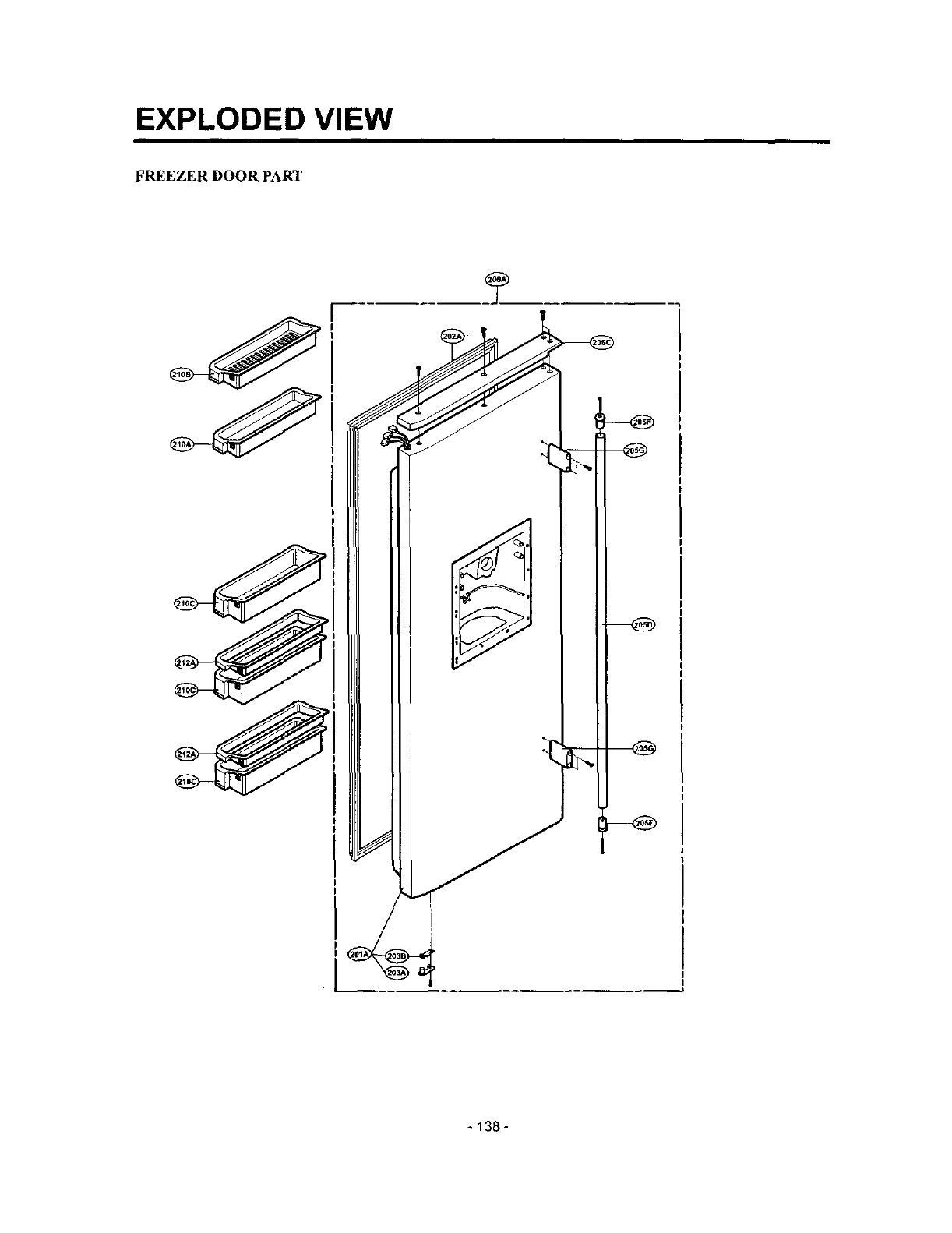
EXPLODED VIEW
FREEZER DOOR PART
* 138 -

EXPLODED VIEW
REFRIGERATOR DOOR PART
- 139-
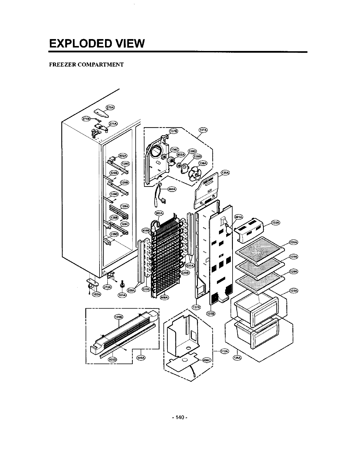
EXPLODED VIEW
FREEZER COMPARTMENT
I•
1
I
I
I
I
i
- 140 -
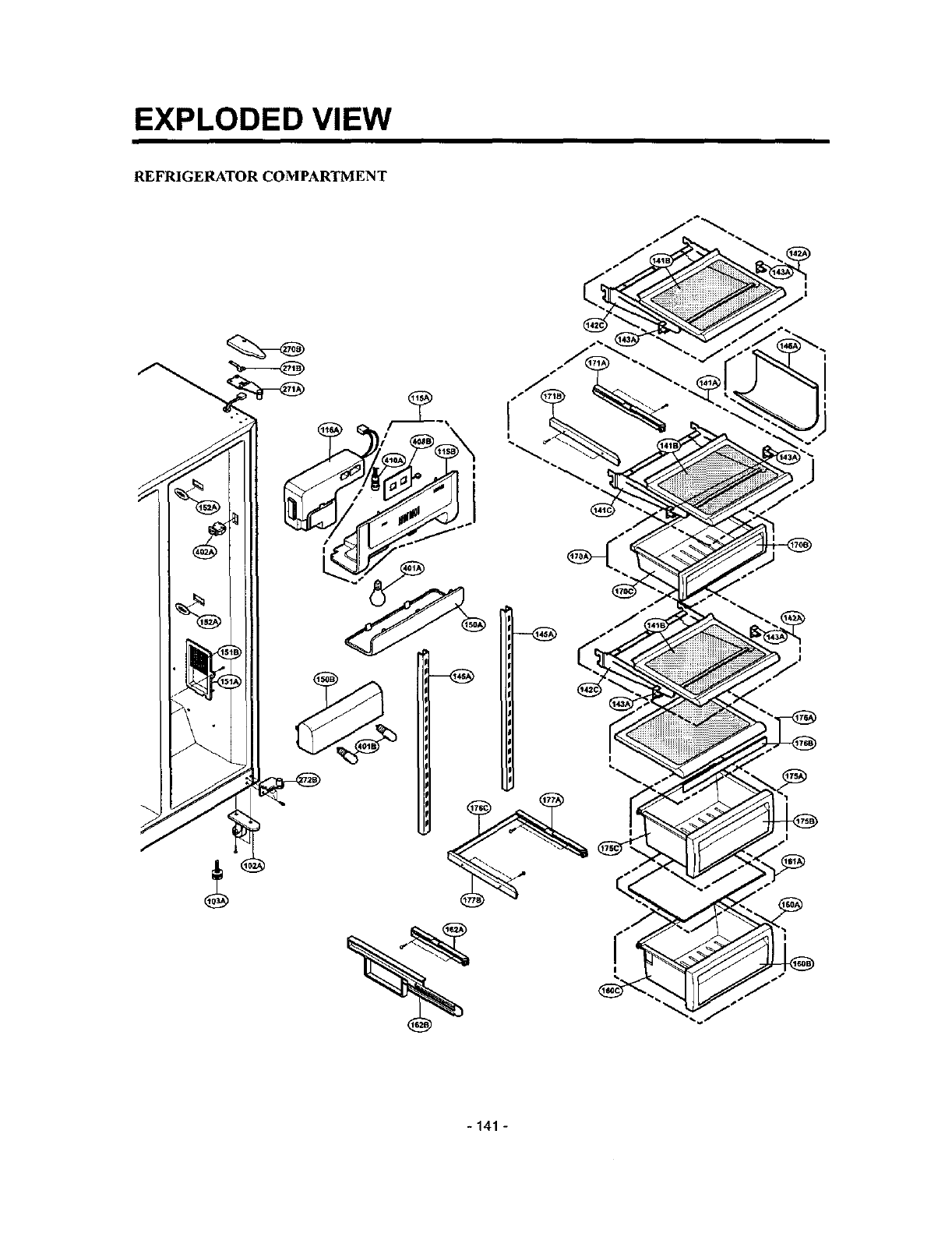
EXPLODED VIEW
REFRIGERATOR COMPARTMENT
-141 -
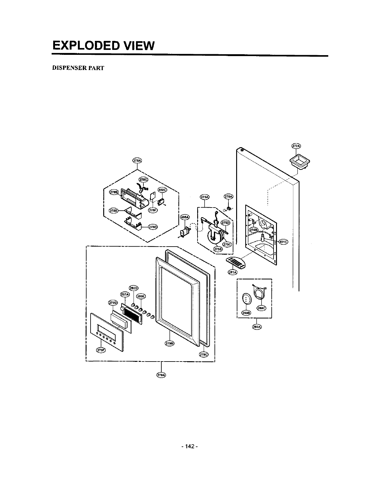
EXPLODED VIEW
DISPENSER PART
-142 -

EXPLODED VIEW
ICE & WATER PART
-143 *

EXPLODED VIEW
MACHINE COMPARTMENT
- 144 -
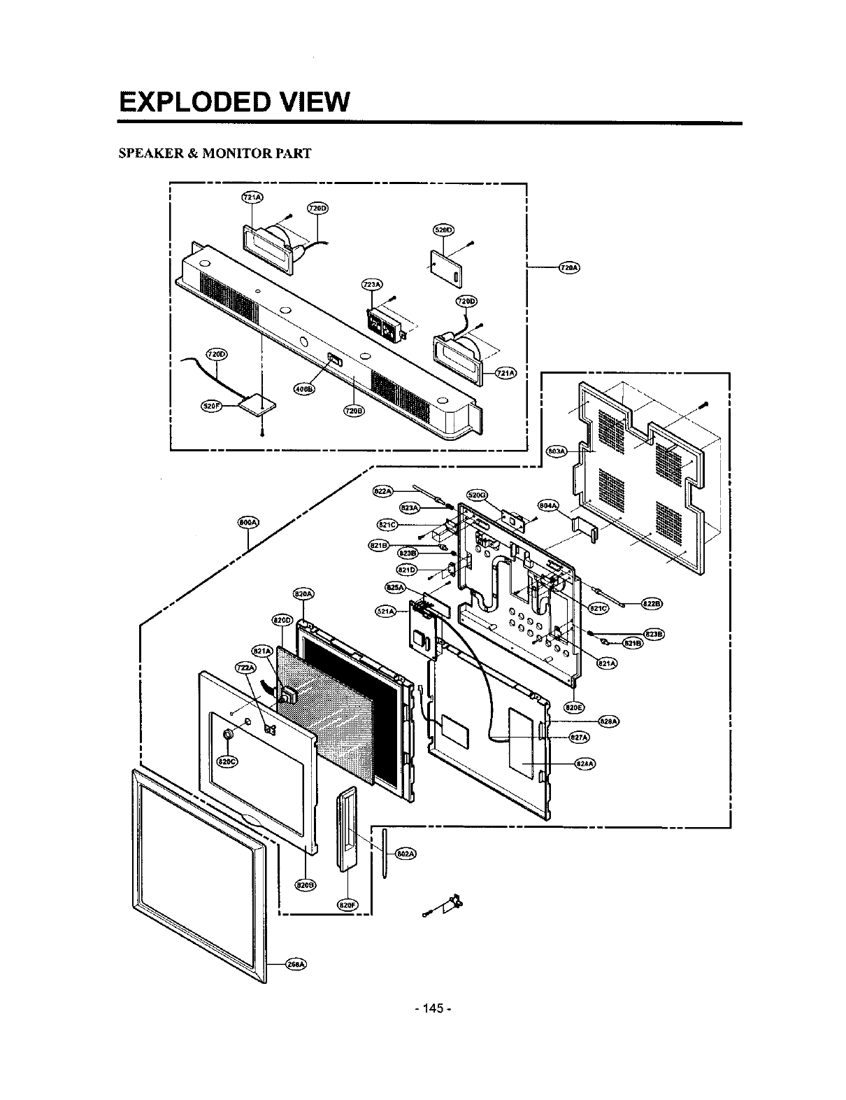
EXPLODED VIEW
SPEAKER & MONITOR PART
?
J
- 145 -
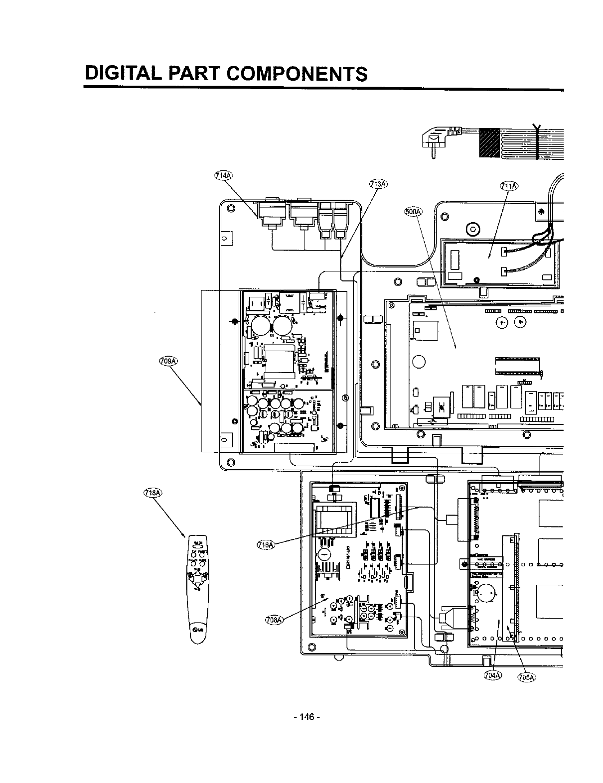
DIGITAL PART COMPONENTS
\
®
0
\
®®
oL
O0 00000
- 146 -
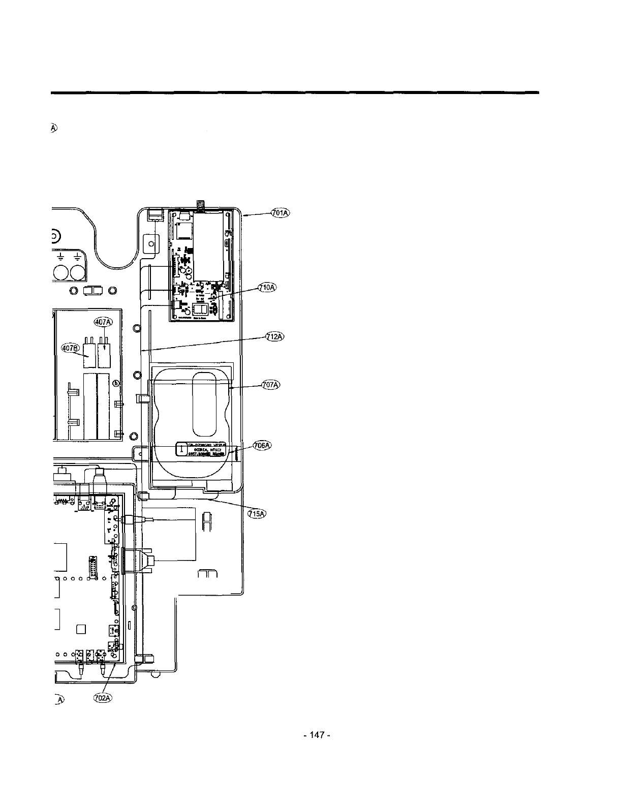
- 147-
