LINKSYS WAG325NV2 Wireless-N ADSL2+ Gateway User Manual Book
LINKSYS LLC Wireless-N ADSL2+ Gateway Book
LINKSYS >
Contents
- 1. User Manual 1
- 2. User Manual 2
User Manual 1
Model No.
ADSL2+ Gateway
Wireless-N
WAG325N V2
User Guide
WIRELESS
GHz
2.4

Wireless-N ADSL2+ Gateway
Copyright and Trademarks
Specifications are subject to change without notice. Linksys is a registered trademark or trademark of Cisco
Systems, Inc. and/or its affiliates in the U.S. and certain other countries. Copyright © 2006 Cisco Systems, Inc. All
rights reserved. Other brands and product names are trademarks or registered trademarks of their respective
holders.
How to Use this Guide
Your Guide to the Wireless-N ADSL2+ Gateway has been designed to make understanding networking with the
Gateway easier than ever. Look for the following items when reading this User Guide:
In addition to these symbols, there are definitions for technical terms that are presented like this:
Also, each figure (diagram, screenshot, or other image) is provided with a figure number and description, like
this:
Figure numbers and descriptions can also be found in the “List of Figures” section in the “Table of Contents”.
This exclamation point means there is a Caution or
Warning and is something that could damage your
property or the Gateway.
word: definition.
This checkmark means there is a Note of interest and
is something you should pay special attention to while
using the Gateway.
This question mark provides you with a reminder about
something you might need to do while using the Gateway.
Figure 0-1: Sample Figure Description
WAG325N-EU-UG-61003NC BW

Wireless-N ADSL2+ Gateway
Table of Contents
Chapter 1: Introduction 1
Welcome 1
What’s in this User Guide? 2
Chapter 2: Planning Your Network 4
The Gateway’s Functions 4
IP Addresses 4
Chapter 3: Getting to Know the Wireless-N ADSL2+ Gateway 6
Ports and Reset Button on Back Panel 6
LEDs on Front Panel 7
Chapter 4: Connecting the Wireless-N ADSL2+ Gateway 8
Overview 8
Wired Connection to a Computer 8
Wireless Connection to a Computer 9
Chapter 5: Configuring the Wireless-N ADSL2+ Gateway 10
Overview 10
How to Access the Web-based Utility 12
The Setup Tab 12
The Wireless Tab 21
The Security Tab 29
The Access Restrictions Tab 31
The Applications and Gaming Tab 33
The Administration Tab 40
The Status Tab 46
Appendix A: Troubleshooting 50
Common Problems and Solutions 50
Frequently Asked Questions 58
Appendix B: Wireless Security 65
Security Precautions 65
Security Threats Facing Wireless Networks 65
Appendix C: Finding the MAC Address and IP Address for Your Ethernet Adapter 68
Windows 98 or Me Instructions 68
Windows 2000 or XP Instructions 69

Wireless-N ADSL2+ Gateway
Appendix D: Upgrading Firmware 70
Appendix E: Glossary 71
Appendix F: Specifications 76
Appendix G: Warranty Information 78
Appendix H: Regulatory Information 79
Appendix I: Regulatory Information 91
Appendix J: Contact Information 105

Wireless-N ADSL2+ Gateway
List of Figures
Figure 2-1: Network 4
Figure 3-1: Ports and Reset Button on Side Panel 6
Figure 3-2: LEDs on Side Panel 7
Figure 4-1: Connect the ADSL Line 8
Figure 4-2: Connect a PC 8
Figure 4-3: Connect the Power 8
Figure 4-4: Connect the ADSL Line 9
Figure 4-5: Connect the Power 9
Figure 5-1: Basic Setup 12
Figure 5-2: RFC 1483 Bridged 13
Figure 5-3: RFC 1483 Routed 14
Figure 5-4: IPoA 14
Figure 5-5: RFC 2516 PPPoE 15
Figure 5-6: RFC 2364 PPPoA 15
Figure 5-7: Bridge Mode Only 16
Figure 5-8: Optional Settings 16
Figure 5-9: DDNS - DynDNS.org 18
Figure 5-10: DDNS - TZO.com 18
Figure 5-11: Advanced Routing 19
Figure 5-12: Routing Table 20
Figure 5-13: Basic Wireless Settings 21
Figure 5-14: Wireless Security - WPA-Personal 22
Figure 5-15: Wireless Security - WPA2-Personal 22
Figure 5-16: Wireless Security - WPA-Enterprise 23
Figure 5-17: Wireless Security - WPA2-Enterprise 23
Figure 5-18: Wireless Security - RADIUS 24
Figure 5-19: Wireless Security - WEP 25
Figure 5-20: Wireless MAC Filter 26
Figure 5-21: Wireless Client List 26
Figure 5-22: Advanced Wireless Settings 27
Figure 5-23: Firewall 29
Figure 5-24: VPN Passthrough 30

Wireless-N ADSL2+ Gateway
Figure 5-25: Internet Access Policy 31
Figure 5-26: Internet Policy Summary 31
Figure 5-27: List of PCs 32
Figure 5-28: Single Port Forwarding 33
Figure 5-29: Port Range Forwarding 34
Figure 5-30: Port Triggering 35
Figure 5-31: DMZ 36
Figure 5-32: QoS 37
Figure 5-33: QoS - Online Game 38
Figure 5-34: QoS - MSN Messenger 38
Figure 5-35: QoS - YAHOO Messenger 38
Figure 5-36: QoS - Skype 38
Figure 5-37: QoS - Voice Device 38
Figure 5-38: QoS - Add a New Application (Port Range) 38
Figure 5-39: QoS - Add a New Application (MAC Address) 39
Figure 5-40: Management 40
Figure 5-41: Reporting 42
Figure 5-42: View Log 42
Figure 5-43: Diagnostics 43
Figure 5-44: Ping Test 43
Figure 5-45: Backup & Restore 44
Figure 5-46: Factory Defaults 45
Figure 5-47: Firmware Upgrade 45
Figure 5-48: Gateway 46
Figure 5-49: Local Network 47
Figure 5-50: DHCP Active IP Table 47
Figure 5-51: ARP/RARP Table 47
Figure 5-52: Wireless 48
Figure 5-53: DSL Connection 49
Figure C-1: IP Configuration Screen 68
Figure C-2: MAC Address/Adapter Address 68
Figure C-3: MAC Address/Physical Address 69
Figure D-1: Firmware Upgrade 70

1
Chapter 1: Introduction
Welcome
Wireless-N ADSL2+ Gateway
Chapter 1: Introduction
Welcome
Thank you for choosing the Wireless-N ADSL2+ Gateway. The Gateway will allow you to network wirelessly better
than ever, sharing Internet access, files and fun, easily and securely and with a greater range of up to three times
farther than standard Wireless-G.
The incredible speed of Wireless-N makes it ideal for media-centric applications like streaming video and Voice
over IP (VoIP) telephony, so your network can handle multiple data streams at the same time, with no degradation
in performance.
How does the Gateway do all of this? By connecting the Internet, as well as your computers and peripherals, to
the Gateway, then the Gateway can direct and control communications for your network. Plus, since the Gateway
is wireless, Internet access can be shared over the wireless broadcast as well as the wired network.
Use wireless security to secure your wireless network while the whole network is protected through a Stateful
Packet Inspection (SPI) firewall and Network Address Translation (NAT) technology. The Gateway also offers VPN
passthrough and other features, which can be configured through the easy-to-use, browser-based utility.
But what does all of this mean?
Networks are useful tools for sharing Internet access and computer resources. You can access one printer from
different computers and access data located on another computer’s hard drive. Networks are even used for
playing multiplayer video games. So, networks not only are useful in homes and offices, but also can be fun.
PCs on a wired network create a LAN, or Local Area Network. They are connected with Ethernet cables, which is
why the network is called “wired”. PCs equipped with wireless cards or adapters can communicate without
cumbersome cables. By sharing the same wireless settings, within their transmission radius, they form a
wireless network. This is sometimes called a WLAN, or Wireless Local Area Network. Since the Gateway has
wireless capabilities, it can bridge your wired and wireless networks, letting them communicate with each other.
Linksys recommends using the Setup CD-ROM for first-time installation of the Gateway. If you do not wish to run
the Setup Wizard on the Setup CD-ROM, then use the instructions in this Guide to help you connect the Gateway,
set it up, and configure it to bridge your different networks. These instructions should be all you need to get the
most out of the Wireless-N ADSL2+ Gateway.
lan (local area network): The computers and
networking products that make up the network in
your home or office.
nat (network address translation): NAT technology
translates IP addresses of a local area network to a
different IP address for the Internet.
spi (stateful packet inspection) firewall: a technology
that inspects incoming packets of information before
allowing them to enter the network.
firewall: Security measures that protect the
resources of a local network from intruders.
network: a series of computers or devices
connected for the purpose of data sharing,
storage, and/or transmission between users
802.11g: an IEEE wireless networking standard
that specifies a maximum data transfer rate of
54Mbps, an operating frequency of 2.4GHz, and
backward compatibility with 802.11b devices.

2
Chapter 1: Introduction
What’s in this User Guide?
Wireless-N ADSL2+ Gateway
What’s in this User Guide?
This user guide covers the steps for setting up and using the Wireless-N ADSL2+ Gateway.
• Chapter 1: Introduction
This chapter describes applications of the Wireless-N ADSL2+ Gateway and this User Guide.
• Chapter 2: Planning Your Network
This chapter describes the basics of networking.
• Chapter 3: Getting to Know the Wireless-N ADSL2+ Gateway
This chapter describes the physical features of the Gateway.
• Chapter 4: Connecting the Wireless-N ADSL2+ Gateway
This chapter instructs you on how to connect the Gateway to your network.
• Chapter 5: Configuring the Wireless-N ADSL2+ Gateway
This chapter explains how to configure the Gateway’s settings using its Web-based Utility.
• Appendix A: Troubleshooting
This appendix describes some problems and solutions, as well as frequently asked questions, regarding
installation and use of the Wireless-N ADSL2+ Gateway.
• Appendix B: Wireless Security
This appendix explains the risks of wireless networking and some solutions to reduce the risks.
• Appendix C: Finding the MAC Address and IP Address for your Ethernet Adapter.
This appendix describes how to find the MAC address for your computer’s Ethernet adapter so you can use
the MAC filtering and/or MAC address cloning feature of the Gateway.
• Appendix D: Upgrading Firmware
This appendix instructs you on how to upgrade the firmware on the Gateway if you should need to do so.
• Appendix E: Glossary
This appendix gives a brief glossary of terms frequently used in networking.
• Appendix F: Specifications
This appendix provides the technical specifications for the Gateway.
• Appendix G: Warranty Information
This appendix supplies the warranty information for the Gateway.

3
Chapter 1: Introduction
What’s in this User Guide?
Wireless-N ADSL2+ Gateway
• Appendix H: Regulatory Information
This appendix supplies the regulatory information regarding the Gateway.
• Appendix I: Contact Information
This appendix provides contact information for a variety of Linksys resources, including Technical Support.

4
Chapter 2: Planning Your Network
The Gateway’s Functions
Wireless-N ADSL2+ Gateway
Chapter 2: Planning Your Network
The Gateway’s Functions
A Gateway is a network device that connects two networks together.
In this instance, the Gateway connects your Local Area Network (LAN), or the group of computers in your home or
office, to the Internet. The Gateway processes and regulates the data that travels between these two networks.
The Gateway’s NAT feature protects your network of computers so users on the public, Internet side cannot “see”
your computers. This is how your network remains private. The Gateway protects your network by inspecting
every packet coming in through the Internet port before delivery to the appropriate computer on your network.
The Gateway inspects Internet port services like the web server, ftp server, or other Internet applications, and, if
allowed, it will forward the packet to the appropriate computer on the LAN side.
Remember that the Gateway’s ports connect to two sides. The LAN ports connect to the LAN, and the ADSL port
connects to the Internet. The LAN ports transmit data at 10/100Mbps.
IP Addresses
What’s an IP Address?
IP stands for Internet Protocol. Every device on an IP-based network, including computers, print servers, and
Gateways, requires an IP address to identify its “location,” or address, on the network. This applies to both the
Internet and LAN connections. There are two ways of assigning an IP address to your network devices. You can
assign static IP addresses or use the Gateway to assign IP addresses dynamically.
Static IP Addresses
A static IP address is a fixed IP address that you assign manually to a computer or other device on the network.
Since a static IP address remains valid until you disable it, static IP addressing ensures that the device assigned
it will always have that same IP address until you change it. Static IP addresses must be unique and are
commonly used with network devices such as server computers or print servers.
NOTE: Since the Gateway is a device that connects
two networks, it needs two IP addresses—one for
the LAN, and one for the Internet. In this User Guide,
you’ll see references to the “Internet IP address”
and the “LAN IP address.”
Since the Gateway uses NAT technology, the only IP
address that can be seen from the Internet for your
network is the Gateway’s Internet IP address.
However, even this Internet IP address can be
blocked, so that the Gateway and network seem
invisible to the Internet—see the Security - Firewall
tab in “Chapter 5: Configuring the Wireless-N
ADSL2+ Gateway.”
Figure 2-1: Network
ip (internet protocol): a protocol used to send data
over a network

5
Chapter 2: Planning Your Network
IP Addresses
Wireless-N ADSL2+ Gateway
Since you use the Gateway to share your DSL Internet connection, contact your ISP to find out if they have
assigned a static IP address to your account. If so, you will need that static IP address when configuring the
Gateway. You can get that information from your ISP.
Dynamic IP Addresses
A dynamic IP address is automatically assigned to a device on the network, such as computers and print servers.
These IP addresses are called “dynamic” because they are only temporarily assigned to the computer or device.
After a certain time period, they expire and may change. If a computer logs onto the network (or the Internet) and
its dynamic IP address has expired, the DHCP server will automatically assign it a new dynamic IP address.
DHCP (Dynamic Host Configuration Protocol) Servers
Computers and other network devices using dynamic IP addressing are assigned a new IP address by a DHCP
server. The computer or network device obtaining an IP address is called the DHCP client. DHCP frees you from
having to assign IP addresses manually every time a new user is added to your network.
A DHCP server can either be a designated computer on the network or another network device, such as the
Gateway. By default, the Gateway’s DHCP Server function is enabled.
If you already have a DHCP server running on your network, you must disable one of the two DHCP servers. If you
run more than one DHCP server on your network, you will experience network errors, such as conflicting IP
addresses. To disable DHCP on the Gateway, see the DHCP section in “Chapter 5: Configuring the Wireless-N
ADSL2+ Gateway.”
6
Chapter 3: Getting to Know the Wireless-N ADSL2+ Gateway
Ports and Reset Button on Back Panel
Wireless-N ADSL2+ Gateway
Chapter 3: Getting to Know the Wireless-N ADSL2+
Gateway
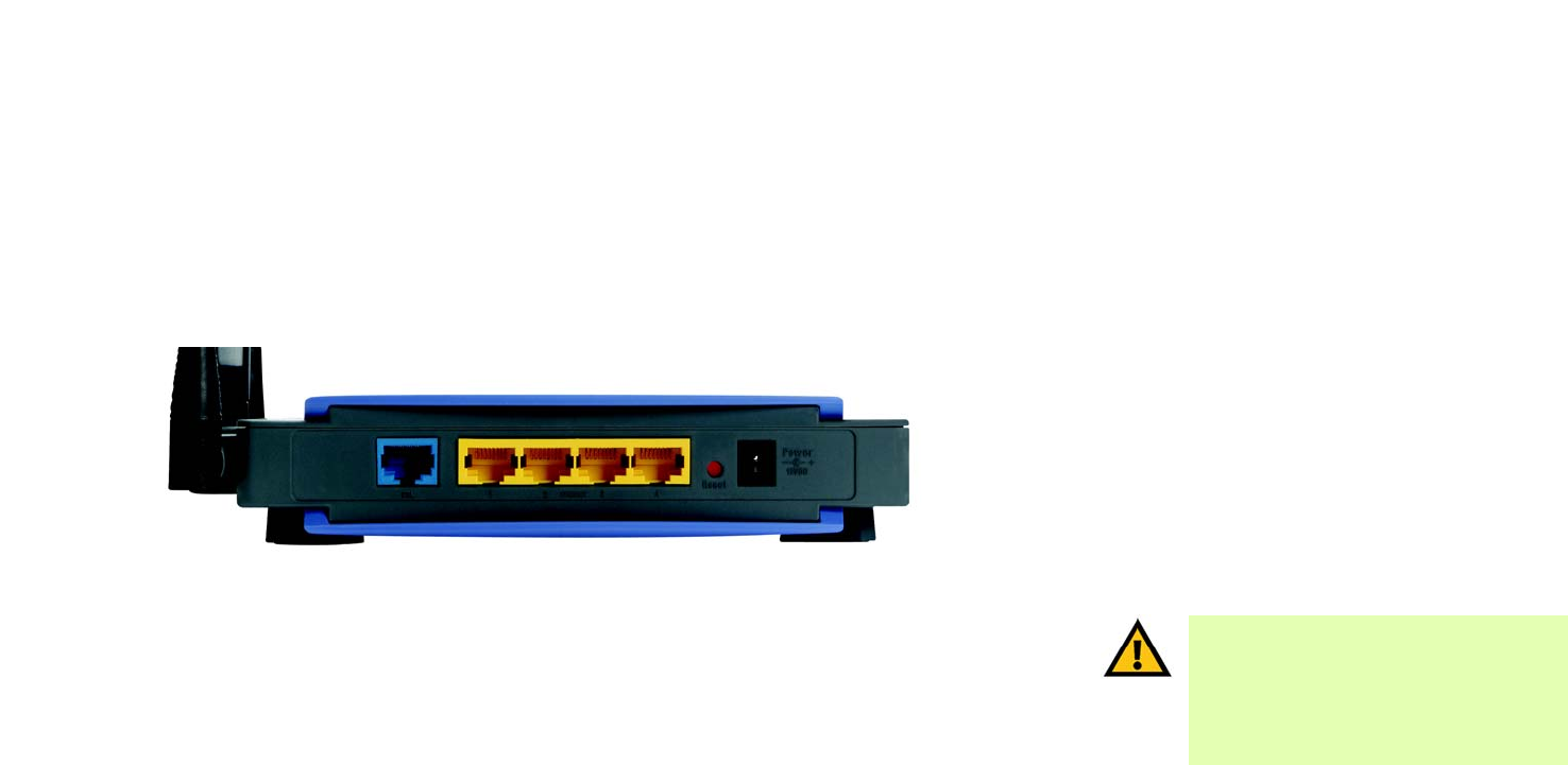
Ports and Reset Button on Back Panel
The Gateway’s ports and Reset button are located on a side panel.
Internet The Internet port connects to the ADSL line. RJ45 and RJ11.
Ethernet (1-4) The Ethernet ports connect to your computers and other network devices.
Reset Button There are two ways to reset the Gateway's factory defaults. Either press the Reset Button,
for approximately five seconds, or restore the defaults from the Factory Defaults screen of
the Administration tab in the Gateway’s Web-based Utility.
Power The Power port is where you will connect the power adapter.
IMPORTANT: Resetting the Gateway to factory
defaults will erase all of your settings
(including Internet connection, wireless, and
other settings) and replace them with the
factory defaults. Do not reset the Gateway if
you want to retain these settings.
Figure 3-1: Ports and Reset Button on Side Panel
* Cable of RJ11 Port should use the line of 26AWG

7
Chapter 3: Getting to Know the Wireless-N ADSL2+ Gateway
LEDs on Front Panel
Wireless-N ADSL2+ Gateway
LEDs on Front Panel
The Gateway's LEDs, which indicate network activity, are located on the front panel.
POWER Green. The POWER LED lights up when the Gateway is powered on.
ETHERNET (1-4) Green. The ETHERNET LED serves two purposes. If the LED is continuously lit, the Gateway
is successfully connected to a device through the Ethernet port. If the LED is flashing, it is an
indication of any network activity.
DSL Green. The DSL LED lights up whenever there is a successful DSL connection. The LED
flashes while the Gateway is establishing the ADSL connection.
INTERNET Green. The INTERNET LED lights up green when an Internet connection to the Internet
Service Provider (ISP) is established. The INTERNET LED lights up red when the connection
to the ISP fails.
WIRELESS Green. The WIRELESS LED lights up whenever there is a successful wireless connection. If
the LED is flashing, the Gateway is actively sending or receiving data to or from one of the
devices on the network.
SECURITY Green. The SECURITY LED lights up when wireless security settings have been set.
Figure 3-2: LEDs on Side Panel
8
Chapter 4: Connecting the Wireless-N ADSL2+ Gateway
Overview
Wireless-N ADSL2+ Gateway
Chapter 4: Connecting the Wireless-N ADSL2+ Gateway
Overview
The installation technician from your ISP should have left the setup information with you after installing your
broadband connection. If not, you can call your ISP to request that data. After you have the setup information you
need for your specific type of Internet connection, you can begin installation and setup of the Gateway.
To use a computer with an Ethernet adapter to configure the Gateway, continue to “Wired Connection to a
Computer.” To use a wireless-equipped computer, continue to “Wireless Connection to a Computer.”
Wired Connection to a Computer
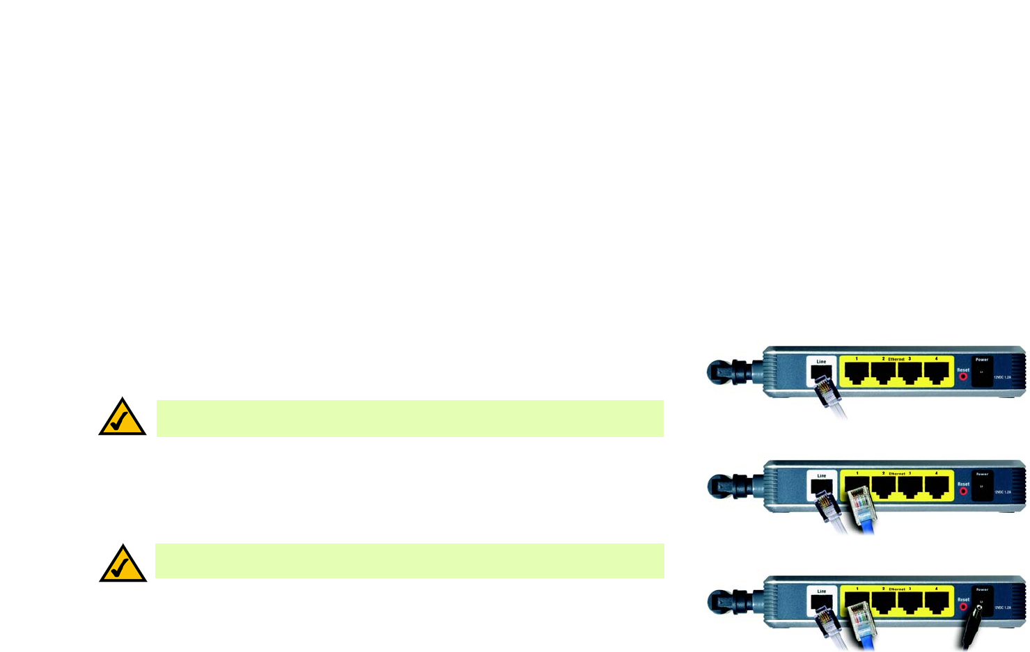
1. Make sure that all of your network’s hardware is powered off, including the Gateway and all computers.
2. Connect a phone cable from the DSL port on the Gateway’s side panel to the wall jack of the ADSL line. A
small device called a microfilter (not included) may be necessary between each phone and wall jack to
prevent interference. Contact your ISP if you have any questions.
3. Connect one end of an Ethernet network cable to one of the Ethernet ports (labeled 1-4) on the back of the
Gateway, and the other end to an Ethernet port on a computer. Repeat this step to connect more computers, a
switch, or other network devices to the Gateway.
4. Connect the power adapter to the Gateway’s Power port, and then plug the power adapter into a power outlet.
The Power LED on the front panel will light up green as soon as the power adapter is connected properly. The
Power LED will flash for a few seconds, and then it will be solidly lit when the self-test is complete. If the LED
flashes for one minute or longer, see “Appendix A: Troubleshooting.”
5. Power on one of your computers that is connected to the Gateway.
Go to “Chapter 5: Configuring the Wireless-N ADSL2+ Gateway.”
NOTE:
A small device called a microfilter (not included) may be necessary between each phone
and wall jack to prevent interference. Contact your ISP if you have any questions.
NOTE: You should always plug the Gateway’s power adapter into a power strip with surge
protection.
Figure 4-2: Connect a PC
Figure 4-1: Connect the ADSL Line
Figure 4-3: Connect the Power
9
Chapter 4: Connecting the Wireless-N ADSL2+ Gateway
Wireless Connection to a Computer
Wireless-N ADSL2+ Gateway
Wireless Connection to a Computer
If you want to use a wireless connection to access the Gateway, follow these instructions:
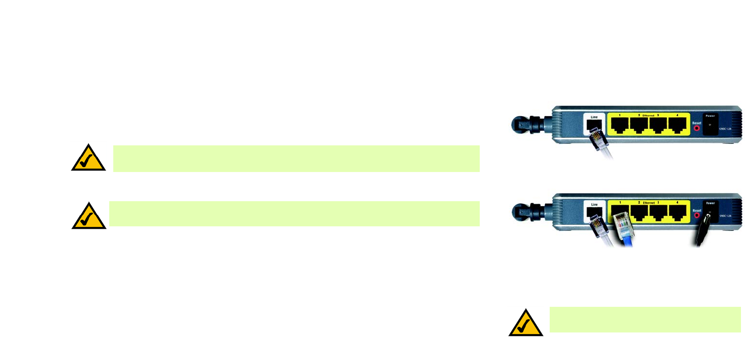
1. Make sure that all of your network’s hardware is powered off, including the Gateway and all computers.
2. Connect a phone cable from the DSL port on the Gateway’s back panel to the wall jack of the ADSL line. A
small device called a microfilter (not included) may be necessary between each phone and wall jack to
prevent interference. Contact your ISP if you have any questions.
3. Connect the power adapter to the Power port, and then plug the power adapter into a power outlet.
The Power LED on the front panel will light up green as soon as the power adapter is connected properly. The
Power LED will flash for a few seconds, and then it will be solidly lit when the self-test is complete. If the LED
flashes for one minute or longer, see “Appendix A: Troubleshooting.”
4. Power on one of the computers on your wireless network(s).
5. For initial access to the Gateway through a wireless connection, make sure the computer’s wireless adapter
has its SSID set to linksys (the Gateway’s default setting), and its wireless security is disabled. After you have
accessed the Gateway, you can change the Gateway and this computer’s adapter settings to match your usual
network settings.
Go to “Chapter 5: Configuring the Wireless-N ADSL2+ Gateway.”
NOTE: You should always change the SSID from
its default, linksys, and enable wireless security.
Figure 4-4: Connect the ADSL Line
Figure 4-5: Connect the Power
NOTE:
A small device called a microfilter (not included) may be necessary between each phone
and wall jack to prevent interference. Contact your ISP if you have any questions.
NOTE: You should always plug the Gateway’s power adapter into a power strip with surge
protection.

10
Chapter 5: Configuring the Wireless-N ADSL2+ Gateway
Overview
Wireless-N ADSL2+ Gateway
Chapter 5: Configuring the Wireless-N ADSL2+ Gateway
Overview
Follow the steps in this chapter and use the Gateway’s Web-based Utility to configure the Gateway. This chapter
will describe each web page in the Utility and each page’s key functions. The utility can be accessed via your web
browser through use of a computer connected to the Gateway. For a basic network setup, most users only have to
use the following screens of the Utility:
• Basic Setup. On the Basic Setup screen, enter the settings provided by your ISP.
• Management. Click the Administration tab and then the Management tab. The Gateway’s default username
and password is admin. To secure the Gateway, change the default username and password.
There are seven main tabs: Setup, Wireless, Security, Access Restrictions, Applications & Gaming, Administration,
and Status. Additional tabs will be available after you click one of the main tabs. Click Help for more information.
Setup
• Basic Setup. Enter the Internet connection and network settings on this screen.
• DDNS. To enable the Gateway’s Dynamic Domain Name System (DDNS) feature, complete the fields on this
screen.
• Advanced Routing. On this screen, you can alter NAT and routing configurations.
Wireless
• Basic Wireless Settings. You can choose your wireless network settings on this screen.
• Wireless Security. Configure your wireless security settings on this screen.
• Wireless MAC Filter. This screen lets you control access to your wireless network.
• Advanced Wireless Settings. On this screen you can access the advanced wireless network settings.
NOTE: For added security, you should change
the username and password through the
Administration tab.
HAVE YOU: Enabled TCP/IP on your
computers? Computers communicate over the
network with this protocol. Refer to Windows
Help for more information on TCP/IP.

11
Chapter 5: Configuring the Wireless-N ADSL2+ Gateway
Overview
Wireless-N ADSL2+ Gateway
Security
• Firewall. Use this screen to enable/disable the firewall, set up filters, and block anonymous Internet requests.
• VPN Passthrough. You can enable or disable Virtual Private Network (VPN) Passthrough on this screen.
Access Restrictions
• Internet Access Policy. This screen allows you to control the Internet usage and traffic on your local network.
Applications & Gaming
• Single Port Range Forwarding. Use this screen to set up common services or applications that require
forwarding on a single port.
• Port Range Forwarding. To set up public services or other specialized Internet applications that require
forwarding on a range of ports, use this screen.
• Port Triggering. To set up triggered ranges and forwarded ranges for Internet applications, click this tab.
• DMZ. To allow one local computer to be exposed to the Internet for use of special-purpose services, use this
screen.
• QoS. Use Quality of Service (QoS) to assign different priority levels to different types of data transmissions.
Administration
• Management. On this screen, alter Gateway access, Simple Network Management Protocol (SNMP), Universal
Plug and Play (UPnP), and wireless management settings.
• Reporting. If you want to view or save activity logs, click this tab.
• Diagnostics. Use this screen to run a Ping test.
• Backup & Restore. On this screen, you can back up or restore the Gateway’s configuration.
• Factory Defaults. If you want to restore the Gateway’s factory default settings, use this screen.
• Firmware Upgrade. Click this tab if you want to upgrade the Gateway’s firmware.
vpn (virtual private network): a security
measure to protect data as it leaves one
network and goes to another over the Internet.

12
Chapter 5: Configuring the Wireless-N ADSL2+ Gateway
How to Access the Web-based Utility
Wireless-N ADSL2+ Gateway
Status
• Gateway. This screen provides status information about the Gateway.
• Local Network. This provides status information about the local network.
• Wireless. This screen provides status information about the wireless network.
• DSL Connection. This screen provides status information about the DSL connection.
How to Access the Web-based Utility
To access the Web-based Utility, launch your web browser, and enter the Gateway’s default IP address,
192.168.1.1, in the Address field. Then press Enter.
A login screen will appear (Windows XP users will see a similar screen). Enter admin (the default user name) in
the User Name field, and enter admin (the default password) in the Password field. Then click the OK button.
The Setup Tab
The Basic Setup Tab
The first screen that appears is the Basic Setup tab. This tab allows you to change the Gateway's general
settings. Change these settings as described here and click the Save Settings button to save your changes, or
click the Cancel Changes button to cancel your changes. Click Help for more information.
Internet Setup
• Internet Connection Type. The Gateway supports six Encapsulation methods: RFC 1483 Bridged, RFC 1483
Routed, IPoA, RFC 2516 PPPoE, RFC 2364 PPPoA, and Bridge Mode Only. Select the appropriate type of
encapsulation from the drop-down menu. Each Basic Setup screen and available features will differ
depending on what type of encapsulation you select.
• VC Settings. You will configure your Virtual Circuit (VC) settings in this section.
• Multiplexing: Select LLC or VC, depending on your ISP.
• QoS Type: Select from the drop-down menu: CBR (Continuous Bit Rate) to specify fixed bandwidth for
voice or data traffic; UBR (Unspecific Bit Rate) for application that are none-time sensitive, such as e-mail;
or VBR (Variable Bite Rate) for bursty traffic and bandwidth-sharing with other applications. Figure 5-1: Basic Setup

13
Chapter 5: Configuring the Wireless-N ADSL2+ Gateway
The Setup Tab
Wireless-N ADSL2+ Gateway
• Pcr Rate: For the Peak Cell Rate, divide the DSL line rate by 424 to get the maximum rate the sender can
send cells. Enter the rate in the field (if required by your service provider).
• Scr Rate: The Sustain Cell Rate sets the average cell rate that can be transmitted. The SCR value is
normally less than the PCR value. Enter the rate in the field (if required by your service provider).
• Autodetect: Select Enable to have the settings automatically entered, or select Disable to enter the
values manually.
• Virtual Circuit: These fields consist of two items: VPI (Virtual Path Identifier) and VCI (Virtual Channel
Identifier). Your ISP will provide the correct settings for these fields.
• DSL Modulation: Select the appropriate mode: MultiMode, T1 .413, G.dmt, G.lite, ADSL2, or ADSL2+.
Contact your ISP if you are not sure which mode to use.
• IP Settings. Follow the instructions in the section for your type of encapsulation.
RFC 1483 Bridged
Dynamic IP
IP Settings. Select Obtain an IP Address Automatically if your ISP says you are connecting through a
dynamic IP address.
Static IP
If you are required to use a permanent (static) IP address to connect to the Internet, then select Use the
following IP Address.
• Internet IP Address. This is the Gateway’s IP address, when seen from the WAN, or the Internet. Your ISP
will provide you with the IP Address you need to specify here.
• Subnet Mask. This is the Gateway’s Subnet Mask. Your ISP will provide you with the Subnet Mask.
• Default Gateway. Your ISP will provide you with the default Gateway Address, which is the ISP server’s IP
address.
• Primary DNS (Required) and Secondary DNS (Optional). Your ISP will provide you with at least one DNS
(Domain Name System) Server IP Address.
Figure 5-2: RFC 1483 Bridged
14
Chapter 5: Configuring the Wireless-N ADSL2+ Gateway
The Setup Tab
Wireless-N ADSL2+ Gateway
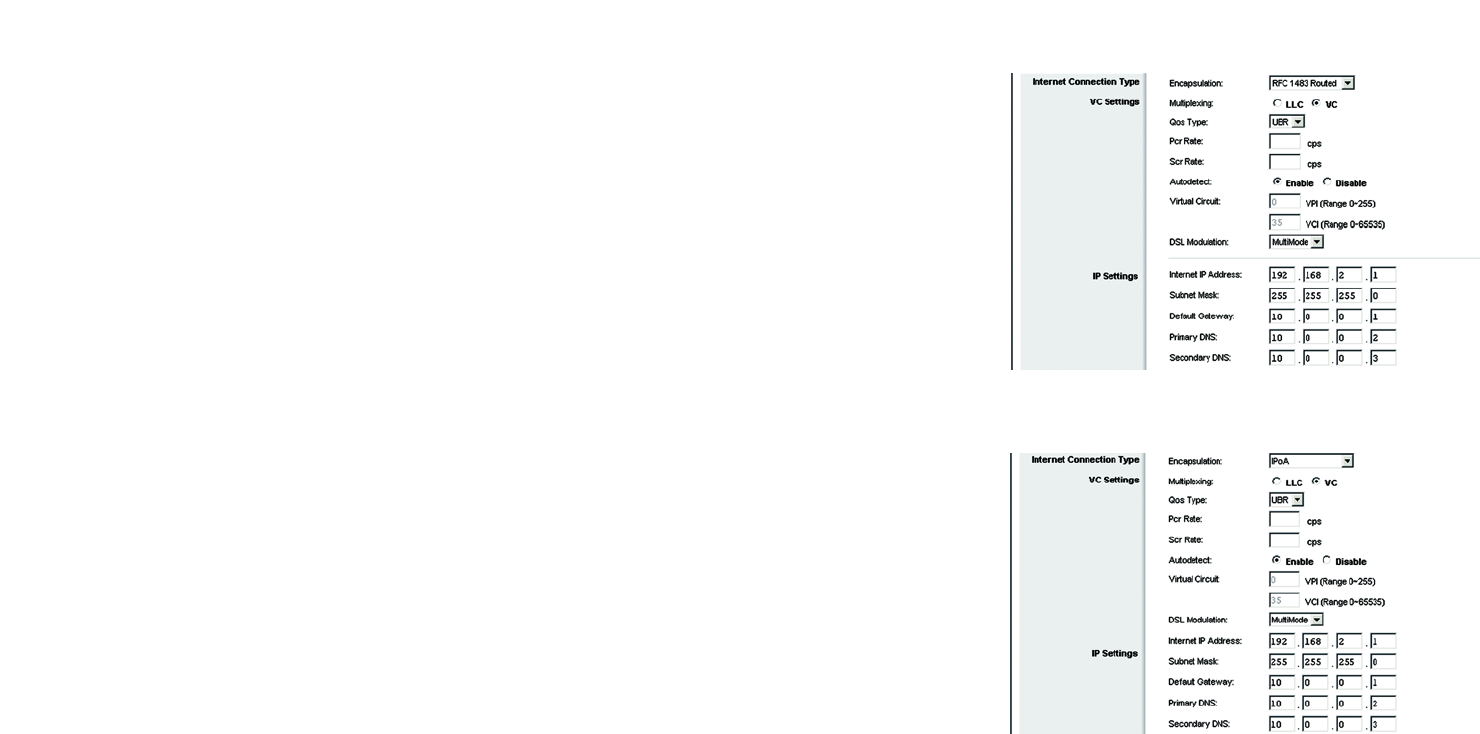
RFC 1483 Routed
If you are required to use RFC 1483 Routed, then select RFC 1483 Routed.
• Internet IP Address. This is the Gateway’s IP address, when seen from the WAN, or the Internet. Your ISP
will provide you with the IP Address you need to specify here.
• Subnet Mask. This is the Gateway’s Subnet Mask. Your ISP will provide you with the Subnet Mask.
• Default Gateway. Your ISP will provide you with the default Gateway Address, which is the ISP server’s IP
address.
• Primary DNS (Required) and Secondary DNS (Optional). Your ISP will provide you with at least one DNS
(Domain Name System) Server IP Address.
IPoA
If you are required to use IPoA (IP over ATM), then select IPoA.
• Internet IP Address. This is the Gateway’s IP address, when seen from the WAN, or the Internet. Your ISP
will provide you with the IP Address you need to specify here.
• Subnet Mask. This is the Gateway’s Subnet Mask. Your ISP will provide you with the Subnet Mask.
• Default Gateway. Your ISP will provide you with the default Gateway Address, which is the ISP server’s IP
address.
• Primary DNS (Required) and Secondary DNS (Optional). Your ISP will provide you with at least one DNS
(Domain Name System) Server IP Address.
Figure 5-3: RFC 1483 Routed
Figure 5-4: IPoA

15
Chapter 5: Configuring the Wireless-N ADSL2+ Gateway
The Setup Tab
Wireless-N ADSL2+ Gateway
RFC 2516 PPPoE
Some DSL-based ISPs use PPPoE (Point-to-Point Protocol over Ethernet) to establish Internet connections. If
you are connected to the Internet through a DSL line, check with your ISP to see if they use PPPoE. If they do,
you will have to enable PPPoE.
• User Name and Password. Enter the User Name and Password provided by your ISP.
• Connect on Demand: Max Idle Time. You can configure the Gateway to disconnect the Internet connection
after it has been inactive for a specified period of time (Max Idle Time). If your Internet connection has
been terminated due to inactivity, Connect on Demand enables the Gateway to automatically re-establish
your connection as soon as you attempt to access the Internet again. To use this option, click the Connect
on Demand radio button. In the Max Idle Time field, enter the number of minutes you want to have
elapsed before your Internet connection terminates.
• Keep Alive: Redial Period. If you select this option, the Gateway will periodically check your Internet
connection. If you are disconnected, then the Gateway will automatically re-establish your connection. To
use this option, click the Keep Alive radio button. In the Redial Period field, specify how often you want
the Gateway to check the Internet connection. The default Redial Period is 30 seconds.
RFC 2364 PPPoA
Some DSL-based ISPs use PPPoA (Point-to-Point Protocol over ATM) to establish Internet connections. If you
are connected to the Internet through a DSL line, check with your ISP to see if they use PPPoA. If they do, you
will have to enable PPPoA.
• User Name and Password. Enter the User Name and Password provided by your ISP.
• Connect on Demand: Max Idle Time. You can configure the Gateway to disconnect the Internet connection
after it has been inactive for a specified period of time (Max Idle Time). If your Internet connection has
been terminated due to inactivity, Connect on Demand enables the Gateway to automatically re-establish
your connection as soon as you attempt to access the Internet again. To use this option, click the Connect
on Demand radio button. In the Max Idle Time field, enter the number of minutes you want to have
elapsed before your Internet connection terminates.
Keep Alive: Redial Period. If you select this option, the Gateway will periodically check your Internet
connection. If you are disconnected, then the Gateway will automatically re-establish your connection. To
use this option, click the Keep Alive radio button. In the Redial Period field, specify how often you want
the Gateway to check the Internet connection. The default Redial Period is 30 seconds.
Figure 5-6: RFC 2364 PPPoA
Figure 5-5: RFC 2516 PPPoE
IMPORTANT: For Connect on Demand to work
correctly, close all Internet applications or the
Gateway may not drop the connection depending
on how often the application tries to get on the
Internet (e.g., chat programs).
16
Chapter 5: Configuring the Wireless-N ADSL2+ Gateway
The Setup Tab
Wireless-N ADSL2+ Gateway
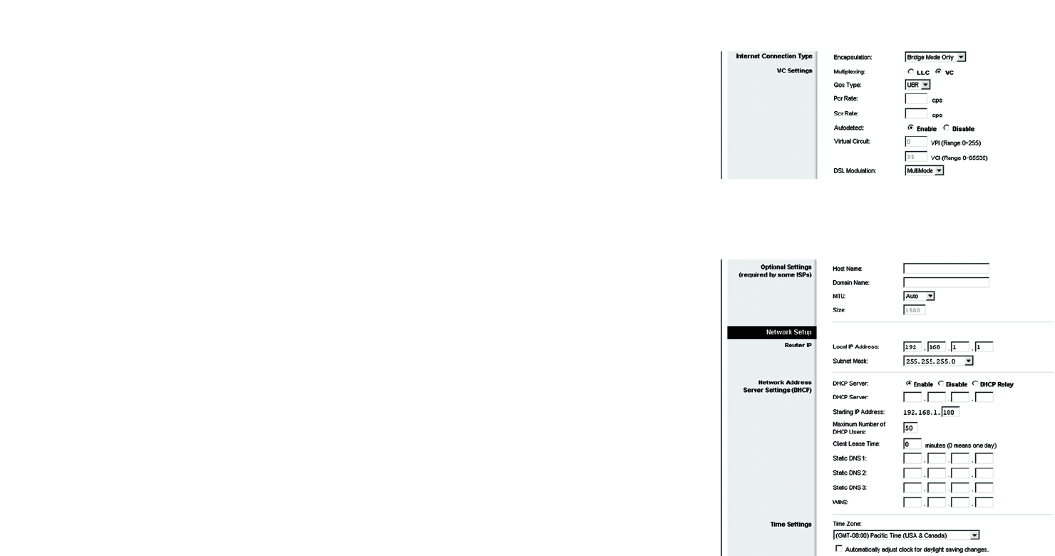
Bridge Mode Only
If you are using your Gateway as a bridge, which makes the Gateway act like a stand-alone modem, select
Bridge Mode Only. All NAT and routing settings are disabled in this mode.
Optional Settings (required by some ISPs)
• Host Name and Domain Name. These fields allow you to supply a host and domain name for the Gateway.
Some ISPs require these names as identification. You may have to check with your ISP to see if your
broadband Internet service has been configured with a host and domain name. In most cases, you can leave
these fields blank.
• MTU and Size. The MTU (Maximum Transmission Unit) setting specifies the largest packet size permitted for
network transmission. Select Manual and enter the value desired in the Size field. It is recommended that
you leave this value in the 1200 to 1500 range. By default, MTU is configured automatically.
Network Setup
• Router IP. The values for the Gateway’s Local IP Address and Subnet Mask are shown here. In most cases,
keeping the default values will work.
• Local IP Address. The default value is 192.168.1.1.
• Subnet Mask. The default value is 255.255.255.0.
• Network Address Server Settings (DHCP). Configure the Gateway’s Dynamic Host Configuration Protocol
(DHCP) settings in this section.
• DHCP Server. A Dynamic Host Configuration Protocol (DHCP) server automatically assigns an IP address to
each computer on your network for you. Unless you already have one, it is highly recommended that you
leave the Gateway enabled as a DHCP server. You can also use the Gateway in DHCP Relay mode. (This
setting is not available for all Encapsulation types.)
• DHCP Server. If you enable the DHCP Relay mode for the DHCP Server setting, enter the IP address for the
DHCP relay server in the fields provided. (This setting is not available for all Encapsulation types.)
• Starting IP Address. Enter a value for the DHCP server to start with when issuing IP addresses. This value
must be 192.168.1.2 or greater, because the default IP address for the Gateway is 192.168.1.1.
• Maximum Number of DHCP Users. Enter the maximum number of users/clients that can obtain an IP
address. The number will vary depending on the starting IP address entered.
Figure 5-8: Optional Settings
Figure 5-7: Bridge Mode Only

17
Chapter 5: Configuring the Wireless-N ADSL2+ Gateway
The Setup Tab
Wireless-N ADSL2+ Gateway
• Client Lease Time. The Client Lease Time is the amount of time a computer will be allowed connection to
the Gateway with its current dynamic IP address. Enter the amount of time, in minutes, that the computer
will be “leased” this dynamic IP address.
• Static DNS 1-3. The Domain Name System (DNS) is how the Internet translates domain or website names
into Internet addresses or URLs. Your ISP will provide you with at least one DNS Server IP Address. You
can enter up to three DNS Server IP Addresses here. The Gateway will use these for quicker access to
functioning DNS servers.
• WINS. The Windows Internet Naming Service (WINS) converts NetBIOS names to IP addresses. If you use a
WINS server, enter that server’s IP address here. Otherwise, leave this field blank.
• Time Setting. Select the appropriate time zone for the Gateway’s location. If desired, check the
Automatically adjust clock for daylight saving changes checkbox.
When finished making your changes on this tab, click the Save Settings button to save these changes, or click
the Cancel Changes button to undo your changes. Click Help for more information.
18
Chapter 5: Configuring the Wireless-N ADSL2+ Gateway
The Setup Tab
Wireless-N ADSL2+ Gateway
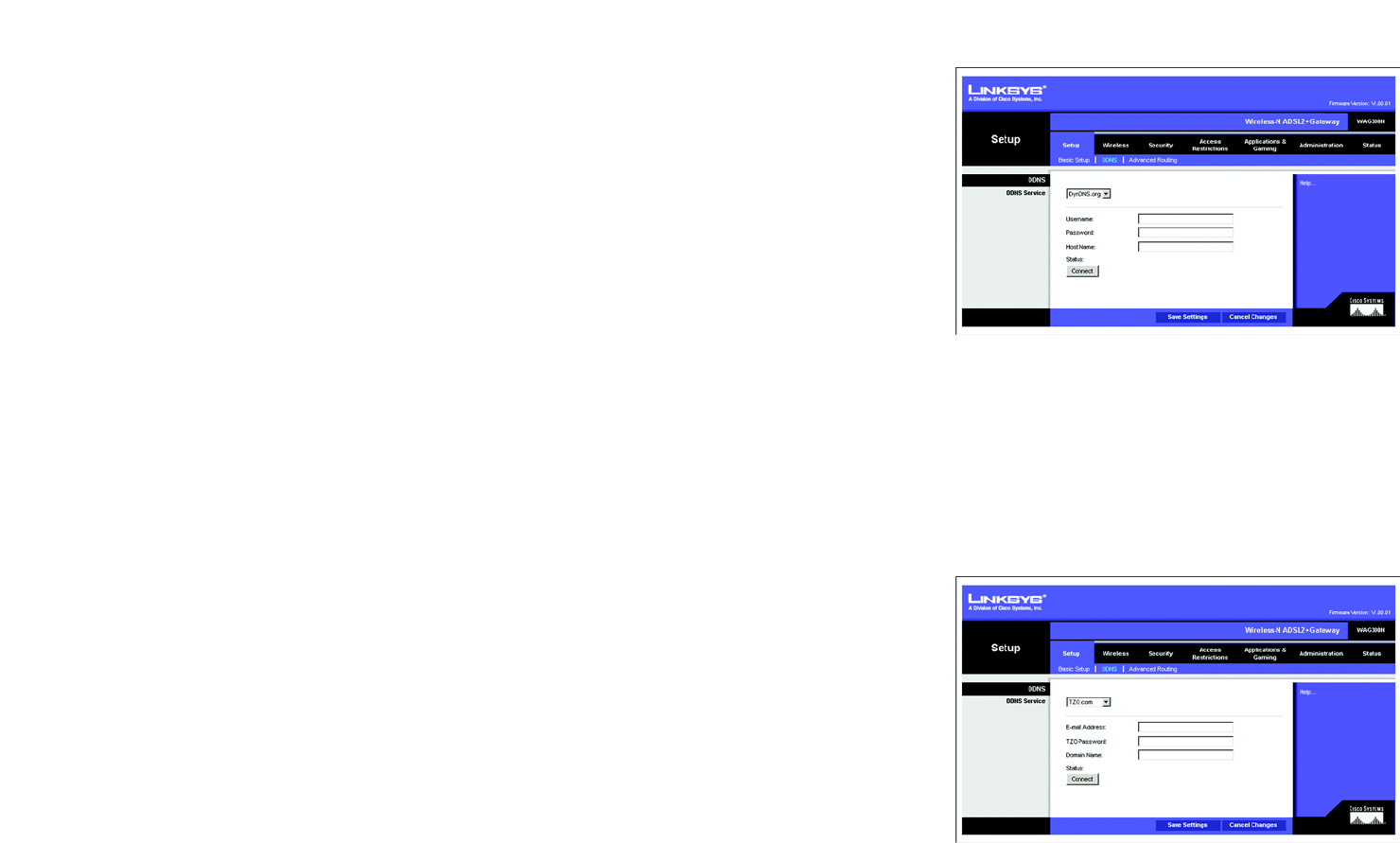
The DDNS Tab
The Gateway offers a Dynamic Domain Name System (DDNS) feature. DDNS lets you assign a fixed host and
domain name to a dynamic Internet IP address. It is useful when you are hosting your own website, FTP server, or
other server behind the Gateway.
Before you can use this feature, you need to sign up for DDNS service at DynDNS.org or TZO.com.
DDNS
DDNS Service. If your DDNS service is provided by DynDNS.org, then select DynDNS.org from the drop-down
menu. If your DDNS service is provided by TZO.com, then select TZO.com from the drop-down menu. To disable
DDNS Service, select Disabled.
DynDNS.org
• User Name, Password, and Host Name. Enter the User Name, Password, and Host Name of the account you
set up with DynDNS.org.
• Status. The status of the DDNS service connection is displayed here.
• Connect. Click the Connect button to start the DDNS service connection.
TZO.com
• E-mail Address, Password, and Domain Name. Enter the E-mail Address, Password, and Domain Name of the
account you set up with TZO.
• Status. The status of the DDNS service connection is displayed here.
• Connect. Click the Connect button to start the DDNS service connection.
When finished making your changes on this tab, click the Save Settings button to save these changes, or click
the Cancel Changes button to undo your changes. Click Help for more information.
Figure 5-9: DDNS - DynDNS.org
Figure 5-10: DDNS - TZO.com
19
Chapter 5: Configuring the Wireless-N ADSL2+ Gateway
The Setup Tab
Wireless-N ADSL2+ Gateway
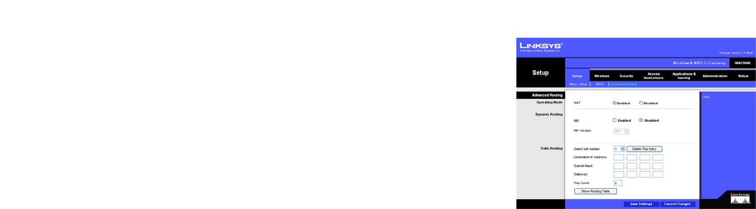
The Advanced Routing Tab
The Advanced Routing screen allows you to configure the NAT, dynamic routing, and static routing settings.
Advanced Routing
• Operating Mode. In this section, you will configure the Gateway’s general routing settings.
• NAT. NAT is a security feature that is enabled by default. It enables the Gateway to translate IP addresses
of your local area network to a different IP address for the Internet. To disable NAT, click the Disabled
radio button.
• Dynamic Routing. With Dynamic Routing you can enable the Gateway to automatically adjust to physical
changes in the network’s layout. Using RIP, the Gateway determines the network packets’ route based on the
fewest number of hops between the source and the destination. The RIP protocol regularly broadcasts routing
information to other Gateways on the network.
• RIP. If you have multiple routers, you may want to use the Routing Information Protocol (RIP) so the routers
can exchange routing information with each other. To use RIP, select the Enabled radio button. Otherwise,
keep the default, Disabled.
• RIP Version. Select the protocol version you want, RIP1 or RIPv2.
• Static Routing. If the Gateway is connected to more than one network, it may be necessary to set up a static
route between them. A static route is a pre-determined pathway that network information must travel to
reach a specific host or network. To create a static route, change the following settings:
• Select set number. Select the number of the static route from the drop-down menu. The Gateway
supports up to 20 static route entries. If you need to delete a route, then select the entry and click the
Delete This Entry button.
• Destination IP Address. The Destination IP Address is the address of the remote network or host to which
you want to assign a static route. Enter the IP address of the host for which you wish to create a static
route. If you are building a route to an entire network, be sure that the network portion of the IP address is
set to 0.
• Subnet Mask. Enter the Subnet Mask (also known as the Network Mask), which determines which portion
of an IP address is the network portion, and which portion is the host portion.
• Gateway. Enter the IP address of the gateway device that allows for contact between the Gateway and the
remote network or host.
Figure 5-11: Advanced Routing
20
Chapter 5: Configuring the Wireless-N ADSL2+ Gateway
The Setup Tab
Wireless-N ADSL2+ Gateway
• Hop Count. Hop Count is the number of hops to each node until the destination is reached (16 hops
maximum). Enter the Hop Count in the field provided.
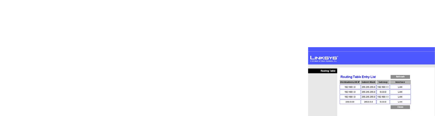
• Show Routing Table. Click the Show Routing Table button to open a screen displaying how data is routed
through your local network. For each route, the Destination LAN IP address, Subnet Mask, Gateway, and
Interface are displayed. Click the Refresh button to update the information. Click the Close button to return to
the previous screen.
When finished making your changes on this tab, click the Save Settings button to save these changes, or click
the Cancel Changes button to undo your changes. Click Help for more information.
Figure 5-12: Routing Table

21
Chapter 5: Configuring the Wireless-N ADSL2+ Gateway
The Wireless Tab
Wireless-N ADSL2+ Gateway
The Wireless Tab
The Basic Wireless Settings Tab
This screen allows you to choose your wireless network mode and wireless security.
Wireless Network
• Network Mode. If you have 802.11g and 802.11b devices in your network, then keep the default setting,
Mixed. If you have only Wireless-G devices, select Wireless-G Only. If you have only Wireless-B devices,
select Wireless-B Only. If you have only Wireless-N devices, select Wireless-N Only. If you want to disable
wireless networking, select Disable.
• Network Name (SSID). Enter the name for your wireless network into the field. The SSID is the network name
shared among all devices in a wireless network. It must be identical for all devices in the wireless network. It
is case-sensitive and must not exceed 32 alphanumeric characters, which may be any keyboard character.
Linksys recommends that you change the default SSID (linksys) to a unique name of your choice.
• Radio Band. For best performance in a network using Wireless-N, Wireless-G and Wireless-B devices, keep
the default, Wide - 40MHz Channel. For Wireless-G and Wireless-B networking only, select Standard -
20MHz Channel.
• Wide Channel. If you selected Wide - 40MHz Channel for the Radio Band setting, then this setting will be
available for your primary Wireless-N channel. Select any channel from the drop-down menu.
• Standard Channel. Select the channel for Wireless-N, Wireless-G, and Wireless-B networking. If you selected
Wide – 40MHz Channel for the Radio Band setting, then the Standard Channel will be a secondary channel for
Wireless-N. If you are not sure which channel to select, do not make any changes.
• Wireless SSID Broadcast. When wireless computers or clients survey the local area for wireless networks to
associate with, they will detect the SSID broadcast by the Gateway. To broadcast the Gateway's SSID, keep
the default setting, Enable. If you do not want to broadcast the Gateway's SSID, then select Disable.
When finished making your changes on this tab, click the Save Settings button to save these changes, or click
the Cancel Changes button to undo your changes. Click Help for more information.
Figure 5-13: Basic Wireless Settings
NOTE: If you select Wide - 40MHz Channel for the
Radio Band setting, then Wireless-N can use two
channels: a primary one (Wide Channel) and a
secondary one (Standard Channel). This will
enhance Wireless-N performance.
22
Chapter 5: Configuring the Wireless-N ADSL2+ Gateway
The Wireless Tab
Wireless-N ADSL2+ Gateway
The Wireless Security Tab
The Wireless Security settings configure the security of your wireless network. There are six wireless security
options supported by the Gateway: WPA-Personal, WPA2-Personal, WPA-Enterprise, WPA2-Enterprise, RADIUS,
and WEP. WPA stands for Pre-Shared Key, which is a security standard stronger than WEP (Wired Equivalent
Privacy) encryption. WPA2 is a more advanced, more secure version of WPA. WPA-Enterprise, WPA2-Enterprise,
and RADIUS use a RADIUS (Remote Authentication Dial-In User Service) server for authentication. These are
briefly discussed here. For detailed instructions on configuring wireless security for the Gateway, turn to
“Appendix B: Wireless Security.”
If you want to disable wireless security, select Disable from the drop-down menu for Security Mode.
• Security Mode. Select the mode you want your network to use, WPA-Personal, WPA2-Personal,
WPA-Enterprise, WPA2-Enterprise, RADIUS, or WEP. If you have devices using WPA-Personal and WPA2-
Personal, select WPA2-Personal.
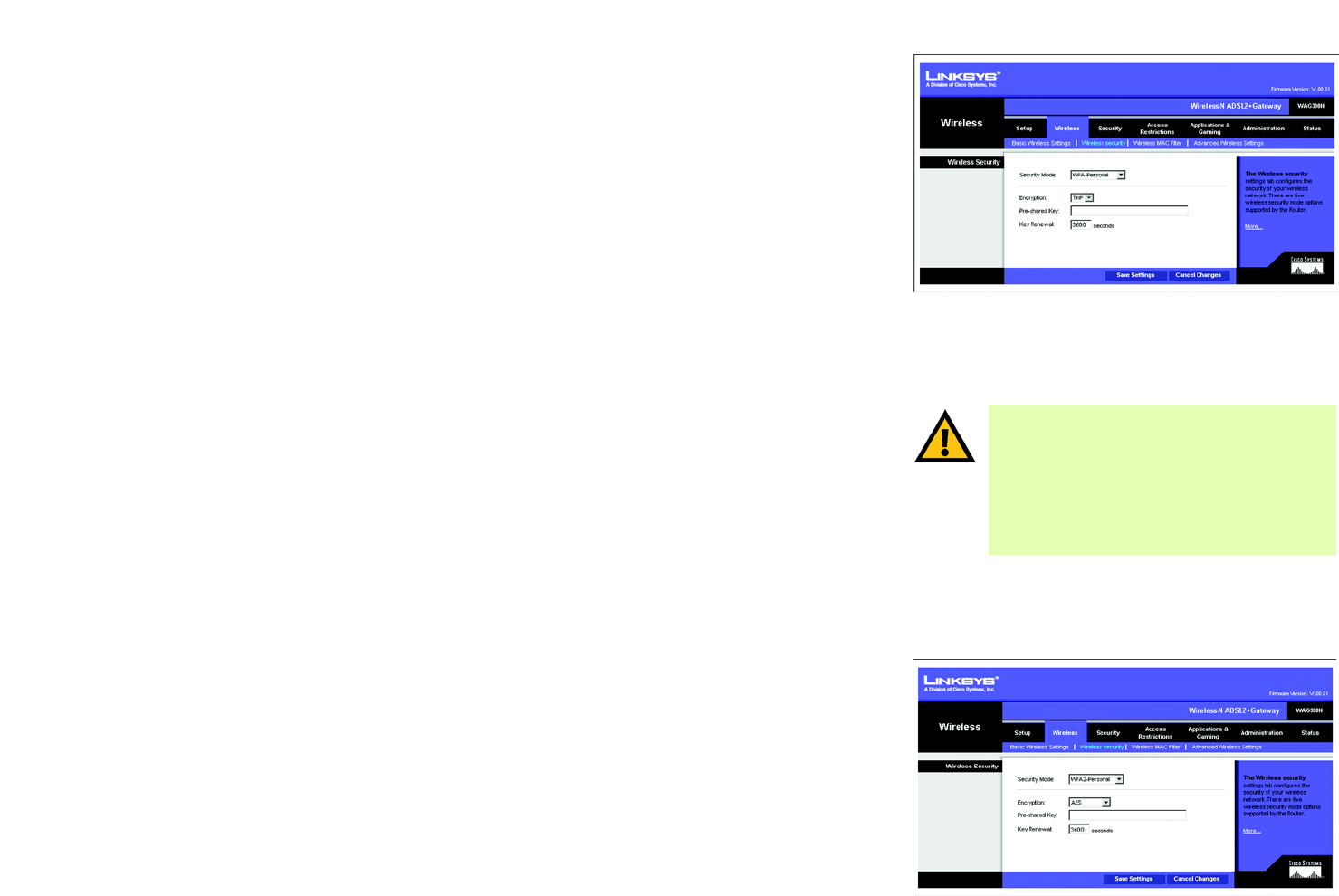
WPA-Personal
• Encryption. Select the method you want to use, TKIP or AES. (AES is a stronger encryption method than TKIP.)
• Pre-shared Key. Enter the key shared by the Gateway and your other network devices. It must have
8 to 63 characters.
• Key Renewal. Enter the Key Renewal period, which tells the Gateway how often it should change the dynamic
encryption keys.
When you have finished making changes to this screen, click the Save Settings button to save the changes, or
click the Cancel Changes button to undo your changes. Click Help for more information.
WPA2-Personal
• Encryption. Select the method you want to use, AES or TKIP or AES.
• Pre-shared Key. Enter the key shared by the Gateway and your other network devices. It must have
8 to 63 characters.
• Key Renewal. Enter the Key Renewal period, which tells the Gateway how often it should change the dynamic
encryption keys.
When you have finished making changes to this screen, click the Save Settings button to save the changes, or
click the Cancel Changes button to undo your changes. Click Help for more information. Figure 5-15: Wireless Security - WPA2-Personal
Figure 5-14: Wireless Security - WPA-Personal
IMPORTANT: If you are using wireless security,
always remember that each device in your
wireless network MUST use the same wireless
security method and shared key, or else the
network will not function correctly. If you have
devices using WPA-Personal and WPA2-Personal,
you should use WPA2-Personal.
23
Chapter 5: Configuring the Wireless-N ADSL2+ Gateway
The Wireless Tab
Wireless-N ADSL2+ Gateway
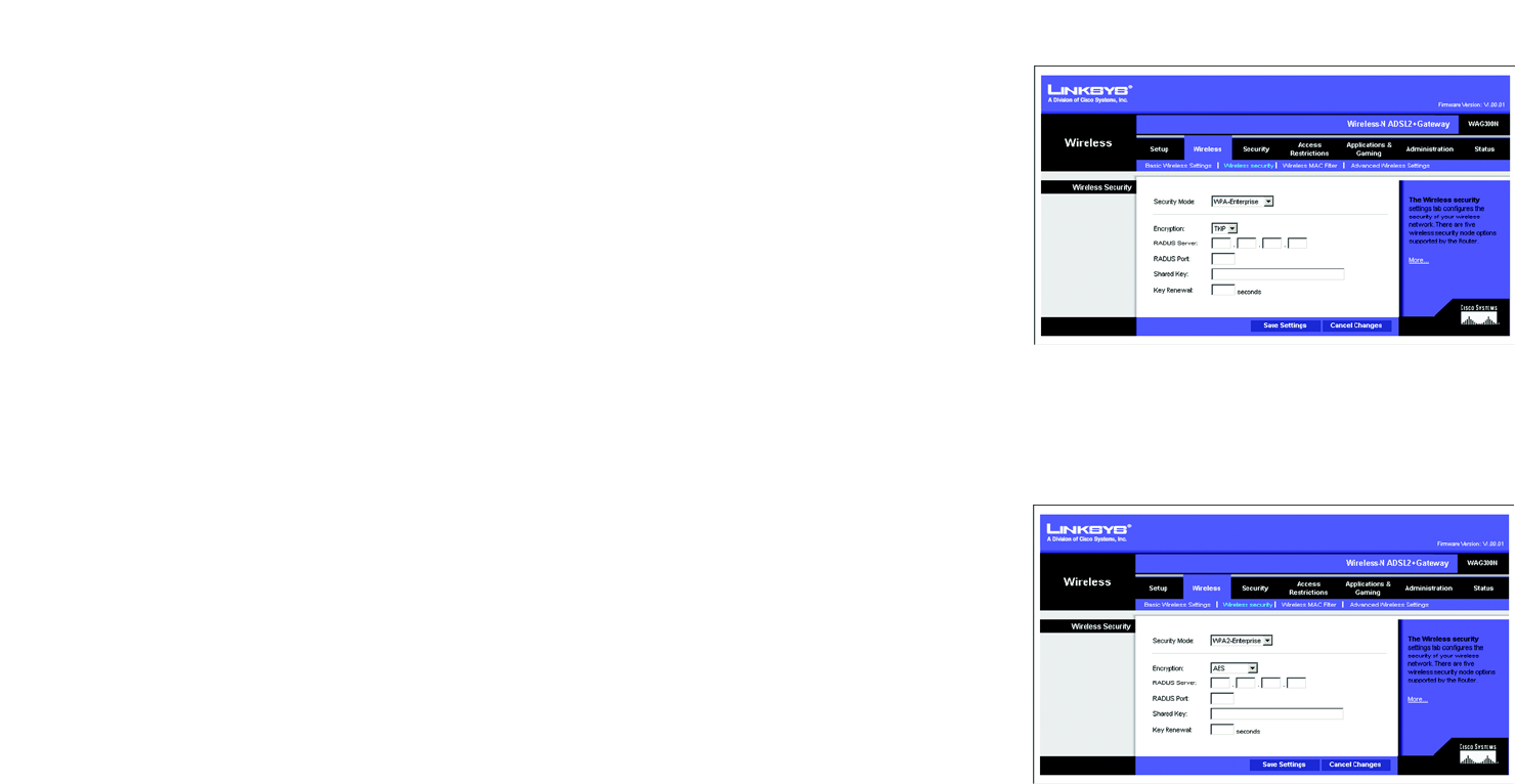
WPA-Enterprise
WPA-Enterprise features WPA used with a RADIUS server. (This method should only be used when the Gateway is
connected to a RADIUS server.)
• Encryption. Select the method you want to use, TKIP or AES. (AES is a stronger encryption method than TKIP.)
• RADIUS Server. Enter the IP address of the RADIUS server.
• RADIUS Port. Enter the port number of the RADIUS server.
• Shared Key. Enter the key shared between the Gateway and its RADIUS server.
• Key Renewal. Enter the Key Renewal period, which tells the Gateway how often it should change the dynamic
encryption keys.
When finished making your changes on this tab, click the Save Settings button to save these changes, or click
the Cancel Changes button to undo your changes. Click Help for more information.
WPA2-Enterprise
WPA2-Enterprise features WPA2 used with a RADIUS server. (This method should only be used when the Gateway
is connected to a RADIUS server.)
• Encryption. Select the method you want to use, AES or TKIP or AES.
• RADIUS Server. Enter the IP address of the RADIUS server.
• RADIUS Port. Enter the port number of the RADIUS server.
• Shared Key. Enter the key shared between the Gateway and its RADIUS server.
• Key Renewal. Enter the Key Renewal period, which tells the Gateway how often it should change the dynamic
encryption keys.
When finished making your changes on this tab, click the Save Settings button to save these changes, or click
the Cancel Changes button to undo your changes. Click Help for more information.
Figure 5-16: Wireless Security - WPA-Enterprise
Figure 5-17: Wireless Security - WPA2-Enterprise
24
Chapter 5: Configuring the Wireless-N ADSL2+ Gateway
The Wireless Tab
Wireless-N ADSL2+ Gateway
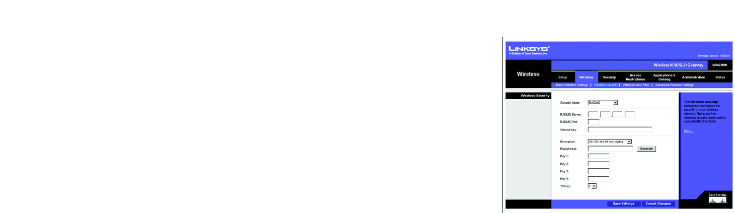
RADIUS
This option features WEP used in coordination with a RADIUS server. (This should only be used when a RADIUS
server is connected to the Gateway.)
• RADIUS Server. Enter the IP address of the RADIUS server.
• RADIUS Port. Enter the port number of the RADIUS server.
• Shared Key. Enter the key shared between the Gateway and its RADIUS server.
• Encryption. Select the appropriate level of encryption, 40/64-bit (10 hex digits) or 104/128-bit (26 hex
digits). A higher level of encryption is more secure.
• Passphrase. Instead of manually entering WEP keys, you can enter a Passphrase. It is case-sensitive and
should not be longer than 32 alphanumeric characters. (This Passphrase function is compatible with Linksys
wireless products only and cannot be used with Windows XP Zero Configuration. If you want to communicate
with non-Linksys wireless products or Windows XP Zero Configuration, make a note of the WEP keys
generated, and enter the appropriate one manually in the wireless computer or client.) If you want to use a
Passphrase, then enter it in the Passphrase field and click the Generate button.
• Keys 1-4. If you are not using a Passphrase, then manually enter a set of values. (Do not leave a key field
blank, and do not enter all zeroes; they are not valid key values.) If you are using 40/64-bit WEP encryption,
the key must be exactly 10 hexadecimal characters in length. If you are using 104/128-bit WEP encryption,
the key must be exactly 26 hexadecimal characters in length. Valid hexadecimal characters are “0”-“9” and
“A”-“F”.
• TX Key. To indicate which WEP key to use, select a default Transmit (TX) Key number.
When you have finished making changes to this screen, click the Save Settings button to save the changes, or
click the Cancel Changes button to undo your changes. For more information, click Help.
Figure 5-18: Wireless Security - RADIUS
25
Chapter 5: Configuring the Wireless-N ADSL2+ Gateway
The Wireless Tab
Wireless-N ADSL2+ Gateway
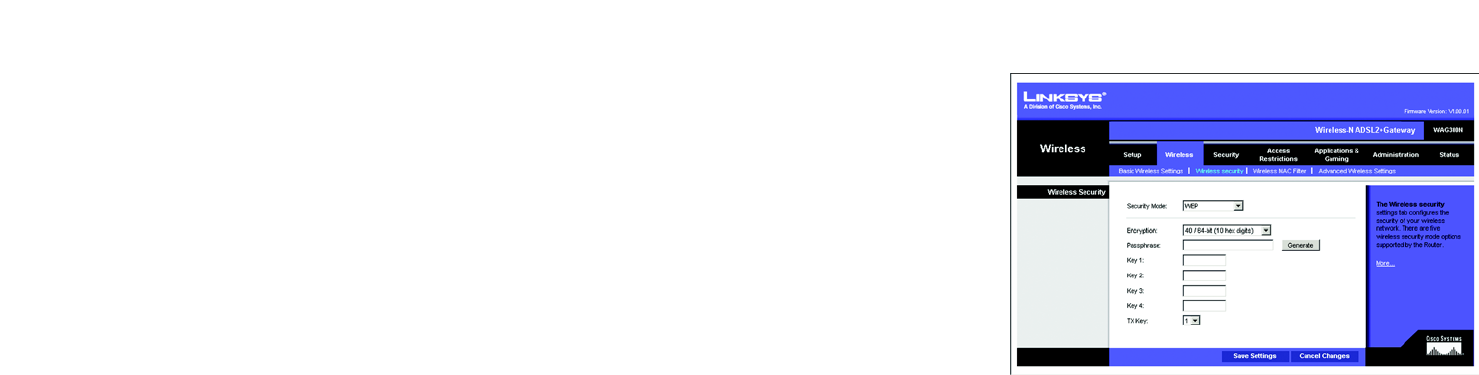
WEP
• Encryption. Select the appropriate level of encryption, 40/64-bit (10 hex digits) or 104/128-bit (26 hex
digits). A higher level of encryption is more secure.
• Passphrase. Instead of manually entering WEP keys, you can enter a Passphrase. It is case-sensitive and
should not be longer than 32 alphanumeric characters. (This Passphrase function is compatible with Linksys
wireless products only and cannot be used with Windows XP Zero Configuration. If you want to communicate
with non-Linksys wireless products or Windows XP Zero Configuration, make a note of the WEP keys
generated, and enter the appropriate one manually in the wireless computer or client.) If you want to use a
Passphrase, then enter it in the Passphrase field and click the Generate button.
• Keys 1-4. If you are not using a Passphrase, then manually enter a set of values. (Do not leave a key field
blank, and do not enter all zeroes; they are not valid key values.) If you are using 40/64-bit WEP encryption,
the key must be exactly 10 hexadecimal characters in length. If you are using 104/128-bit WEP encryption,
the key must be exactly 26 hexadecimal characters in length. Valid hexadecimal characters are “0”-“9” and
“A”-“F”.
• TX Key. To indicate which WEP key to use, select a default Transmit (TX) Key number.
When finished making your changes on this tab, click the Save Settings button to save these changes, or click
the Cancel Changes button to undo your changes. Click Help for more information.
Figure 5-19: Wireless Security - WEP
26
Chapter 5: Configuring the Wireless-N ADSL2+ Gateway
The Wireless Tab
Wireless-N ADSL2+ Gateway
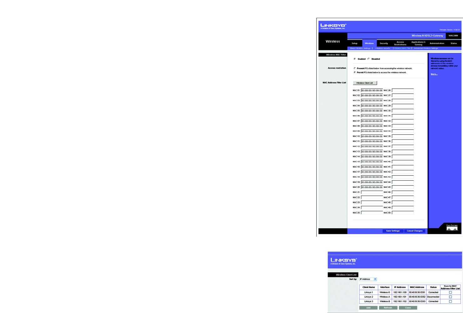
The Wireless MAC Filter Tab
Wireless access can be filtered by using the MAC addresses of the wireless devices transmitting within your
network’s radius.
Wireless MAC Filter
To filter wireless users by MAC Address, either permitting or blocking access, click Enabled. If you do not wish to
filter users by MAC Address, select Disabled.
Access Restrictions
• Prevent. Click this button to block wireless access from the devices listed on this screen.
• Permit. Click this button to allow wireless access by the devices listed on this screen.
MAC Address Filter List
Click the Wireless Client List button to display the Wireless Client List. It shows computers and other devices on
the wireless network. The list can be sorted by Client Name, Interface, IP Address, MAC Address, and Status. Click
the Save to MAC Address Filter List checkbox for any device you want to add to the MAC Address Filter List.
Then click the Add button. To retrieve the most up-to-date information, click the Refresh button. To exit this
screen and return to the Wireless MAC Filter screen, click the Close button.
MAC 01-50. Enter the MAC addresses of the devices whose wireless access you want to block or allow.
When finished making your changes on this tab, click the Save Settings button to save these changes, or click
the Cancel Changes button to undo your changes. Click Help for more information.
Figure 5-20: Wireless MAC Filter
Figure 5-21: Wireless Client List
27
Chapter 5: Configuring the Wireless-N ADSL2+ Gateway
The Wireless Tab
Wireless-N ADSL2+ Gateway
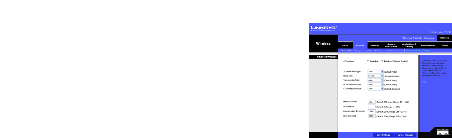
The Advanced Wireless Settings Tab
This tab is used to set up the Gateway’s advanced wireless functions. These settings should only be adjusted by
an expert administrator as incorrect settings can reduce wireless performance.
Advanced Wireless
• AP Isolation. This isolates all wireless clients and wireless devices on your network from each other. Wireless
devices will be able to communicate with the Gateway but not with each other. To use this function, click
Enabled. AP Isolation is disabled by default.
• Authentication Type. The default is set to Auto, which allows either Open System or Shared Key
authentication to be used. Select Shared Key if you only want to use Shared Key authentication (the sender
and recipient use a WEP key for authentication).
• Basic Rate. The Basic Rate setting is not actually one rate of transmission but a series of rates at which the
Gateway can transmit. The Gateway will advertise its Basic Rate to the other wireless devices in your
network, so they know which rates will be used. The Gateway will also advertise that it will automatically
select the best rate for transmission. The default setting is Default, when the Gateway can transmit at all
standard wireless rates (1-2Mbps, 5.5Mbps, 11Mbps, 18Mbps, and 24Mbps). Other options are 1-2Mbps, for
use with older wireless technology, and All, when the Gateway can transmit at all wireless rates.
• Transmission Rate. The rate of data transmission should be set depending on the speed of your wireless
network. You can select from a range of transmission speeds, or you can select Auto to have the Gateway
automatically use the fastest possible data rate and enable the Auto-Fallback feature. Auto-Fallback will
negotiate the best possible connection speed between the Gateway and a wireless client. The default setting
is Auto.
• N Transmission Rate. The rate of data transmission should be set depending on the speed of your Wireless-N
networking. You can select from a range of transmission speeds, or you can select Auto to have the Gateway
automatically use the fastest possible data rate and enable the Auto-Fallback feature. Auto-Fallback will
negotiate the best possible connection speed between the Gateway and a wireless client. The default setting
is Auto.
• CTS Protection Mode. CTS (Clear-To-Send) Protection Mode’s default setting is Auto. The Gateway will
automatically use CTS Protection Mode when your Wireless-N and Wireless-G products are experiencing
severe problems and are not able to transmit to the Gateway in an environment with heavy 802.11b traffic.
This function boosts the Gateway’s ability to catch all Wireless-N and Wireless-G transmissions but will
severely decrease performance.
Figure 5-22: Advanced Wireless Settings

28
Chapter 5: Configuring the Wireless-N ADSL2+ Gateway
The Wireless Tab
Wireless-N ADSL2+ Gateway
• Beacon Interval. Enter a value between 20-1000 milliseconds. The Beacon Interval value indicates the
frequency interval of the beacon. A beacon is a packet broadcast by the Gateway to synchronize the wireless
network. The default value is 100.
• DTIM Interval. This value, between 1 and 255, indicates the interval of the Delivery Traffic Indication Message
(DTIM). A DTIM field is a countdown field informing clients of the next window for listening to broadcast and
multicast messages. When the Gateway has buffered broadcast or multicast messages for associated clients,
it sends the next DTIM with a DTIM Interval value. Its clients hear the beacons and awaken to receive the
broadcast and multicast messages. The default value is 1.
• Fragmentation Threshold. This value specifies the maximum size for a packet before data is fragmented into
multiple packets. If you experience a high packet error rate, you may slightly increase the Fragmentation
Threshold. Setting the Fragmentation Threshold too low may result in poor network performance. Only minor
reduction of the default value is recommended. In most cases, it should remain at its default value of 2346.
• RTS Threshold. Should you encounter inconsistent data flow, only minor reduction of the default value, 2346,
is recommended. If a network packet is smaller than the preset RTS threshold size, the RTS/CTS mechanism
will not be enabled. The Gateway sends Request to Send (RTS) frames to a particular receiving station and
negotiates the sending of a data frame. After receiving an RTS, the wireless station responds with a Clear to
Send (CTS) frame to acknowledge the right to begin transmission. In most cases, keep its default value of
2346.
When finished making your changes on this tab, click the Save Settings button to save these changes, or click
the Cancel Changes button to undo your changes. Click Help for more information.
29
Chapter 5: Configuring the Wireless-N ADSL2+ Gateway
The Security Tab
Wireless-N ADSL2+ Gateway
The Security Tab
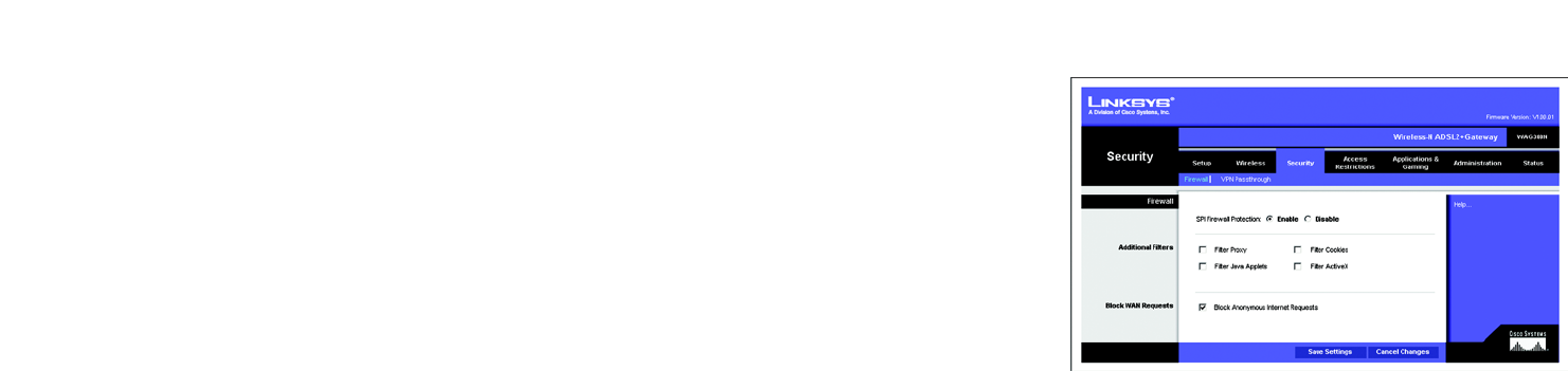
The Firewall Tab
You can enable or disable the firewall, select filters to block specific Internet data types, and block anonymous
Internet requests. Use these features to enhance the security of your network.
Firewall
• SPI Firewall Protection. The Stateful Packet Inspection (SPI) firewall feature enhances the security of your
network. To use this feature, click Enable. If you do not want to use the firewall, click Disable.
Additional Filters
• Filter Proxy. Use of WAN proxy servers may compromise the Gateway's security. Denying Filter Proxy will
disable access to any WAN proxy servers. To enable proxy filtering, click the checkbox.
• Filter Cookies. A cookie is data stored on your computer and used by Internet sites when you interact with
them. To enable cookie filtering, click the checkbox.
• Filter Java Applets. Java is a programming language for websites. If you deny Java Applets, you run the risk
of not having access to Internet sites created using this programming language. To enable Java Applet
filtering, click the checkbox.
• Filter ActiveX. ActiveX is a programming language for websites. If you deny ActiveX, you run the risk of not
having access to Internet sites created using this programming language. To enable ActiveX filtering, click the
checkbox.
Block WAN Requests
• Block Anonymous Internet Requests. This keeps your network from being “pinged” or detected and
reinforces your network security by hiding your network ports, so it is more difficult for intruders to discover
your network. Select Block Anonymous Internet Requests to block anonymous Internet requests or de-
select it to allow anonymous Internet requests.
When finished making your changes on this tab, click the Save Settings button to save these changes, or click
the Cancel Changes button to undo your changes. Click Help for more information.
Figure 5-23: Firewall

30
Chapter 5: Configuring the Wireless-N ADSL2+ Gateway
The Security Tab
Wireless-N ADSL2+ Gateway
The VPN Passthrough Tab
Virtual Private Networking (VPN) is a security measure that basically creates a secure connection between two
remote locations. Configure these settings so the Gateway will permit VPN tunnels to pass through.
VPN Passthrough
• IPSec Passthrough. Internet Protocol Security (IPSec) is a suite of protocols used to implement secure
exchange of packets at the IP layer. To allow IPSec Passthrough, click the Enable button. To disable IPSec
Passthrough, click the Disable button.
• PPTP Passthrough. Point-to-Point Tunneling Protocol Passthrough is the method used to enable VPN sessions
to a Windows NT 4.0 or 2000 server. To allow PPTP Passthrough, click the Enable button. To disable PPTP
Passthrough, click the Disable button.
• L2TP Passthrough. Layering 2 Tunneling Protocol Passthrough is an extension of the Point-to-Point Tunneling
Protocol (PPTP) used to enable the operation of a VPN over the Internet.To allow L2TP Passthrough, click the
Enable button. To disable L2TP Passthrough, click the Disable button.
When finished making your changes on this tab, click the Save Settings button to save these changes, or click
the Cancel Changes button to undo your changes. Click Help for more information.
Figure 5-24: VPN Passthrough
31
Chapter 5: Configuring the Wireless-N ADSL2+ Gateway
The Access Restrictions Tab
Wireless-N ADSL2+ Gateway
The Access Restrictions Tab
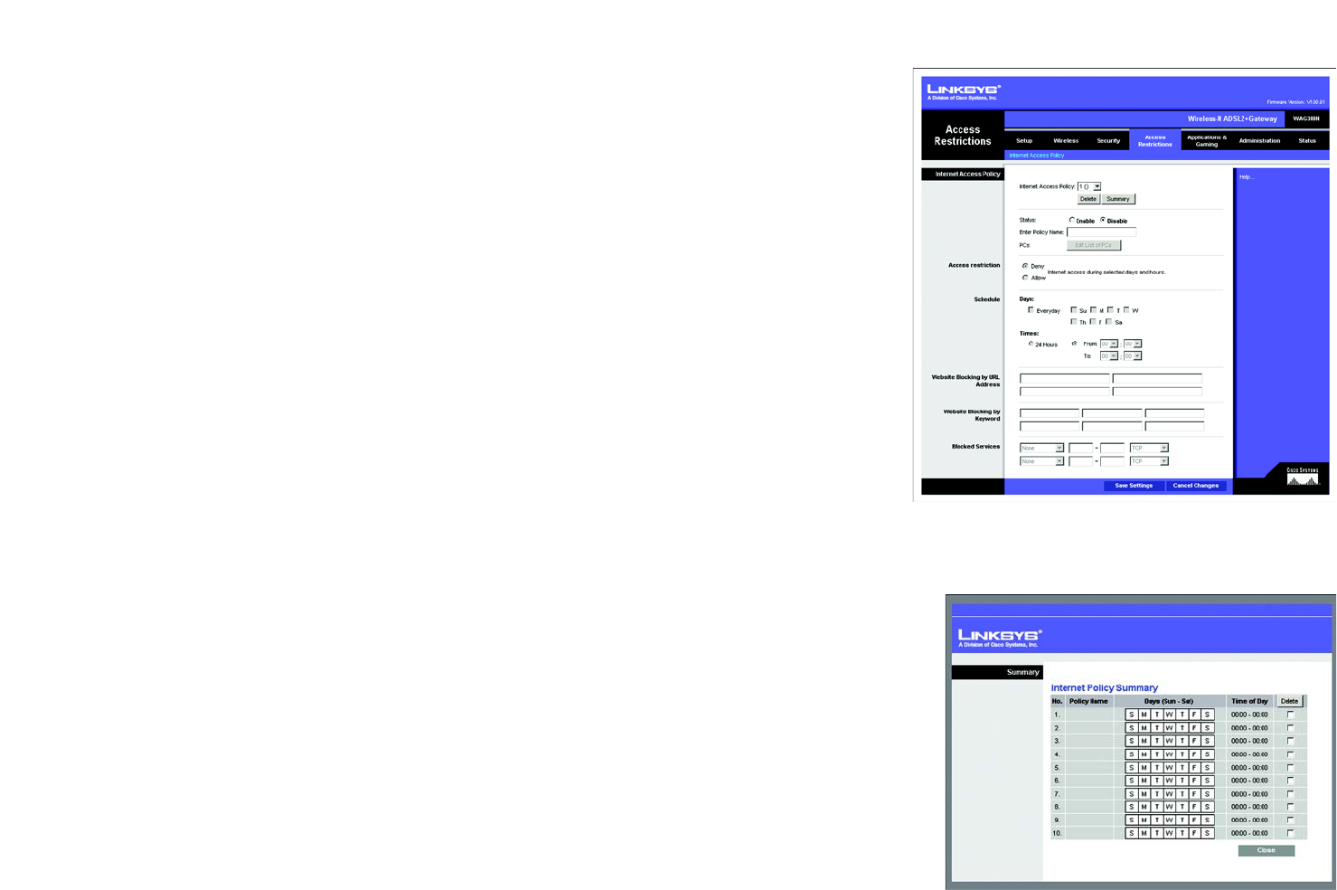
The Internet Access Policy Tab
The Internet Access Policy screen allows you to block or allow specific kinds of Internet usage. You can set up
Internet access policies for specific computers and block websites by URL address or keyword.
Internet Access Policy
Internet Access Policy. Access can be managed by a policy. Use the settings on this screen to establish an access
policy (after the Save Settings button is clicked). Selecting a policy from the drop-down menu will display that
policy’s settings. To delete a policy, select that policy’s number and click the Delete button. To view all the
policies, click the Summary button. (Policies can be deleted from the Summary screen by selecting the policy or
policies and clicking the Delete button. To return to the Internet Access screen, click the Close button.)
Status. Policies are disabled by default. To enable a policy, select the policy number from the drop-down menu,
and click the radio button beside Enable.
To create an Internet Access policy:
1. Select a number from the Internet Access Policy drop-down menu.
2. To enable this policy, click the radio button beside Enable.
3. Enter a Policy Name in the field provided.
Figure 5-25: Internet Access Policy
Figure 5-26: Internet Policy Summary
32
Chapter 5: Configuring the Wireless-N ADSL2+ Gateway
The Access Restrictions Tab
Wireless-N ADSL2+ Gateway
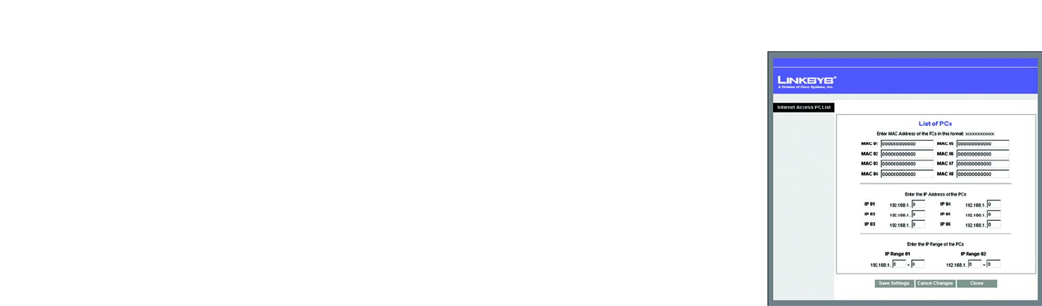
4. Click the Edit List of PCs button to select which PCs will be affected by the policy. The List of PCs screen will
appear. You can select a PC by MAC Address or IP Address. You can also enter a range of IP Addresses if you
want this policy to affect a group of PCs. After making your changes, click the Save Settings button to apply
your changes or Cancel Changes to cancel your changes. Then click the Close button to exit this screen.
5. Click the appropriate option, Deny or Allow, depending on whether you want to block or allow Internet access
for the PCs you listed on the List of PCs screen.
6. Decide which days and what times you want this policy to be enforced. Select the individual days during
which the policy will be in effect, or select Everyday. Then enter a range of hours and minutes during which
the policy will be in effect, or select 24 Hours.
7. If you want to block websites with specific URL addresses, enter each URL in a separate field next to Website
Blocking by URL Address.
8. If you want to block websites using specific keywords, enter each keyword in a separate field next to Website
Blocking by Keyword.
9. You can filter access to various services accessed over the Internet, such as FTP or telnet, by selecting
services from the drop-down menus next to Blocked Services. The port numbers and protocol for the selected
service will be automatically displayed.
If the service you want is not listed, select User-Defined. Enter its port numbers in the fields provided. Then
select its protocol, ICMP, TCP, UDP, or TCP & UDP from the drop-down menu.
10. Click the Save Settings button to save the policy’s settings. To undo the policy’s settings, click the Cancel
Changes button. Click Help for more information.
Figure 5-27: List of PCs
33
Chapter 5: Configuring the Wireless-N ADSL2+ Gateway
The Applications and Gaming Tab
Wireless-N ADSL2+ Gateway
The Applications and Gaming Tab
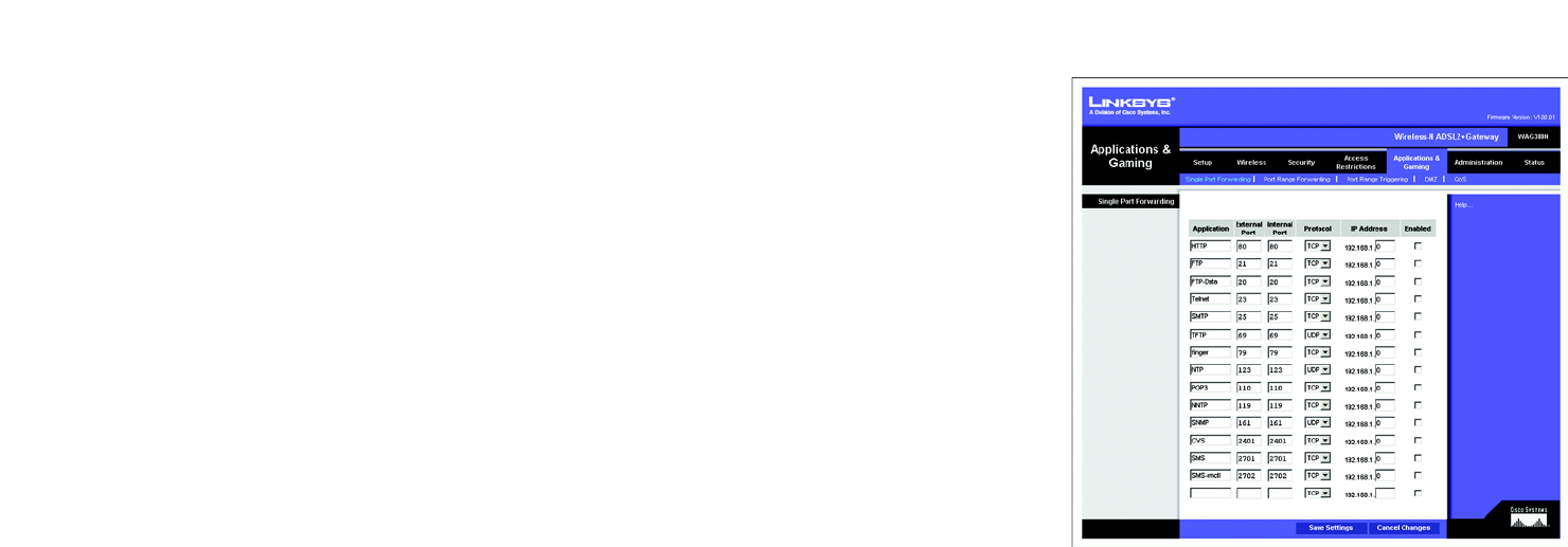
The Single Port Range Forwarding Tab
Use the Single Port Range Forwarding screen when you want to open a specific port so users on the Internet can
see the servers behind the Gateway (such servers may include FTP or e-mail servers). When users send this type
of request to your network via the Internet, the Gateway will forward those requests to the appropriate computer.
Any computer whose port is being forwarded should have its DHCP client function disabled and should have a
new static IP address assigned to it because its IP address may change when using the DHCP function.
Single Port Forwarding
• Application. Enter the name of the application in the field provided.
• External Port and Internal Port. Enter the External and Internal Port numbers.
• Protocol. Select the protocol you wish to use for each application: TCP or UDP.
• IP Address. Enter the IP Address of the appropriate computer.
• Enabled. Click Enabled to enable forwarding for the chosen application.
When finished making your changes on this tab, click the Save Settings button to save these changes, or click
the Cancel Changes button to undo your changes. Click Help for more information.
Figure 5-28: Single Port Forwarding
34
Chapter 5: Configuring the Wireless-N ADSL2+ Gateway
The Applications and Gaming Tab
Wireless-N ADSL2+ Gateway
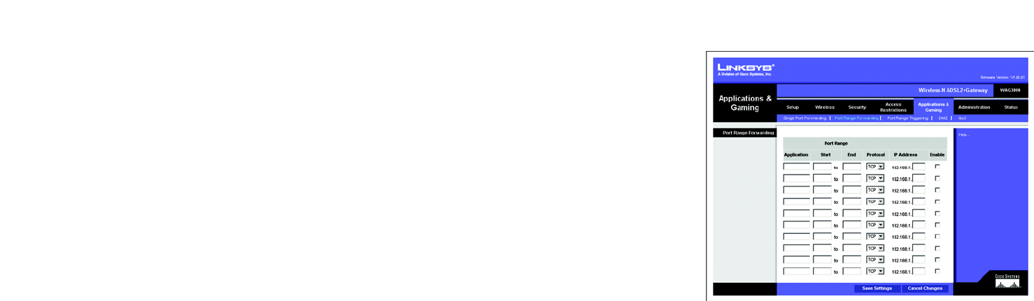
The Port Range Forwarding Tab
The Port Range Forwarding screen sets up public services on your network, such as web servers, ftp servers, e-
mail servers, or other specialized Internet applications. (Specialized Internet applications are any applications
that use Internet access to perform functions such as videoconferencing or online gaming. Some Internet
applications may not require any forwarding.)
When users send this type of request to your network via the Internet, the Gateway will forward those requests to
the appropriate computer. Any computer whose port is being forwarded should have its DHCP client function
disabled and should have a new static IP address assigned to it because its IP address may change when using
the DHCP function.
Port Range Forwarding
• Application. Enter the name of the application in the field provided.
• Start and End. Enter the starting and ending numbers of the port range you wish to forward.
• Protocol. Select the protocol you wish to use for each application: TCP, UDP, or Both.
• IP Address. Enter the IP Address of the appropriate computer.
• Enable. Click the Enable checkbox to enable forwarding for the chosen application.
When finished making your changes on this tab, click the Save Settings button to save these changes, or click
the Cancel Changes button to undo your changes. Click Help for more information.
Figure 5-29: Port Range Forwarding
35
Chapter 5: Configuring the Wireless-N ADSL2+ Gateway
The Applications and Gaming Tab
Wireless-N ADSL2+ Gateway
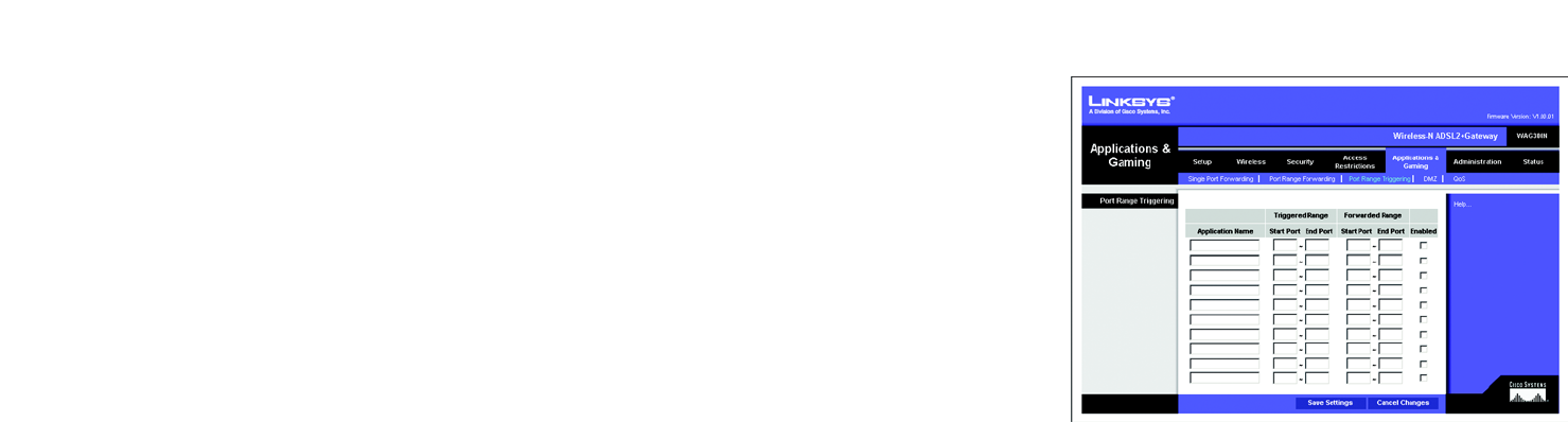
The Port Triggering Tab
Port Triggering is used for special applications that can request a port to be opened on demand. For this feature,
the Gateway will watch outgoing data for specific port numbers. The Gateway will remember the IP address of the
computer that sends a transmission requesting data, so that when the requested data returns through the
Gateway, the data is pulled back to the proper computer by way of IP address and port mapping rules.
Port Range Triggering
• Application. Enter the name you wish to give each application.
• Triggered Range. Enter the starting and ending port numbers of the Triggered Range.
• Forwarded Range. Enter the starting and ending port numbers of the Forwarded Range.
• Enabled. Click the Enabled checkbox to enable port triggering for the chosen application.
When finished making your changes on this tab, click the Save Settings button to save these changes, or click
the Cancel Changes button to undo your changes. Click Help for more information.
Figure 5-30: Port Triggering
36
Chapter 5: Configuring the Wireless-N ADSL2+ Gateway
The Applications and Gaming Tab
Wireless-N ADSL2+ Gateway
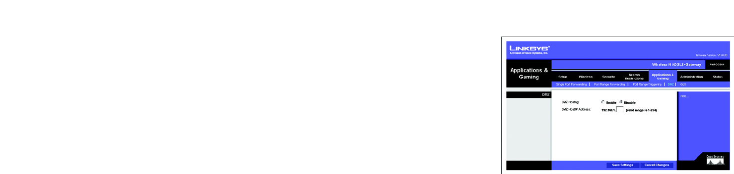
The DMZ Tab
The DMZ screen allows one local user to be exposed to the Internet for use of a special-purpose service such as
Internet gaming and videoconferencing through DMZ Hosting. DMZ hosting forwards all the ports for one
computer at the same time, which differs from Port Range Forwarding, which can only forward a maximum of
10 ranges of ports.
DMZ
• DMZ Hosting. This feature allows one local user to be exposed to the Internet for use of a special-purpose
service such as Internet gaming and videoconferencing. To use this feature, select Enable. To disable DMZ,
select Disable.
• DMZ Host IP Address. To expose one computer, enter the computer’s IP address. To get the IP address of a
computer, refer to “Appendix C: Finding the MAC Address and IP Address for Your Ethernet Adapter.”
When finished making your changes on this tab, click the Save Settings button to save these changes, or click
the Cancel Changes button to undo your changes. Click Help for more information.
Figure 5-31: DMZ
37
Chapter 5: Configuring the Wireless-N ADSL2+ Gateway
The Applications and Gaming Tab
Wireless-N ADSL2+ Gateway
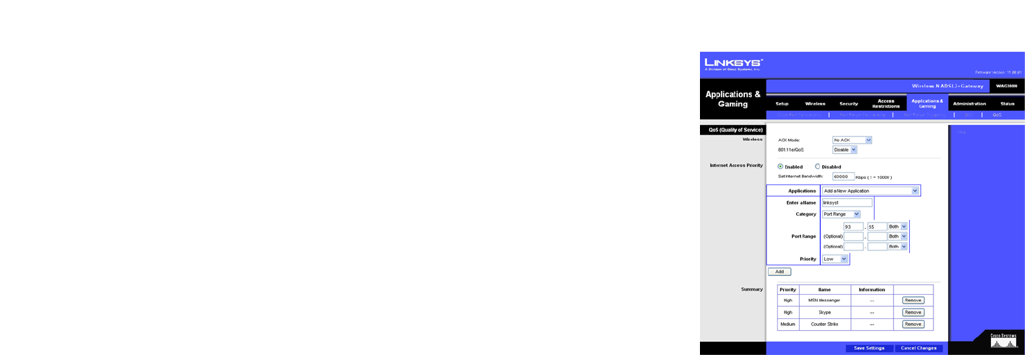
The QoS Tab
QoS (Quality of Service)
QoS ensures better service to high-priority types of network traffic, which may involve demanding, real-time
applications, such as Internet phone calls or videoconferencing.
Wireless
•ACK Mode. This setting prioritizes QoS for users who also have ACK Mode enabled. Users with Immediate
ACK (the default setting) will experience reliable connectivity for normal network use. Burst ACK is faster but
less reliable and may also affect long-range wireless performance. The No ACK setting disables the ACK
feature. Clients utilizing ACK must have their wireless adapter on the same setting as the Gateway. This is
normally used in a multicast broadcast like video. Do not use this unless you are an advanced user.
•802.11e/QoS. QoS will be enabled by default to provide the best performance for your wireless connection.
Select Disable to improve performance for a mixed wireless network.
Internet Access Priority
In this section, you can set priority based on Application, Port Range, or MAC Address. There are four priories you
can set: High, Medium, Normal, or Low.
• Enabled/Disabled. To limit outgoing bandwidth for the QoS policies in use, select Enabled. Otherwise, select
Disabled.
• Set Internet Bandwidth. This setting allows you to limit the outgoing bandwidth for the QoS policies in use, so
you can control how much bandwidth a particular application is allowed to use. Enter the bandwidth in the
field.
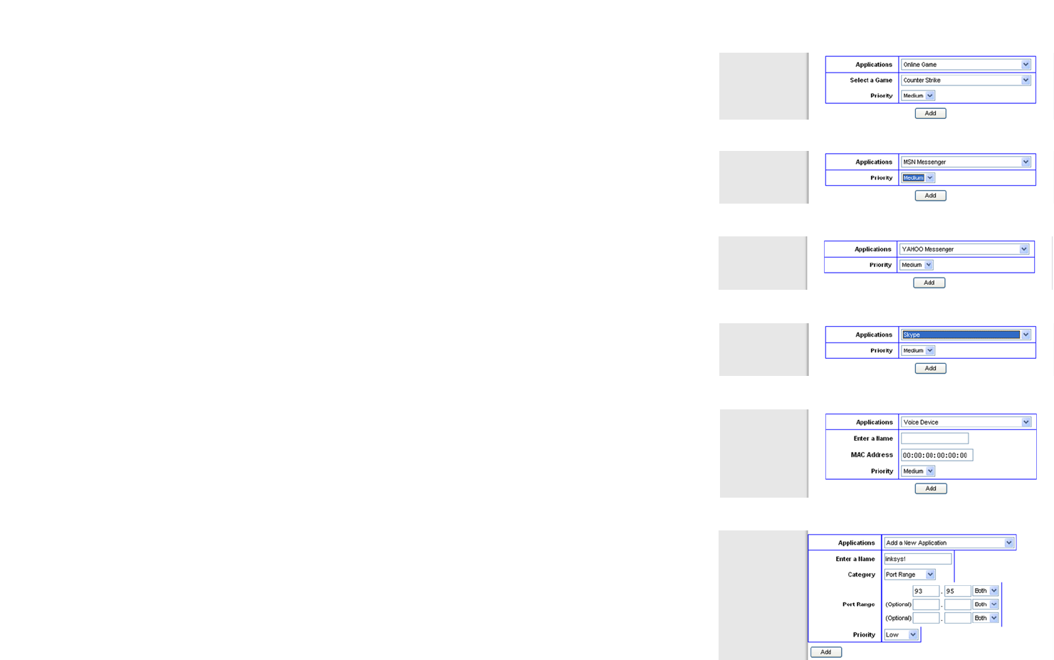
• Application. With this option you can select None, Online Game, MSN Messenger, YAHOO Messenger,
Skype, Voice Device, Add a New Application, or select from the list of applications you want to set. To
create a new entry, select Add a New Application, and refer to the Add a New Application section.
• Priority. Select High, Medium, Normal, or Low for the bandwidth priority you need for the application you
selected. Don’t set all applications to High, because this will defeat the purpose of allocating the available
bandwidth. If you want to select below normal bandwidth, select Low. Depending on the application, a few
attempts may be needed to set the appropriate bandwidth priority. Once you have made your selection, click
Add to add to the Summary list.
Figure 5-32: QoS
38
Chapter 5: Configuring the Wireless-N ADSL2+ Gateway
The Applications and Gaming Tab
Wireless-N ADSL2+ Gateway
Online Game
Select a Game Select a game from the drop-down menu, which lists some common pre-configured games.
Priority Select its priority from the drop-down menu, and click Add.
MSN Messenger
Select its priority from the drop-down menu, and click Add.
YAHOO Messenger
Select its priority from the drop-down menu, and click Add.
Skype
Select its priority from the drop-down menu, and click Add.
Voice Device
Enter a Name Enter the name of your network device.
MAC Address Enter its MAC Address.
Priority Select its priority from the drop-down menu, and click Add.
Add a New Application
Enter a Name Enter any name to indicate the name of the entry.
Category Select from Port Range or MAC Address for the Gateway to use to set the bandwidth priority.
Port Range If you selected Port Range, then this category will be available. It allows you to enter the port
range(s) that the application will be using. For example, if you want to allocate bandwidth for
FTP, you can enter 21-21. If you need services for an application that uses from 1000 to 1250,
you enter 1000-1250 as your settings. Port numbers can range from 1 to 65535. Check your
application's documentation for details on the service ports used.
You can define up to three ranges for this bandwidth allocation. For each port range, designate
the protocol type(s): TCP, UDP, or Both.
MAC Address If you selected MAC Address, then this category will be available. Enter the 12 hexadecimal
digit MAC Address to represent the device you want to set as a bandwidth priority. This is a
Figure 5-34: QoS - MSN Messenger
Figure 5-37: QoS - Voice Device
Figure 5-38: QoS - Add a New Application (Port Range)
Figure 5-33: QoS - Online Game
Figure 5-36: QoS - Skype
Figure 5-35: QoS - YAHOO Messenger
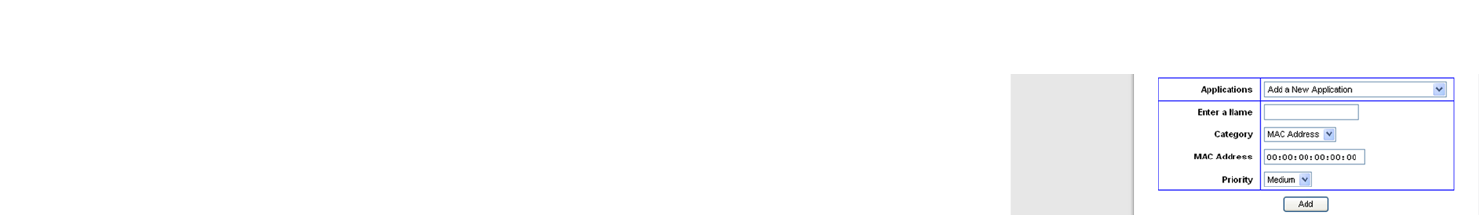
39
Chapter 5: Configuring the Wireless-N ADSL2+ Gateway
The Applications and Gaming Tab
Wireless-N ADSL2+ Gateway
unique identifier for your network device. When the Gateway identifies the device entered, the
Gateway will allocate the priority set for that entry. Check the device’s documentation to obtain
the MAC Address.
Priority Select the bandwidth priority for the application you selected. Select High, Medium, Normal,
or Low for the bandwidth, but don’t set all applications to High. Once you have made your
selection, click Add to add to the Summary list.
Summary
Priority This displays the bandwidth allocation priority of High, Medium, Normal, or Low, that you set
for the application.
Name This displays the application name or the entries you entered to be allocated.
Information This displays the Port Range or MAC Address entered when you added a new application. If a
pre-configured application was selected, there will be no valid entry shown in this section.
Remove This button allows you to remove the application entry. To remove the entry, click the Remove
button. To save the configuration, click the Save Settings button. Otherwise, to cancel, click
the Cancel Changes button.
When finished making your changes on this tab, click the Save Settings button to save these changes, or click
the Cancel Changes button to undo your changes. Click Help for more information.
Figure 5-39: QoS - Add a New Application (MAC Address)
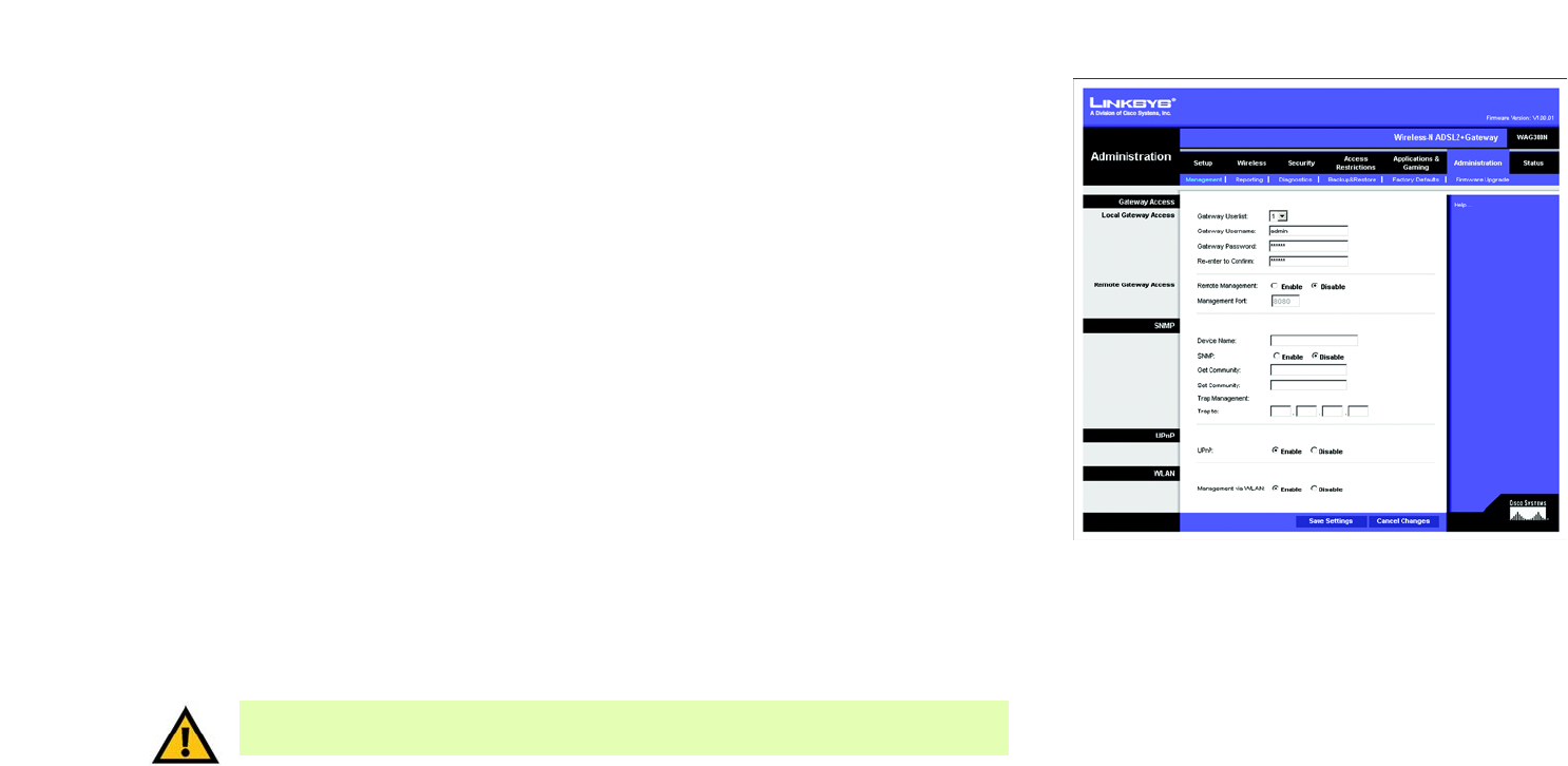
40
Chapter 5: Configuring the Wireless-N ADSL2+ Gateway
The Administration Tab
Wireless-N ADSL2+ Gateway
The Administration Tab
The Management Tab
The Management screen allows you to change the Gateway’s access settings as well as configure the SNMP
(Simple Network Management Protocol), UPnP (Universal Plug and Play), and WLAN management features.
Gateway Access
Local Gateway Access. To ensure the Gateway’s security, you will be asked for your password when you access
the Gateway’s Web-based Utility. The default username and password is admin.
• Gateway Userlist. Select the number of the user from the drop-down menu.
• Gateway Username. Enter the default username, admin. It is recommended that you change the default
username to one of your choice.
• Gateway Password. It is recommended that you change the default password, admin, to one of your choice.
• Re-enter to confirm. Re-enter the Gateway’s new Password to confirm it.
Remote Gateway Access. This feature allows you to access the Gateway from a remote location, via the Internet.
• Remote Management. This feature allows you to manage the Gateway from a remote location via the Internet.
To enable Remote Management, click Enable.
• Management Port. Enter the port number you will use to remotely access the Gateway.
SNMP
SNMP is a popular network monitoring and management protocol.
• Device Name. Enter the name of the Gateway.
• SNMP. To enable SNMP, click Enable. To disable SNMP, click Disable.
• Get Community. Enter the password that allows read-only access to the Gateway’s SNMP information.
Figure 5-40: Management
IMPORTANT: Enabling remote management allows anyone with your password to configure the
Gateway from somewhere else on the Internet.

41
Chapter 5: Configuring the Wireless-N ADSL2+ Gateway
The Administration Tab
Wireless-N ADSL2+ Gateway
• Set Community. Enter the password that allows read/write access to the Gateway’s SNMP information.
• Trap Management: Trap to. Enter the IP address of the remote host computer that will receive the trap
messages.
UPnP
UPnP allows Windows Me and XP to automatically configure the Gateway for various Internet applications, such
as gaming and videoconferencing.
• UPnP. To enable UPnP, click Enable. Otherwise, click Disable.
WLAN
• Management via WLAN. This feature allows the Gateway to be managed by a wireless computer on the local
network when it logs into the Gateway’s Web-based Utility. To enable this feature, click Enable. Otherwise,
click Disable.
When finished making your changes on this tab, click the Save Settings button to save these changes, or click
the Cancel Changes button to undo your changes. Click Help for more information.
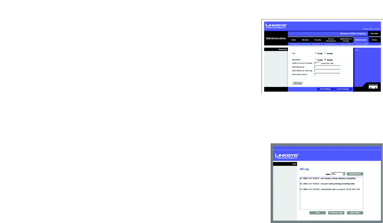
42
Chapter 5: Configuring the Wireless-N ADSL2+ Gateway
The Administration Tab
Wireless-N ADSL2+ Gateway
The Reporting Tab
The Reporting screen provides you with a log of all incoming and outgoing URLs or IP addresses for your Internet
connection. It also provides logs for VPN and firewall events.
Reporting
• Log. To enable log reporting, click Enable.
Email Alerts
• E-Mail Alerts. To enable E-Mail Alerts, click Enable.
• Denial of Service Thresholds. Enter the number of Denial of Service attacks that will trigger an e-mail alert.
• SMTP Mail Server. Enter the IP address of the SMTP server.
• E-Mail Address for Alert Logs. Enter the e-mail address that will receive alert logs.
• Return E-Mail address. Enter the return address for the e-mail alerts.
To view the logs, click the View Logs button. A new screen will appear. From the drop-down menu, select which
log you want to view: ALL, System Log, Access Log, or Firewall Log. Click the pageRefresh button to refresh
the information. Click the Clear button to clear the log information. Click the Previous Page button to go to the
previous page of information. Click the Next Page button to move to the next page of information.
When finished making your changes on this tab, click the Save Settings button to save these changes, or click
the Cancel Changes button to undo your changes. Click Help for more information.
Figure 5-42: View Log
Figure 5-41: Reporting
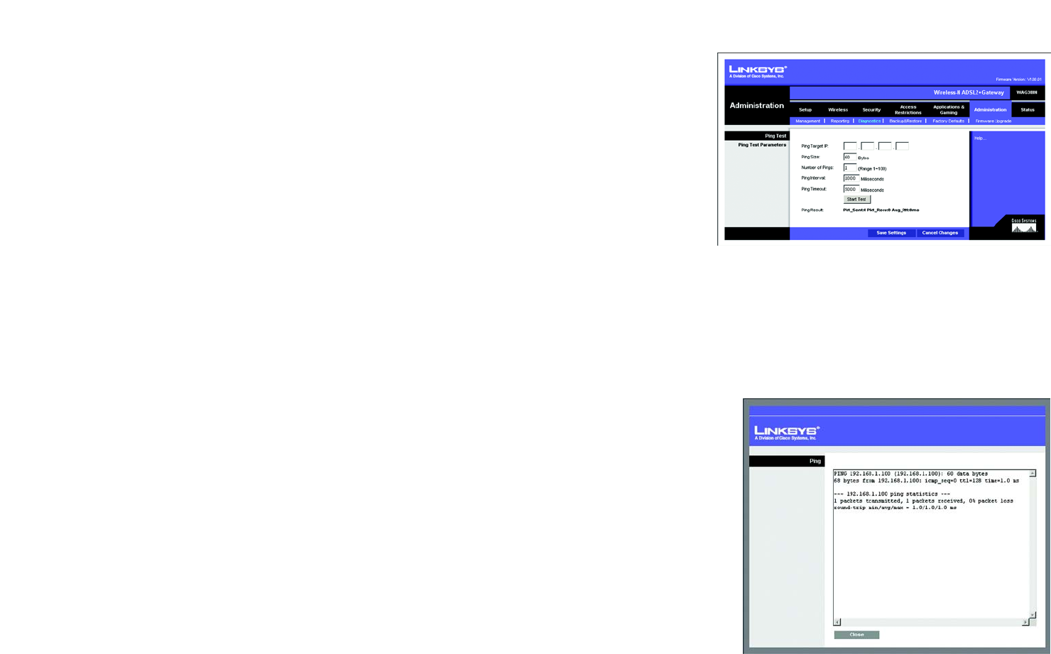
43
Chapter 5: Configuring the Wireless-N ADSL2+ Gateway
The Administration Tab
Wireless-N ADSL2+ Gateway
The Diagnostics Tab
Use this screen to run ping tests and display test results.
Ping Test
Ping Test Parameters
• Ping Target IP. Enter the IP address that you want to ping. This can be either a local (LAN) IP or an Internet
(WAN) IP address.
• Ping Size. Enter the size of the packet.
• Number of Pings. Enter the number of times that you want to ping.
• Ping Interval. Enter the ping interval (how often the target IP address will be pinged) in milliseconds.
• Ping Timeout. Enter the ping timeout (how long before the ping test times out) in milliseconds.
Click the Start Test button to start the Ping Test.
• Ping Result. The results of the ping test will be shown here.
When finished making your changes on this tab, click the Save Settings button to save these changes, or click
the Cancel Changes button to undo your changes. Click Help for more information.
Figure 5-43: Diagnostics
Figure 5-44: Ping Test
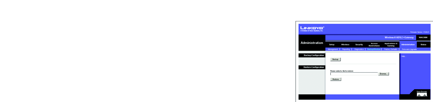
44
Chapter 5: Configuring the Wireless-N ADSL2+ Gateway
The Administration Tab
Wireless-N ADSL2+ Gateway
The Backup & Restore Tab
The Backup & Restore tab allows you to back up and restore the Gateway’s configuration file.
Backup Configuration
To back up the Gateway’s configuration file, click the Backup button. Then follow the on-screen instructions.
Restore Configuration
To restore the Gateway’s configuration file, click the Browse button. Then follow the on-screen instructions to
locate the file. After you have selected the file, click the Restore button.
Click Help for more information. Figure 5-45: Backup & Restore