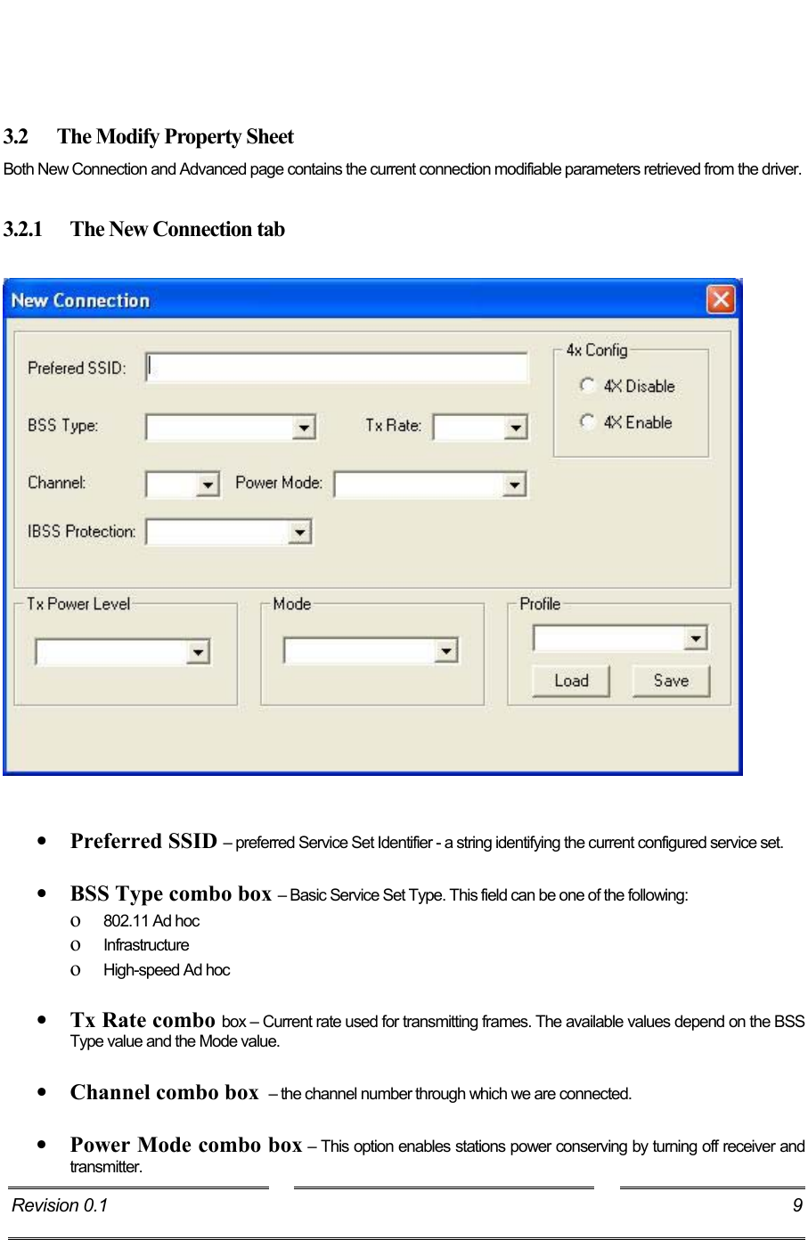
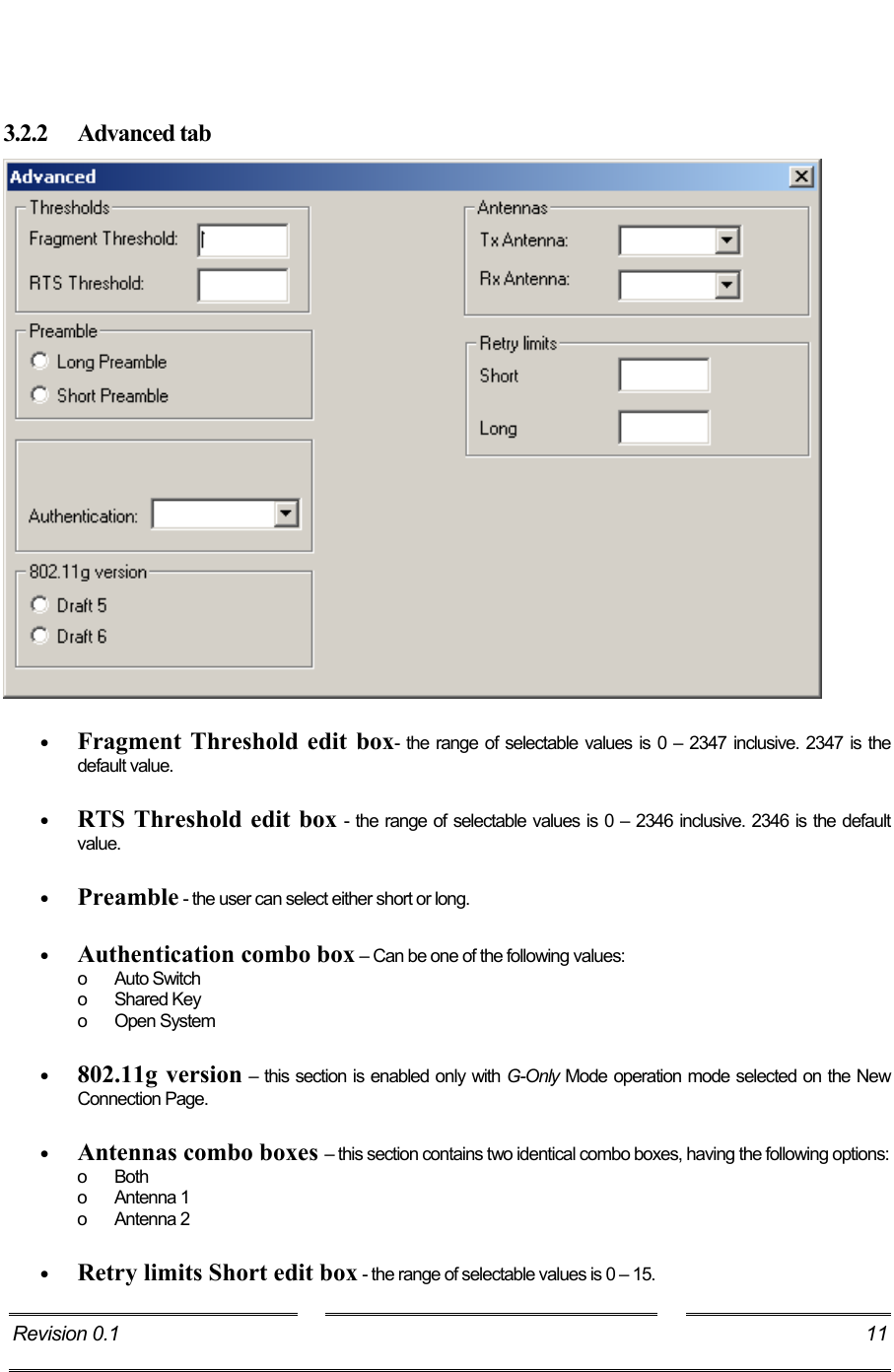
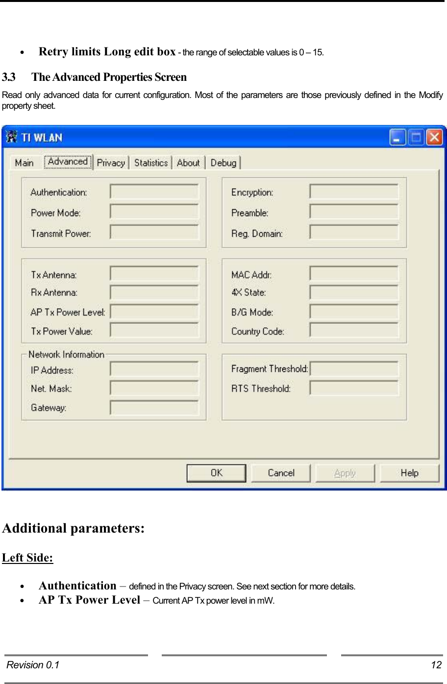
LINKSYS WAG54GV2M WLAN 802.11g MiniPCI Card User Manual

LINKSYS LLC WLAN 802.11g MiniPCI Card Users Manual

Users Manual

                 Configuration Utility  User’s Guide Revision 0.1  1
     1 Introduction........................................................................................................................... 3 1.1 List of abbreviations and Terms............................................................................................ 3 2 Installation............................................................................................................................. 4 3 Using the TI WLAN CU....................................................................................................... 5 3.1 The Main (Status) Screen ....................................................................................................... 6 3.2 The Modify Property Sheet .................................................................................................... 9 3.2.1  The New Connection tab ............................................................................ 9 3.2.2 Advanced tab ............................................................................................ 11 3.3 The Advanced Properties Screen......................................................................................... 12 3.4 The Privacy Screen ................................................................................................................ 14 3.4.1 The WEP Screen....................................................................................... 15 3.4.2  The CCX Configuration Screen................................................................ 16 3.5 The Statistics Screen .............................................................................................................. 17 3.6 The About Screen................................................................................................................... 18 3.7 Debug Screen .......................................................................................................................... 19 3.7.1  Debug Tab activation................................................................................ 19 3.7.2  Debug Screen options ............................................................................... 20  Revision 0.1  2 Technology,Inc.
    1 Introduction The configuration utility provides displaying and changing parameters of the TI WLAN driver. 1.1  List of abbreviations and Terms  AES     - Advanced Encryption Standard AP     - Access Point BSS    - Basic Service Set BSSID    - Basic Service Set Identifier CU     - Configuration Utility FCS     - Frame Check Sequence GUI    - Graphical User Interface  IBSS     - Independent Basic Service Set LEAP     - Lightweight Extensible Authentication Protocol MAC     - Medium Access Control MSDU    - MAC Service Data Unit PBCC    - Packet Broadcast Control Channel PRS    - Product Requirements Specification RSSI     - Received Signal Strength Indication SSID    - Service Set Identifier SSN    - Sub System Number TI    - Texas Instruments Inc. TKIP    - Temporal Key Integrity Protocol WEP     - Wired Equivalent Privacy WiFi     - Wireless Fidelity WPA     - WiFi Protected Access WLAN     - Wireless Local Area Network Revision 0.1  3
   2 Installation  Revision 0.1  4
   3 Using the TI WLAN CU Important Notes: •  In case that the device was not installed properly or that it is disconnected, all buttons, combo boxes, edit boxes etc. will be disabled. Also the status text in the main window will be set to Driver not loaded.  •  To save any changes – press the Apply button. Changes will not be saved if changed focus to another tab without previously clicking the Apply button.  •  Pressing the OK / Cancel button from the main property sheet will minimize the application to the task bar. In case that there were changes, clicking the Cancel button will return the displayed data to the one stored on the driver. Another click will minimize the application to the task bar. Left click the application icon on the task bar, or right click and choose Restore to restore it. Choose Exit to exit the application. Revision 0.1  5
    3.1  The Main (Status) Screen The Main Screen is the main page for the CU. It contains the available 802.11 networks and the current configuration basic data. It enables rescanning the network, modifying the current configuration parameters and connecting to each one of the listed SSIDs. It also enables activating and deactivating of using an external configuration.   Revision 0.1  6
     Getting Started:  In order to connect to a network, do the following:  1) In the Available Networks Window the currently available networks are displayed. In order to connect to a specific network – select the appropriate raw (will be highlighted as a result)  2)  Click on the Connect button (another option is to double click the appropriate raw). After doing so, the CU will attempt associating with the chosen network. If there are no available networks on the available networks window, you can choose to rescan for currently available networks by pressing the Rescan button.  After choosing a network, a basic connection data will be displayed on the screen. See Displayed data section for details.  If no network is available or refreshing the available networks list is desired – click on the Rescan button.  Displayed data:  Status – can be one the following:  •  Driver not loaded    – driver not installed or not inserted. •  Disconnected from network – disconnected from current configured SSID. •  Connecting to network  –   while in the process of connecting. •  Connected to network  –  connected to current configured SSID. •  Scanning network    –  scanning network for available SSIDs. •  Not connected to network  – sidle status  Current configuration  -  provides read-only status information of the current active connection. •  Pref: SSID  -  Preferred Service Set Identifier. •  BSS Type  -  Basic Service Set Type. •  BSSID   -  Basic Service Set Identifier. •  Channe - the channel number through which we are connected. •  Tx Rate  -  current rate used for transmitting frames.  For more information, see section 3.2.1   Signal quality   –  displays the Received Signal Strength Indication as a percentage bar.  Tx Rate Rx Rate    displays instantaneous transmit and receive rates, in a graphical format. These values are being refreshed every second. Revision 0.1  7
    Modifying Current Connection Parameters  To modify the current connection parameters, click the Modify button. So, a new property sheet will be opened. This property sheet contains two pages named ‘”New connection” and “Advanced”, see section 3.2.1 , see section 3.2.2 .   Advanced Configuration  Check the External Configuration check box for enabling privacy external configuration. By doing so, all three buttons (Connect, Modify and Rescan) will be disabled, see section 3.4 – Privacy Screen for more details.  Summary  Connect button – use this button to initiate a connection to the network chosen in the Available Networks Window.  Rescan button –use this button to rescan and update the Available Networks Window.  Modify button – use this button to modify the current connection parameters.  External Configuration check box – check this check box for enabling privacy external configuration. Revision 0.1  8
    3.2  The Modify Property Sheet Both New Connection and Advanced page contains the current connection modifiable parameters retrieved from the driver.  3.2.1  The New Connection tab      •  Preferred SSID – preferred Service Set Identifier - a string identifying the current configured service set.  •  BSS Type combo box – Basic Service Set Type. This field can be one of the following:  o  802.11 Ad hoc o  Infrastructure o  High-speed Ad hoc   •  Tx Rate combo box – Current rate used for transmitting frames. The available values depend on the BSS Type value and the Mode value.   •  Channel combo box  – the channel number through which we are connected.  •  Power Mode combo box – This option enables stations power conserving by turning off receiver and transmitter. Revision 0.1  9
    •  This field contains the following values: o  No Power Save o  Max Power Save  •  IBSS Protection combo box – Independent Basic Service Set protection can be one of the following: o None  o  TI Protection  o CTS Only  •  4x Config radio button – select “4x enable” to enable 4x mode, and “4x disable “to disable it. •  Tx Power Level combo box – Transmit power level. Can be one of the following: o Low Power o Medium-Low Power o Medium-Power o Medium-High Power o High Power  •  Mode combo box – selection of one of the standard 802.11 operating modes: o B-Only Mode o B-Plus Mode o B&G Mode o G-Only Mode o  A-Only Mode  o A&G Mode  •  Profile – Save a profile or load a stored profile. To save profile, enter a profile name within the combo box and press save. To load an existing profile, choose the profile name from the comb box and press load. All of the current configuration parameters will be changed to the saved profile parameters. Revision 0.1  10
     3.2.2 Advanced tab   •  Fragment Threshold edit box- the range of selectable values is 0 – 2347 inclusive. 2347 is the default value.  •  RTS Threshold edit box - the range of selectable values is 0 – 2346 inclusive. 2346 is the default value.  •  Preamble - the user can select either short or long.  •  Authentication combo box – Can be one of the following values: o Auto Switch o Shared Key o Open System  •  802.11g version – this section is enabled only with G-Only Mode operation mode selected on the New Connection Page.   •  Antennas combo boxes – this section contains two identical combo boxes, having the following options: o Both o Antenna 1 o Antenna 2  •  Retry limits Short edit box - the range of selectable values is 0 – 15. Revision 0.1  11
    •  Retry limits Long edit box - the range of selectable values is 0 – 15. 3.3  The Advanced Properties Screen Read only advanced data for current configuration. Most of the parameters are those previously defined in the Modify property sheet.      Additional parameters:  Left Side:  •  Authentication – defined in the Privacy screen. See next section for more details. •  AP Tx Power Level – Current AP Tx power level in mW. Revision 0.1    12
    Network Information •  IP Address  •  Net. Mask •  Gateway   Right side: •  Encryption – defined in the Privacy screen. See next section for more details.  •  Regulatory Domain – can be one of the following: For 2.4 GHz: o FCC o IC o ETSI o Spain o France o MKK o MKK1 o Unknown For 5 GHz: o US o World Band o Extended World Band  •  MAC Addr  - MAC address  •  Country Code – represented by a 3 maximum length string. Revision 0.1  13
   3.4 The Privacy Screen  Note: This window will be disabled in case that the External Configuration check box (in the Main window) was checked. In this screen the privacy mode is being configured. There are 3 optional privacy modes: •  None – no security defined. •  WEP -for WEP key defining. Press the Select button to change WEP configuration. A new dialog window will be opened (see section 3.4.1). •  CCX - for CCX configuration. Press the Select button to change CCX configuration. A new dialog window will be opened (see section 3.4.2). Revision 0.1  14
   To use the external mode (privacy configured by Funk’s Odyssey software), check the External Configuration check box in the main dialog and press the Apply button. All privacy configurations will be disabled, until you uncheck the External Configuration check box. 3.4.1 The WEP Screen   Configure WEP keys: •  Choose key size form the key size combo box. Available values - 40 bit, 128 bit, 256 bit. •  Add an encryption string within the Encryption edit box. •  Choose authentication type from the Authentication combo box.  Available values – Open System, Shared Key, Auto Switch •  Select default key by pressing the desired radio button.  Press OK to save and return to previous dialog, or cancel to cancel changes and return to the previous dialog.  Revision 0.1  15
   3.4.2  The CCX Configuration Screen   Select an option from the Network Security Type combo box.  Available options are:  •  None – choosing it will enable the WEP Select button. By pressing it you will get to the same window as described in see section 3.4.1 •  LEAP – choosing it will enable the Leap Credentials group box, where you can type the user ID and password. •  External –external CCX configuration.  Press OK to save and return to previous dialog, or cancel to cancel changes and return to the previous dialog. Revision 0.1   16
    3.5  The Statistics Screen Contains general statistics data retrieved from the driver.   Revision 0.1  17
    3.6 The About Screen The about screen contains general version data.   Revision 0.1  18
    3.7 Debug Screen 3.7.1 Debug Tab activation Add the following text to shortcut definition as it shown on picture below.   Revision 0.1   19
    3.7.2  Debug Screen options The debug screen is used for directly accessing the hardware.  Revision 0.1  20
 Federal Communication Commission Interference Statement This equipment has been tested and found to comply with the limits fora Class B digital device, pursuant to Part 15 of the FCC Rules.  Theselimits are designed to provide reasonable protection against harmfulinterference in a residential installation.  This equipment generates,uses and can radiate radio frequency energy and, if not installed andused in accordance with the instructions, may cause harmfulinterference to radio communications.  However, there is no guaranteethat interference will not occur in a particular installation.  If thisequipment does cause harmful interference to radio or televisionreception, which can be determined by turning the equipment off and on,the user is encouraged to try to correct the interference by one of thefollowing measures:  -Reorient or relocate the receiving antenna. -Increase the separation between the equipment and receiver. -Connect the equipment into an outlet on a circuit different from that to which the receiver is connected. -Consult the dealer or an experienced radio/TV technician for help.  This device complies with Part 15 of the FCC Rules. Operation issubject to the following two conditions: (1) This device may not causeharmful interference, and (2) this device must accept any interferencereceived, including interference that may cause undesired operation.  FCC Caution: Any changes or modifications not expressly approved bythe party responsible for compliance could void the user's authority tooperate this equipment.  IMPORTANT NOTE: FCC Radiation Exposure Statement: This equipment complies with FCC radiation exposure limits set forth for anuncontrolled environment. This equipment should be installed and operatedwith minimum distance 20cm between the radiator & your body. This transmitter must not be co-located or operating in conjunction with anyother antenna or transmitter.
This device is intended only for OEM integrators under the followingconditions:1) The antenna must be installed such that 20 cm is maintained between theantenna and users, and2) The transmitter module may not be co-located with any other transmitter orantenna.As long as 2 conditions above are met, further transmitter test will not berequired. However, the OEM integrator is still responsible for testing their end-product for any additional compliance requirements required with this moduleinstalled (for example, Wireless AP , Wireless Router).IMPORTANT NOTE: In the event that these conditions can not be met (forexample certain laptop configurations or co-location with another transmitter),then the FCC authorization is no longer considered valid and the FCC ID cannot be used on the final product. In these circumstances, the OEM integratorwill be responsible for re-evaluating the end product (including the transmitter)and obtaining a separate FCC authorization.End Product LabelingThis transmitter module is authorized only for use in device where the antennamay be installed such that 20 cm may be maintained between the antenna andusers (for example, wireless AP , Wireless Router). The final end product mustbe labeled in a visible area with the following: “Contains TX FCC ID: Q87-WAG54GV2M”.Manual Information That Must be IncludedThe OEM integrator has to be aware not to provide information to the end userregarding how to install or remove this RF module in the users manual of theend product which integrate this module.The users manual for OEM integrators must include the following informationin a prominent location “ IMPORTANT NOTE: To comply with FCC RFexposure compliance requirements, the antenna used for this transmitter mustbe installed to provide a separation distance of at least 20 cm from all personsand must not be co-located or operating in conjunction with any other antennaor transmitter.Cisco-Linksys, LLC declare that WAG54GV2M  (WLAN 802.11g MiniPCI Card) is limited in CH1~CH11 by specified firmware controlled in USA."

Navigation menu