LINKSYS WAP54GP Wireless-G Access Point with POE User Manual Book
LINKSYS LLC Wireless-G Access Point with POE Book
LINKSYS >
Contents
- 1. Users Manual 1
- 2. Users Manual 2
- 3. Users Manual 3
- 4. Users Manual 4
Users Manual 1
A Division of Cisco Systems, Inc.
®
Model No.
Access Point with
Wireless-G
WAP54GP
User Guide
WIRELESS
GHz
2.4
802.11g
Power Over Ethernet

Wireless-G Access Point with Power Over Ethernet
Copyright and Trademarks
Specifications are subject to change without notice. Linksys is a registered trademark or trademark of Cisco
Systems, Inc. and/or its affiliates in the U.S. and certain other countries. Copyright © 2005 Cisco Systems, Inc. All
rights reserved. Other brands and product names are trademarks or registered trademarks of their respective
holders.
How to Use this User Guide
The user guide to the Wireless-G Access Point with Power Over Ethernet has been designed to make
understanding networking with the Access Point easier than ever. Look for the following items when reading this
User Guide:
In addition to these symbols, there are definitions for technical terms that are presented like this:
Also, each figure (diagram, screenshot, or other image) is provided with a figure number and description, like
this:
Figure numbers and descriptions can also be found in the “List of Figures” section.
This exclamation point means there is a caution or
warning and is something that could damage your
property or the Access Point.
word: definition.
This checkmark means there is a note of interest and
is something you should pay special attention to while
using the Access Point.
This question mark provides you with a reminder about
something you might need to do while using the Access Point.
Figure 0-1: Sample Figure Description
WAP54GP-UG-50422NC JL
WARNING: This product contains chemicals, including lead, known
to the State of California to cause cancer, and birth defects or other
reproductive harm. Wash hands after handling.

Wireless-G Access Point with Power Over Ethernet
Table of Contents
Chapter 1: Introduction 1
Welcome 1
What’s in this User Guide? 2
Chapter 2: Planning Your Wireless Network 4
Network Topology 4
Roaming 4
Network Layout 5
Chapter 3: Getting to Know the Wireless-G Access Point with Power
Over Ethernet 6
The Front Panel 6
The Back Panel 7
Chapter 4: Connecting the Wireless-G Access Point with Power Over Ethernet 8
Overview 8
Connections for Setup 8
Placement Options 9
Chapter 5: Setting Up the Wireless-G Access Point with Power Over Ethernet 10
Setup Wizard 10
Chapter 6: Configuring the Wireless-G Access Point with Power Over Ethernet 19
Overview 19
Navigating the Utility 19
Accessing the Utility 21
The Setup Tab 21
The Wireless - Basic Wireless Settings Tab 23
The Wireless - Wireless Security Tab 25
The Wireless - Wireless Network Access Tab 29
The Wireless - Advanced Wireless Settings Tab 30
The AP Mode Tab 32
The Administration - Management Tab 35
The Administration - Log Tab 37
The Administration - Factory Default Tab 38
The Administration - Firmware Upgrade Tab 38
The Administration - Language Upgrade Tab 39

Wireless-G Access Point with Power Over Ethernet
The Administration - Reboot Tab 39
The Administration - Config Management Tab 40
The Status - Local Network Tab 41
The Status - Wireless Tab 42
The Status - System Performance Tab 43
Appendix A: Troubleshooting 45
Frequently Asked Questions 45
Appendix B: Wireless Security 49
Security Precautions 49
Security Threats Facing Wireless Networks 49
Appendix C: Upgrading Firmware 52
Appendix D: Windows Help 53
Appendix E: Glossary 54
Appendix F: Specifications 61
Appendix G: Warranty Information 63
Appendix H: Regulatory Information 64
Appendix I: Contact Information 70

Wireless-G Access Point with Power Over Ethernet
List of Figures
Figure 3-1: Front Panel 6
Figure 3-2: Back Panel 7
Figure 4-1: Connect the Ethernet Network Cable 8
Figure 4-2: Connect the Power 8
Figure 4-3: The Access Point’s Stand Slots 9
Figure 4-4: The Access Point’s Wall-Mount Slots 9
Figure 5-1: Setup Wizard’s Welcome Screen 10
Figure 5-2: Connect the Network Cable to Your Switch or Router 11
Figure 5-3: Connect the Network Cable to the Access Point 11
Figure 5-4: Power on the Access Point 12
Figure 5-5: Check the Access Point’s Status 12
Figure 5-6: Select an Access Point 13
Figure 5-7: Login Screen 13
Figure 5-8: Configure Network Address Settings Screen 14
Figure 5-9: Wireless Settings Screen 15
Figure 5-10: Wireless Security Settings - WEP Screen 16
Figure 5-11: Wireless Security Settings - WPA-Personal Screen 17
Figure 5-12: Wireless Power Management Screen 17
Figure 5-13: Confirmation Screen 18
Figure 5-14: Congratulations Screen 18
Figure 6-1: Login Screen 21
Figure 6-2: Setup - Automatic Configuration - DHCP Screen 21
Figure 6-3: Setup - Static IP Address Screen 22
Figure 6-4: Wireless - Basic Wireless Settings Screen 23
Figure 6-5: Wireless - Wireless Security (WPA-Personal) Screen 25
Figure 6-6: Wireless Security - WPA-Enterprise Screen 26
Figure 6-7: Wireless Security - RADIUS Screen 27
Figure 6-8: Wireless Security - WEP Screen 28

Wireless-G Access Point with Power Over Ethernet
Figure 6-9: Wireless - Wireless Network Access Screen 29
Figure 6-10: Select MAC Address Screen 29
Figure 6-11: Wireless - Advanced Wireless Settings Screen 30
Figure 6-12: AP Mode Screen 32
Figure 6-13: Wireless Repeater Diagram 33
Figure 6-14: Site Survey Screen 33
Figure 6-15: Wireless Bridge Diagram 34
Figure 6-16: Administration - Management Screen 35
Figure 6-17: Administration - Log Screen 37
Figure 6-18: Administration - Factory Default Screen 38
Figure 6-19: Administration - Firmware Upgrade Screen 38
Figure 6-20: Administration - Language Upgrade Screen 39
Figure 6-21: Administration - Reboot Screen 39
Figure 6-22: Administration - Config Management Screen 40
Figure 6-23: Status - Local Network Screen 41
Figure 6-24: Status - Wireless Screen 42
Figure 6-25: Status - System Performance Screen 43
Figure C-1: Firmware Upgrade 52

1
Chapter 1: Introduction
Welcome
Wireless-G Access Point with Power Over Ethernet
Chapter 1: Introduction
Welcome
Thank you for choosing the Wireless-G Access Point with Power Over Ethernet. This Access Point will allow you to
network wirelessly better than ever.
How does the Access Point do all of this? An access point allows for greater range and mobility within your
wireless network while also allowing you to connect the wireless network to a wired environment. In fact, the
Wireless-G Access Point with Power Over Ethernet can support communications on up to eight wireless
networks, using Virtual Local Area Network (VLAN) technology.
The Wireless-G Access Point with Power Over Ethernet also offers the convenience of Power over Ethernet (PoE)
capability, so it can receive data and power over a single Ethernet network cable.
But what does all of this mean?
Networks are useful tools for sharing computer resources. You can access one printer from different computers
and access data located on another computer's hard drive. Networks are even used for playing multiplayer video
games. So, networks are not only useful in homes and offices, they can also be fun.
PCs on a wired network create a LAN, or Local Area Network. They are connected with Ethernet cables, which is
why the network is called "wired".
PCs equipped with wireless cards and adapters can communicate without cumbersome cables. By sharing the
same wireless settings, within their transmission radius, they form a wireless network. This is sometimes called
a WLAN, or Wired Local Area Network. The Access Point bridges wireless networks of both 802.11g and 802.11b
standards and wired networks.
Use the instructions in this Guide to help you connect the Access Point, set it up, and configure it to bridge your
different networks. These instructions should be all you need to get the most out of the Access Point.
802.11b: a wireless networking standard that specifies a
maximum data transfer rate of 11Mbps and an operating
frequency of 2.4GHz.
802.11g: a wireless networking standard that specifies a
maximum data transfer rate of 54Mbps, an operating
frequency of 2.4GHz, and backward compatibility with
802.11b devices.
adapter: a device that adds network functionality to your
PC.
ethernet: network protocol that specifies how data is
placed on and retrieved from a common transmission
medium.
lan (local area network): the computers and networking
products that make up your local network.
network: a series of computers or devices connected
together.
poe (power over ethernet): a technology enabling an
Ethernet network cable to deliver both data and power.
access point: a device that allows wireless-equipped
computers and other devices to communicate with a wired
network. Also used to expand the range of a wireless
network.

2
Chapter 1: Introduction
What’s in this User Guide?
Wireless-G Access Point with Power Over Ethernet
What’s in this User Guide?
This user guide covers the steps for setting up and using the Wireless-G Access Point with Power Over Ethernet.
• Chapter 1: Introduction
This chapter describes the Access Point’s applications and this User Guide.
• Chapter 2: Planning your Wireless Network
This chapter describes the basics of wireless networking.
• Chapter 3: Getting to Know the Wireless-G Access Point with Power Over Ethernet
This chapter describes the physical features of the Access Point.
• Chapter 4: Connecting the Wireless-G Access Point with Power Over Ethernet
This chapter instructs you on how to connect the Access Point to your network.
• Chapter 5: Setting Up the Wireless-G Access Point with Power Over Ethernet
This chapter explains how to use the Setup Wizard to configure the settings on the Access Point.
• Chapter 6: Configuring the Wireless-G Access Point with Power Over Ethernet
This chapter explains how to use the Access Point’s Web-based Utility for advanced configuration.
• Appendix A: Troubleshooting
This appendix describes some frequently asked questions regarding installation and use of the Access Point.
• Appendix B: Wireless Security
This appendix explains the risks of wireless networking and some solutions to reduce the risks.
• Appendix C: Upgrading Firmware
This appendix instructs you on how to upgrade the Access Point’s firmware.
• Appendix D: Windows Help
This appendix describes some of the ways Windows can help you with wireless networking.
• Appendix E: Glossary
This appendix gives a brief glossary of terms frequently used in networking.
• Appendix F: Specifications
This appendix provides the Access Point’s technical specifications.
• Appendix G: Warranty Information
This appendix supplies the Access Point’s warranty information.

3
Chapter 1: Introduction
What’s in this User Guide?
Wireless-G Access Point with Power Over Ethernet
• Appendix H: Regulatory Information
This appendix supplies the Access Point’s regulatory information.
• Appendix I: Contact Information
This appendix provides contact information for a variety of Linksys resources, including Technical Support.

4
Chapter 2: Planning Your Wireless Network
Network Topology
Wireless-G Access Point with Power Over Ethernet
Chapter 2: Planning Your Wireless Network
Network Topology
A wireless network is a group of computers, each equipped with one wireless adapter. Computers in a wireless
network must be configured to share the same radio channel. Several PCs equipped with wireless cards or
adapters can communicate with one another to form an ad-hoc network.
Linksys wireless adapters also provide users access to a wired network when using an access point, such as the
Wireless-G Access Point with Power Over Ethernet, or wireless router. An integrated wireless and wired network
is called an infrastructure network. Each wireless PC in an infrastructure network can talk to any computer in a
wired network infrastructure via the access point or wireless router.
An infrastructure configuration extends the accessibility of a wireless PC to a wired network, and may double the
effective wireless transmission range for two wireless adapter PCs. Since an access point is able to forward data
within a network, the effective transmission range in an infrastructure network may be doubled.
Roaming
Infrastructure mode also supports roaming capabilities for mobile users. Roaming means that you can move your
wireless PC within your network and the access points will pick up the wireless PC's signal, providing that they
both share the same channel and SSID.
Before using the roaming capabilities, choose a feasible radio channel and optimum access point position. Proper
access point positioning combined with a clear radio signal will greatly enhance performance.
infrastructure: a wireless network that is bridged to a wired
network via an access point.
ad-hoc: a group of wireless devices communicating directly
with each other (peer-to-peer) without the use of an access
point.
roaming: the ability to take a wireless device from one
access point's range to another without losing the
connection.
ssid: your wireless network's name

5
Chapter 2: Planning Your Wireless Network
Network Layout
Wireless-G Access Point with Power Over Ethernet
Network Layout
The Wireless-G Access Point with Power Over Ethernet has been designed for use with 802.11g and 802.11b
products. The Access Point is compatible with 802.11g and 802.11b adapters, such as the Notebook Adapters for
your laptop computers, PCI Adapters for your desktop PCs, and USB Adapters for when you want to enjoy USB
connectivity. These wireless products can also communicate with a 802.11g or 802.11b Wireless PrintServer.
To link your wired network with your wireless network, connect the Access Point’s Ethernet network port to any
switch or router. If you want to use Power Over Ethernet (POE), then connect the Access Point to any switch or
router that complies with the POE standard (802.3af)—or you can use a POE injector, such as the Linksys
WAPPOE or WAPPOE12.
With these, and many other, Linksys products, your networking options are limitless. Go to the Linksys website at
www.linksys.com for more information about wireless products.

6
Chapter 3: Getting to Know the Wireless-G Access Point with Power Over Ethernet
The Front Panel
Wireless-G Access Point with Power Over Ethernet
Chapter 3: Getting to Know the Wireless-G
Access Point with Power Over Ethernet
The Front Panel
The Access Point's LEDs, which indicate activity and status information, are located on the front panel.
Power Green. The Power LED lights up when the Access Point is powered on.
Ethernet Green. The Ethernet LED lights up when the Access Point is successfully connected to a
device through the Ethernet network port. If the LED is flashing, the Access Point is actively
sending to or receiving data from one of the devices over the Ethernet network port.
Wireless-G Green. The Wireless-G LED lights up when the Access Point is successfully connected to a
wireless device. If the wireless LED is flashing, the Access Point is actively sending to or
receiving data from a wireless device.
Figure 3-1: Front Panel
7
Chapter 3: Getting to Know the Wireless-G Access Point with Power Over Ethernet
The Back Panel
Wireless-G Access Point with Power Over Ethernet
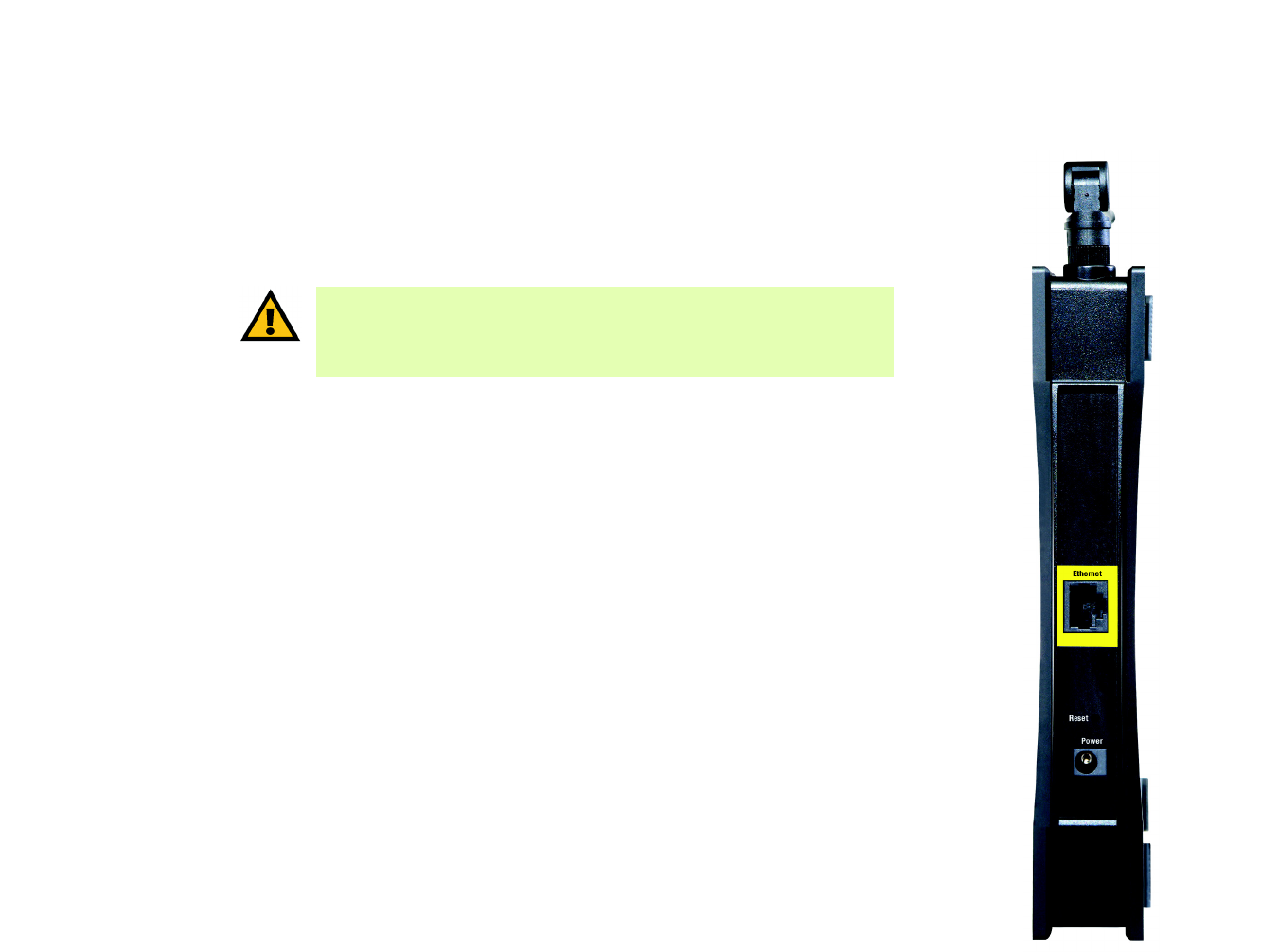
The Back Panel
The Access Point's Ethernet network and power ports, as well as the Reset button, are located on the back panel.
Ethernet Port The Ethernet network port connects to an Ethernet network device, such as a switch or router.
Reset Button There are two ways to Reset the Access Point's factory defaults. Either press the Reset
button, for approximately ten seconds, or restore the defaults using the Access Point's Web-
based Utility.
Power Port The Power port connects to the Access Point’s power adapter. (This port will not be used if you
are using Power Over Ethernet.)
Figure 3-2: Back Panel
port: the connection point on a computer or
networking device used for plugging in
cables or adapters
IMPORTANT: Resetting the Access Point will erase all of your settings
(including wireless security, IP address, and power output) and replace them
with the factory defaults. Do not reset the Access Point if you want to retain
these settings.

8
Chapter 4: Connecting the Wireless-G Access Point with Power Over Ethernet
Overview
Wireless-G Access Point with Power Over Ethernet
Chapter 4: Connecting the Wireless-G Access Point with
Power Over Ethernet
Overview
This chapter explains how to connect the Access Point for setups.
Connections for Setup
1. Attach the Access Point’s antenna.
2. Connect your Ethernet network cable to your network router or switch. Then connect the other end of the
network cable to the Access Point’s Ethernet port.
3. If you are using Power Over Ethernet (POE), proceed to the following section, “Placement Options.”
If you are not using POE, then connect the included power adapter to the Access Point’s Power port. Then
plug the power adapter into an electrical outlet. The LEDs on the front panel will light up as soon as the
Access Point’s powers on.
Proceed to the following section, “Placement Options.”
Figure 4-1: Connect the Ethernet Network Cable
Figure 4-2: Connect the Power
NOTE: The Bridge features Power Over
Ethernet (POE) support. POE technology allows
a POE adapter (also known as a power injector,
power hub, or inline power device) to supply
data and power to an Ethernet device using a
single Ethernet network cable. To use the
Bridge’s POE feature, follow the instructions
for your specific POE device.
9
Chapter 4: Connecting the Wireless-G Access Point with Power Over Ethernet
Placement Options
Wireless-G Access Point with Power Over Ethernet
Placement Options
There are three ways to place the Access Point. The first way is to place it horizontally on a surface, so it sits on
its four rubber feet. The second way is to stand the Access Point vertically on a surface. The third way is to mount
it on a wall. The stand and wall-mount options are explained in further detail below.
Stand Option
1. Near the Access Point’s bottom panel are two rubber feet and two rubber inserts. Remove them to expose the
stand slots you want to use.
2. The Access Point includes four triangular stands. With its rubber pad facing the bottom, insert a stand into a
slot, and push the stand upward until the stand snaps into place.
Repeat this step with the other stands.
Now that the hardware installation is complete, proceed to “Chapter 5: Setting Up the Wireless-G Access
Point with Power Over Ethernet,” for directions on how to configure the Access Point.
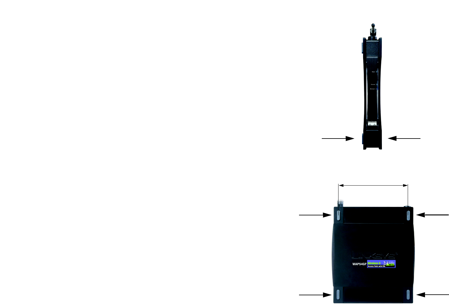
Wall-Mount Option
1. On one of the Access Point’s side panels are four rubber feet. Remove four adjacent feet to expose the wall-
mount slots you want to use. The distance between two adjacent slots is 145 mm (5.7 inches).
2. Determine where you want to mount the Access Point.
3. Drill four holes into the wall. Make sure adjacent holes are 145 mm (5.7 inches) apart.
4. Insert a screw into each hole, and leave 5 mm (0.2 inches) of its head exposed.
5. Maneuver the Router so the wall-mount slots line up with the four screws.
6. Place the wall-mount slots over the screws and slide the Access Point down until the screws fit snugly into
the wall-mount slots.
Now that the hardware installation is complete, proceed to “Chapter 5: Setting Up the Wireless-G Access
Point with Power Over Ethernet,” for directions on how to configure the Access Point.
Figure 4-4: The Access Point’s Wall-Mount Slots
Figure 4-3: The Access Point’s Stand Slots
145 mm
(5.7 inches)

10
Chapter 5: Setting Up the Wireless-G Access Point with Power Over Ethernet
Setup Wizard
Wireless-G Access Point with Power Over Ethernet
Chapter 5: Setting Up the Wireless-G Access Point with Power
Over Ethernet
Setup Wizard
Now that you've connected the Access Point to your wired network, you are ready to begin setting it up. This
Setup Wizard will take you through all the steps necessary to configure the Access Point.
1. Insert the Setup Wizard CD into your PC's CD-ROM drive. Your PC must be on your wired network to set up the
Access Point.
2. The Setup Wizard's Welcome screen should appear on your monitor. If it does not, then click the Start button
and select Run. In the field provided, enter D:\setup.exe (if “D” is the letter of your PC's CD-ROM drive).
Click the Click Here to Start or Setup button to proceed with this Setup Wizard. Clicking the User Guide
button opened this Guide. To exit this Setup Wizard, click the Exit button.
Figure 5-1: Setup Wizard’s Welcome Screen

11
Chapter 5: Setting Up the Wireless-G Access Point with Power Over Ethernet
Setup Wizard
Wireless-G Access Point with Power Over Ethernet
3. Optimally, you should set up the Access Point using a PC on your wired network. Connect a network cable to
your network switch or router. Click the Next button to continue or Back to return to the previous screen.
4. The screen shows how the Access Point should be connected as you run the Setup Wizard. Connect the other
end of the network cable to the Access Point. Click the Next button to continue or Back to return to the
previous screen.
Figure 5-3: Connect the Network Cable to the
Access Point
Figure 5-2: Connect the Network Cable to Your Switch
or Router
12
Chapter 5: Setting Up the Wireless-G Access Point with Power Over Ethernet
Setup Wizard
Wireless-G Access Point with Power Over Ethernet
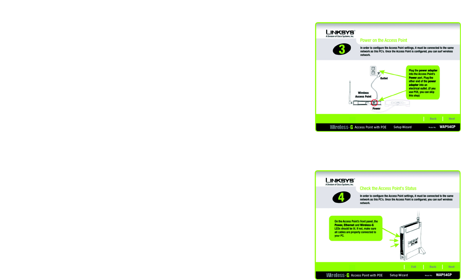
5. Connect the power adapter to the Access Point and an electrical outlet. (If you are using Power Over Ethernet,
(POE), then you can skip this step.) Click the Next button to continue or Back to return to the previous screen.
6. Make sure the Access Point’s Power and Wireless Link LEDs are lit. If they are not, check your cable
connections. Click the Next button to continue Click the Next button to continue or Back to return to the
previous screen. You can also click Exit to exit the Setup Wizard.
Figure 5-5: Check the Access Point’s Status
Figure 5-4: Power on the Access Point

13
Chapter 5: Setting Up the Wireless-G Access Point with Power Over Ethernet
Setup Wizard
Wireless-G Access Point with Power Over Ethernet
7. The Setup Wizard will run a search for the Access Point within your network and then display a list along with
the status information for the selected access point. If this is the only access point on your network, it will be
the only one displayed. If there are more than one displayed, select the Access Point by clicking on it. Then
click the Yes button to continue or No to exit the Setup Wizard.
8. You will be asked to sign onto the Access Point you have selected. Enter the default user name and password,
admin, in both fields. Then, click Enter. (This user name and password can be changed from the Web-based
Utility's Administration - Management tab.)
Figure 5-7: Login Screen
Figure 5-6: Select an Access Point
14
Chapter 5: Setting Up the Wireless-G Access Point with Power Over Ethernet
Setup Wizard
Wireless-G Access Point with Power Over Ethernet
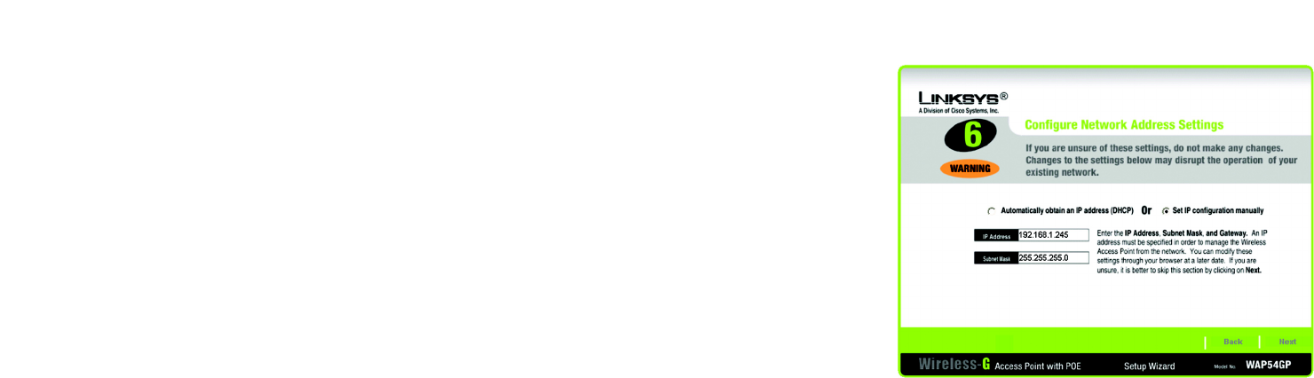
9. The Configure Network Address Settings screen will appear next. If your network router will automatically
assign an IP address to the Access Point, then select Automatically obtain an IP address (DHCP).
If you want to assign a static or fixed IP address to the Access Point, then select Set IP configuration
manually. Enter an IP Address and Subnet Mask.
Then, click the Next button to continue or Back to return to the previous page.
• IP Address. This IP address must be unique to your network. (The default IP address is 192.168.1.245.)
• Subnet Mask. The Access Point's Subnet Mask must be the same as the subnet mask of your Ethernet
network.
Figure 5-8: Configure Network Address Settings Screen
ip address: the address used to identify a computer
or device on a network.
ip (internet protocol): a protocol used to send data over
a network.
dhcp (dynamic host configuration protocol): a networking
protocol that allows administrators to assign temporary IP
addresses to network computers by “leasing” an IP address
to a user for a limited amount of time, instead of assigning
permanent IP addresses.
subnet mask: an address code that determines the
size of the network.

15
Chapter 5: Setting Up the Wireless-G Access Point with Power Over Ethernet
Setup Wizard
Wireless-G Access Point with Power Over Ethernet
10. The Wireless Settings screen should now appear. The Access Point can connect to up to eight wireless
networks at the same time. On this screen, you can configure up to three SSIDs, as well as the Access Point’s
channel setting and wireless mode. (To configure additional networks, then use the Web-based Utility.)
Select Main SSID and enter your primary SSID in the field provided.
Select the channel you want the Access Point to use for all of the wireless networks it supports.
Select the wireless mode you want the Access Point to use for all of the wireless networks it supports.
Select SSID1 and enter your second SSID in the field provided.
Select SSID2 and enter your third SSID in the field provided.
After you have entered the settings for your three wireless networks, click the Next button to continue or
Back to return to the previous page.
• SSID. The SSID is the unique name shared among all devices in a wireless network. It is case-sensitive
and must not exceed 32 characters, which may be any keyboard character. Make sure this setting is the
same for all devices in your wireless network.
• Channel. Select the appropriate channel from the list provided to correspond with your network settings.
All devices in your wireless network must use the same channel in order to communicate.
• Mode. Select Mixed Mode if you want both Wireless-G and Wireless-B computers allowed on the
networks, but note that the speed will be reduced. Select G-Only for maximum speed with Wireless-G
products only. The final selection, B-Only, allows only Wireless-B products on the networks. You can also
disable wireless performance if you select Disable.
Figure 5-9: Wireless Settings Screen
NOTE: The Access Point uses the same
channel setting and mode for all of the
wireless networks it supports.