LINKSYS WAP54GP Wireless-G Access Point with POE User Manual Book
LINKSYS LLC Wireless-G Access Point with POE Book
LINKSYS >
Contents
- 1. Users Manual 1
- 2. Users Manual 2
- 3. Users Manual 3
- 4. Users Manual 4
Users Manual 3
30
Chapter 6: Configuring the Wireless-G Access Point with Power Over Ethernet
The Wireless - Advanced Wireless Settings Tab
Wireless-G Access Point with Power Over Ethernet
The Wireless - Advanced Wireless Settings Tab
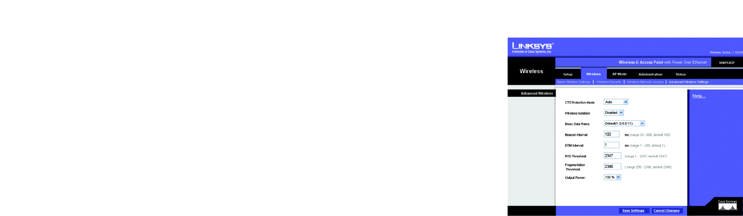
This screen allows you to configure the advanced settings for the Access Point. In most cases, these settings do
not need to be changed.
Advanced Wireless
You can change the data transmission and output power settings for the Access Point.
CTS Protection Mode. The CTS (Clear-To-Send) Protection Mode function boosts the Access Point’s ability to
catch all Wireless-G transmissions but will severely decrease performance. Keep the default setting, Auto, so the
Access Point can use this feature as needed, when the Wireless-G products are not able to transmit to the Access
Point in an environment with heavy 802.11b traffic. Select Enabled if you want to permanently enable this
feature, or select Disabled if you want to permanently disable this feature.
Wireless Isolation. When this feature is enabled, PCs using different SSIDs cannot see each other, so the
different wireless networks are kept separate from each other. In most cases, including wireless hotspots, keep
the default, Enabled. If you want PCs from different wireless networks to communicate, select Disabled.
Basic Data Rates. This setting is not actually one rate of transmission but a series of rates that are advertised to
the other wireless devices in your network, so they know at which rates the Access Point can transmit. At the
Default setting, the Access Point will advertise that it will automatically select the best rate for transmission.
Other options are 1-2Mbps, for use with older wireless technology, and All, when you wish to have all rates
advertised. The Basic Data Rates are not the rates transmitted; the rates transmitted can be configured through
the TX Rate setting on the Wireless - Basic Wireless Settings tab.
Beacon Interval. This value indicates the frequency interval of the beacon. A beacon is a packet broadcast by
the Access Point to keep the network synchronized. A beacon includes the wireless networks service area, the
Access Point address, the Broadcast destination addresses, a time stamp, Delivery Traffic Indicator Maps, and
the Traffic Indicator Message (TIM).
DTIM Interval. This value indicates how often the Access Point sends out a Delivery Traffic Indication Message
(DTIM). Lower settings result in more efficient networking, while preventing your PC from dropping into power-
saving sleep mode. Higher settings allow your PC to enter sleep mode, thus saving power, but interferes with
wireless transmissions.
RTS Threshold. This setting determines how large a packet can be before the Access Point coordinates
transmission and reception to ensure efficient communication. This value should remain at its default setting of
2347. Should you encounter inconsistent data flow, only minor modifications are recommended.
Figure 6-11: Wireless - Advanced Wireless
Settings Screen
cts (clear-to-send): a signal sent by a wireless device,
signifying that it is ready to receive data.
beacon internal: data transmitted on your wireless network
that keeps the network synchronized.
rts (request to send): a networking method of coordinating
large packets through the RTS Threshold setting.
dtim (delivery traffic indication message): a message
included in data packets that can increase wireless
efficiency.
packet: a unit of data sent over a network.

31
Chapter 6: Configuring the Wireless-G Access Point with Power Over Ethernet
The Wireless - Advanced Wireless Settings Tab
Wireless-G Access Point with Power Over Ethernet
Fragmentation Threshold. This specifies the maximum size a data packet can be before splitting and creating
a new packet. It should remain at its default setting of 2346. A smaller setting means smaller packets, which will
create more packets for each transmission. If you have decreased this value and experience high packet error
rates, you can increase it again, but it will likely decrease overall network performance. Only minor modifications
of this value are recommended.
Output Power. You can adjust the output power of the Access Point to get the appropriate coverage for your
wireless network. Select the level you need for your environment. If you are not sure which setting to choose,
then keep the default setting, 100%.
Change these settings as described here and click Save Settings to apply your changes, or click Cancel
Changes to cancel your changes. Click Help for more information.
fragmentation: breaking a packet into smaller units
when transmitting over a network.
32
Chapter 6: Configuring the Wireless-G Access Point with Power Over Ethernet
The AP Mode Tab
Wireless-G Access Point with Power Over Ethernet
The AP Mode Tab
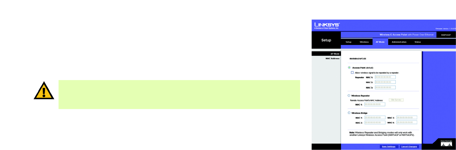
On this screen you can change the Access Point’s mode of operation. In most cases, you can keep the default,
Access Point. You may wish to do this if you want to use the Access Point as a wireless repeater to extend the
range of your wireless network. You may also wish to do this if you want to use the Access Point as a wireless
bridge; for example, you can use two Access Points in Wireless Bridge mode to connect two wired networks that
are in two different buildings.
AP Mode
The Access Point offers three modes of operation: Access Point, Wireless Repeater, and Wireless Bridge. For the
Repeater and Bridge modes, make sure the SSID, channel, and security settings are the same for the other
wireless access points/devices.
MAC Address
The MAC address of the Access Point is displayed here.
Access Point. The Mode is set to Access Point by default. This connects your wireless PCs to a wired network.
In most cases, no change is necessary.
If you want to let the Access Point’s signal be repeated, then click the checkbox next to Allow wireless signal to
be repeated by a repeater. Enter the MAC addresses of the repeaters in the MAC 1-3 fields. Repeaters can be
another access point or the Wireless-G Range Expander (model number: WRE54G).
Change these settings as described here and click Save Settings to apply your changes, or click Cancel
Changes to cancel your changes. Click Help for more information.
Figure 6-12: AP Mode Screen
IMPORTANT: For Wireless Repeater and Wireless Bridge modes, the remote access point must be a
second Linksys Wireless-G Access Point with Power Over Ethernet (model number: WAP54GP) or a
Linksys Wireless-G Exterior Access Point with Power Over Ethernet (model number: WAP54GPE). The
Access Point will not communicate with any other kind of remote access point.
33
Chapter 6: Configuring the Wireless-G Access Point with Power Over Ethernet
The AP Mode Tab
Wireless-G Access Point with Power Over Ethernet
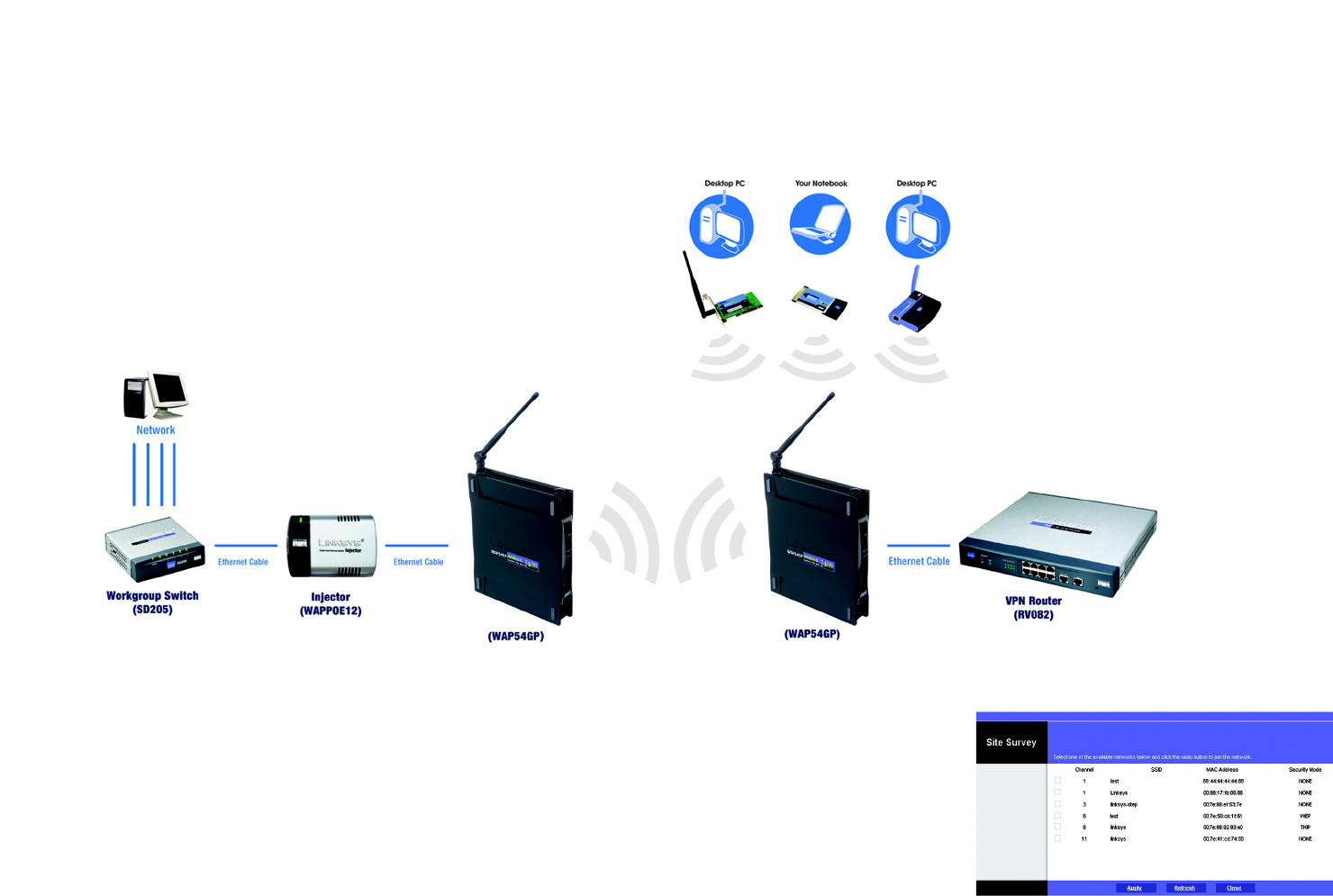
Wireless Repeater. When set to Wireless Repeater mode, the Wireless Repeater is able to talk to up a remote
access point within its range and retransmit its signal. This feature only works with the Linksys Wireless-G
Exterior Access Point with Power Over Ethernet (model number: WAG54GPE) or another Wireless-G Access Point
with Power Over Ethernet (model number: WAP54GP).
To configure a Wireless Repeater environment, select Wireless Repeater and enter the MAC address of the
remote access point in the MAC 1 field. If you do not know the access point’s MAC address, click the Site Survey
button. Select the access point you want to use and click the Apply button. Then click the Close button to return
to the AP Mode screen. If you do not see the access point you want, click the Refresh button to search for access
points again.
Change these settings as described here and click Save Settings to apply your changes, or click Cancel
Changes to cancel your changes. Click Help for more information.
Figure 6-13: Wireless Repeater Diagram
Figure 6-14: Site Survey Screen
34
Chapter 6: Configuring the Wireless-G Access Point with Power Over Ethernet
The AP Mode Tab
Wireless-G Access Point with Power Over Ethernet
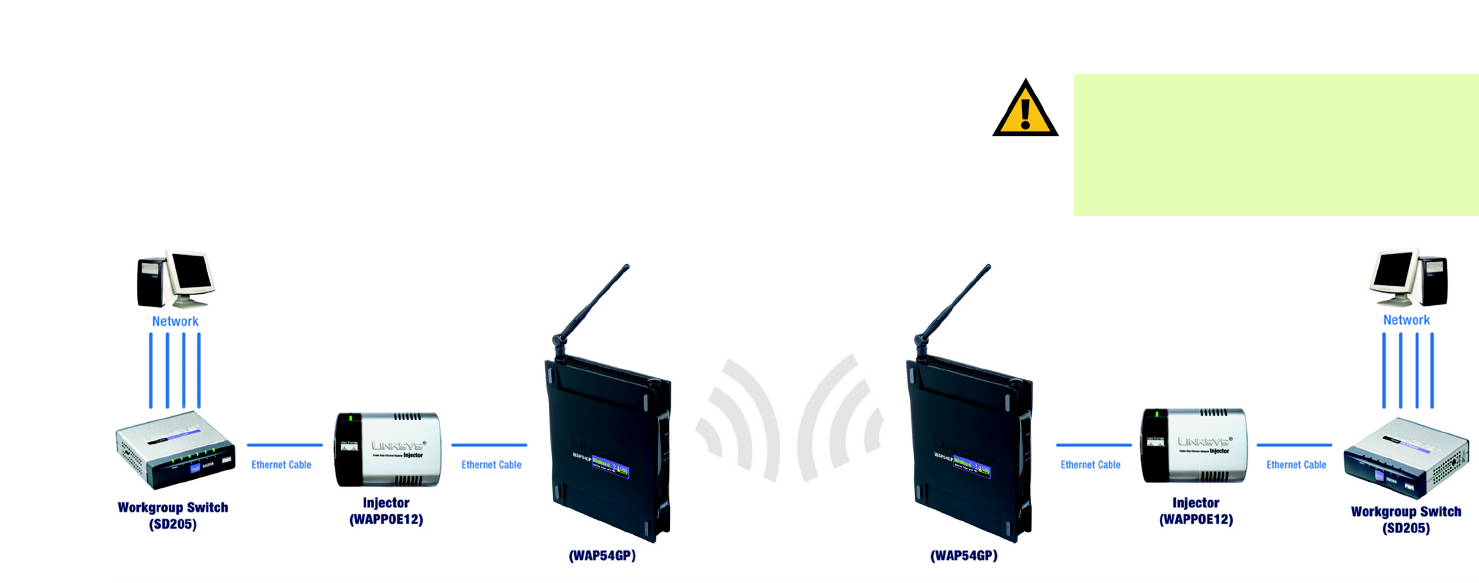
Wireless Bridge. This mode connects two physically separated wired networks using two access points (use
additional access points to connect more wired networks). This feature only works with the Linksys Wireless-G
Exterior Access Point with Power Over Ethernet (model number: WAG54GPE) or another Wireless-G Access Point
with Power Over Ethernet (model number: WAP54GP).
To configure a Wireless Bridge environment, select Wireless Bridge, and enter the MAC addresses of the
wireless bridges/access points in the MAC 1-4 fields. You will also need to set the remote wireless bridges/
access points to Wireless Bridge mode.
Change these settings as described here and click Save Settings to apply your changes, or click Cancel
Changes to cancel your changes. Click Help for more information.
IMPORTANT: In Wireless Bridge mode, the Access
Point can ONLY be accessed by another access point
in Wireless Bridge mode. In order for your other
wireless devices to access the Access Point, you
must reset it to Access Point mode. The two modes
are mutually exclusive.
Figure 6-15: Wireless Bridge Diagram

35
Chapter 6: Configuring the Wireless-G Access Point with Power Over Ethernet
The Administration - Management Tab
Wireless-G Access Point with Power Over Ethernet
The Administration - Management Tab
On this screen you can configure the password and SNMP settings.
AP Password
You should change the password that controls access to the Access Point’s Web-based Utility.
Local AP Password
User Name. Create a User Name and enter it in the field provided.
AP Password. Create a Password for the Access Point’s Web-based Utility.
Re-enter to confirm. To confirm the new Password, enter it again in this field.
Web Access
Web HTTPS Access. HTTPS (HyperText Transport Protocol Secure) uses SSL (Secured Socket Layer) to encrypt
data transmitted for higher security. To secure remote access of the Access Point’s Web-based Utility, select
Enabled. Otherwise, select Disabled.
SNMP
SNMP is a popular network monitoring and management protocol. It provides network administrators with the
ability to monitor the status of the Access Point and receive notification of any critical events as they occur on the
Access Point.
To enable the SNMP support feature, select Enabled. Otherwise, select Disabled.
Identification
Contact. Enter the name of the contact person, such as a network administrator, for the Access Point.
Device Name. Enter the name you wish to give to the Access Point.
Location. Enter the location of the Access Point.
Get Community. Enter the password that allows read-only access to the Access Point’s SNMP information. The
default is public.
Figure 6-16: Administration - Management Screen

36
Chapter 6: Configuring the Wireless-G Access Point with Power Over Ethernet
The Administration - Management Tab
Wireless-G Access Point with Power Over Ethernet
Set Community. Enter the password that allows read/write access to the Access Point’s SNMP information. The
default is private.
SNMP Trap-Community. Enter the password required by the remote host computer that will receive trap
messages or notices sent by the Access Point.
SNMP Trusted Host. You can restrict access to the Access Point’s SNMP information by IP address. Enter the IP
address in the field provided. If this field is left blank, then access is permitted from any IP address.
SNMP Trap-Destination. Enter the IP address of the remote host computer that will receive the trap messages.
Change these settings as described here and click Save Settings to apply your changes, or click Cancel
Changes to cancel your changes. Click Help for more information.

37
Chapter 6: Configuring the Wireless-G Access Point with Power Over Ethernet
The Administration - Log Tab
Wireless-G Access Point with Power Over Ethernet
The Administration - Log Tab
On this screen you can configure the log settings, as well as options for e-mail alerts of particular events.
Log
You can have logs that keep track of the Access Point’s activities.
Email Alert
E-Mail Alert. To receive e-mail alerts when certain events occur, select Enabled. Otherwise, select Disabled.
E-Mail Address for Logs. Enter the e-mail address that will receive the alert logs.
Notification Queue Length
Log Queue Length. Designate the length of the log that will be e-mailed to you. The default is 20 entries.
Log Time Threshold. Designate how often the log will be e-mailed. The default is 600 seconds (10 minutes).
Syslog Notification
Syslog is a protocol used to capture information about network activity. The Access Point supports this protocol
and send its activity logs to an external server. To enable Syslog, select Enabled. Otherwise, select Disabled.
Syslog Server IP Address. Enter the IP address of the Syslog server. In addition to the standard event log, the
Access Point can send a detailed log to an external Syslog server. The Access Point’s Syslog captures all log
activities and includes information about all data transmissions.
Log
Unauthorized Login Attempt. To receive alert logs about any unauthorized login attempts, click the checkbox.
System Error Messages. If you want to log system error messages, click the checkbox.
Authorized Login. If you want to log authorized logins, click the checkbox.
Configuration Changes. If you want to log any configuration changes, click the checkbox.
Change these settings as described here and click Save Settings to apply your changes, or click Cancel
Changes to cancel your changes. Click Help for more information.
Figure 6-17: Administration - Log Screen

38
Chapter 6: Configuring the Wireless-G Access Point with Power Over Ethernet
The Administration - Factory Default Tab
Wireless-G Access Point with Power Over Ethernet
The Administration - Factory Default Tab
On this screen you can restore the Access Point’s factory default settings.
Factory Default
Write down any custom settings before you restore the factory defaults. Once the Access Point is reset, you will
have to re-enter all of your configuration settings.
Restore Factory Defaults. To restore the Access Point's factory default settings, click the Yes radio button.
Otherwise, click the No radio button.
Change these settings as described here and click Save Settings to apply your changes, or click Cancel
Changes to cancel your changes. Click Help for more information.
The Administration - Firmware Upgrade Tab
On this screen you can upgrade the Access Point’s firmware. Do not upgrade the firmware unless you are
experiencing problems with the Access Point or the new firmware has a feature you want to use.
Firmware Upgrade
Before you upgrade the Access Point’s firmware, write down all of your custom settings. After you upgrade its
firmware, you will have to re-enter all of your configuration settings. To upgrade the Access Point’s firmware:
1. Download the firmware upgrade file from the Linksys website, www.linksys.com.
2. Extract the firmware upgrade file on your computer.
3. On the Firmware Upgrade screen, enter the location of the firmware upgrade file in the field provided, or click
the Browse button to find the file.
4. Click the Upgrade button, and follow the on-screen instructions.
Click Help for more information.
Figure 6-19: Administration - Firmware Upgrade Screen
Figure 6-18: Administration - Factory Default Screen
upgrade: to replace existing software or
firmware with a newer version

39
Chapter 6: Configuring the Wireless-G Access Point with Power Over Ethernet
The Administration - Language Upgrade Tab
Wireless-G Access Point with Power Over Ethernet
The Administration - Language Upgrade Tab
On this screen you can do a language upgrade to change the language used by the Access Point’s Web-based
Utility.
Language Upgrade
If you do want to change the language currently used by the Web-based Utility, then you can download a
language upgrade file and update the Access Point.
To change the Access Point’s language:
1. Download the language upgrade file from the Linksys website, www.linksys.com.
2. Extract the language upgrade file on your computer.
3. On the Language Upgrade screen, enter the location of the language upgrade file in the field provided, or click
the Browse button to find the file.
4. Click the Upgrade button, and follow the on-screen instructions.
Click Help for more information.
The Administration - Reboot Tab
On this screen you can reboot the Access Point.
Reboot
This feature is useful when you need to remotely reboot the Access Point.
Device Reboot. To reboot the Access Point, click the Yes radio button. Otherwise, click the No radio button.
Change these settings as described here and click Save Settings to apply your changes, or click Cancel
Changes to cancel your changes. Click Help for more information.
Figure 6-20: Administration - Language Upgrade Screen
Figure 6-21: Administration - Reboot Screen
NOTE: Not all languages are available. Check
the Linksys website for available language
upgrade files.

40
Chapter 6: Configuring the Wireless-G Access Point with Power Over Ethernet
The Administration - Config Management Tab
Wireless-G Access Point with Power Over Ethernet
The Administration - Config Management Tab
On this screen you can create a backup configuration file or save a configuration file to the Access Point.
Config Management
Use this screen to upload or download configuration files for the Access Point.
Download AP Config. To save a backup configuration file on a computer, click the Download AP Configuration
File button and follow the on-screen instructions.
Upload AP Config. To upload a configuration file to the Access Point, enter the location of the configuration file in
the field provided, or click the Browse button to find the file. Then click the Load button.
Click Help for more information.
Figure 6-22: Administration - Config
Management Screen

41
Chapter 6: Configuring the Wireless-G Access Point with Power Over Ethernet
The Status - Local Network Tab
Wireless-G Access Point with Power Over Ethernet
The Status - Local Network Tab
The Local Network screen displays the Access Point’s current status information for the local network.
Information
Hardware Version. This is the version of the Access Point’s current hardware.
Software Version. This is the version of the Access Point’s current software.
Local MAC Address. The MAC address of the Access Point’s Local Area Network (LAN) interface is displayed
here.
System Up Time. This is the length of time the Access Point has been running.
Local Network
IP Address. This shows the Access Point’s IP Address, as it appears on your local network.
Subnet Mask. This shows the Access Point’s Subnet Mask.
Default Gateway. Displayed here is the IP address of the Access Point’s Default Gateway.
Primary and Secondary DNS. DNS addresses used by the Access Point are displayed here.
To update the status information, click the Refresh button. Click Help for more information.
Figure 6-23: Status - Local Network Screen

42
Chapter 6: Configuring the Wireless-G Access Point with Power Over Ethernet
The Status - Wireless Tab
Wireless-G Access Point with Power Over Ethernet
The Status - Wireless Tab
The Wireless screen displays the Access Point’s current status information for the wireless network(s).
Wireless Network
MAC Address. The MAC Address of the Access Point’s wireless interface is displayed here.
Mode. The Access Point’s mode is displayed here.
SSID. The Access Point’s main SSID is displayed here.
Virtual SSID1-7. The Access Point’s virtual SSIDs are displayed here.
Channel. The Access Point’s Channel setting for wireless broadcast is shown here.
VLAN Trunk. The status of the Access Point’s VLAN feature is shown here.
Priority Setting. The VLAN Priority Setting for the main SSID is shown here.
SSID Encryption Function. The wireless security setting for the main SSID is displayed here.
SSID Priority. The VLAN Priority setting for the main SSID is displayed here.
Virtual SSID1-7 Encryption Function. The wireless security settings for the virtual SSIDs are displayed here.
Virtual SSID1-7 Priority. The VLAN Priority settings for the virtual SSIDs are displayed here.
To update the status information, click the Refresh button. Click Help for more information.
Figure 6-24: Status - Wireless Screen

43
Chapter 6: Configuring the Wireless-G Access Point with Power Over Ethernet
The Status - System Performance Tab
Wireless-G Access Point with Power Over Ethernet
The Status - System Performance Tab
The System Performance screen displays the Access Point’s status information for its current settings and data
transmissions.
System Performance
Wired
Name. This indicates that the statistics are for the wired network, the LAN.
IP Address. The Access Point’s local IP address is displayed here.
MAC Address. This shows the MAC Address of the Access Point’s wired interface.
Connection. This shows the status of the Access Point’s connection for the wired network.
Packets Received. This shows the number of packets received.
Packets Sent. This shows the number of packets sent.
Bytes Received. This shows the number of bytes received.
Bytes Sent. This shows the number of bytes sent.
Error Packets Received. This shows the number of error packets received.
Dropped Packets Received. This shows the number of dropped packets received.
Wireless
Name. This indicates which wireless network/SSID to which the statistics refer.
IP Address. The Access Point’s local IP address is displayed here.
MAC Address. This shows the MAC Address of the Access Point’s wireless interface.
Connection. This shows the status of the Access Point’s connection for each wireless network.
Packets Received. This shows the number of packets received for each wireless network.
Packets Sent. This shows the number of packets sent for each wireless network.
Figure 6-25: Status - System Performance Screen

44
Chapter 6: Configuring the Wireless-G Access Point with Power Over Ethernet
The Status - System Performance Tab
Wireless-G Access Point with Power Over Ethernet
Bytes Received. This shows the number of bytes received for each wireless network.
Bytes Sent. This shows the number of bytes sent for each wireless network.
Error Packets Received. This shows the number of error packets received for each wireless network.
Dropped Packets Received. This shows the number of dropped packets received for each wireless network.
To update the status information, click the Refresh button. Click Help for more information.