LINKSYS WAP54GP Wireless-G Access Point with POE User Manual Book
LINKSYS LLC Wireless-G Access Point with POE Book
UserManual.wiki
>
LINKSYS
>
WAP54GP User Manual
>
Users Manual 3
Contents
1.
Users Manual 1
2.
Users Manual 2
3.
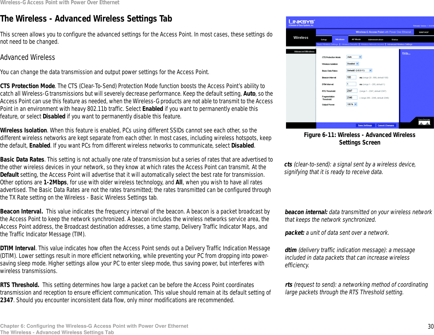
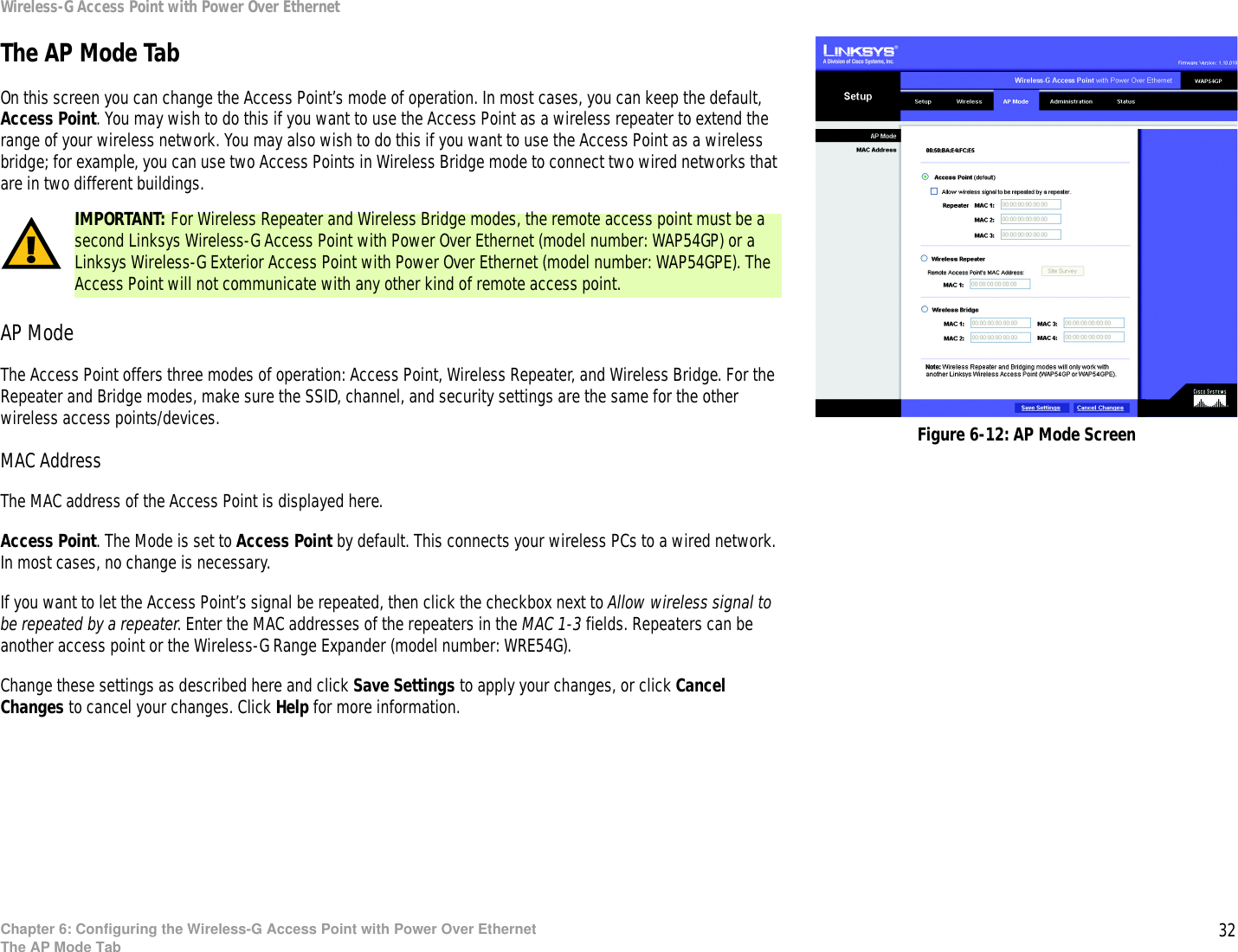
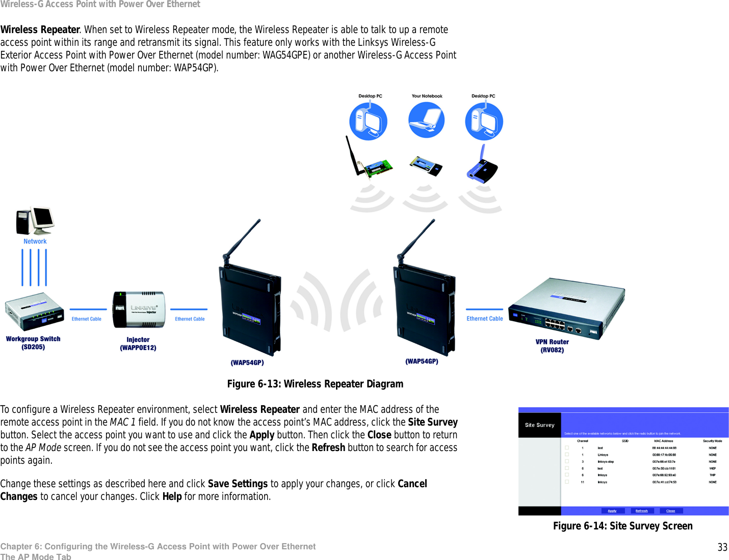
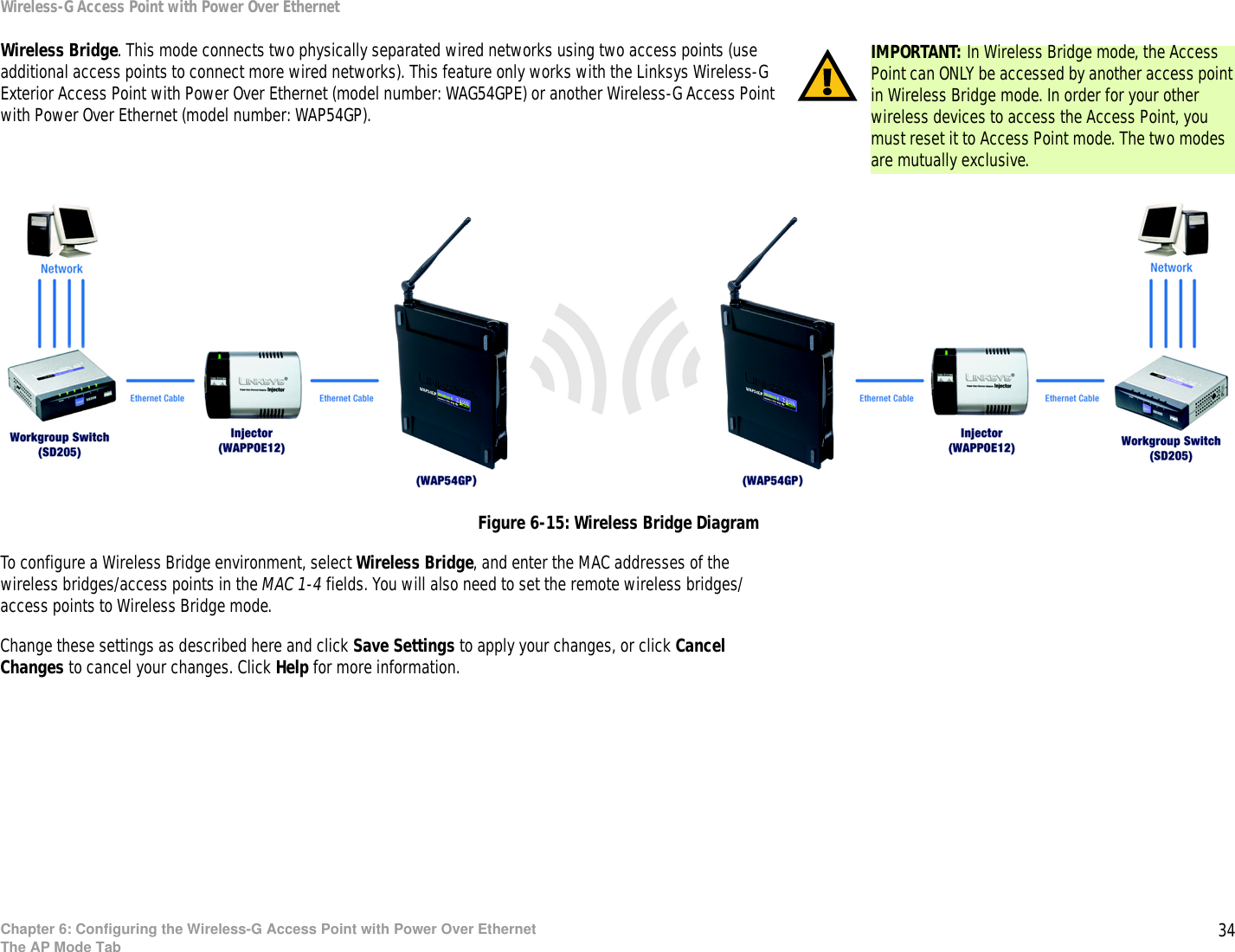
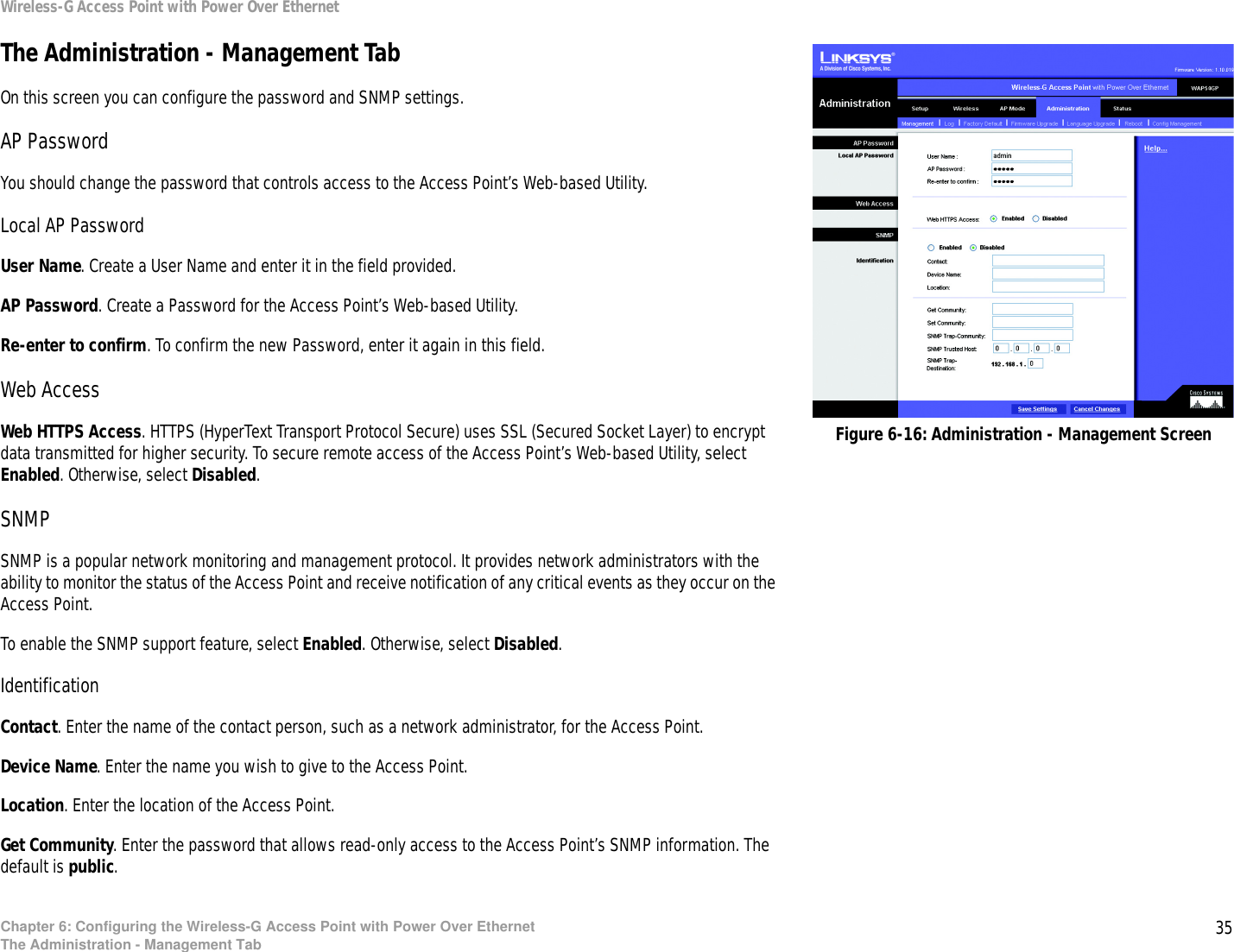
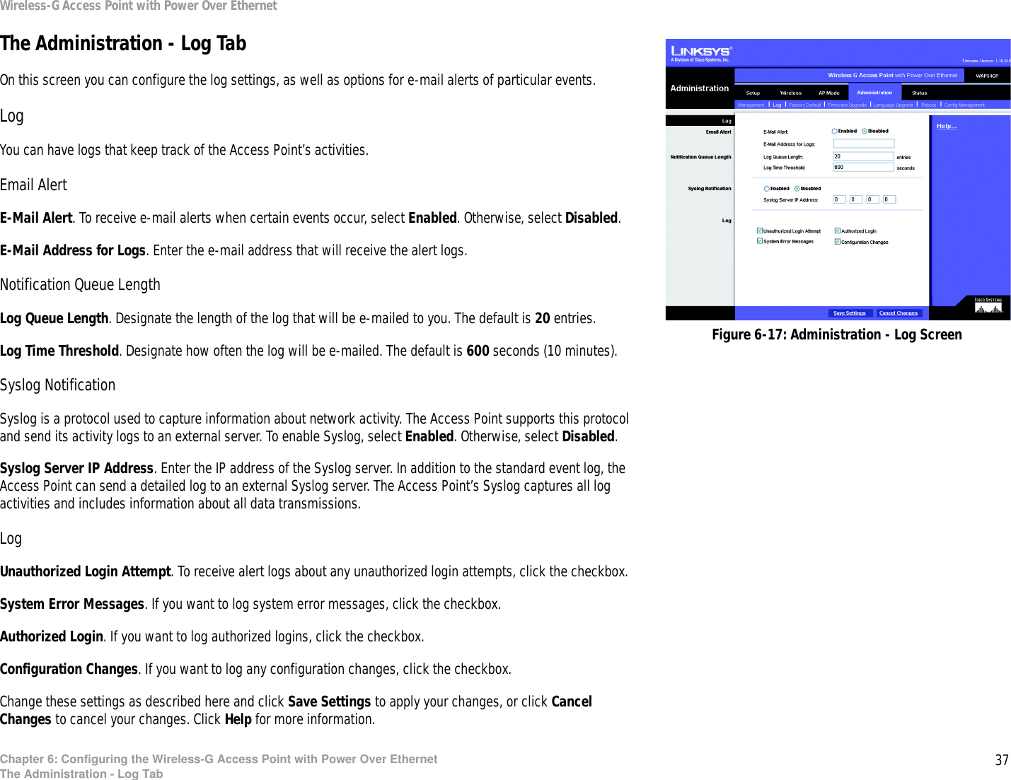
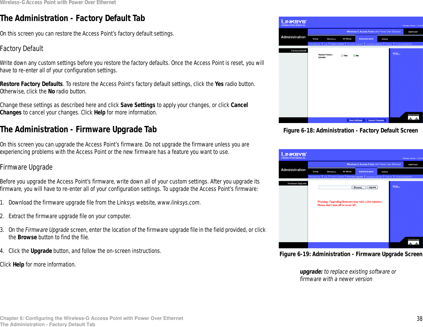
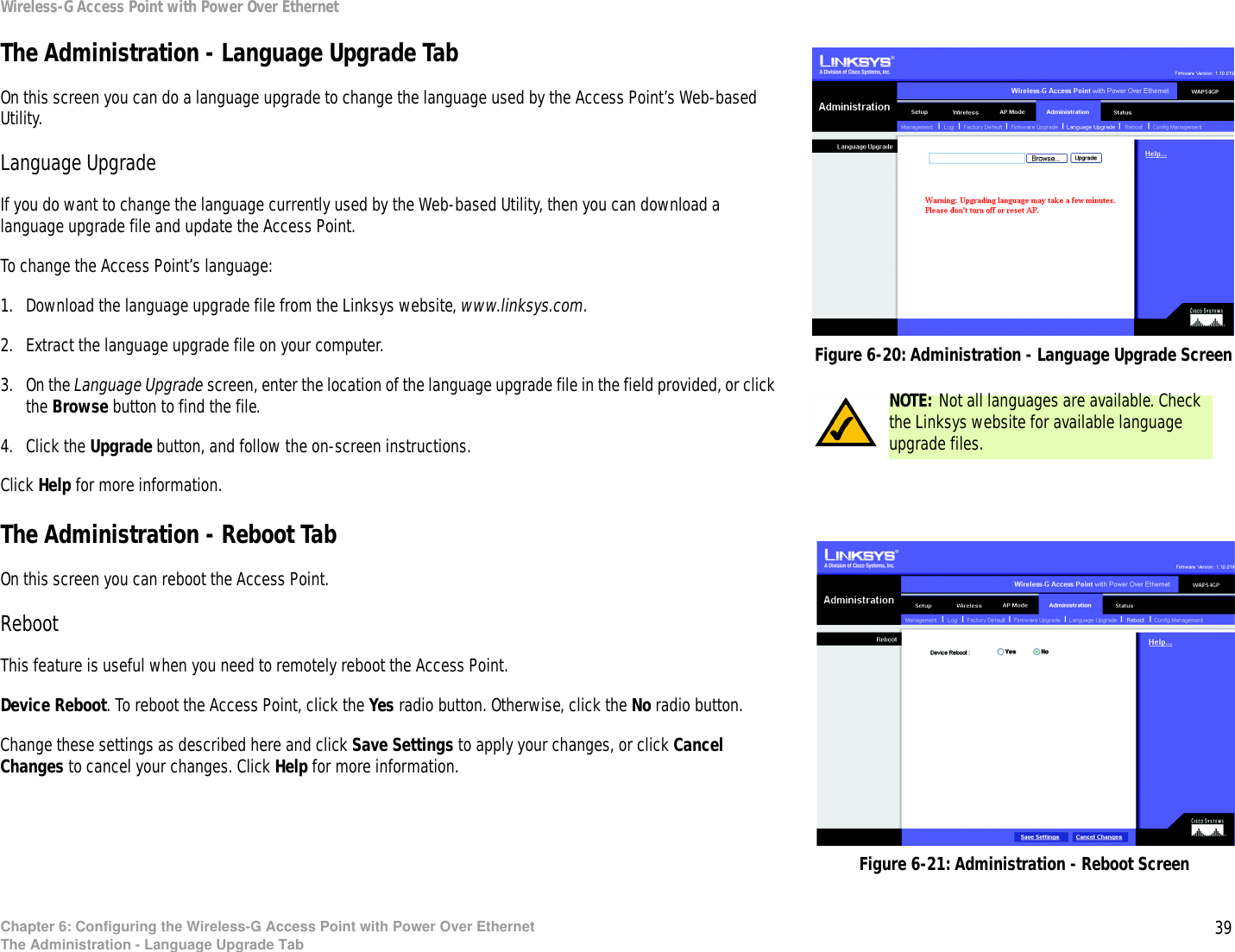
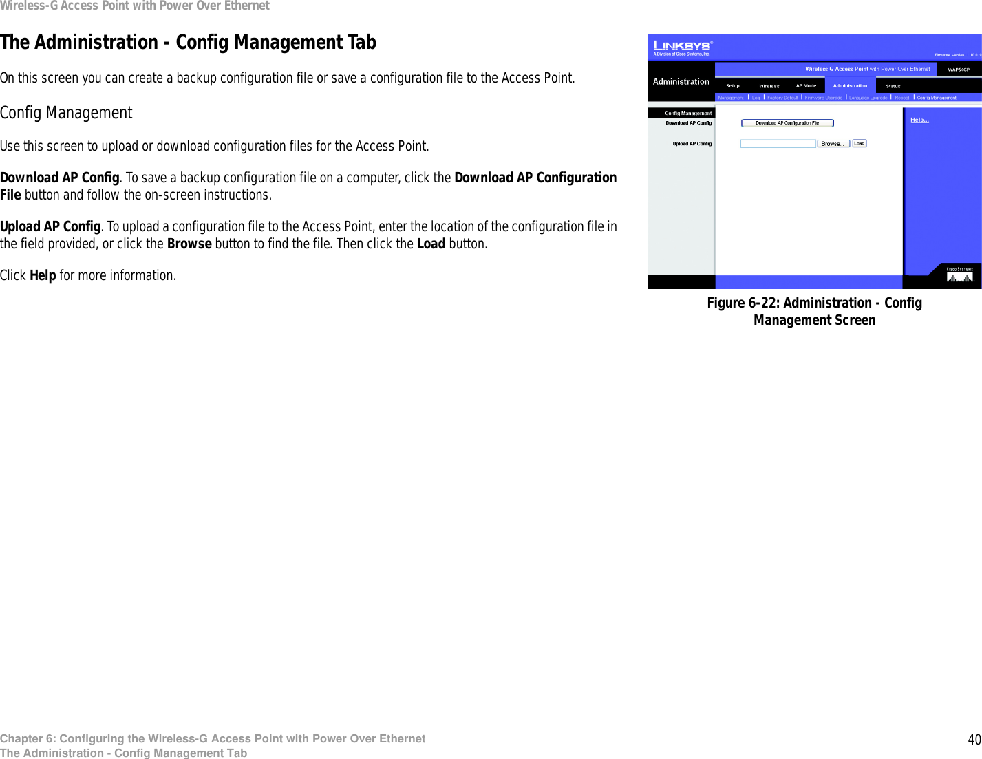
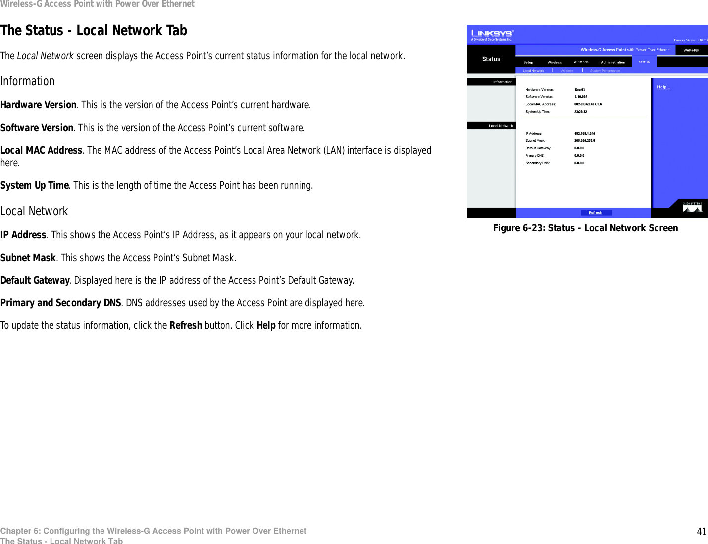
Users Manual 3
4.
Users Manual 4
Users Manual 3
Navigation menu
Upload a User Manual
Namespaces
Wiki Guide
HTML
PDF
Info
Views
User Manual
Discussion / Help
Navigation