LINKSYS WVC54GV1 Wireless-G Video Camera User Manual Book
LINKSYS LLC Wireless-G Video Camera Book
LINKSYS >
Part 2
13
Chapter 5: Setting up and Mounting the Wireless-G Internet Video Camera
Setup Wizard
Wireless-G Internet Video Camera
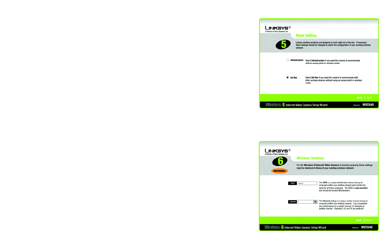
9. The Mode Setting screen will appear. Click the Infrastructure radio button if you want the Camera to
communicate using an access point or wireless router. Click the Ad-Hoc radio button if you want the Camera
to communicate without using an access point or wireless router. Click the Next button.
10. The Wireless Settings screen will appear, so you can change the wireless settings. Enter your wireless
network’s SSID or network name. If you chose Ad-Hoc mode, select the channel at which the network
broadcasts its wireless signal.
•SSID. The SSID must be identical for all devices in a wireless network. It is case-sensitive and should
have 32 alphanumeric characters or fewer. (You can use any keyboard character, but do not use any
spaces.)
•Channel. If you set the Camera to Ad-Hoc mode, select the appropriate channel from the drop-down
menu. All devices in your wireless ad-hoc network must use the same channel in order to function
correctly.
Then click the Next button.
Figure 5-8: Mode Settings Screen
Figure 5-9: Wireless Settings Screen
14
Chapter 5: Setting up and Mounting the Wireless-G Internet Video Camera
Setup Wizard
Wireless-G Internet Video Camera
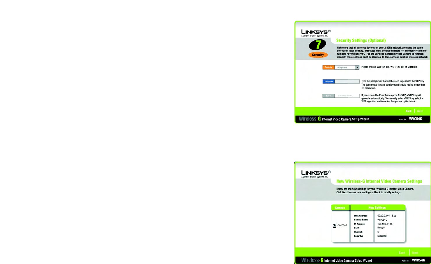
11. The Security Settings screen will appear. If your network has WEP encryption enabled, then select the level of
WEP encryption and enter a Passphrase. If you want to manually enter a WEP key, leave the Passphrase field
blank, and enter the WEP key in the Key 1 field. If your network doesn’t have WEP encryption disabled, keep
the default, Disabled.
•WEP. To enable WEP encryption, select 64-Bit Keys or 128-Bit Keys from the drop-down menu. Then
enter a Passphrase. If you want to manually enter a WEP key, leave the Passphrase field blank.
•Passphrase. If you enabled WEP encryption, you can enter a Passphrase, so a WEP key will be
automatically generated. If you want to manually enter a WEP key, leave the Passphrase field blank. The
Passphrase is case-sensitive and should have 16 alphanumeric characters or fewer. It must match the
passphrase of your wireless network and is compatible with Linksys wireless products only. (You will
have to enter the WEP key(s) manually on any non-Linksys wireless products.)
•Key 1. If you want to manually enter a WEP key, complete this field. If you are using 64-bit WEP
encryption, then the key must consist of exactly 10 hexadecimal characters. If you are using 128-bit WEP
encryption, then the key must consist of 26 hexadecimal characters. Valid hexadecimal characters are
“0” through “9” and “A” through “F”.
Click the Next button.
12. Review your settings before the Setup Wizard starts to copy your files. Click the Next button to continue.
Figure 5-10: Security Settings Screen
Figure 5-11: Review New Settings Screen
15
Chapter 5: Setting up and Mounting the Wireless-G Internet Video Camera
Setup Wizard
Wireless-G Internet Video Camera
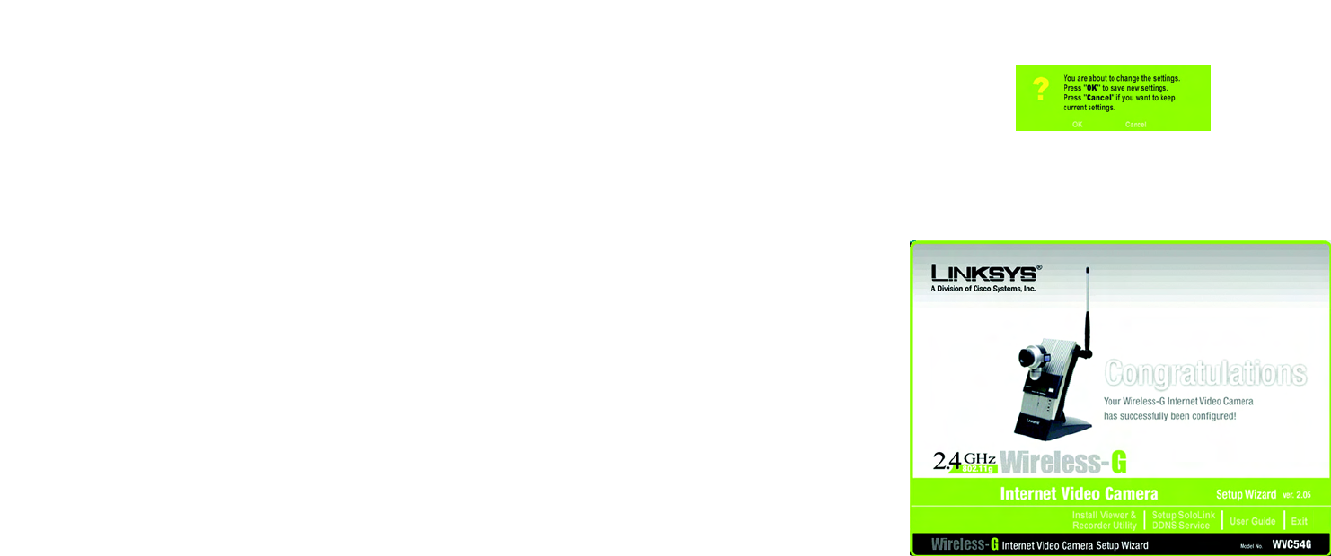
13. If you want to save the new settings, click the OK button. If you want to cancel your changes, click the Cancel
button.
14. After the files have been successfully copied, the Congratulations screen will appear.
•Install Viewer & Recorder Utility. Click this button to install the Camera’s Utility on your PC.
•Setup SoloLink DDNS Service. Click the Setup SoloLink DDNS Service button to set up and configure
the Linksys Dynamic Domain Name System (DDNS) service.
•Exit. Click the Exit button if you want to install the Camera’s Utility later.
Go to the “Placement Options” section.
Figure 5-13: Congratulations Screen
Figure 5-12: Confirmation Screen
16
Chapter 5: Setting up and Mounting the Wireless-G Internet Video Camera
Placement Options
Wireless-G Internet Video Camera
Placement Options
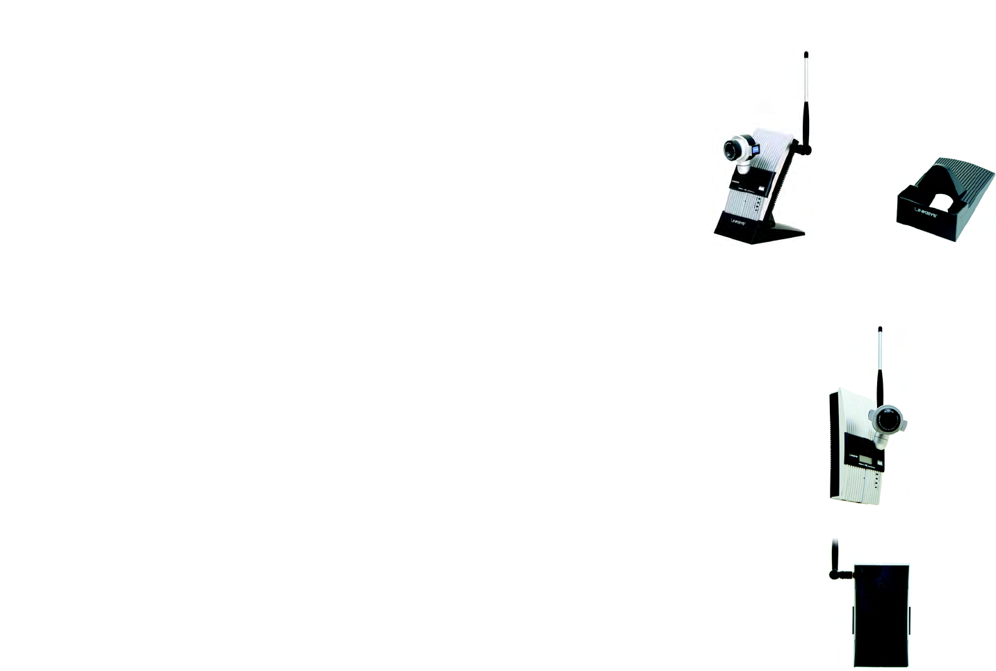
There are three ways to place the Camera. The first way is to place the Camera horizontally on a surface, so it sits
on four small rubber feet. The second way is to stand the Camera vertically on a surface (see Figure 5-14). The
third way is to hang the Camera on a wall (see Figure 5-16). The second and third options are explained in further
detail below.
Stand Option
1. The Camera includes a Camera Desktop Stand. Insert the bottom end into the Stand.
2. Place the Camera, and adjust its aim and focus accordingly.
Wall Mount Option
The Camera has two wall-mount slots on its back panel. The distance between the slots is 80 mm (3.15 inches).
1. Determine where you want to mount the Camera. Attach two screws to the wall, so that the Switch’s wall-
mount slots line up with the two screws.
2. Maneuver the Camera so the screws are inserted into the two slots.
3. Adjust the Camera’s aim and focus accordingly.
Proceed to the next section, “Audio Option.”
Audio Option
If you want to use your own microphone instead of the Camera’s built-in microphone, then follow these
instructions:
1. Connect the 2.5 mm input jack of your microphone to the Camera’s MIC IN port on its bottom panel. The built-
in microphone will automatically be disabled.
2. Place the external microphone in an appropriate location.
The installation of the Wireless-G Internet Video Camera is complete. Go to “Chapter 6: Installing the
Wireless-G Internet Video Camera Viewer & Recorder Utility.”
If advanced users wish to access the Camera through its Web-based Utility, then proceed to “Chapter 8:
Using the Wireless-G Internet Video Camera Web-based Utility.”
Figure 5-16: Wall Mount Option
Figure 5-14: Stand Option
Figure 5-17: Wall-Mount Slots
Figure 5-15: Camera
Desktop Stand
17
Chapter 6: Installing and Using the Wireless-G Internet Video Camera Viewer & Recorder Utility
Overview
Wireless-G Internet Video Camera
Chapter 6: Installing and Using the Wireless-G Internet Video
Camera Viewer & Recorder Utility
Overview
This chapter will instruct you on how to install and use the Wireless-G Internet Video Camera Viewer & Recorder
Utility on your PC. The Utility allows you to easily view and record the Camera’s video.
If the Wireless-B Internet Video Camera Viewer & Recorder Utility has already been installed on your PC, Linksys
recommends that you uninstall it before you install the Wireless-G Internet Video Camera Viewer & Recorder
Utility (this Utility will also work with Wireless-B Internet Video Cameras).
Installing the Viewer & Recorder Utility
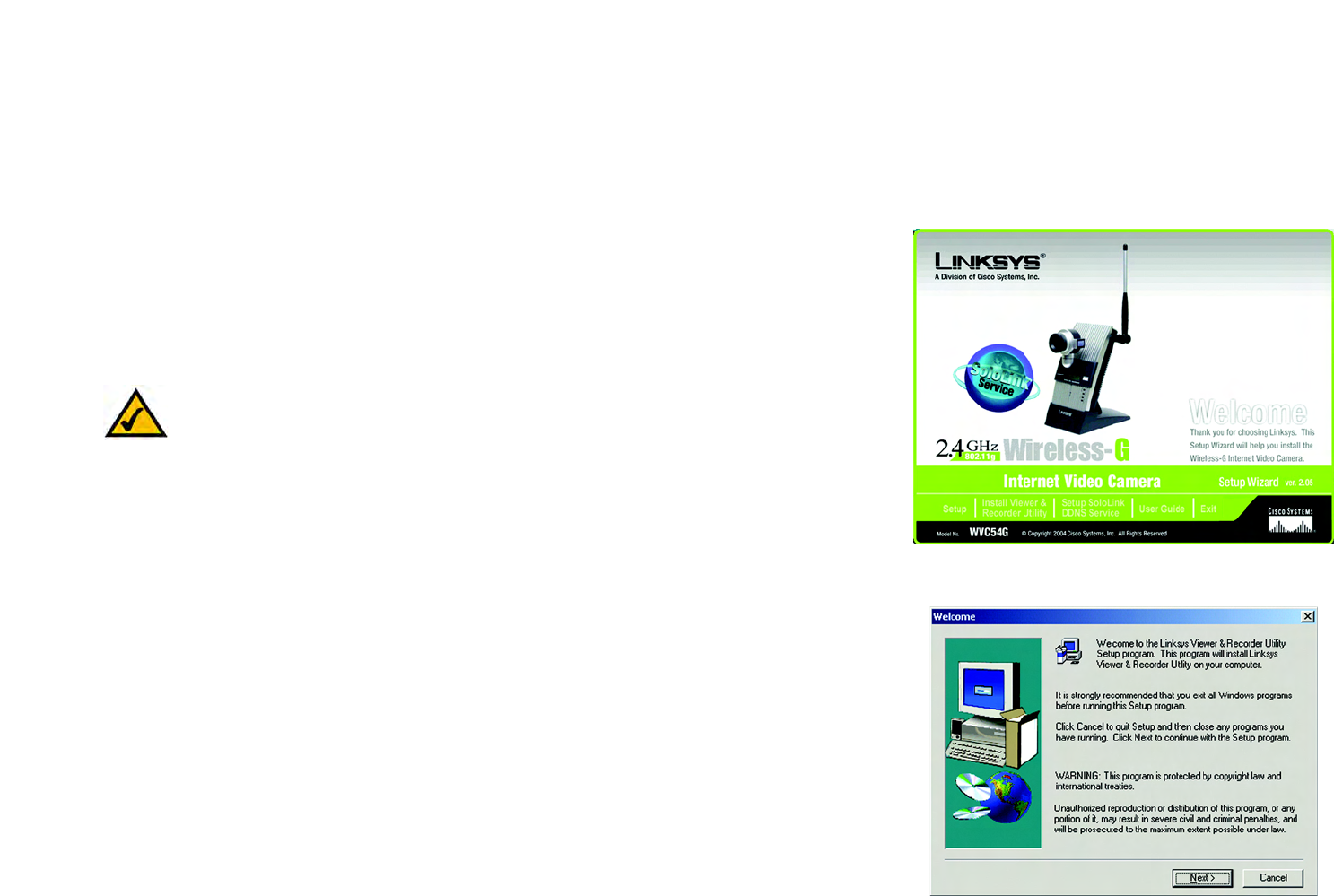
1. On the Welcome or Congratulations screen of the Setup Wizard, click the Install Viewer & Recorder Utility
button.
2. The Welcome screen will appear. Click the Next button to proceed.
Figure 6-1: Install Viewer & Recorder Utility Screen
Figure 6-2: Install Viewer & Recorder Utility -
Welcome Screen
NOTE: To view video using a web browser, you must use Internet Explorer version 5.5 or higher. The
View Video feature will not work with Netscape. Netscape users should use the Viewer & Recorder
Utility instead.
18
Chapter 6: Installing and Using the Wireless-G Internet Video Camera Viewer & Recorder Utility
Installing the Viewer & Recorder Utility
Wireless-G Internet Video Camera
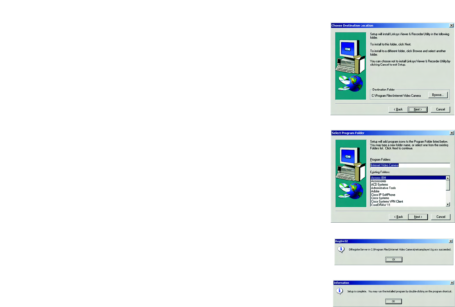
3. The Choose Destination Location screen will appear. To install the Viewer & Recorder Utility files in the default
folder, click the Next button. To select a different folder, click the Browse button and follow the on-screen
directions.
4. The Select Program Folder screen will appear. To add program icons to the default folder, click the Next
button. If you wish, you can rename the default folder. To add program icons to an existing folder, select one
from the Existing Folders listed, and then click the Next button.
5. After the OCX plug-in for video streaming has been installed, the screen shown in Figure 6-5 will appear. Click
the OK button.
6. When the setup is complete, click the OK button.
To learn how to use the Viewer & Recorder Utility, proceed to the next section, “Using the Viewer &
Recorder Utility.”
To set up the Linksys SoloLink Service, go to “Chapter 7: Setting up the Linksys SoloLink DDNS Service.”
Advanced users: If you want to use the Camera’s Web-based Utility, go to “Chapter 8: Using the
Wireless-G Internet Video Camera Web-based Utility.”
Figure 6-3: Choose Destination Location Screen
Figure 6-4: Select Program Folder Screen
Figure 6-5: OCX Plug-in Screen
Figure 6-6: Setup Complete Screen
19
Chapter 6: Installing and Using the Wireless-G Internet Video Camera Viewer & Recorder Utility
Using the Viewer & Recorder Utility
Wireless-G Internet Video Camera
Using the Viewer & Recorder Utility
After the Viewer & Recorder Utility has been installed, the Viewer & Recorder Utility icon will be displayed in two
locations, one on your desktop and one in the system tray of your desktop’s taskbar.
There are two ways to open the Viewer & Recorder Utility:
• Double-click the icon on your desktop (the icon acts as a shortcut)
• Right-click the icon in the system tray, and then click Main Program.
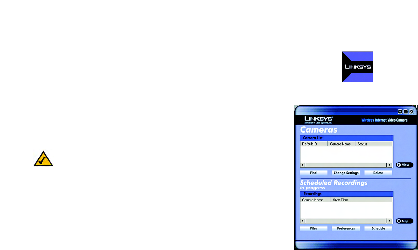
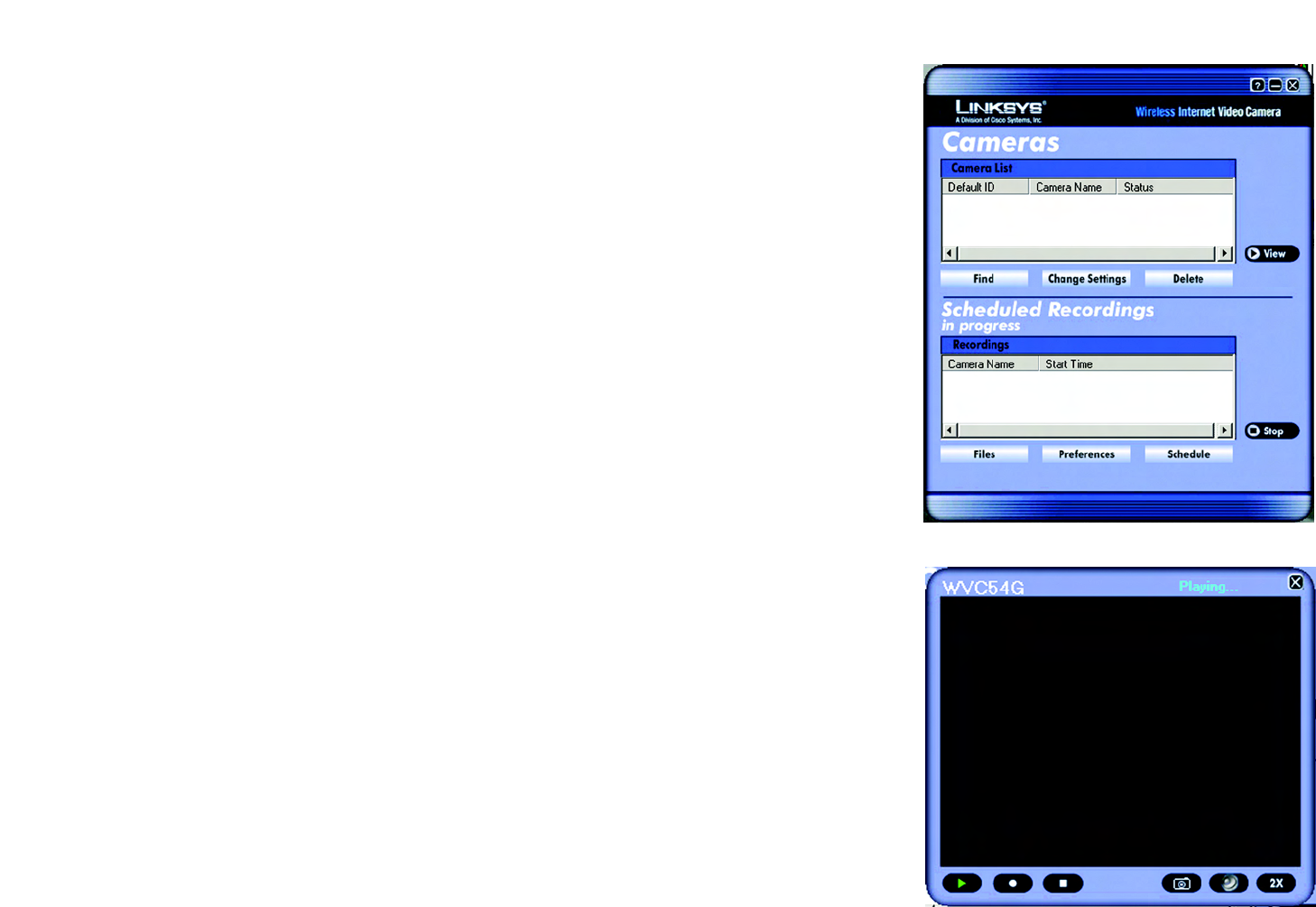
You will see the Utility’s main screen (see Figure 6-8).
It is divided into two sections, Cameras and Scheduled Recordings in progress. From this screen, you can control
Cameras, view video, and schedule recordings.
To minimize any of the Utility’s screens, click the X button in the upper right-hand corner. To request help
information, click the ? button in the upper right-hand corner. To close the Utility, right-click the Viewer &
Recorder Utility icon in your desktop’s system tray. Then click Exit.
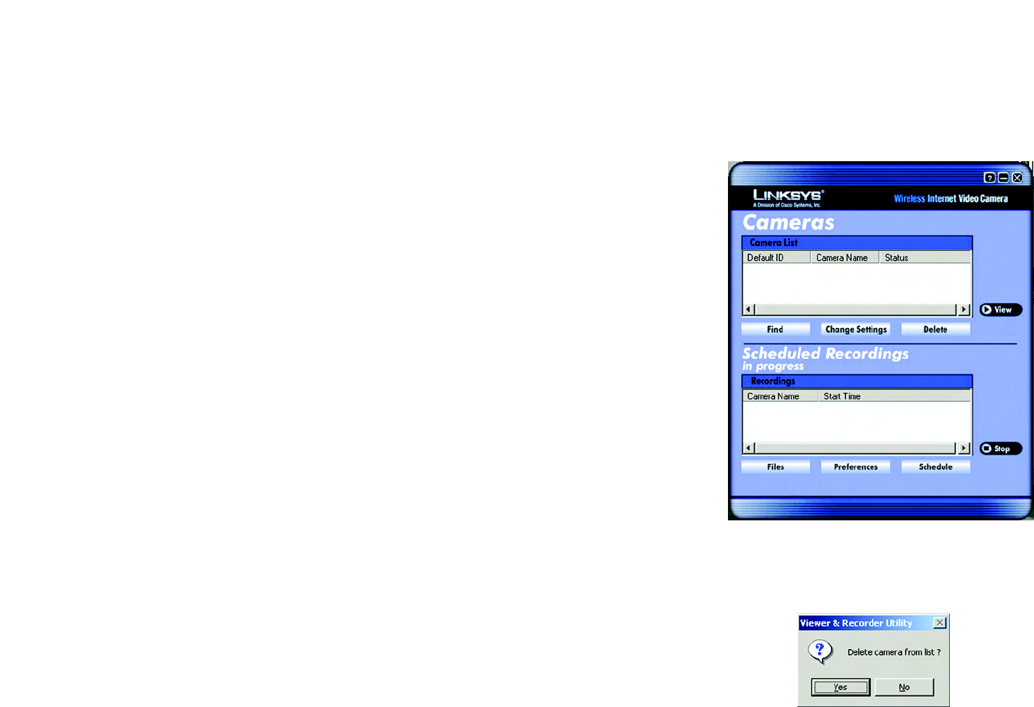
Cameras
From the Cameras section, you can find or delete Cameras, change Camera settings, and view current video.
Camera List
Default ID. The identification name of the Camera used by the Camera and the Utility to exchange data.
Camera Name. The name you gave to the Camera.
Status. The status of the Camera.
Figure 6-7: Viewer & Recorder Utility Icon
Figure 6-8: Main Screen
NOTE: This Viewer & Recorder Utility is backward-compatible with the Wireless-B Internet Video
Camera, so you can use this Utility to control Wireless-G and Wireless-B Internet Video Cameras on
your network.
20
Chapter 6: Installing and Using the Wireless-G Internet Video Camera Viewer & Recorder Utility
Using the Viewer & Recorder Utility
Wireless-G Internet Video Camera
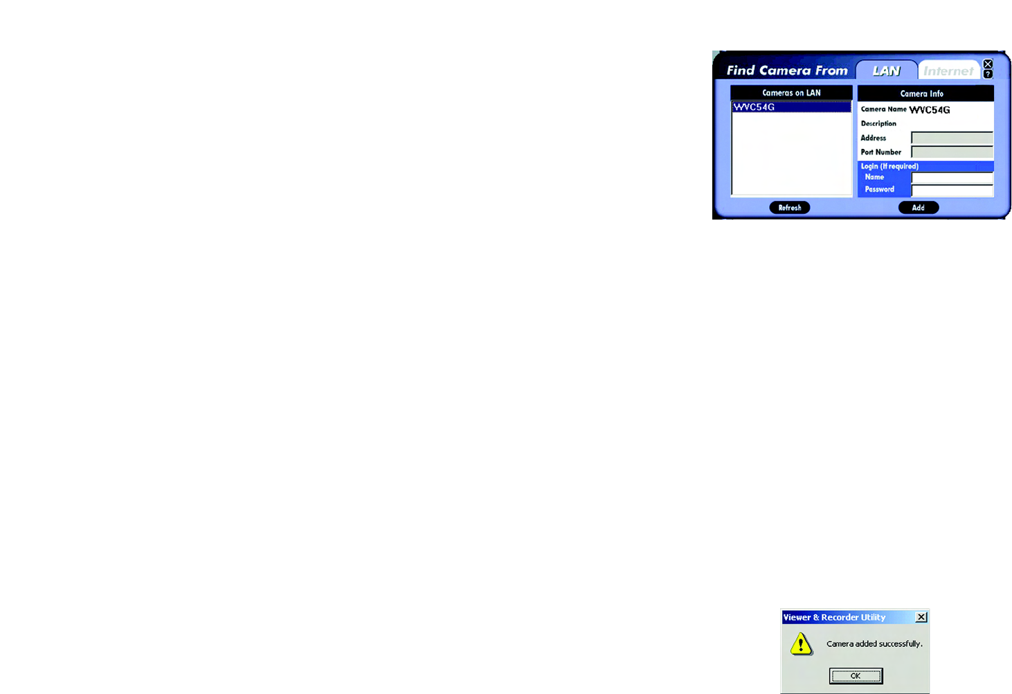
Find
To find a Camera on your local network or the Internet, click the Find button. There will be two tabs available, LAN
and Internet.
LAN
The LAN screen shows the Cameras found on your local area network, along with the status information for each
Camera.
Cameras on LAN
The Utility will search for Cameras on the local area network and display a list in the Cameras on LAN box. To run
a new search, click the Refresh button.
For the Camera whose name is currently selected in the Cameras on LAN box, the following information will be
displayed:
Camera Info
Camera Name. The name you gave to the Camera.
Description. The information about the Camera that you entered.
Address. The Camera’s IP address.
Port Number. The port number the Camera uses for communication.
Login. If you set up the Camera with a name and password, then you will need to enter them here in order to
access the Camera.
Name. Enter the login Name.
Password. Enter the login Password.
To add a Camera to the Utility’s list, select the Camera you wish to add by clicking its name in the Cameras on
LAN box. Then click the Add button. You will be notified when the Camera has been added. Click the OK button.
Figure 6-9: Find Camera from LAN Screen
Figure 6-10: Camera Added Successfully Screen
21
Chapter 6: Installing and Using the Wireless-G Internet Video Camera Viewer & Recorder Utility
Using the Viewer & Recorder Utility
Wireless-G Internet Video Camera
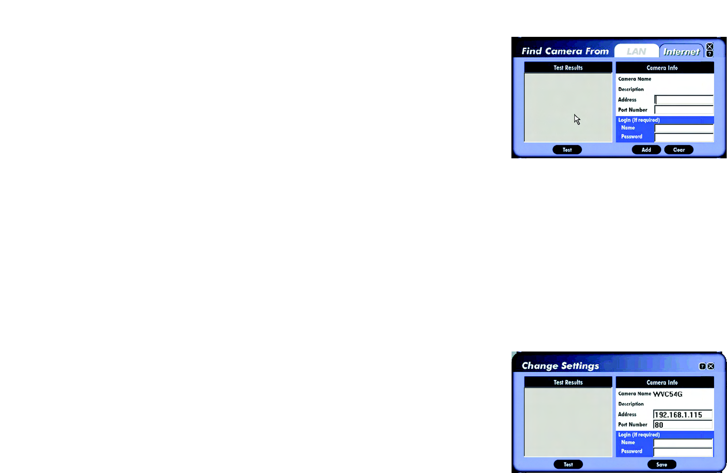
Internet
The Internet screen shows the Camera found on the Internet, along with the status information for it.
Test Results
First, go to the Camera Info section. Enter the Camera’s Address, Port Number, and login information (if required).
Then click the Test button to find the Camera. The following information will be displayed:
Camera Info
Camera Name. The name you gave to the Camera.
Description. The information about the Camera that you entered.
Address. The Camera’s IP address or SoloLink DDNS address.
Port Number. The port number the Camera uses for communication.
Login. If you set up the Camera with a name and password, then you will need to enter them here in order to
access the Camera.
Name. Enter the login Name.
Password. Enter the login Password.
To add the Camera to the Utility’s list, click the Add button. If you wish to clear a Camera, click the Clear button.
Change Settings
To modify a Camera’s settings, select its name in the Camera List box, and click the Change Settings button.
Test Results
First, make your changes to the Camera’s Address and Port Number fields as needed. If you set up the Camera
with a name and password, then you will need to enter them in the Name and Password fields in order to access
the Camera. Click the Save button to save your changes.
Click the Test button to make sure the Utility is able to find the Camera using the new information.
Figure 6-11: Find Camera from Internet Screen
Figure 6-12: Change Settings Screen
22
Chapter 6: Installing and Using the Wireless-G Internet Video Camera Viewer & Recorder Utility
Using the Viewer & Recorder Utility
Wireless-G Internet Video Camera
For the selected Camera, the following information will be displayed:
Camera Info
Camera Name. The name you gave to the Camera.
Description. The information about the Camera that you entered.
Address. The Camera’s IP address or your SoloLink DDNS address.
Port Number. The port number the Camera uses for communication.
Login. If you set up the Camera with a name and password, then enter them here to access the Camera.
Name. Enter the login Name.
Password. Enter the login Password.
If you want to save any changes, click the Save button.
Delete
To delete a Camera from the list, select the Camera by clicking its name in the Camera List box, and then click the
Delete button. When asked to confirm the deletion, click the Yes button.
Figure 6-13: Delete Camera Screen
Figure 6-14: Confirm Deletion of Camera Screen
23
Chapter 6: Installing and Using the Wireless-G Internet Video Camera Viewer & Recorder Utility
Using the Viewer & Recorder Utility
Wireless-G Internet Video Camera
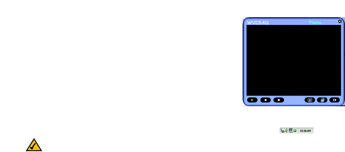
View
To view the video seen by a Camera, select the Camera by clicking its name in the Camera List box, and then click
the View button. You will see a screen similar to the one shown in Figure 6-15.
If you want to view video from a different Camera, return to the Utility’s main screen. Select this Camera from the
Camera List, and click View. Repeat this step for all the Cameras whose video you wish to view.
This screen provides six buttons:
• Play button (triangle) - Click this button to view video.
• Record button (circle) - Click this button to record the video. (You will see a rotating recording icon, which
alternates between blue and green, in the desktop’s system tray, as shown in Figure 6-16.)
• Stop button (square) - Click this button to stop recording or stop the video.
• Snapshot button (camera) - Click this button to take a snapshot of the current image.
• Audio button (speaker) - Audio is enabled by default. Click this button to disable it. When audio is disabled,
then a red dash will appear on this button. If you have disabled audio through the Web-based Utility, then
audio will not be available, and a red X will appear on this button.
• Magnification button (2X) - Click this button to view the video at twice its size. (This digital zoom feature is
only available for 320 x 480 and 160 x 128.)
Figure 6-16: Recording Icon Screen
Figure 6-15: View Video Screen
NOTE: If you are monitoring multiple Cameras and want to hear the audio from a single Camera,
then disable the audio from the other Cameras.

24
Chapter 6: Installing and Using the Wireless-G Internet Video Camera Viewer & Recorder Utility
Using the Viewer & Recorder Utility
Wireless-G Internet Video Camera
You may find it helpful to know how much memory is required to hold a video recording. The following tables list
estimated bit rates and file sizes for a recording at each available resolution and video. The first table shows
estimates for a typical video recording, while the second table shows estimates for an audio/video recording.
Estimated Hard-Drive Memory Space Required for Video Recording per Hour
Resolution Quality Level Bit Rate File Size
640 x 480 Very High 900kbps 270MB
640 x 480 High 700kbps 190MB
640 x 480 Normal 500kbps 130MB
640 x 480 Low 200kbps 117MB
640 x 480 Very Low 40kbps 105MB
320 x 240 Very High 900kbps 430MB
320 x 240 High 500kbps 330MB
320 x 240 Normal 300kbps 240MB
320 x 240 Low 120kbps 230MB
320 x 240 Very Low 40kbps 225MB
160 x 120 Very High 800kbps 380MB
160 x 120 High 400kbps 270MB
160 x 120 Normal 200kbps 230MB
160 x 120 Low 100kbps 220MB
160 x 120 Very Low 40kbps 210MB
NOTE: The maximum length of a recording file is one hour. If a recording is more than one hour long,
then multiple files will be saved.

25
Chapter 6: Installing and Using the Wireless-G Internet Video Camera Viewer & Recorder Utility
Using the Viewer & Recorder Utility
Wireless-G Internet Video Camera
Estimated Hard-Drive Memory Space Required for Audio/Video Recording per Hour
Resolution Quality Level Bit Rate File Size
640 x 480 Very High 900kbps 340MB
640 x 480 High 700kbps 210MB
640 x 480 Normal 500kbps 160MB
640 x 480 Low 200kbps 140MB
640 x 480 Very Low 40kbps 130MB
320 x 240 Very High 900kbps 480MB
320 x 240 High 500kbps 380MB
320 x 240 Normal 300kbps 270MB
320 x 240 Low 120kbps 240MB
320 x 240 Very Low 40kbps 230MB
160 x 120 Very High 800kbps 460MB
160 x 120 High 400kbps 300MB
160 x 120 Normal 200kbps 260MB
160 x 120 Low 100kbps 250MB
160 x 120 Very Low 40kbps 240MB
NOTE: The maximum length of a recording file is one hour. If a recording is more than one hour long,
then multiple files will be saved.
26
Chapter 6: Installing and Using the Wireless-G Internet Video Camera Viewer & Recorder Utility
Using the Viewer & Recorder Utility
Wireless-G Internet Video Camera
Scheduled Recordings in Progress
From the Scheduled Recordings in progress section, you can schedule recordings, alter the recording
preferences, and access recording files.
Recordings
The recordings listed here are scheduled ones that are currently in progress.
Camera Name. The name you gave to the Camera doing the recording.
Start Time. The time the recording began.
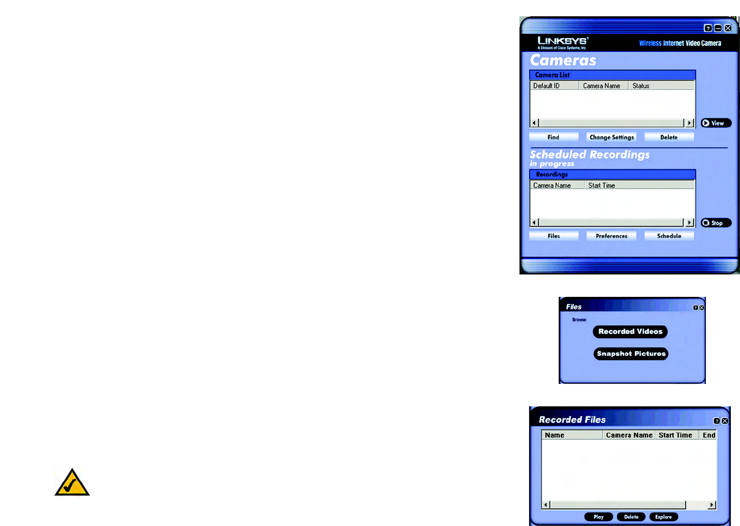
Files
To play, delete, or explore recording files, click the Files button.
The Files screen shows two choices. Click the Recorded Videos button if you want to browse for video
recordings. Click the Snapshot Pictures button if you want to browse for images.
Recorded Files
The Recorded Files screen shows the recordings available and their respective information.
Name. The name of the file. It begins with “Ir” if it was an instant recording. It begins with “Sr” if it was a
scheduled recording. The name ends with the date of the recording.
Camera Name. The name of the Camera.
Start Time. The time the recording began.
End Time. The time the recording ended.
Play
To play a recording file, select it by clicking its Name, and then click the Play button.
Figure 6-17: Scheduled Recordings in Progress Screen
Figure 6-18: Files Screen
Figure 6-19: Recorded Files Screen
Note: Use Windows Media Player 7 or higher to view your recordings.
27
Chapter 6: Installing and Using the Wireless-G Internet Video Camera Viewer & Recorder Utility
Using the Viewer & Recorder Utility
Wireless-G Internet Video Camera
Delete
To delete a recording file, select it by clicking its Name, and then click the Delete button.
Explore
If the recording file you want is not listed, click the Explore button to find the file.
To rename a recording file, click the Explore button. After you have found the file, you can rename it.
Snapshots
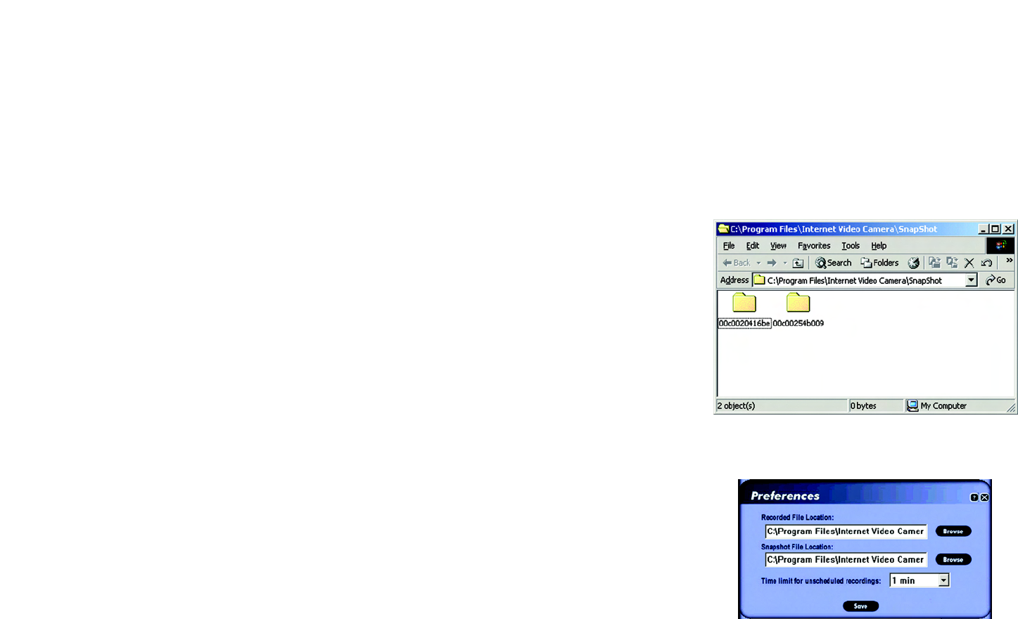
A window similar to the one shown in Figure 6-20 displays the available SnapShot folders. The name of each
folder is the MAC address of the Camera that took that folder’s snapshots. Double-click a folder to see a list of its
images.
Preferences
To designate the folder where recording files are saved, click the Preferences button. You can also customize the
time limit for unscheduled or instant recordings on the Preferences screen.
Recorded File Location
This shows the location where recording files are saved. You can enter a new location, or click the Browse button
to look for one.
Time limit for unscheduled recordings
You can customize the maximum amount of time an instant or unscheduled recording is allowed. Select the
appropriate amount of time from the drop-down menu. The default is one minute.
To save your changes, click the Save button.
Figure 6-20: Window Showing SnapShot Folders
Figure 6-21: Preferences Screen
28
Chapter 6: Installing and Using the Wireless-G Internet Video Camera Viewer & Recorder Utility
Using the Viewer & Recorder Utility
Wireless-G Internet Video Camera
Schedule
To view or modify the recording schedule, click the Schedule button.
The Recording Schedule screen shows the current recording schedule and each recording’s information.
Camera Name. The name of the Camera.
Date. The date of the recording.
Time. The start time of the recording.
Frequency. How often the recording will occur.
Add
To schedule a new recording, click the Add button.
Camera. Select the Camera you want for this recording.
Frequency. Select how often you want this recording to be made.
Start Date. Enter the date you want this recording to start.
Start Time. Enter the time you want this recording to start.
Duration. Enter the number of hours and minutes you want this recording to last.
When you are finished, click the Save button.
Modify
To modify a scheduled recording, select the recording by clicking its Camera Name, and then click the Modify
button.
Camera. This indicates the Camera that was selected for this recording.
Frequency. Alter how often you want this recording to be made.
Start Date. Alter the date you want this recording to start.
Start Time. Alter the time you want this recording to start.
Figure 6-22: Recording Schedule Screen
Figure 6-23: Add to Recording Schedule Screen
29
Chapter 6: Installing and Using the Wireless-G Internet Video Camera Viewer & Recorder Utility
Using the Viewer & Recorder Utility
Wireless-G Internet Video Camera
Duration. Alter the number of hours and minutes you want this recording to last.
When you are finished, click the Save button.
Delete
To delete a scheduled recording, select it by clicking its Camera Name, and then click the Delete button.
Stop
To terminate a scheduled recording that is currently in progress, select it by clicking its Camera Name, and click
the Stop button.
If you want to restart the scheduled recording, select the Camera you want by clicking its name in the Camera
List box, and click the View button. You will see a screen similar to the one shown in Figure 6-25. Click the button
with the circle to record the video. To stop recording, click the button with the square.
To set up the Linksys SoloLink Service, go to “Chapter 7: Setting up the Linksys SoloLink DDNS Service.”
If you want to use the Camera’s Web-based Utility, go to “Chapter 8: Using the Wireless-G Internet Video
Camera Web-based Utility.”
Figure 6-24: Stop Scheduled Recording Screen
Figure 6-25: View Video Screen
30
Chapter 7: Setting up the Linksys SoloLink™ DDNS Service
Overview
Wireless-G Internet Video Camera
Chapter 7: Setting up the Linksys SoloLink™ DDNS Service
Overview
This chapter will briefly discuss the Linksys SoloLink DDNS Service, explain how to set up your SoloLink account,
and describe how to register additional Cameras on your SoloLink account. You need only one SoloLink account.
Once you have set up your account, you can register additional Cameras, one at a time, through each Camera’s
Web-based Utility. This way each Camera can take advantage of the SoloLink DDNS Service.
Introduction
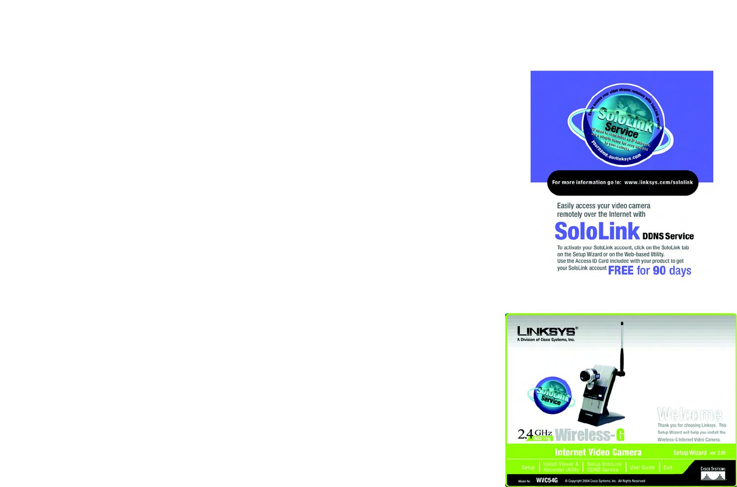
The SoloLink DDNS (Dynamic Domain Name System) Service lets you assign a fixed host and domain name to a
dynamic Internet IP address. The instructions in this chapter will guide you through the setup needed for use of
the SoloLink DDNS Service. For the most current information about the SoloLink DDNS Service, visit
www.linksys.com/sololink. For a free, 90-day trial period of your SoloLink account, use the Access ID Card
included with the Camera.
You may want to use the Linksys SoloLink DDNS Service if one of the following applies to you:
Dynamic IP Address - Your Internet service assigns you a dynamic IP address. Many Internet service providers
(ISPs) assign a new IP address to your connection from time to time (for security purposes), or whenever you
disconnect and reconnect. The SoloLink service keeps track of your network’s address, even when it changes, so
you can “find” the Camera.
Convenience - There are a couple of ways the SoloLink service can be convenient. If you have a static IP address,
you can use the SoloLink service to enter a “name” and port number for remote access of the Camera via the
Internet. There’s no need to type an entire IP address. For example, you can give a Camera a “name” such as
cam1.myhouse.ourlinksys.com.
Also, some DDNS services require your PC to continuously run software that lets them keep track of your IP
address. If your PC isn’t powered on when your IP address changes, you won’t be able to find the Camera on the
Internet. The SoloLink service keeps track of where the Camera is.
Setup Wizard for the SoloLink DDNS Service
1. On the Welcome or Congratulations screen of the Setup Wizard, click the Setup SoloLink DDNS Service
button. Figure 7-2: SoloLink Welcome Screen
Figure 7-1: SoloLink Service
31
Chapter 7: Setting up the Linksys SoloLink™ DDNS Service
Setup Wizard for the SoloLink DDNS Service
Wireless-G Internet Video Camera
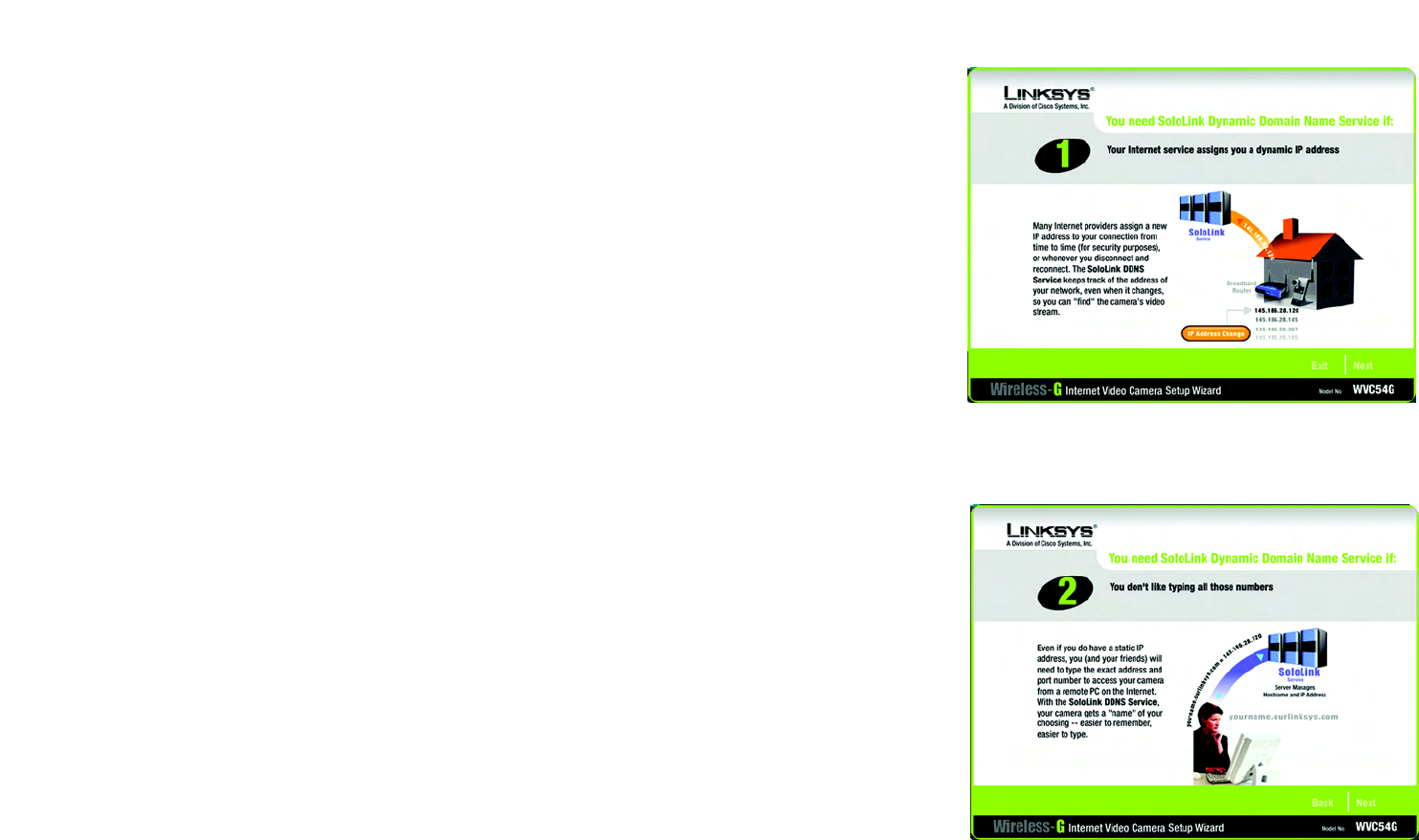
2. The screen shown in Figure 7-3 explains why you would want to use the SoloLink DDNS Service if your
network is using a dynamic IP address. Click the Next button.
3. The screen shown in Figure 7-4 explains why you would find the SoloLink DDNS Service convenient if you
would prefer to access the Camera using a name rather than a series of numbers (its IP address). Click the
Next button.
Figure 7-4: SoloLink for Convenience Screen
Figure 7-3: SoloLink for Dynamic IP Address Screen
32
Chapter 7: Setting up the Linksys SoloLink™ DDNS Service
Setup Wizard for the SoloLink DDNS Service
Wireless-G Internet Video Camera
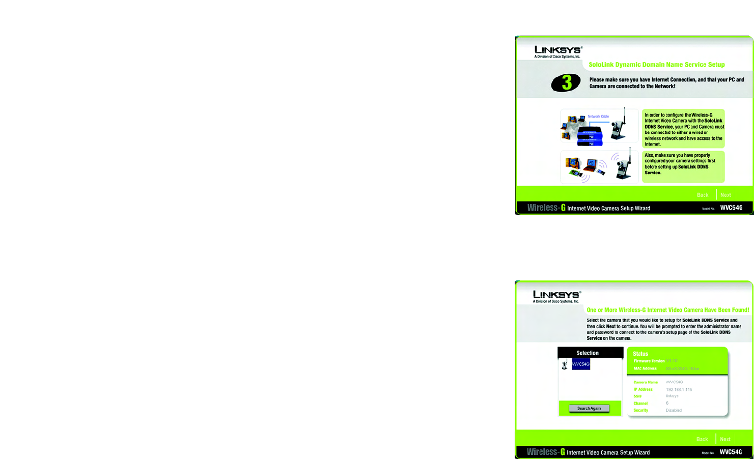
4. Make sure your network has an active Internet connection. Verify that your PC and Camera are connected to
the network and the Camera is configured properly. Click Next.
5. The screen shown in Figure 7-6 will display a list of Wireless-G Internet Video Cameras on your network and
their status information. In the Selection box, click the name of the Camera you are currently setting up. Click
Next.
Figure 7-5: Check Connections Screen
Figure 7-6: Cameras Found Screen
33
Chapter 7: Setting up the Linksys SoloLink™ DDNS Service
Setup Wizard for the SoloLink DDNS Service
Wireless-G Internet Video Camera
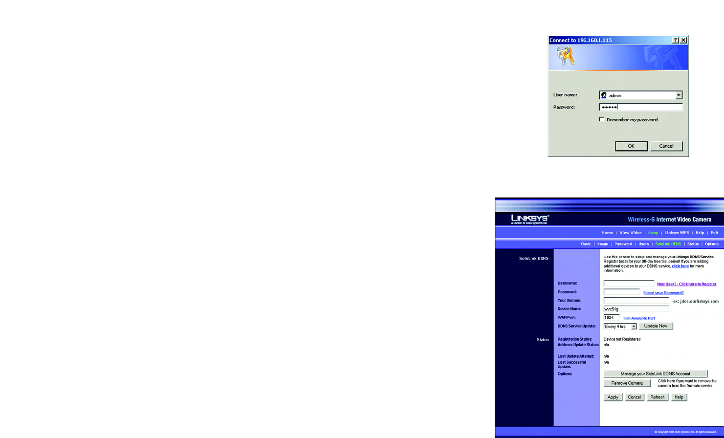
6. To ensure security, you will be asked to enter a user name and password before you can access the Camera.
If you have not changed the Camera’s user name and password, then enter admin in the User name and
Password fields (admin is the default). Then click OK.
7. Your web browser will automatically start up, and the SoloLink DDNS screen of the Camera’s Web-based
Utility will appear. Click New User ? - Click here to Register.
Figure 7-7: Login Screen
Figure 7-8: SoloLink DDNS Screen
34
Chapter 7: Setting up the Linksys SoloLink™ DDNS Service
Setup Wizard for the SoloLink DDNS Service
Wireless-G Internet Video Camera
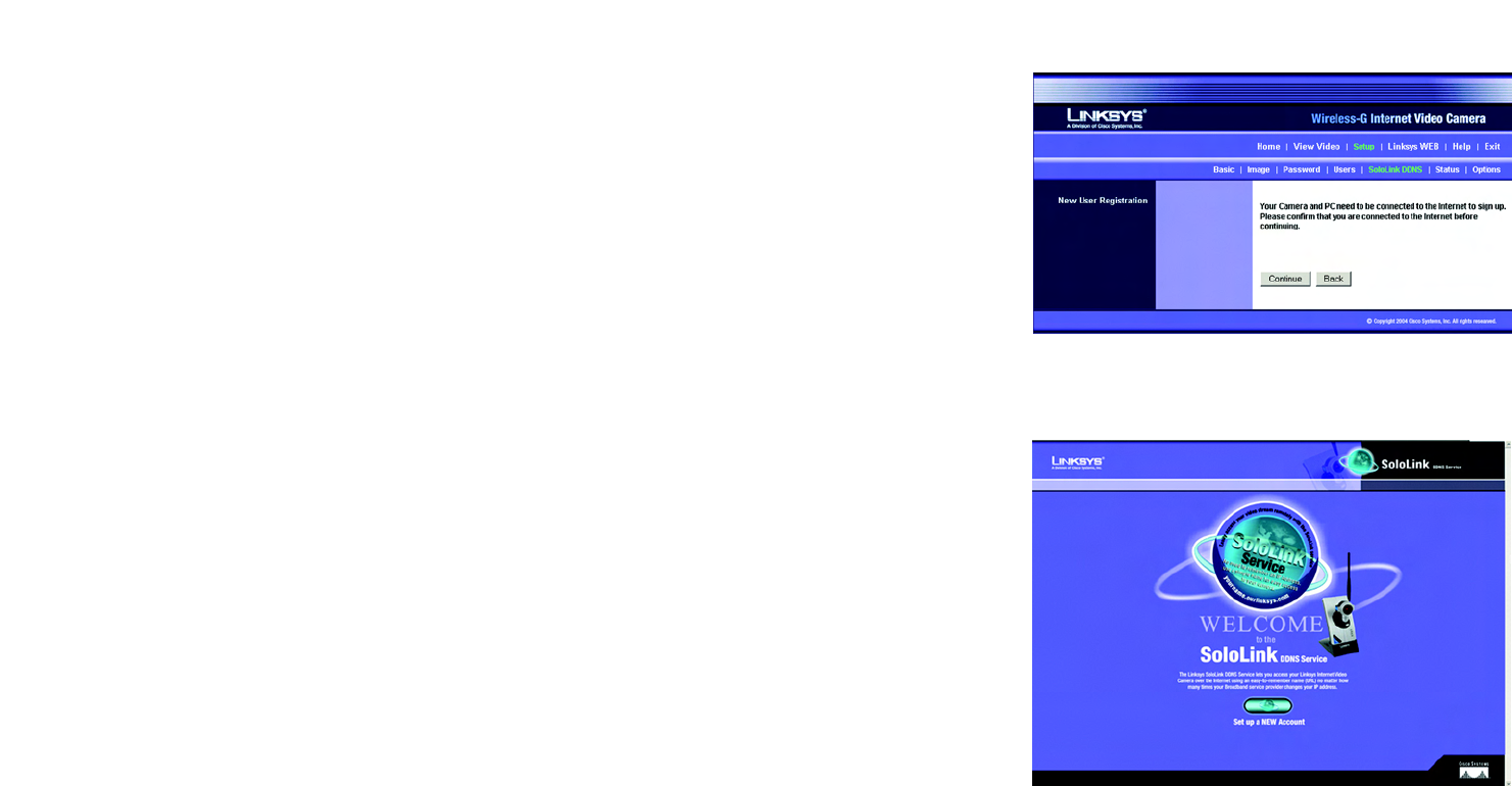
8. The screen shown in Figure 7-9 will ask you to make sure your network has an active Internet connection.
Click Continue.
9. On the Welcome to the SoloLink DDNS Service screen, click Set up a NEW Account.
Figure 7-9: Confirm Active Internet Connection Screen
Figure 7-10: Welcome to the SoloLink DDNS Service Screen
35
Chapter 7: Setting up the Linksys SoloLink™ DDNS Service
Setup Wizard for the SoloLink DDNS Service
Wireless-G Internet Video Camera
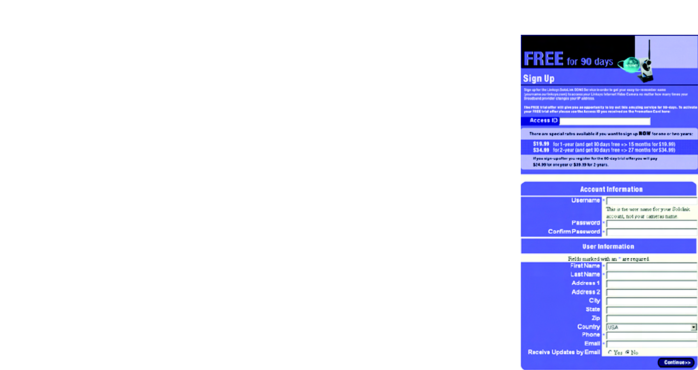
10. On the Sign Up screen, enter the Access ID for your free trial offer. It is provided on the Promotion Card
included with the Camera. (If you don’t have an Access ID, then leave the Access ID field blank.)
Then enter your account and user information. Enter a Username and Password for your account. Enter the
Password again in the Confirm Password field.
Complete the following required fields: First Name, Last Name, Phone, and Email. You can also enter your
postal address and choose to receive updates by e-mail. Then click Continue.
Figure 7-11: Sign Up Screen
36
Chapter 7: Setting up the Linksys SoloLink™ DDNS Service
Setup Wizard for the SoloLink DDNS Service
Wireless-G Internet Video Camera
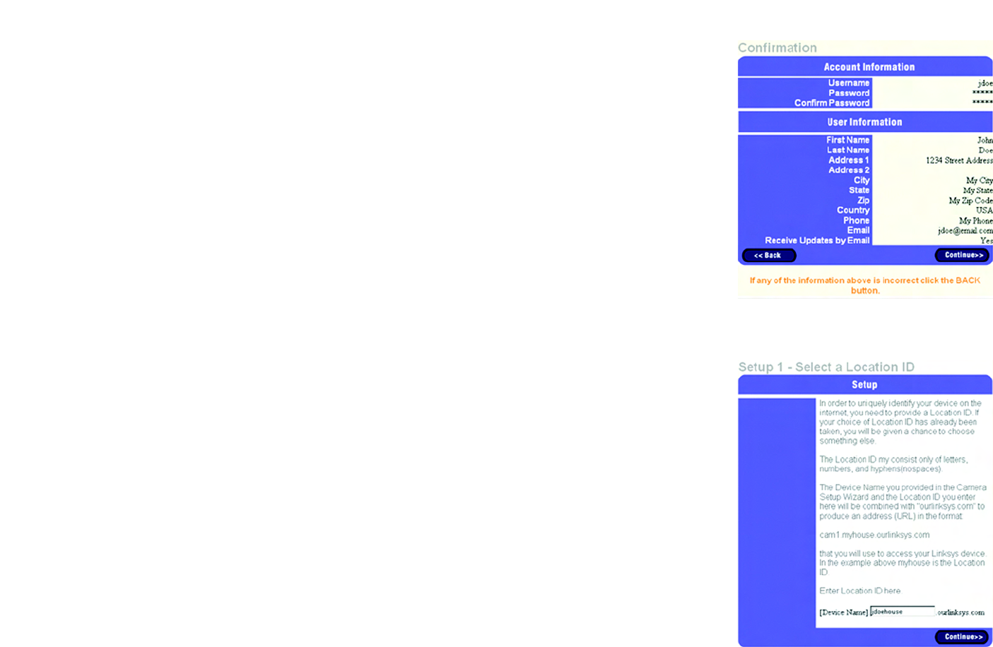
11. Review your information on the Confirmation screen. If the new settings are correct, click Continue.
12. On the Select a Location ID screen, enter a Location ID, which can be a name describing your network’s
location. It will be combined with the Camera’s Device Name and ourlinksys.com to create a convenient URL
you can use to access the Camera. Click Continue.
Figure 7-13: Select a Location ID Screen
Figure 7-12: Confirmation of New Settings Screen
37
Chapter 7: Setting up the Linksys SoloLink™ DDNS Service
Setup Wizard for the SoloLink DDNS Service
Wireless-G Internet Video Camera
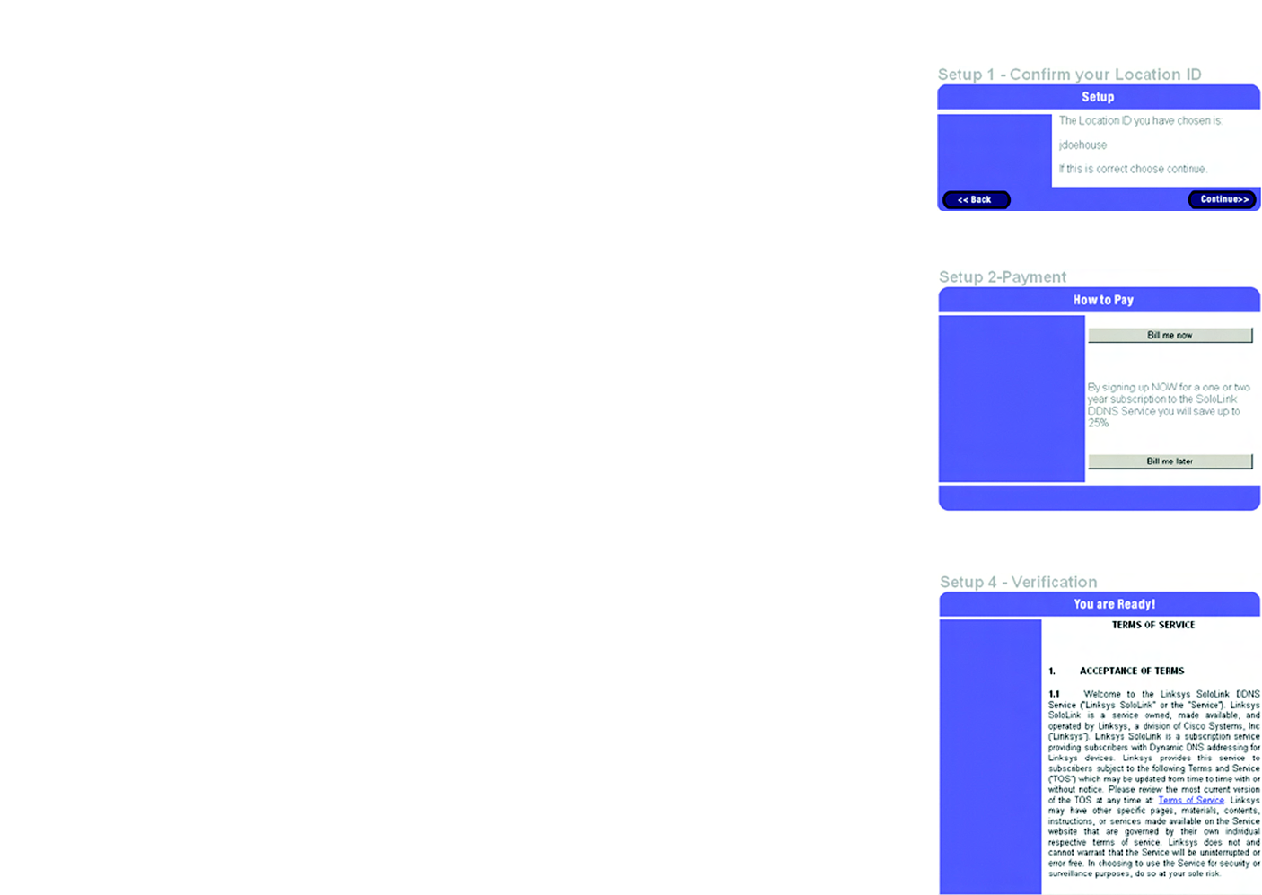
13. On the Confirm your Location ID screen, verify that the Location ID is correct. Then click Continue.
14. On the Payment screen, choose one of two payment plans, Bill me now or Bill me later. (If you did not enter
an Access ID, then you have one choice, Bill me now.)
If you click Bill me later, go to step 15.
If you click Bill me now, you will see a screen asking for billing information. Follow the on-screen instructions
and then go to step 15.
15. Read the Terms of Service agreement on the Verification screen. Click Create Account to accept the terms of
service.
Figure 7-15: Payment Screen
Figure 7-14: Confirm Your Location ID Screen
Figure 7-16: Verification Screen