LITE ON TECHNOLOGY IMP002 imp Module User Manual imp002 module 20130221
LITE-ON Technology Corp. imp Module imp002 module 20130221
UserManual.wiki
>
LITE ON TECHNOLOGY
>
IMP002 User Manual
Users manual
Navigation menu
Upload a User Manual
Namespaces
Wiki Guide
HTML
PDF
Info
Views
User Manual
Discussion / Help
Navigation
![PIN 6YesU6-TXPIN 7YesU2-RXSPI2-MOSIYesYesPIN 8YesU1-TXI2-SCLSPI1-MOSIYesYesPIN 9YesU1-RXI2-SDASPI1-MSOYesYesPIN AYesYesYesPIN BYesU4-RXYesYesPIN CYesYesPIN DYesU1-RXPIN EYesU6-RX7. Electrical characteristicsParameterConditionMinTypMaxUnit.Operating temperature-2055℃Operating voltage1.8[1]3.03.6VSleep currentWiFi is off, processor sleep, RTC on, nvram preserved6µAOperating current Normal operation, WiFi on7080400[2]mAOperating current Power-save mode enabled25400[2]mAPin driveMaximum current drive on I/O pins4mAVILI/O input low level voltageVSS-0.30.3VDDVVIHI/O input high level voltage0.7VDD3.6VLED current sink8mALoad capacitancePins 1 to 920pFLoad capacitancePins 10 to 145pFelectric imp, incelectric imp imp002 specification (confidential, not for distribution)"6](https://usermanual.wiki/LITE-ON-TECHNOLOGY/IMP002/User-Guide-1923324-Page-6.png)
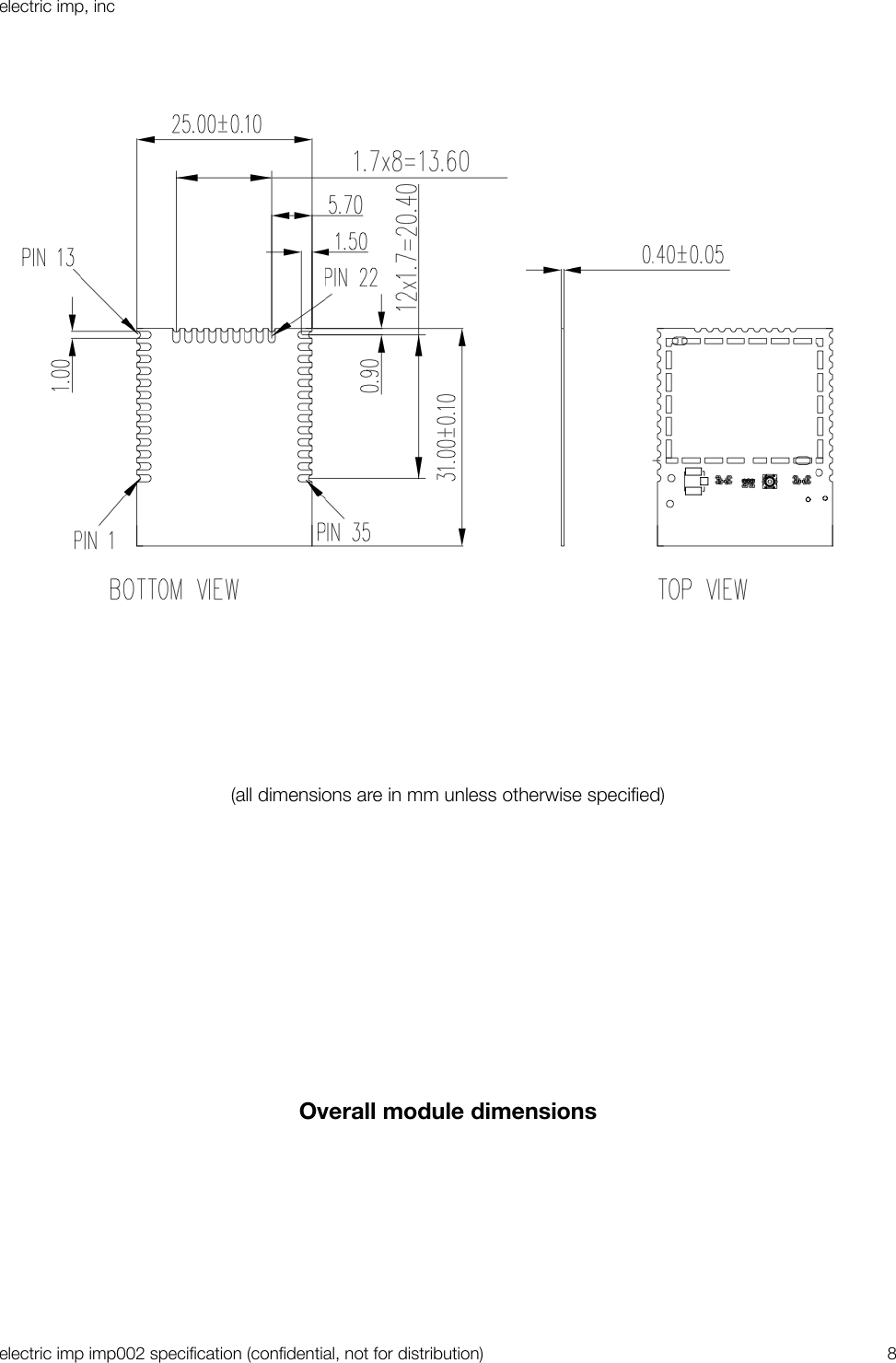
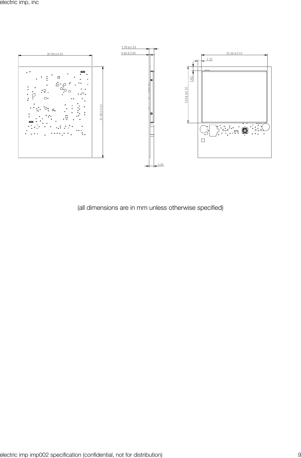
![I/O input leakage currentVSS ≦ VIN ≦ VDD4µA[1] WiFi requires 2.5v minimum for operation, but user code can run at 1.8v. The POWER_EN pin is driven to enable an external boost converter that will provide 2.5v+ during WiFi usage.[2] 400mA current is during worst-case TX events. These are a maximum of ~4.8ms long (802.11b 1Mbps)8. Package outlinePCB dimensionselectric imp, incelectric imp imp002 specification (confidential, not for distribution)"7](https://usermanual.wiki/LITE-ON-TECHNOLOGY/IMP002/User-Guide-1923324-Page-7.png)