LITE ON TECHNOLOGY IMP002 imp Module User Manual imp002 module 20130221
LITE-ON Technology Corp. imp Module imp002 module 20130221
Users manual


1. Product description
1.1 General description
The imp is a complete wireless network node in a module. It is available both in a memory card form-factor (imp001) and
in a solder-down module form-factor (imp002). It works in conjunction with the imp service to allow easy connection of
any device to the internet.
1.2 Features
•802.11 b/g/n WiFi
•20MHz 11n channels, 1 x 1
•+16.75dBm max output power (802.11b)
•-97dBm typical sensitivity (1Mbps)
•Integrated antenna with 2.5dBi max gain
•TX power
•802.11b 16.5dBm +/-1.5dBm
•802.11g 14.0dBm +/-1.5dBm
•802.11n 12.75dBm +/-1.5dBm
•32-bit Cortex M3 processor
•Robust embedded operating system with fail-safe firmware updates
•Virtual machine for vendor firmware
•LED drive for red/green status LEDs
•Phototransistor input for our patent-pending BlinkUp technology to provide optical configuration
•12 user selectable I/Os
•GPIO, PWM, Analog input & output
•SPI (2 channels), UART (4.5 channels), I2C (2 channels)
•Low power 6uA sleep mode
•FCC, CE, IC C-Tick certified
electric imp, inc
electric imp imp002 specification (confidential, not for distribution)"2

2. imp terminology
Term
Description
API
The Application Programming Interface through which imp scripts may access hardware and
cloud functions
BlinkUp
Our patent-pending optical programming process for commissioning an imp using a smart
device (phone or tablet)
Commissioning
Initializing an imp by associating it with a user account and WiFi credentials, usually via BlinkUp
electric imp
http://electricimp.com/aboutus/ (lower case by brand convention)
Planner
The imp cloud service which provides for the connection and configuration of imps and gateway
communication with other devices
Registration
The process by which an imp card or module becomes associated with host hardware
Server
The electric imp cloud service with which imps communicate
Firmware
Vendor provided code that runs within the imp’s virtual machine
Agent
Vendor provided code that runs within the imp service
electric imp, inc
electric imp imp002 specification (confidential, not for distribution)"3
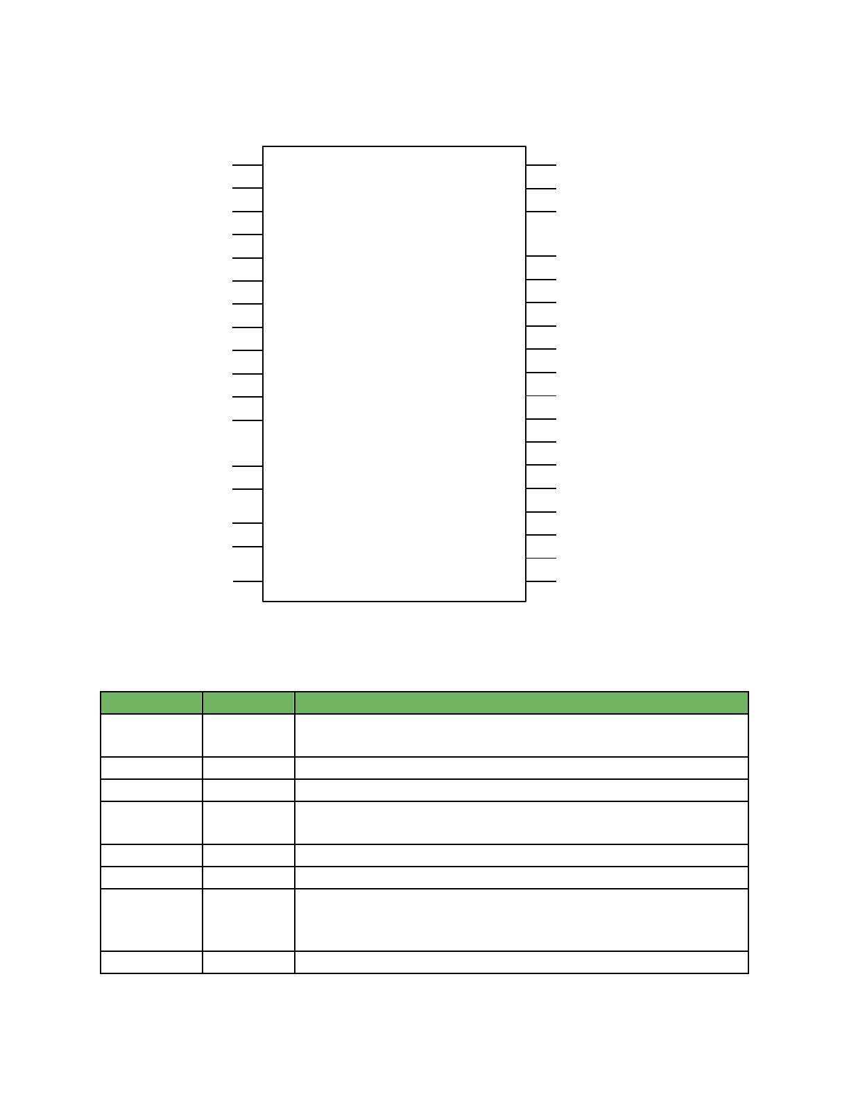
3. Pin assignments
4. Pin description
Pin number
Pin name
Description
1, 7, 13, 17, 23
to 32 & 35
GND1 to 15
Ground
18, 33
VDD
Power input
2
OPTO_BIAS
Phototransistor power; connects to collector of phototransistor
6
OPTO_IN
Phototransistor signal; connects to emitter of phototransistor, which is connected
to ground via a bias resistor (typically 100k)
3
LED_GREEN
Green LED open-drain output (connect to cathode of LED)
4
LED_RED
Red LED open-drain output (connect to cathode of LED)
5
POWER_EN
Active-high output for boost DCDC enable. Is driven high when the module
requires a 2.5-3.3v power supply, which is generally when WiFi is active. This pin
has an internal pulldown.
34
VREF
ADC reference voltage input. If unused, connect to VDD
electric imp, inc
electric imp imp002 specification (confidential, not for distribution)"4
8 to 12, 14 to 16
& 19 to 22
PIN1, 2, 5 to E
I/O, please refer to Pin mux table
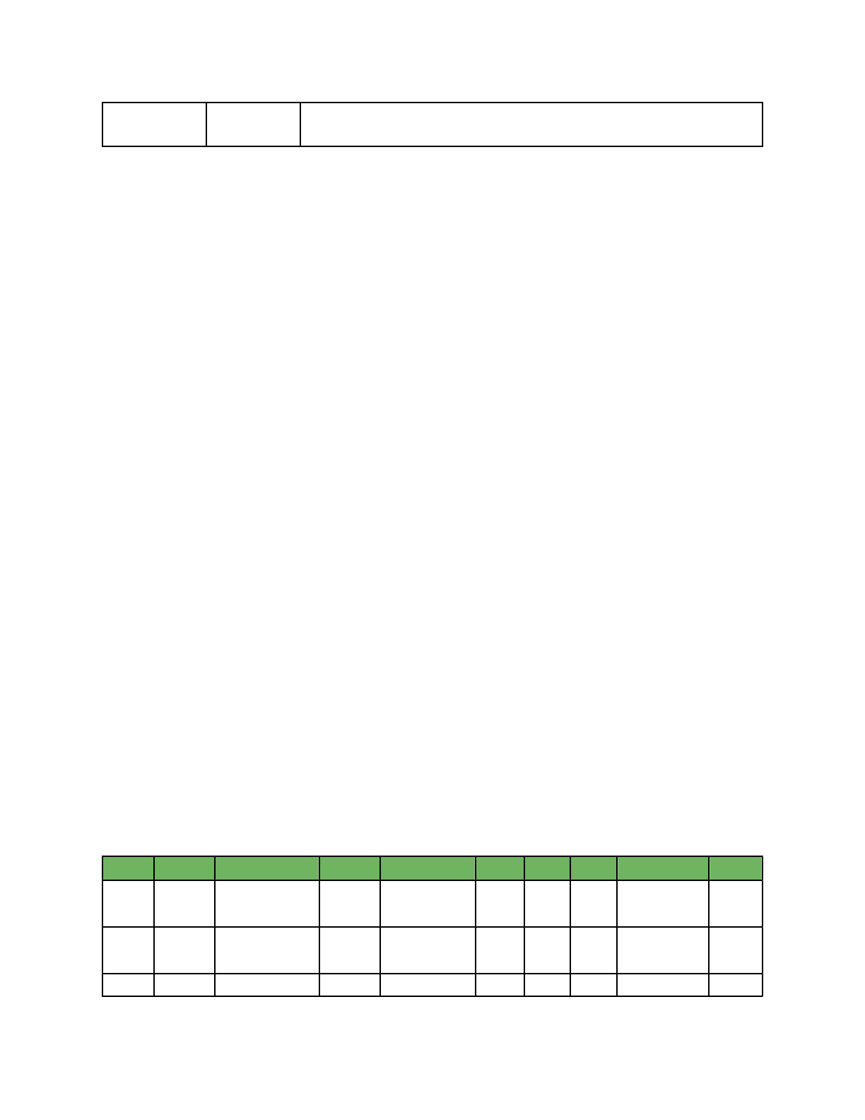
5. Pin mux
In addition to acting as a GPIO, each pin on the imp002 can be configured to one of several specialized functions. While
pins may only have one function at a time, they may be reconfigured during run-time to change function as needed. For
example, a pin may first be configured as a DAC and then reconfigured as an ADC. Additionally, not all the pins in a
hardware function need to be assigned to that function. For example, pins 8 and 9 could be used as UART and pins 1
and 2 could be used as I2C.
All I/O pins are initially tri-stated.
The imp002 can be woken from low power sleep mode with a rising edge on PIN1. If this signal is pulsed, the minimum
pulse width is 20ms.
Pin
GPIO
UART
I2C
SPI
DAC
ADC
PWM
Pulse Count
Wake
PIN 1
Yes
U1-CTS, U3-TX
I1-SCL
SPI1-SCLK
Yes
Yes
Yes
Yes
Yes
PIN 2
Yes
U1-RTS, U3-RX
I1-SDA
SPI2-MISO
Yes
Yes
PIN 5
Yes
U2-TX
SPI2-SCLK
Yes
Yes
Yes
electric imp, inc
electric imp imp002 specification (confidential, not for distribution)"5
PIN 6
Yes
U6-TX
PIN 7
Yes
U2-RX
SPI2-MOSI
Yes
Yes
PIN 8
Yes
U1-TX
I2-SCL
SPI1-MOSI
Yes
Yes
PIN 9
Yes
U1-RX
I2-SDA
SPI1-MSO
Yes
Yes
PIN A
Yes
Yes
Yes
PIN B
Yes
U4-RX
Yes
Yes
PIN C
Yes
Yes
PIN D
Yes
U1-RX
PIN E
Yes
U6-RX
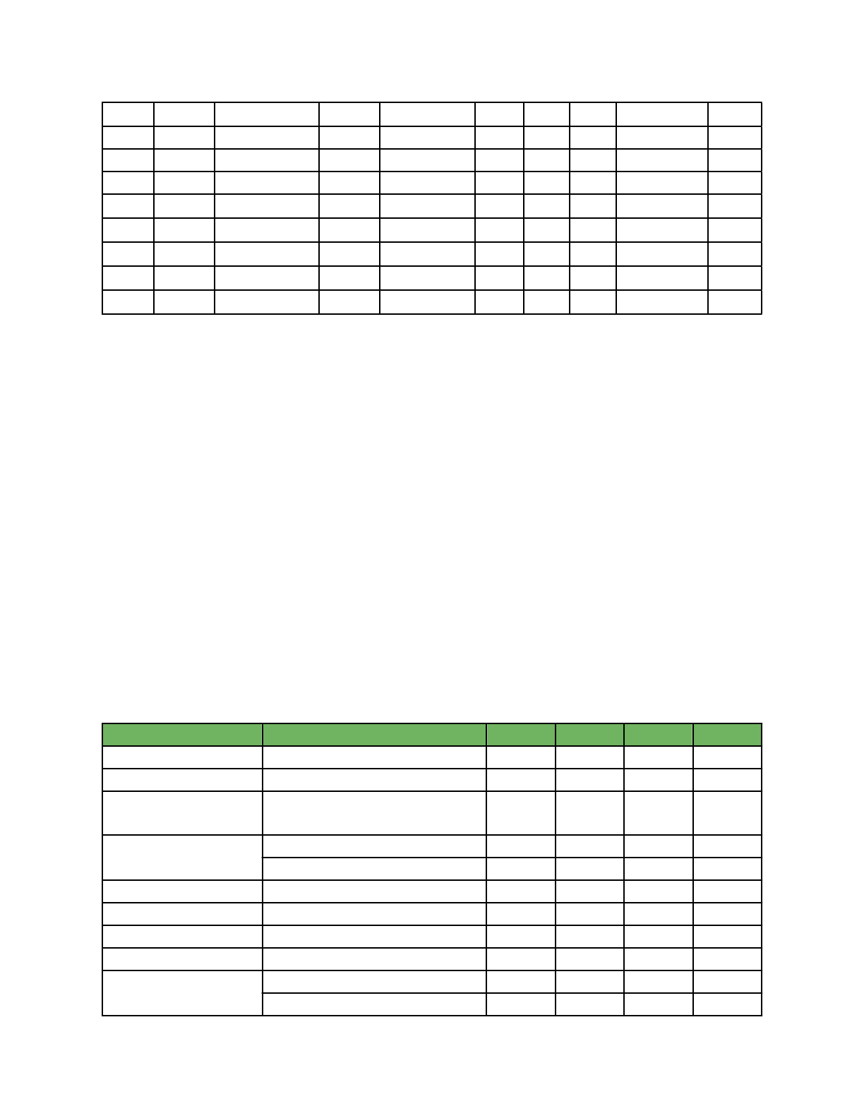
7. Electrical characteristics
Parameter
Condition
Min
Typ
Max
Unit.
Operating temperature
-20
55
℃
Operating voltage
1.8[1]
3.0
3.6
V
Sleep current
WiFi is off, processor sleep, RTC on,
nvram preserved
6
µA
Operating current
Normal operation, WiFi on
70
80
400[2]
mA
Operating current
Power-save mode enabled
2
5
400[2]
mA
Pin drive
Maximum current drive on I/O pins
4
mA
VIL
I/O input low level voltage
VSS-0.3
0.3VDD
V
VIH
I/O input high level voltage
0.7VDD
3.6
V
LED current sink
8
mA
Load capacitance
Pins 1 to 9
20
pF
Load capacitance
Pins 10 to 14
5
pF
electric imp, inc
electric imp imp002 specification (confidential, not for distribution)"6

I/O input leakage current
VSS ≦ VIN ≦ VDD
4
µA
[1] WiFi requires 2.5v minimum for operation, but user code can run at 1.8v. The POWER_EN pin is driven to enable an
external boost converter that will provide 2.5v+ during WiFi usage.
[2] 400mA current is during worst-case TX events. These are a maximum of ~4.8ms long (802.11b 1Mbps)
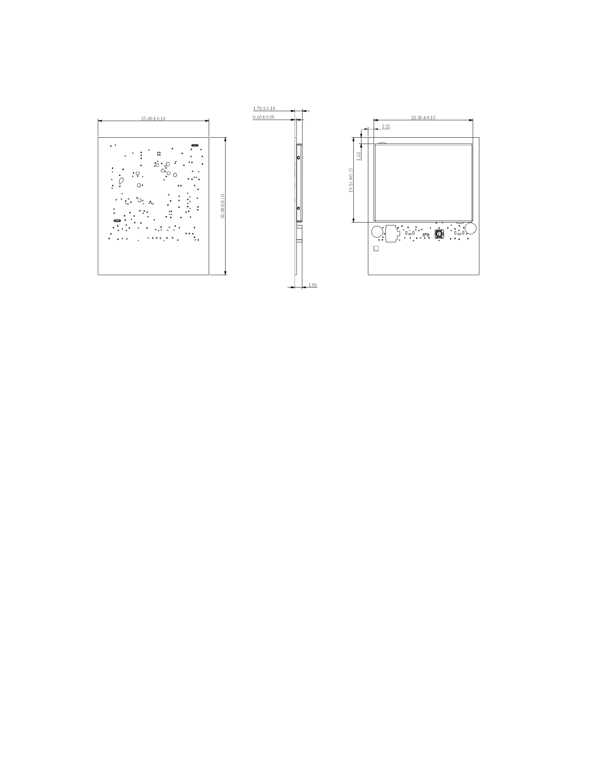
8. Package outline
PCB dimensions
electric imp, inc
electric imp imp002 specification (confidential, not for distribution)"7
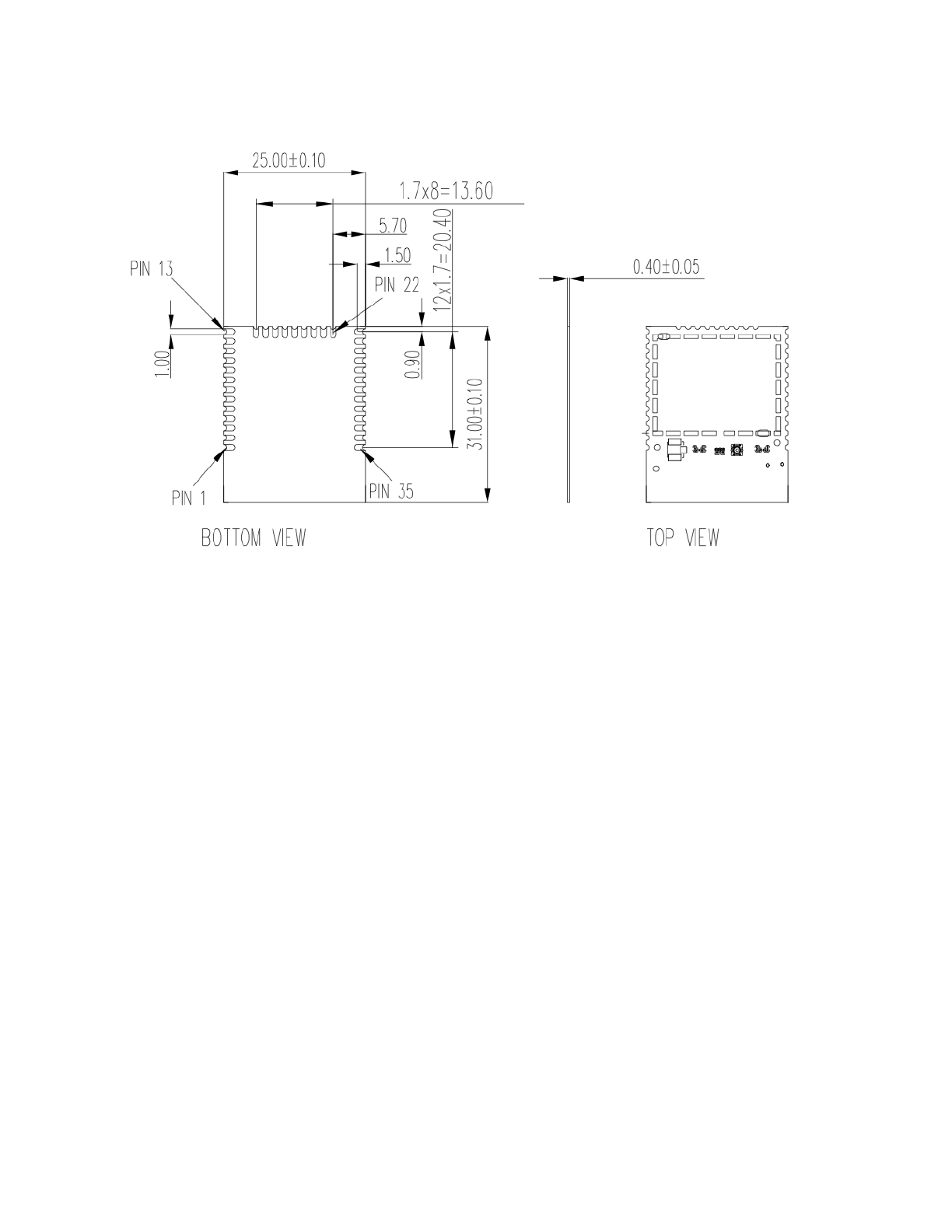
(all dimensions are in mm unless otherwise specified)
Overall module dimensions
electric imp, inc
electric imp imp002 specification (confidential, not for distribution)"8
(all dimensions are in mm unless otherwise specified)
electric imp, inc
electric imp imp002 specification (confidential, not for distribution)"9
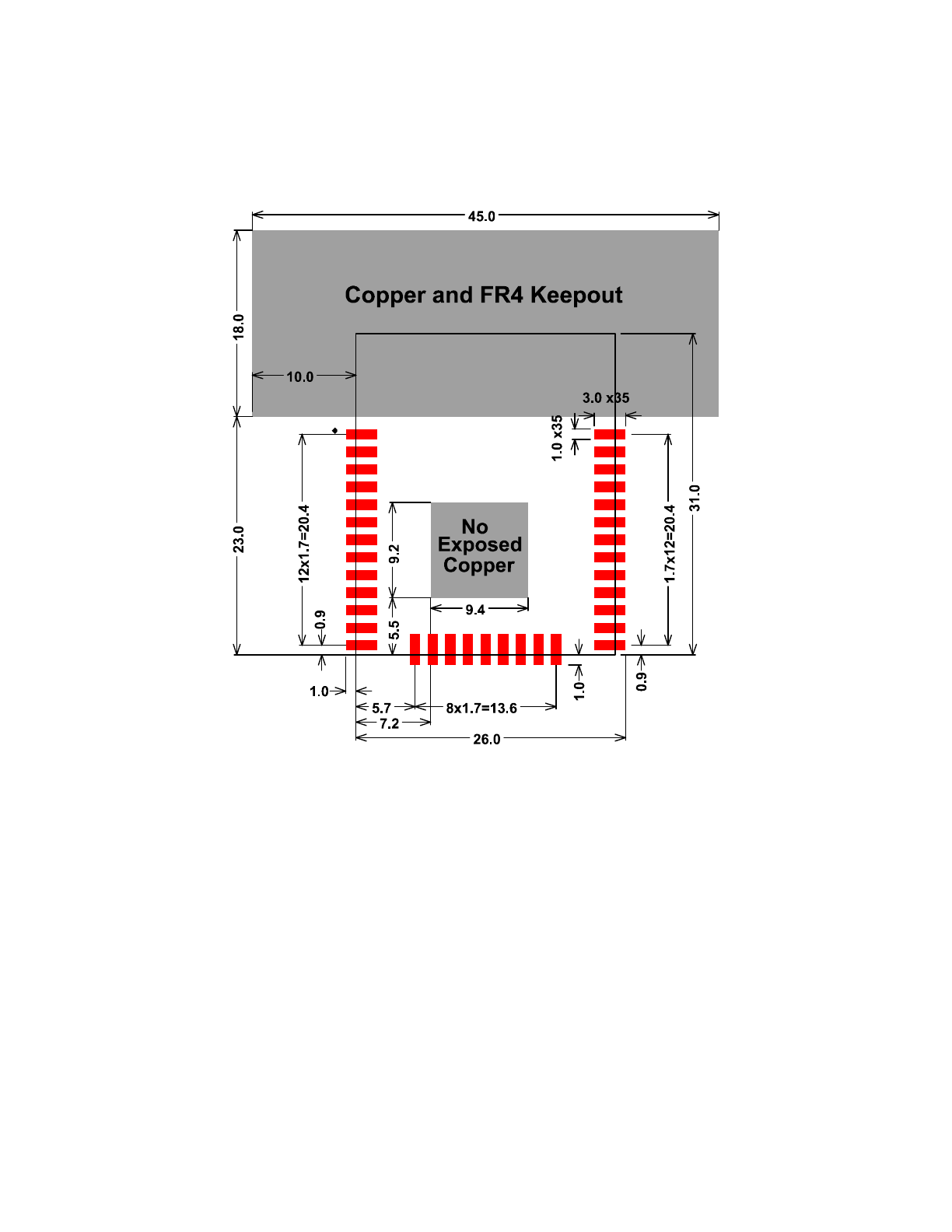
9. Recommended footprint
PAU2023
PAU2024
PAU2025
PAU2026
PAU2027
PAU2028
PAU2029
PAU2030
PAU2031
PAU2032
PAU2033
PAU2034
PAU2035
PAU201
PAU202
PAU203
PAU204
PAU205
PAU206
PAU207
PAU208
PAU209
PAU2010
PAU2011
PAU2012
PAU2013
PAU2014
PAU2015
PAU2016
PAU2017
PAU2018 PAU2019 PAU2020 PAU2021 PAU2022
COU2
(all dimensions are in mm unless otherwise specified)
electric imp, inc
electric imp imp002 specification (confidential, not for distribution)"10

FCC Caution: To assure continued compliance, (example - use only shielded interface cables when connecting to
computer or peripheral devices). Any changes or modifications not expressly approved by the party responsible for
compliance could void the user’s authority to operate this equipment.
This device complies with Part 15 of the FCC Rules. Operation is subject to the following two conditions: (1) This device
may not cause harmful interference, and (2) this device must accept any interference received, including interference that
may cause undesired operation.
Version
Change description
20121217
updated mechanical drawings to reflect the smaller coax connector
20130103
updated recommended footprint to have a cleaner look
20130122
changed PIN 10 to 14 to PIN A to E
20130218
added FCC caution statement
20130219
added TX power in paragraph 1.2
20310221
updated TX power values
electric imp, inc
electric imp imp002 specification (confidential, not for distribution)"11
Notice
This device complies with Part 15 of the FCC Rules. Operation is subject to the
following two conditions: (1) this device may not cause harmful interference and (2)
this device must accept any interference received, including interference that may
cause undesired operation.
For P15B equipment
This equipment has been tested and found to comply with the limits for a Class B
digital device, pursuant to part 15 of the FCC rules. These limits are designed to
provide reasonable protection against harmful interference in a residential installation.
This equipment generates, uses and can radiate radio frequency energy and, if not
installed and used in accordance with the instructions, may cause harmful interference
to radio communications. However, there is no guarantee that interference will not
occur in a particular installation. If this equipment does cause harmful interference to
radio or television reception, which can be determined by turning the equipment off
and on, the user is encouraged to try to correct the interference by one or more of the
following measures:
-Reorient or relocate the receiving antenna.
-Increase the separation between the equipment and receiver.
-Connect the equipment into an outlet on a circuit different from that to which the
receiver is connected.
-Consult the dealer or an experienced radio/TV technician for help.
Information To Be Supplied to the End User by the OEM or Integrator
The following regulatory and safety notices must be published in documentation supplied to
the end user of the product or system incorporating an adapter in compliance with local
regulations. Host system must be labeled with "Contains FCCID:PPQ-IMP002“, FCC ID
displayed on label.
This device is to be used only for mobile and fixed application. In order to re-use the imp Module
FCC approvals the antenna(s) used for this transmitter must be installed to provide a separation
distance of at least 20 cm from all persons and must not be co-located or operating in conjunction
with any other antenna or transmitter. If antenna is installed with a separation distance of less than
20 cm from all persons or is co-located or operating in conjunction with any other antenna or transmitter
then additional FCC testing may be required. End-Users must be provided with transmitter operation
conditions for satisfying RF exposure compliance.
OEM integrators must ensure that the end user has no manual instructions to remove or install
the imp module. The EUT has two antenna types (External & PIFA antenna) that as below.
Antennas used for this OEM module must not exceed 2dBi gain for External Antenna, and 2.86dBi is
for PIFA one for mobile and fixed operating configurations.
FCC Warning
Canada — Low-power license-exempt radio communication devices (RSS-210)
a. Common information Operation is subject to the following two conditions:
1. This device may not cause interference, and
2. This device must accept any interference, including interference that may cause
undesired operation of the device.
b. Operation in 2.4 GHz band To prevent radio interference to the licensed service,
this device is intended to be operated indoors and installation outdoors is subject to
licensing.
Canada - de faible puissance exempts de licence des appareils de communication
radio (CNR-210)
a. Informations communes
Son fonctionnement est soumis aux deux conditions suivantes:
1. Ce dispositif ne peut causer des interférences, et
2. Ce dispositif doit accepter toute interférence, y compris les interférences qui
peuvent causer un mauvais fonctionnement du dispositif.
b. Le fonctionnement en bande de 2,4 GHz Pour prévenir les interférences
radioélectriques aux services sous licence, cet appareil est destiné à être exploité à
l'intérieur et à l'extérieur d'installation est soumise à licence.
Information To Be Supplied to the End User by the OEM or Integrator
Modular information form OEM
Information to Be Supplied to the End User by the OEM or Integrator
The following regulatory and safety notices must be published in documentation supplied to
the end user of the product or system incorporating an adapter in compliance with local
regulations.
Host system must be labeled with "Contains IC: 4491A-IMP002 “
This device is to be used only for mobile and fixed application. In order to re-use the imp Module
IC approvals the antenna(s) used for this transmitter must be installed to provide a separation
distance of at least 20 cm from all persons and must not be co-located or operating in conjunction
with any other antenna or transmitter. If antenna is installed with a separation distance of less than
20 cm from all persons or is co-located or operating in conjunction with any other antenna or transmitter
then additional IC testing may be required. End-Users must be provided with transmitter operation
conditions for satisfying RF exposure compliance.
OEM integrators must ensure that the end user has no manual instructions to remove or install
the imp module. The EUT has two antenna types (External & PIFA antenna) that as below.
Antennas used for this OEM module must not exceed 2dBi gain for External Antenna, and 2.86dBi is
for PIFA one. Both are for mobile and fixed operating configurations.
IC Warning