LITE ON TECHNOLOGY O90 Access Point/Sensor User Manual
LITE-ON Technology Corp. Access Point/Sensor
User Manual
O-90 AirTight Access Point / Sensor
Quick Start Guide
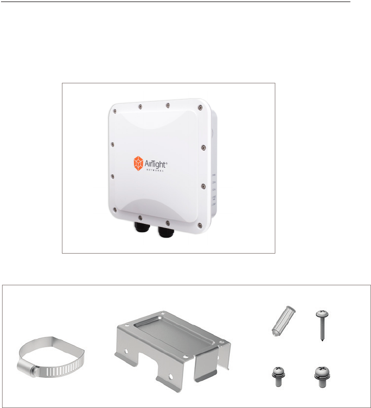
Package Contents
You should have received the following components in your O-90 package.
Mounting Accessories
O-90
x 1
x 2
x 4 x 4
x 1
x 4
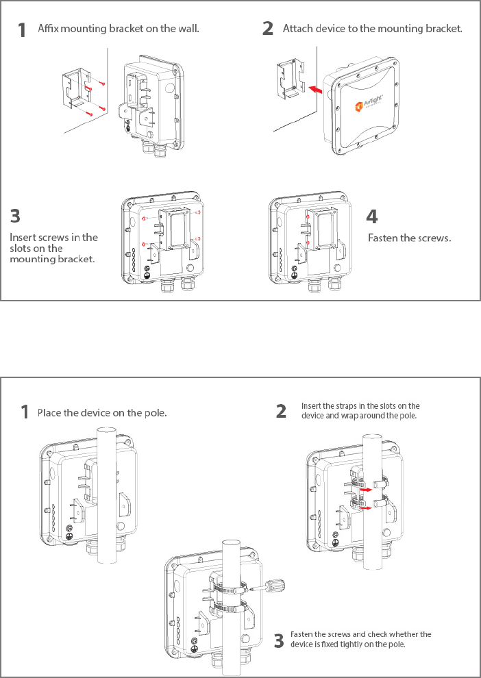
Wall Mount: AirTight logo facing away from the wall
Pole Mount: AirTight logo facing away from the wall
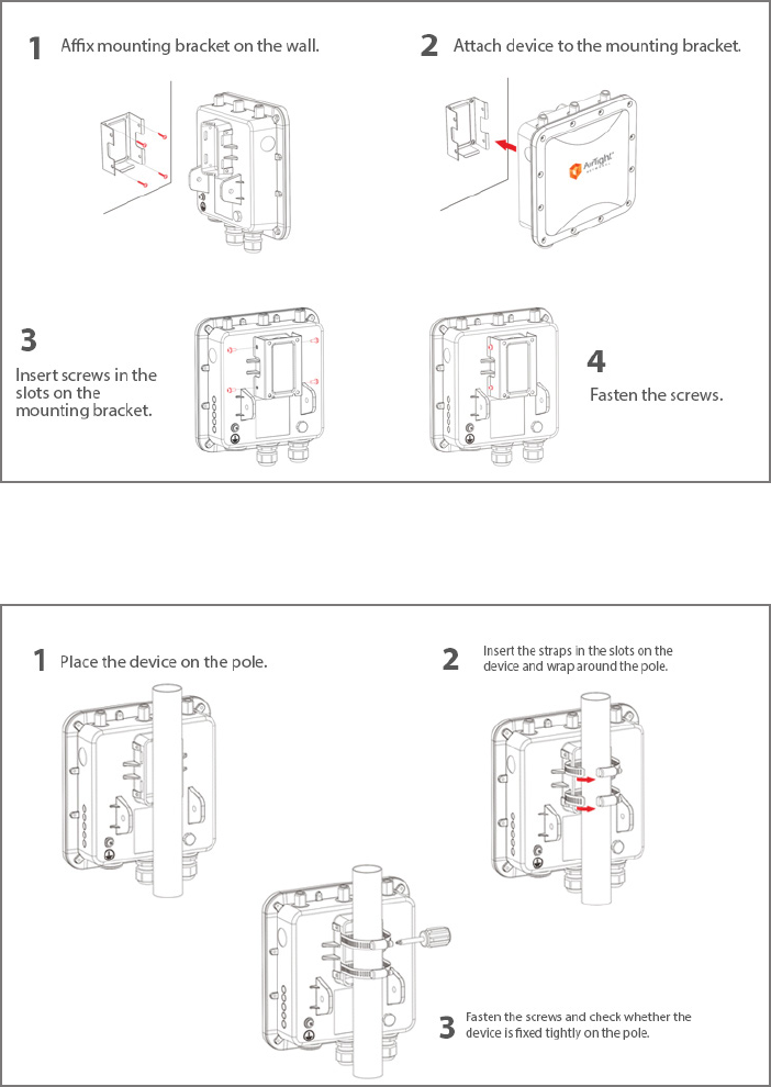
Mounting the O-90
Getting the O-90 Online
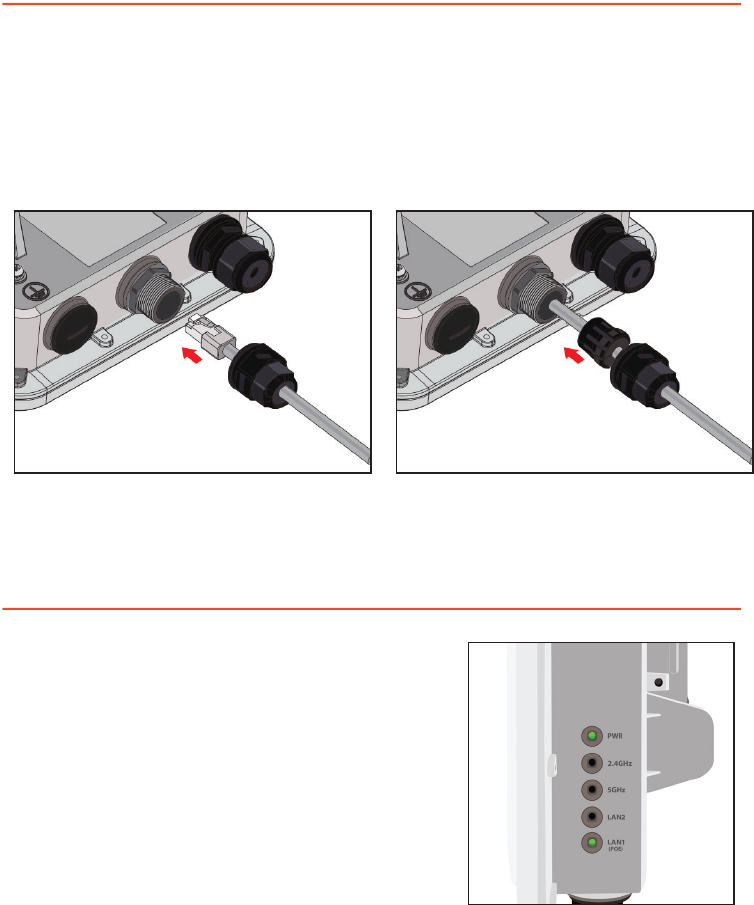
Step 1: Power up
Plug one end of the Ethernet cable into the PoE switch or injector and plug the other
end into the LAN1 (PoE) on the O-90. Make sure the PoE source you are using is
turned ON.
Step 2: Connect to the network
As you are using PoE, the O-90 should already be connected to your network.
Step 3: Check the LED status
Wait for a few minutes till the
Power (PWR) LED and LAN1 (PoE) LED
turn solid GREEN, which indicates that
the O-90 is online and operational.

Troubleshooting
After the O-90 is powered ON and connected to Ethernet, if the status
of Power (PWR) LED is not Solid Green, it indicates that the AP is not able to function
normally. The following guidelines may help you to quickly diagnose and x the problem.
LED Status
What does it mean?
Power (PWR) 2.4G/
5G
LAN2 LAN1 (PoE)
O O O O Not powered on or it is in the process of starting
up
Solid Orange Any On/ O Solid Green No active Ethernet link1
Solid Orange Any On/ O Fast Blink
Green
Did not receive a valid IP address via DHCP2
Solid Orange Any On/ O Slow Blink
Green
Unable to connect to the AirTight Cloud Services
or AirTight Server3
1. Make sure that the Ethernet cable is correctly plugged into the LAN1 (POE) port on
the O-90 and the other end of the cable is plugged into an Ethernet jack or a port on
a switch that is turned ON.
2. If the O-90 did not receive a valid IP address from the DHCP server, make sure that a
DHCP server is ON and available on the VLAN/subnet to which the AP is connected. If
the AP still fails to get a valid IP address, you can reboot it once to see if that resolves
the problem.
3. If you are using AirTight Cloud Services, make sure that Internet connectivity is
available from the VLAN/subnet to which the AP is connected. Check if the required
ports for AP and Server communication – UDP 3851 and default HTTP (TCP port 80)
– are open on the Firewall. If you are using a Proxy, Web accelerator or URL content
ltering, make sure the settings allow communication between the AP and AirTight
Cloud Services.
After following these guidelines, if you are still unable to resolve the problem, contact the
local AirTight Sales Engineer or 24/7 AirTight Technical Support.
Tel: +1 (650) 641 0027 Email: support@airtightnetworks.com
AirTight Networks, Inc. 339 N. Bernardo Avenue #200, Mountain View, CA 94043
T +1.877.424.7844 T 650.961.1111 F 650.961.1169 www.airtightnetworks.com info@airtightnetworks.com
AirTight O-90 Quick Setup Guide [Doc ID: ATN-QS-0315-001-00-EN]
© 2014 AirTight Networks, Inc. All rights reserved. AirTight Networks and the AirTight Networks logo are trademarks, and AirTight is a registered
trademark of AirTight Networks, Inc. All other trademarks mentioned herein are properties of their respective owners. Specications are subject to
change without notice.
Comprehensive Cloud-Managed Wi-Fi
O-90-E AirTight Access Point / Sensor
Quick Start Guide
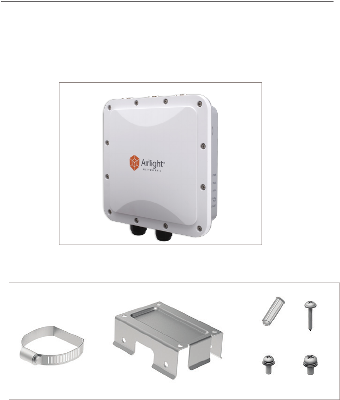
Package Contents
You should have received the following components in your O-90-E package.
Mounting Accessories
O-90-E
x 1
x 2
x 4 x 4
x 1
x 4
Wall Mount: AirTight logo facing away from the wall
Pole Mount: AirTight logo facing away from the wall
Mounting the O-90-E

Getting the O-90-E Online
Step 1: Power up
Plug one end of the Ethernet cable into the PoE switch or injector and plug the other
end into the LAN1 (PoE) on the O-90-E. Make sure the PoE source you are using is
turned ON.
Step 2: Connect to the network
As you are using PoE, the O-90-E should already be connected to your network.
Step 3: Check the LED status
Wait for a few minutes till the
Power (PWR) LED and LAN1 (PoE) LED
turn solid GREEN, which indicates that
the O-90-E is online and operational.

Troubleshooting
After the O-90-E is powered ON and connected to Ethernet, if the status
of Power (PWR) LED is not Solid Green, it indicates that the AP is not able to function
normally. The following guidelines may help you to quickly diagnose and x the problem.
LED Status
What does it mean?
Power (PWR) 2.4G/
5G
LAN2 LAN1 (PoE)
O O O O Not powered on or it is in the process of starting
up
Solid Orange Any On/ O Solid Green No active Ethernet link1
Solid Orange Any On/ O Fast Blink
Green
Did not receive a valid IP address via DHCP2
Solid Orange Any On/ O Slow Blink
Green
Unable to connect to the AirTight Cloud Services
or AirTight Server3
1. Make sure that the Ethernet cable is correctly plugged into the LAN1 (POE) port on
the O-90-E and the other end of the cable is plugged into an Ethernet jack or a port
on a switch that is turned ON.
2. If the O-90-E did not receive a valid IP address from the DHCP server, make sure that a
DHCP server is ON and available on the VLAN/subnet to which the AP is connected. If
the AP still fails to get a valid IP address, you can reboot it once to see if that resolves
the problem.
3. If you are using AirTight Cloud Services, make sure that Internet connectivity is
available from the VLAN/subnet to which the AP is connected. Check if the required
ports for AP and Server communication – UDP 3851 and default HTTP (TCP port 80)
– are open on the Firewall. If you are using a Proxy, Web accelerator or URL content
ltering, make sure the settings allow communication between the AP and AirTight
Cloud Services.
After following these guidelines, if you are still unable to resolve the problem, contact the
local AirTight Sales Engineer or 24/7 AirTight Technical Support.
Tel: +1 (650) 641 0027 Email: support@airtightnetworks.com
AirTight Networks, Inc. 339 N. Bernardo Avenue #200, Mountain View, CA 94043
T +1.877.424.7844 T 650.961.1111 F 650.961.1169 www.airtightnetworks.com info@airtightnetworks.com
AirTight O-90 Quick Setup Guide [Doc ID: ATN-QS-0315-002-00-EN]
© 2014 AirTight Networks, Inc. All rights reserved. AirTight Networks and the AirTight Networks logo are trademarks, and AirTight is a registered
trademark of AirTight Networks, Inc. All other trademarks mentioned herein are properties of their respective owners. Specications are subject to
change without notice.
Comprehensive Cloud-Managed Wi-Fi

Federal Communication Commission Interference Statement
FCC Warning
This equipment has been tested and found to comply with the limits for a Class A digital device, pursu-
ant to part 15 of the FCC Rules. These limits are designed to provide reasonable protection against
harmful interference when the equipment is operated in a commercial environment. This equipment
generates, uses, and can radiate radio frequency energy and, if not installed and used in accordance
with the instruction manual, may cause harmful interference to radio communications. Operation of
this equipment in a residential
area is likely to cause harmful interference in which case the user will be required to correct the inter-
ference at his own expense.
CAUTION:
Any changes or modications not expressly approved by the grantee of this device could void the
user’s authority to operate the equipment.
This device complies with Part 15 of the FCC Rules. Operation is subject to the following two condi-
tions: (1) this device may not cause harmful interference, and (2) this device must accept any interfer-
ence received, including interference that may cause undesired operation.
RF exposure warning
This equipment must be installed and operated in accordance with provided instructions and the
antenna(s) used for this transmitter must be installed to provide a separation distance of at least 20
cm from all persons and must not be co-located or operating in conjunction with any other antenna
or transmitter. End-users and installers must be provide with antenna installation instructions and
transmitter operating conditions for satisfying RF exposure compliance.
This radio transmitter FCCID: PPQ-O90 has been approved by FCC to operate with the antenna types
listed below with the maximum permissible gain and required antenna impedance for each antenna
type indicated. Antenna types not included in this list, having a gain greater than the maximum gain
indicated for that type, are strictly prohibited for use with this device.
Antenna List
No. Manufacturer Part No. Antenna Type Peak Gain
1 Walsin RFDPA25205AMLB801 dipole 5.01dBi for 2.4 GHz ;
6.07 dBi for 5 GHz

Canada, Industry Canada (IC) Notices
This device complies with Canada licence-exempt RSS standard(s).
Operation is subject to the following two conditions: (1) this device may not cause interference, and (2)
this device must accept any interference, including interference that may cause undesired operation of
the device.
Canada, avis d’Industry Canada (IC)
Cet appareil est conforme avec Industrie Canada exemptes de licence RSS standard(s).
Son fonctionnement est soumis aux deux conditions suivantes : (1) cet appareil ne doit pas causer
d’interférence et (2) cet appareil doit accepter toute interférence, notamment les interférences qui peu-
vent aecter son fonctionnement.
Radio Frequency (RF) Exposure Information
The radiated output power of the Wireless Device is below the Industry Canada (IC) radio frequency
exposure limits. The Wireless Device should be used in such a manner such that the potential for human
contact during normal operation is minimized.
This device has also been evaluated and shown compliant with the IC RF Exposure limits under mobile
exposure conditions. (antennas are greater than 20cm from a person’s body).
Informations concernant l’exposition aux fréquences radio (RF)
La puissance de sortie émise par l’appareil de sans l est inférieure à la limite d’exposition aux fréquences
radio d’Industry Canada (IC). Utilisez l’appareil de sans l de façon à minimiser les contacts humains lors
du fonctionnement normal.
Ce périphérique a également été évalué et démontré conforme aux limites d’exposition aux RF d’IC dans
des conditions d’exposition à des appareils mobiles (antennes sont supérieures à 20 cm à partir du corps
d’une personne).
This radio transmitter IC: 4491A-O90 has been approved by Industry Canada to operate with
the antenna types listed below with the maximum permissible gain and required antenna impedance
for each antenna type indicated. Antenna types not included in this list, having a gain greater than the
maximum gain indicated for that type, are strictly prohibited for use with this device.
Cet émetteur radio IC: 4491A-O90 a été approuvé par Industrie Canada pour fonctionner avec les types
d’antennes énumérés ci‐dessous avec le gain maximal admissible et impédance d’antenne requise
pour chaque type d’antenne indiqué. Types d’antennes n’est pas inclus dans cette liste, ayant un gain
supérieur au gain maximal indiqué pour ce type, sont strictement interdits pour une utilisation avec cet
appareil.
Antenna List
No. Manufacturer Part No. Antenna Type Peak Gain
1 Walsin RFDPA25205AMLB801 dipole 5.01dBi for 2.4 GHz ;
6.07 dBi for 5 GHz
Industry Canada Statement