LITE ON TECHNOLOGY SS335 1X1 802.11b/g/n-BT4.0 Combo PCIe MoB Module User Manual LiteOn Technology Corp
LITE-ON Technology Corp. 1X1 802.11b/g/n-BT4.0 Combo PCIe MoB Module LiteOn Technology Corp
UserManual.wiki
>
LITE ON TECHNOLOGY
>
SS335 User Manual
>
UserMan
Contents
1.
UserMan
2.
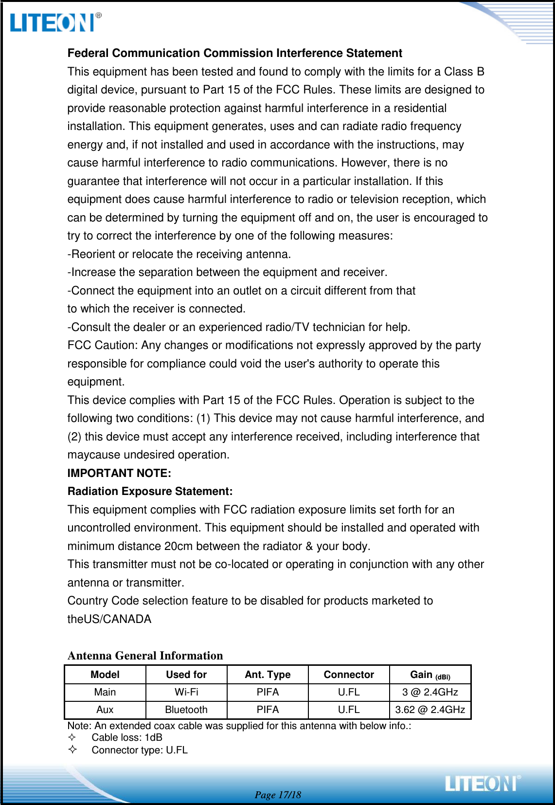
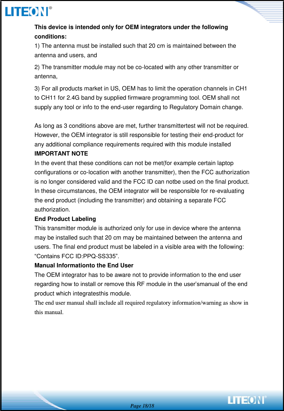
User manual
UserMan
Navigation menu
Upload a User Manual
Namespaces
Wiki Guide
HTML
PDF
Info
Views
User Manual
Discussion / Help
Navigation