LITE ON TECHNOLOGY SS335 1X1 802.11b/g/n-BT4.0 Combo PCIe MoB Module User Manual LiteOn Technology Corp
LITE-ON Technology Corp. 1X1 802.11b/g/n-BT4.0 Combo PCIe MoB Module LiteOn Technology Corp
Contents
- 1. UserMan
- 2. User manual
UserMan
Page 1/18
PRODUCT SPECIFICATION
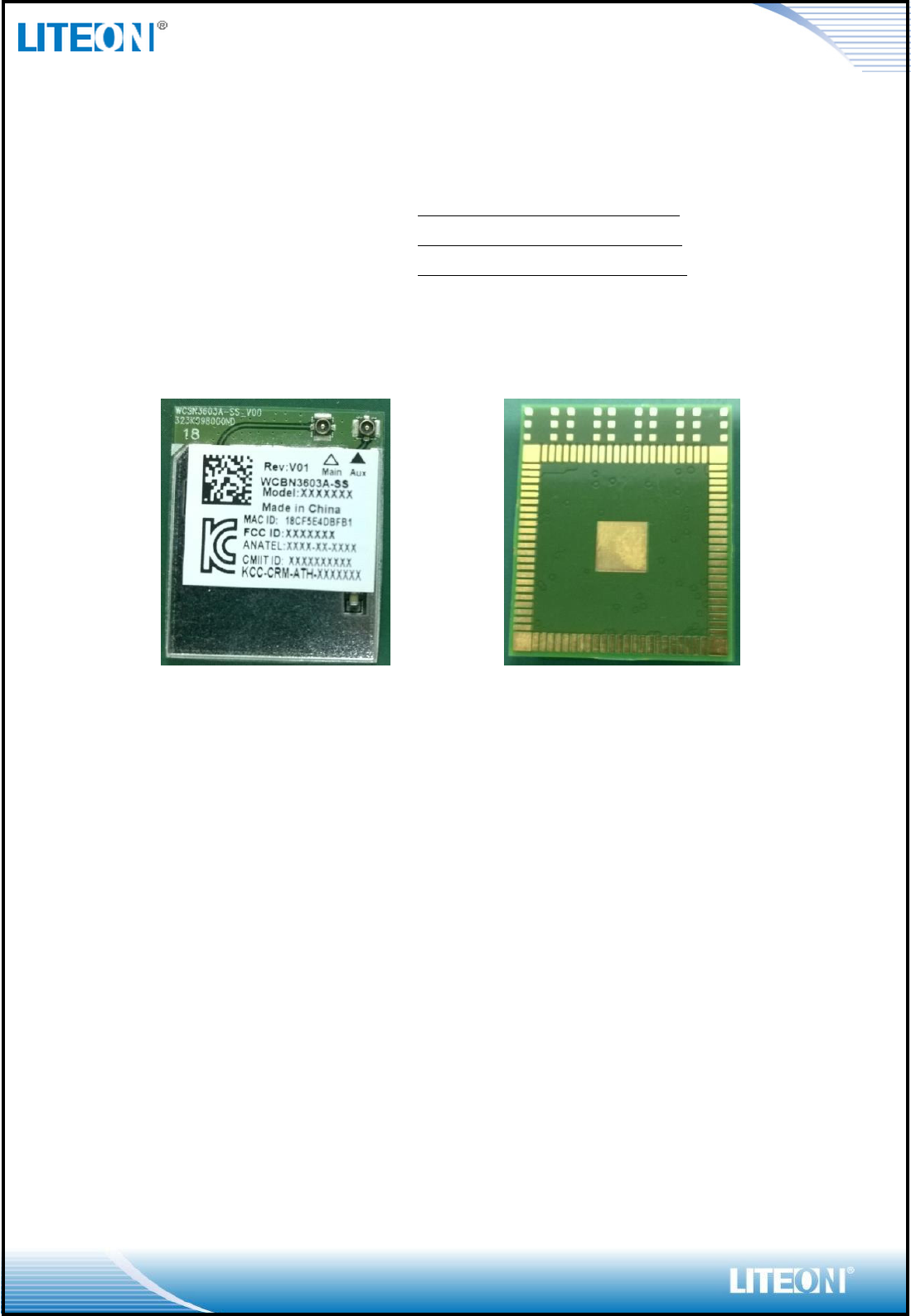
MODEL NAME: WCBN3603A-SS
MODULE PN: AAZ100075G0
SEC CODE:
Version 1.0
TOP
Bottom
* This document contains confidential proprietary information and is property of LTC. The contents of
this document should not be disclosed to unauthorized persons without the written consent of LTC.
Page 2/18
CONTENT
1. CHANGE HISTORY ..................................................................................................................... 3
2. LOCATION INFORMATION FOR MANUFACTURING FACTORY .................................. 3
3. GENERAL DESCRIPTION .......................................................................................................... 4
BT FEATURE: ......................................................................................................................................... 4
WIFI FEATURE: ...................................................................................................................................... 4
COMMON FEATURE: ............................................................................................................................... 4
4. CTQ (CRITICAL TO QUALITY), MAIN CONTROL ITEMS ................................................ 5
5. ELECTRICAL CHARACTERISTICS ........................................................................................ 5
6. TEST SETUP .................................................................................................................................. 6
7. INTERNAL BLOCK DIAGRAM ................................................................................................. 7
8. BASIC THEORY ............................................................................................................................ 7
9. PIN DEFINITON ............................................................................................................................ 8
10. APPLICATION NOTE ................................................................................................................ 9
11. SPECIFICATION OF MEASUREMENT JIG ........................................................................ 10
12. REFLOW PROFILE .................................................................................................................. 11
13. INITIAL TEST REPORT .......................................................................................................... 11
14. RELIABILITY TEST REPORT ............................................................................................... 12
15. MECHANICAL CHARACTERISTICS ................................................................................... 12
16. STRUCTURE AND MATERIAL ............................................................................................. 12
17. PACKAGING REEL & TAPE .................................................................................................. 12
18. MARKING .................................................................................................................................. 15
19. CONTROL CHART ................................................................................................................... 15
20. LEAD FREE ................................................................................................................................ 16
21. ROHS QUALIFICATION REPORT ........................................................................................ 16
22. SAMPLE HISTORY .................................................................................................................. 16
23. BOM LIST ................................................................................................................................... 16
Page 3/18
1. Change History
Revision
Date
Author
Change List
Version 1.0
2014/06/18
Kaysa Lee
Preliminary
2. Location information for Manufacturing Factory
1st Case
2nd Case
3rd Case
Fab
x
Assembly
Lite-On CZ
Final Test
Lite-On CZ
Page 4/18
3. General Description
BT Feature:
Bluetooth V4.0 LE, V3.0 HS, Bluetooth V2.1+EDR system, backwards compatible with BT version
of 1.1, 1.2 and 2.0
Support Class II (TX power maximum to +4dBm)
BT transmission speed including 1M, 2M and 3Mbps EDR operations
Support for Simple Pairing (SP) and Enhanced Inquiry Response (EIR) function
Support for SCATTERNET and PICONET
HCI USB interface to work with Windows upper layer stack
WiFi Feature:
Operate at ISM frequency Band(2.4GHz)
IEEE Standards Support, 802.11b, 802.11g and 802.11n
WiFi using mini PCIe interface
Enterprise level security supporting: WPA, WPA2
Support 1 transmission and 1 receiving, transmission rate can up to 150Mbps (Physical Rate) in
downstream and upstream
Full feature software utility for easy configuration and management
Common Feature:
Form Factor: M.2 2226
Support OS: Windows Win7/Win8
Support for BT & WLAN Co-existence
RoHS Compliance
Low Halogen Compliance
WiFi:
Reg Domain
Most of World SKU
Channel 1-11 with active scan
Channel 12~13 with passive scan
0x006A
Vendor ID
0x168C
Device ID
0x0036
Subsystem ID
0x4129
Subsystem Vendor ID
0x144D
BT:
Vendor ID
0x0CF3
Product ID
0x3004
Page 5/18
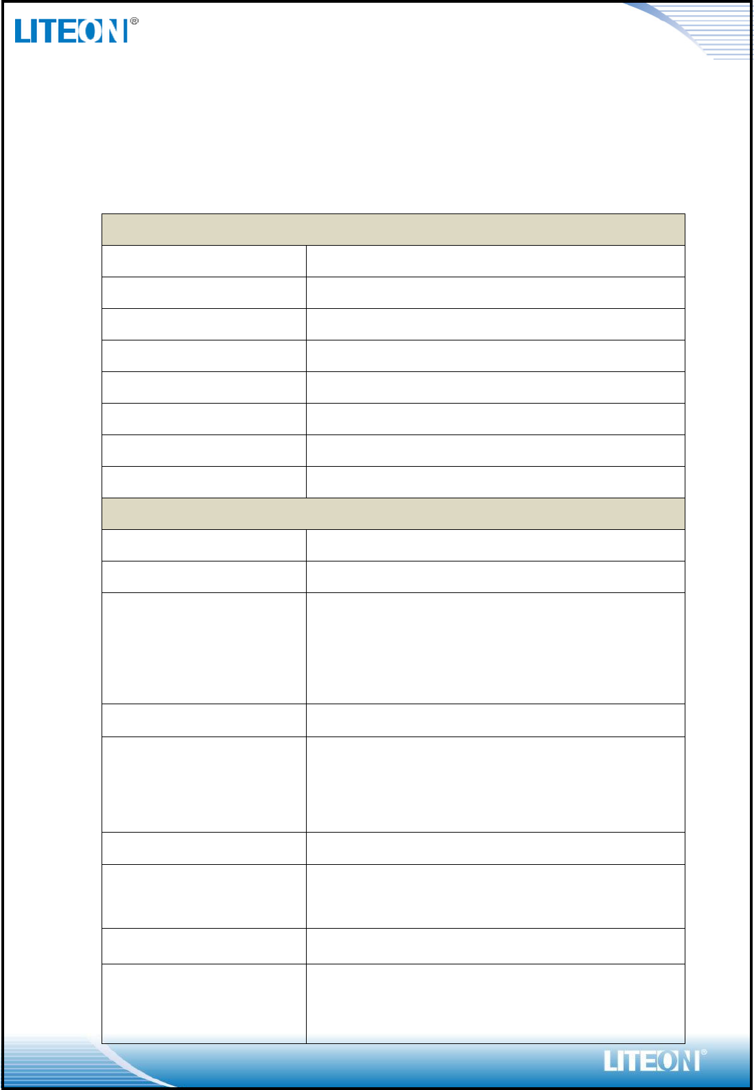
4. CTQ (Critical To Quality), Main Control Items
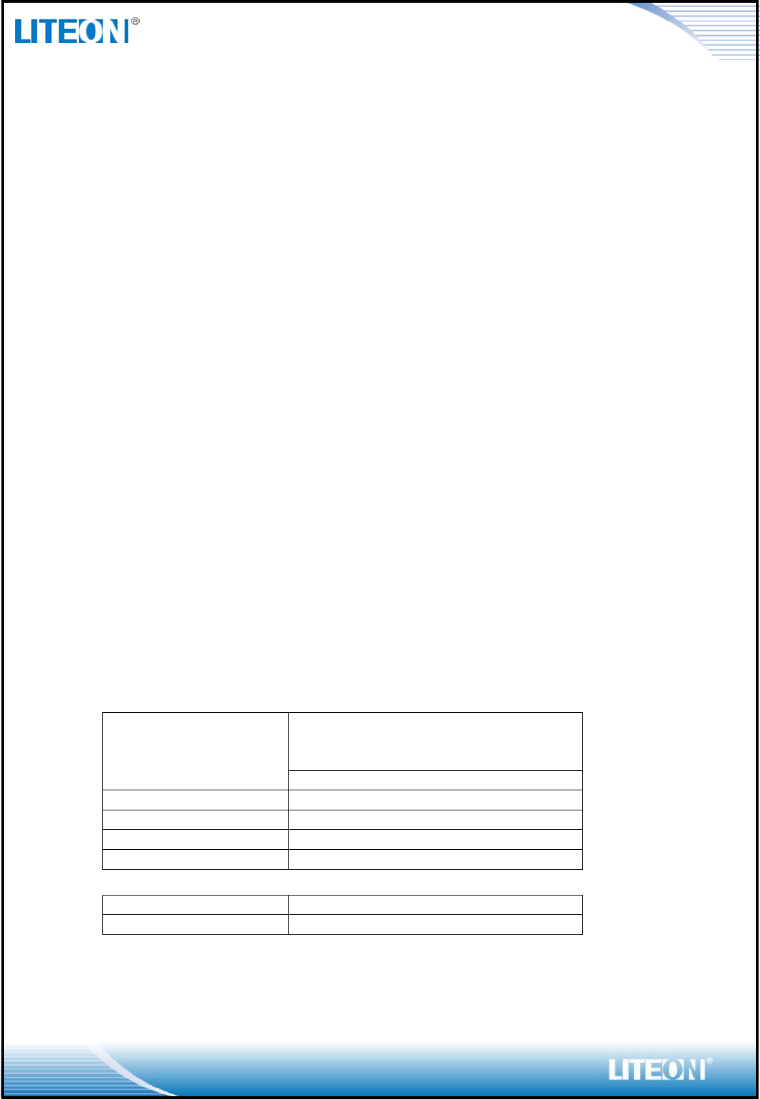
5. Electrical Characteristics
Main chipset
Qualcomm Atheros QCA9565
Functional Specifications
BT Function
Standard
Bluetooth V4.0LE, V3.0 HS, V2.1+EDR,
Bus Interface
USB
Data Rate
1 Mbps, 2Mbps and Up to 3Mbps
Modulation Scheme
GFSK, π/4-DQPSK and 8-DPSK
Frequency Range
2.402~2.480 GHz
Transmit Output Power
-6 ≤ Output Power ≤ +4; Class 2 Device
Receiver Sensitivity
< 0.1% BER at -70dBm
Software
Bluetooth Suite
WiFi Function
Standard
IEEE802.11b; IEEE 802.11g; IEEE 802.11n
Bus Interface
PCI Express
Data Rate
802.11b:
11, 5.5, 2, 1 Mbps
802.11g:
54, 48, 36, 24, 18, 12, 9, 6 Mbps
802.11n:
MCS 0 to 7 for HT20MHz
MCS 0 to 7 for HT40MHz
Media Access Control
CSMA/CA with ACK
Modulation Techniques:
802.11b:
CCK, DQPSK, DBPSK
802.11g, 11a:
64QAM, 16QAM, QPSK, BPSK
802.11n:
BPSK, QPSK, 16QAM, 64QAM
Network Architecture
Ad-hoc mode (Peer-to-Peer )
Infrastructure mode
Operation Channel
2.4GHz
11: (Ch. 1-11) – United States
13: (Ch. 1-13) – Europe
14: (Ch. 1-14) – Japan
Frequency Range
802.11bg
2.412 ~ 2.4835 GHz
Transmit Output Power – 2x2
(Tolerance: +-2dBm)
802.11b / CCK :
17 dBm@6,9,12,18,24Mbps
802.11g / OFDM:
18 dBm@6,9,12,18,24Mbps
17 dBm@36Mbps
Page 6/18
16 dBm@48Mbps
14 dBm@54Mbps
802.11n / HT20:
17 dBm@MCS0,1,2,3,4
16 dBm@MCS5
15 dBm@MCS6
13 dBm@MCS7
802.11n / HT40:
16 dBm@MCS0,1,2,3,4
16 dBm@MCS5
15 dBm@MCS6
13 dBm@MCS7
Receive Sensitivity
802.11b:
Less than -76dBm
802.11g / 11a:
Less than -82dBm @ 6Mpbs
Less than -65dBm @54Mbps
802.11n:
HT20
Less than -82dBm @ MCS0
Less than -64dBm @ MCS7
HT40
Less than -79dBm @ MCS0
Less than -61dBm @ MCS7
Security
WPA, WPA2, WPS, IEEE 802.1X, IEEE 802.11i
Common Function
Operating Voltage
3.3 V ± 10% I/O supply voltage
Antenna Type
Dual MHF4 RF connector
Operating/Storage Temperature
Operating
Operating Temperature: 0 to 75 C
Relative Humidity: 5-90% (non-condensing)
Storage
Temperature: -40 to 85 C
Relevant Humidity: 5-95% (non-condensing)
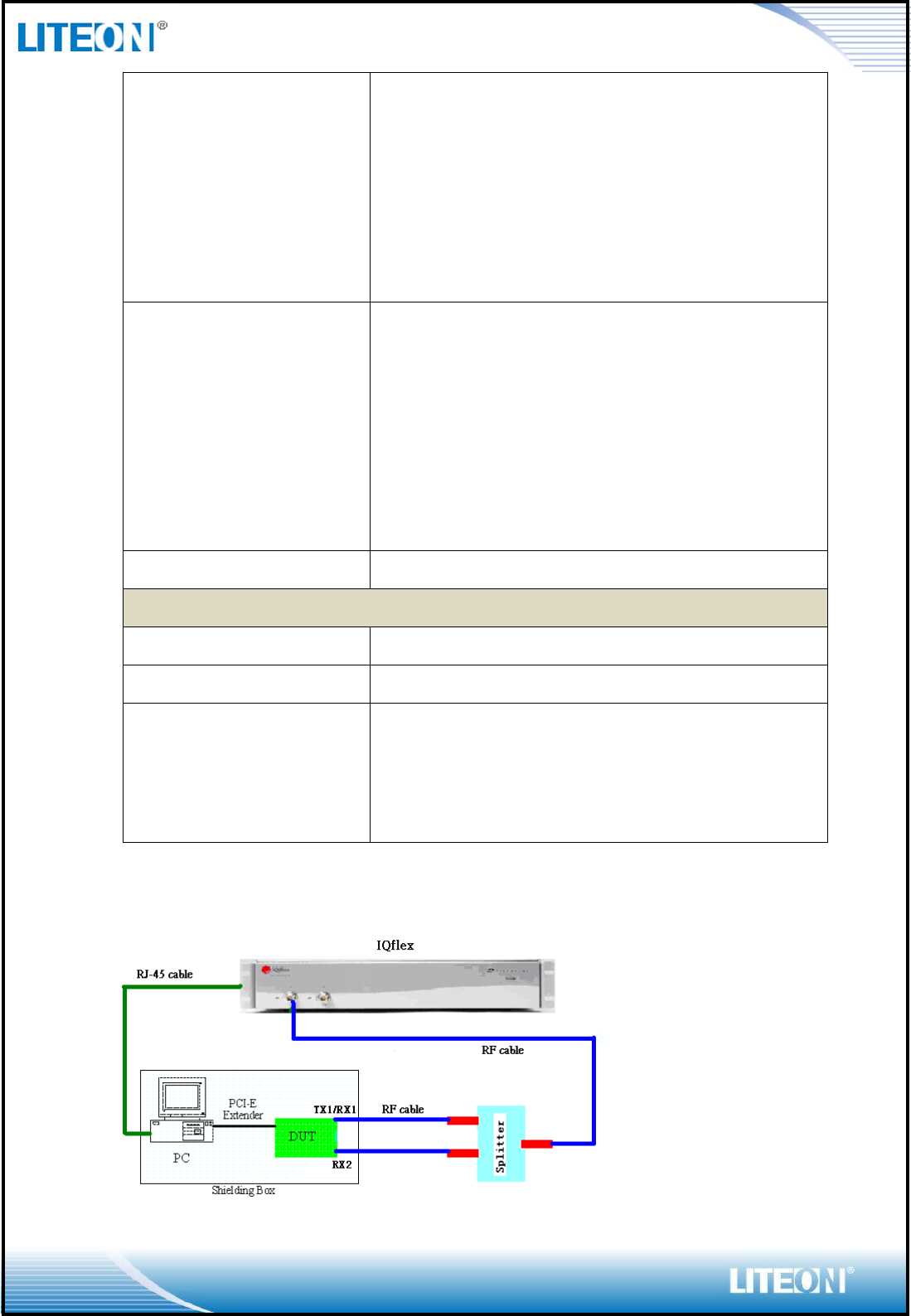
6. Test Setup
Page 7/18
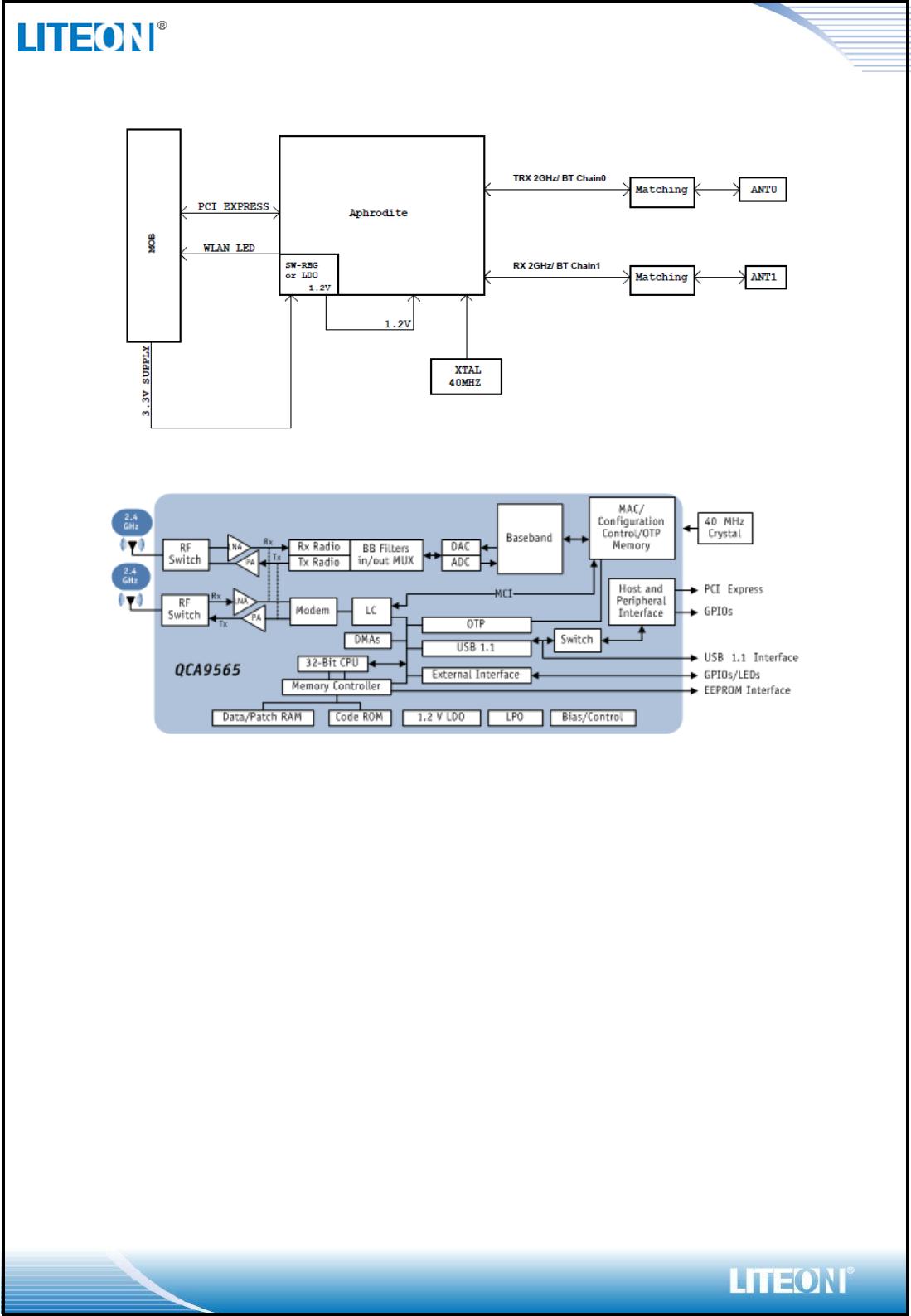
7. Internal Block Diagram
8. Basic Theory
Page 8/18
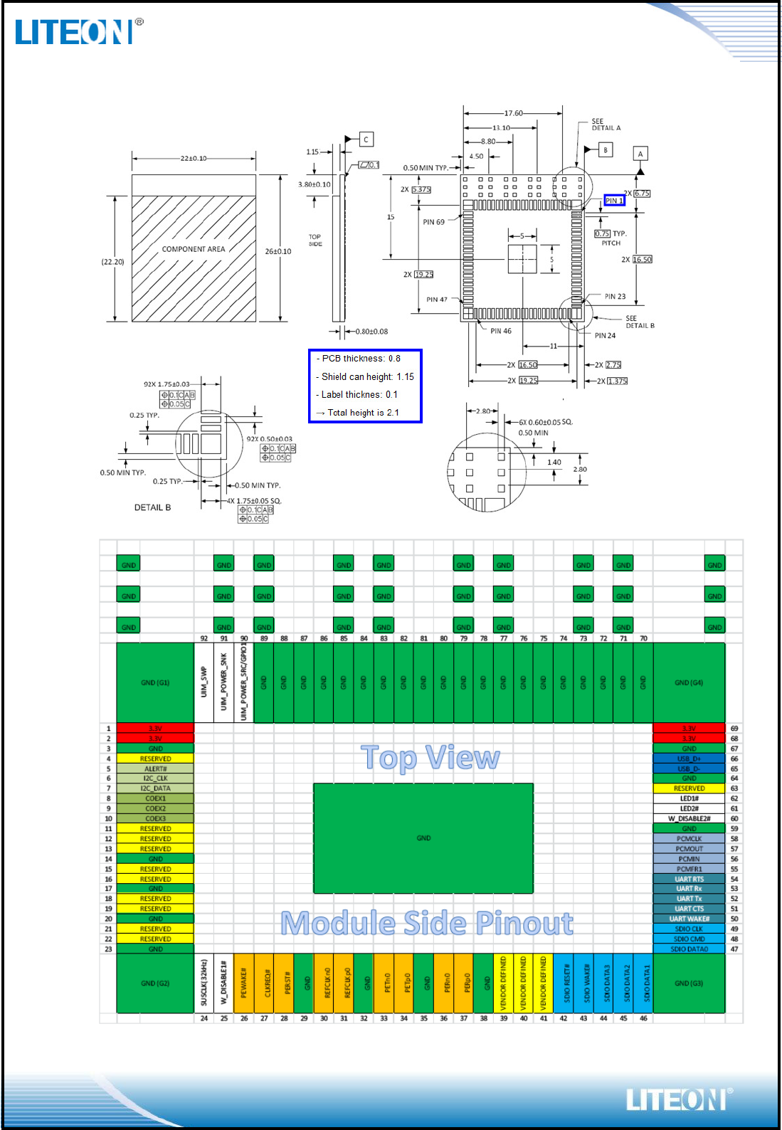
9. Pin Definiton
Page 9/18
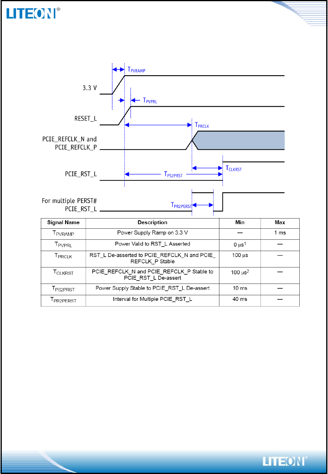
10. Application Note
Power up sequencing:
Page 10/18
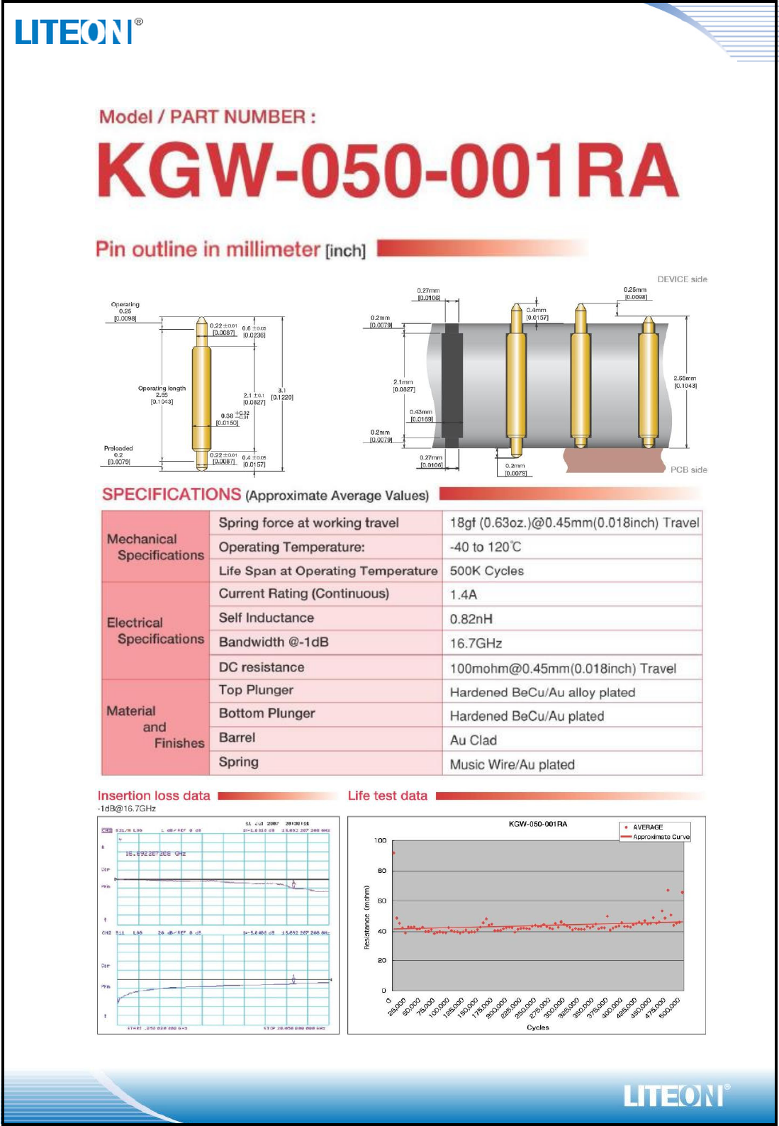
11. Specification of Measurement JIG
Page 11/18
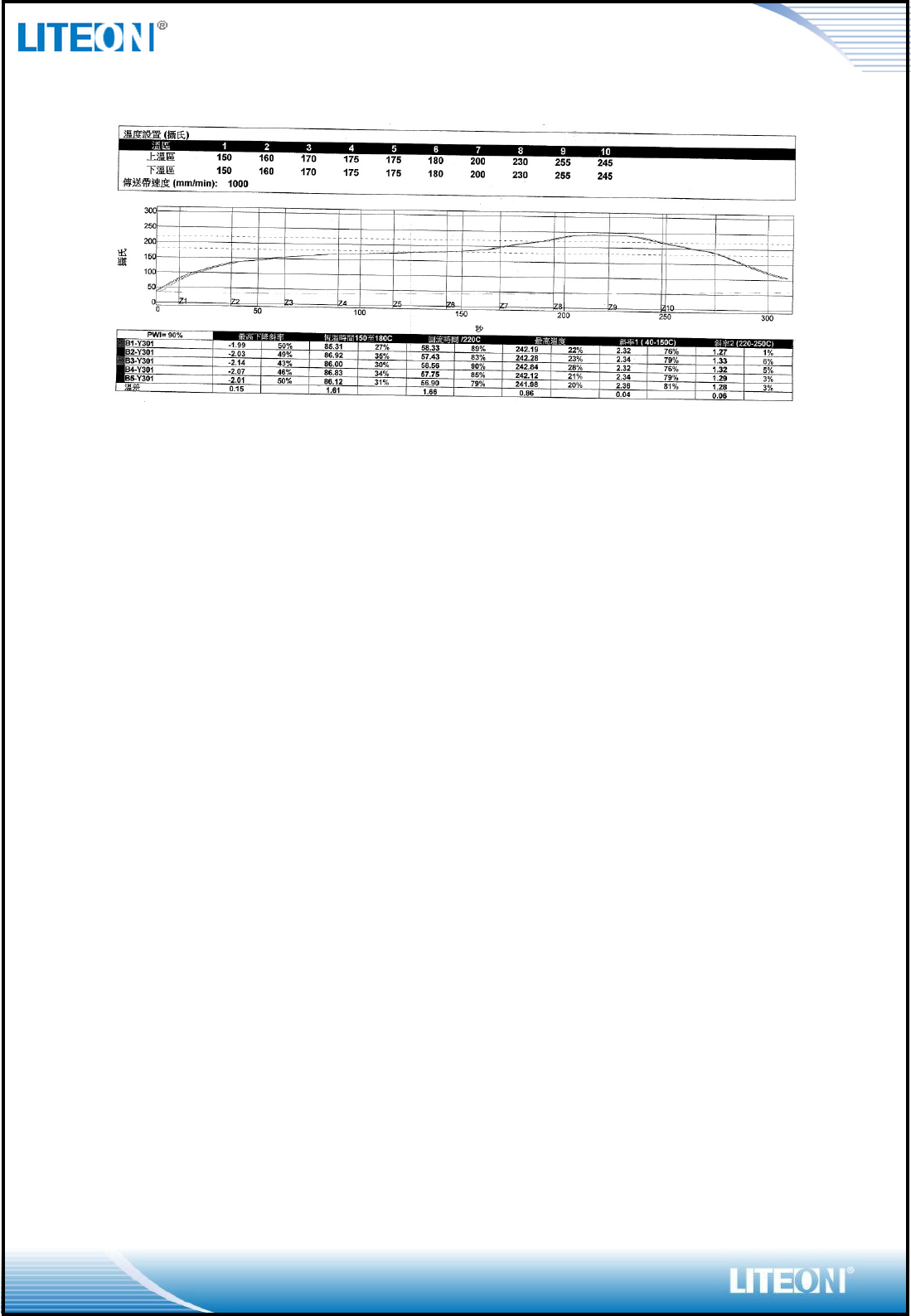
12. Reflow Profile
13. Initial Test Report
Page 12/18
14. Reliability Test Report
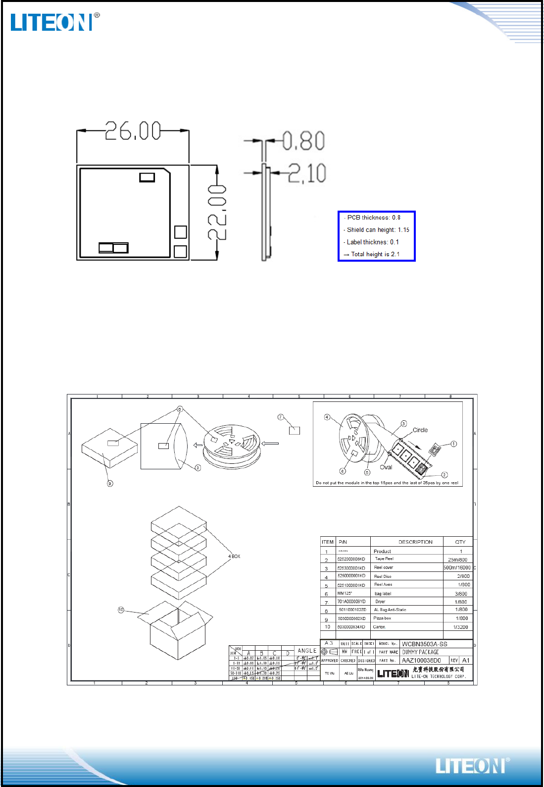
15. Mechanical Characteristics
Tolerance: +/- 0.1mm
16. Structure and Material
17. Packaging Reel & Tape
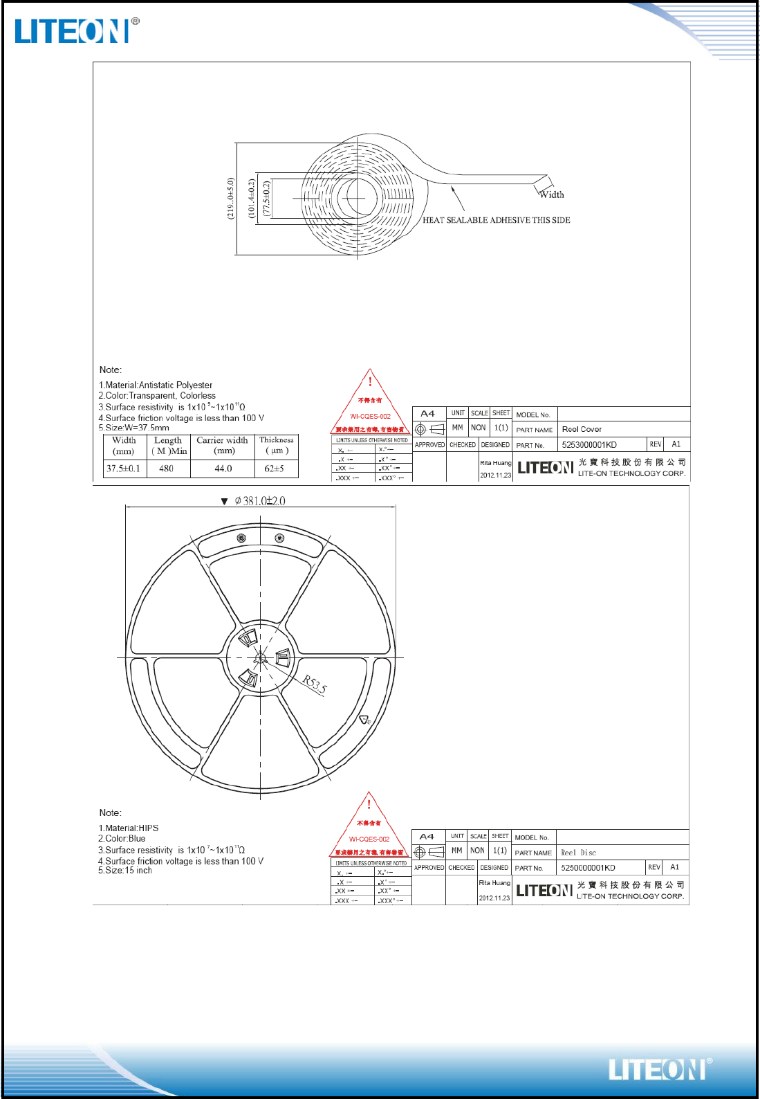
Page 13/18
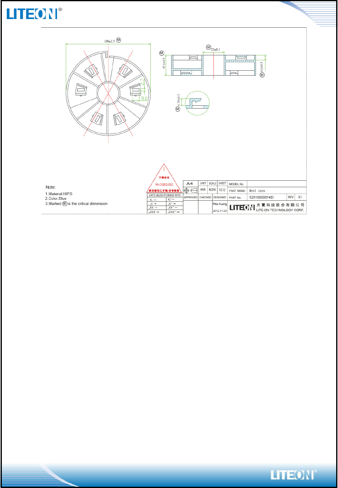
Page 14/18
Page 15/18
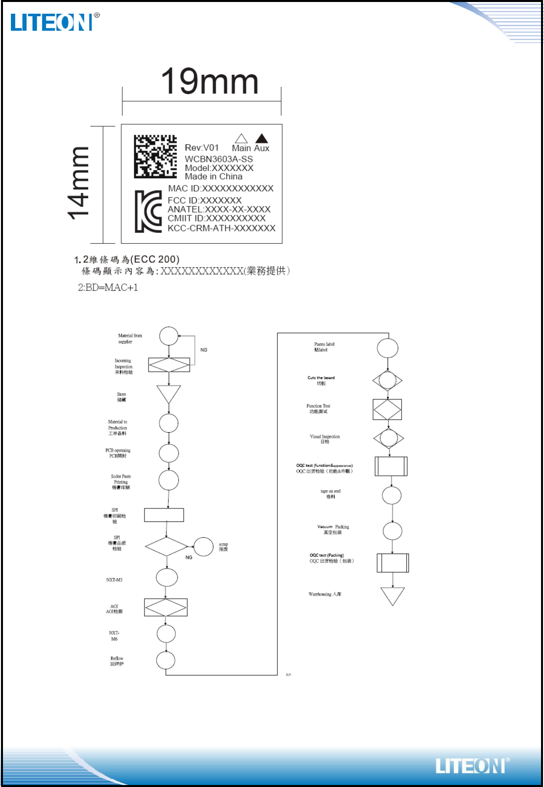
18. Marking
19. Control Chart
Page 16/18
20. Lead Free
This product is a module not IC which has no outside terminal, the contact with
customer platform is through the bottom pad. We don’t do whisker test for module.
21. RoHS Qualification Report
22. Sample History
23. BOM List
Page 17/18
Federal Communication Commission Interference Statement
This equipment has been tested and found to comply with the limits for a Class B
digital device, pursuant to Part 15 of the FCC Rules. These limits are designed to
provide reasonable protection against harmful interference in a residential
installation. This equipment generates, uses and can radiate radio frequency
energy and, if not installed and used in accordance with the instructions, may
cause harmful interference to radio communications. However, there is no
guarantee that interference will not occur in a particular installation. If this
equipment does cause harmful interference to radio or television reception, which
can be determined by turning the equipment off and on, the user is encouraged to
try to correct the interference by one of the following measures:
-Reorient or relocate the receiving antenna.
-Increase the separation between the equipment and receiver.
-Connect the equipment into an outlet on a circuit different from that
to which the receiver is connected.
-Consult the dealer or an experienced radio/TV technician for help.
FCC Caution: Any changes or modifications not expressly approved by the party
responsible for compliance could void the user's authority to operate this
equipment.
This device complies with Part 15 of the FCC Rules. Operation is subject to the
following two conditions: (1) This device may not cause harmful interference, and
(2) this device must accept any interference received, including interference that
maycause undesired operation.
IMPORTANT NOTE:
Radiation Exposure Statement:
This equipment complies with FCC radiation exposure limits set forth for an
uncontrolled environment. This equipment should be installed and operated with
minimum distance 20cm between the radiator & your body.
This transmitter must not be co-located or operating in conjunction with any other
antenna or transmitter.
Country Code selection feature to be disabled for products marketed to
theUS/CANADA
Antenna General Information
Model
Used for
Ant. Type
Connector
Gain (dBi)
Main
Wi-Fi
PIFA
U.FL
3 @ 2.4GHz
Aux
Bluetooth
PIFA
U.FL
3.62 @ 2.4GHz
Note: An extended coax cable was supplied for this antenna with below info.:
Cable loss: 1dB
Connector type: U.FL
Page 18/18
This device is intended only for OEM integrators under the following
conditions:
1) The antenna must be installed such that 20 cm is maintained between the
antenna and users, and
2) The transmitter module may not be co-located with any other transmitter or
antenna,
3) For all products market in US, OEM has to limit the operation channels in CH1
to CH11 for 2.4G band by supplied firmware programming tool. OEM shall not
supply any tool or info to the end-user regarding to Regulatory Domain change.
As long as 3 conditions above are met, further transmittertest will not be required.
However, the OEM integrator is still responsible for testing their end-product for
any additional compliance requirements required with this module installed
IMPORTANT NOTE
In the event that these conditions can not be met(for example certain laptop
configurations or co-location with another transmitter), then the FCC authorization
is no longer considered valid and the FCC ID can notbe used on the final product.
In these circumstances, the OEM integrator will be responsible for re-evaluating
the end product (including the transmitter) and obtaining a separate FCC
authorization.
End Product Labeling
This transmitter module is authorized only for use in device where the antenna
may be installed such that 20 cm may be maintained between the antenna and
users. The final end product must be labeled in a visible area with the following:
“Contains FCC ID:PPQ-SS335”.
Manual Informationto the End User
The OEM integrator has to be aware not to provide information to the end user
regarding how to install or remove this RF module in the user’smanual of the end
product which integratesthis module.
The end user manual shall include all required regulatory information/warning as show in
this manual.