LITE ON TECHNOLOGY WM862FEMD 802.11ac 2x2 MIMO PCI Express Mini Card User Manual Product Specifications
LITE-ON Technology Corp. 802.11ac 2x2 MIMO PCI Express Mini Card Product Specifications
UserManual.wiki
>
LITE ON TECHNOLOGY
>
WM862FEMD User Manual
User Manual
Navigation menu
Upload a User Manual
Namespaces
Wiki Guide
HTML
PDF
Info
Views
User Manual
Discussion / Help
Navigation
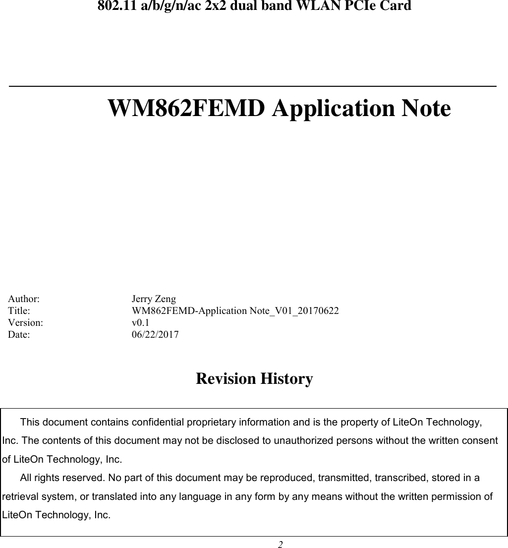
![10 2. Application Note 2.1 Login IP address: 192.168.1.1 Telnet login: username & password are not needed. 2.2 WiFi setting commands Only need to run below commands once. uci set wireless.@wifi-device[2].country=US uci set wireless.@wifi-device[2].hwmode=11ac uci set wireless.@wifi-device[2].disabled=0 uci set wireless.@wifi-device[2].htmode=VHT80 uci set wireless.@wifi-device[2].channel=149 uci set wireless.@wifi-device[2].txchainmask=3 uci set wireless.@wifi-device[2].rxchainmask=3 uci set wireless.@wifi-iface[2].wds=1 uci set wireless.@wifi-iface[2].mode=ap uci set wireless.@wifi-iface[2].ssid=WP8333-wifi2 uci set wireless.@wifi-iface[2].encryption=none uci set wireless.@wifi-iface[2].device=wifi2 uci commit wireless wifi iwconfig a) Set country code uci set wireless.@wifi-device[2].country=US uci commit wireless wifi uci set wireless.@wifi-device[2].country=GB uci commit wireless wifi](https://usermanual.wiki/LITE-ON-TECHNOLOGY/WM862FEMD/User-Guide-3441550-Page-9.png)
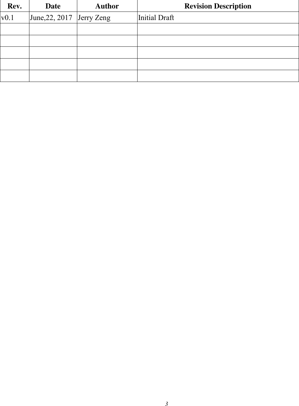
![11 Regulatory domain Country code FCC US CE GB IC CA Japan JP (for 2.4G radio) 4015 (for 5G radio) b) Set wireless mode - Radio 3: uci set wireless.@wifi-device[2].hwmode=11ac uci commit wireless wifi Note: available hwmode for Radio 3: 11b, 11g, 11ng, 11a, 11na, 11ac c) Set bandwidth and channel - Radio 3: uci set wireless.@wifi-device[2].htmode=VHT80 uci set wireless.@wifi-device[2].channel=149 uci commit wireless wifi Note: available htmode for Radio 3: VHT80, HT40+, HT40-, HT20 VHT80 is only applicable for 11ac mode. 2.3 Continuous Rx command 2.4G: uci set wireless.wifi2.disabled=0 && uci set wireless.wifi2.hwmode='11ng' && uci set wireless.wifi2.htmode='HT40+' && uci set wireless.wifi2.channel='1' && uci set wireless.@wifi-iface[2].mode='monitor' &&](https://usermanual.wiki/LITE-ON-TECHNOLOGY/WM862FEMD/User-Guide-3441550-Page-10.png)
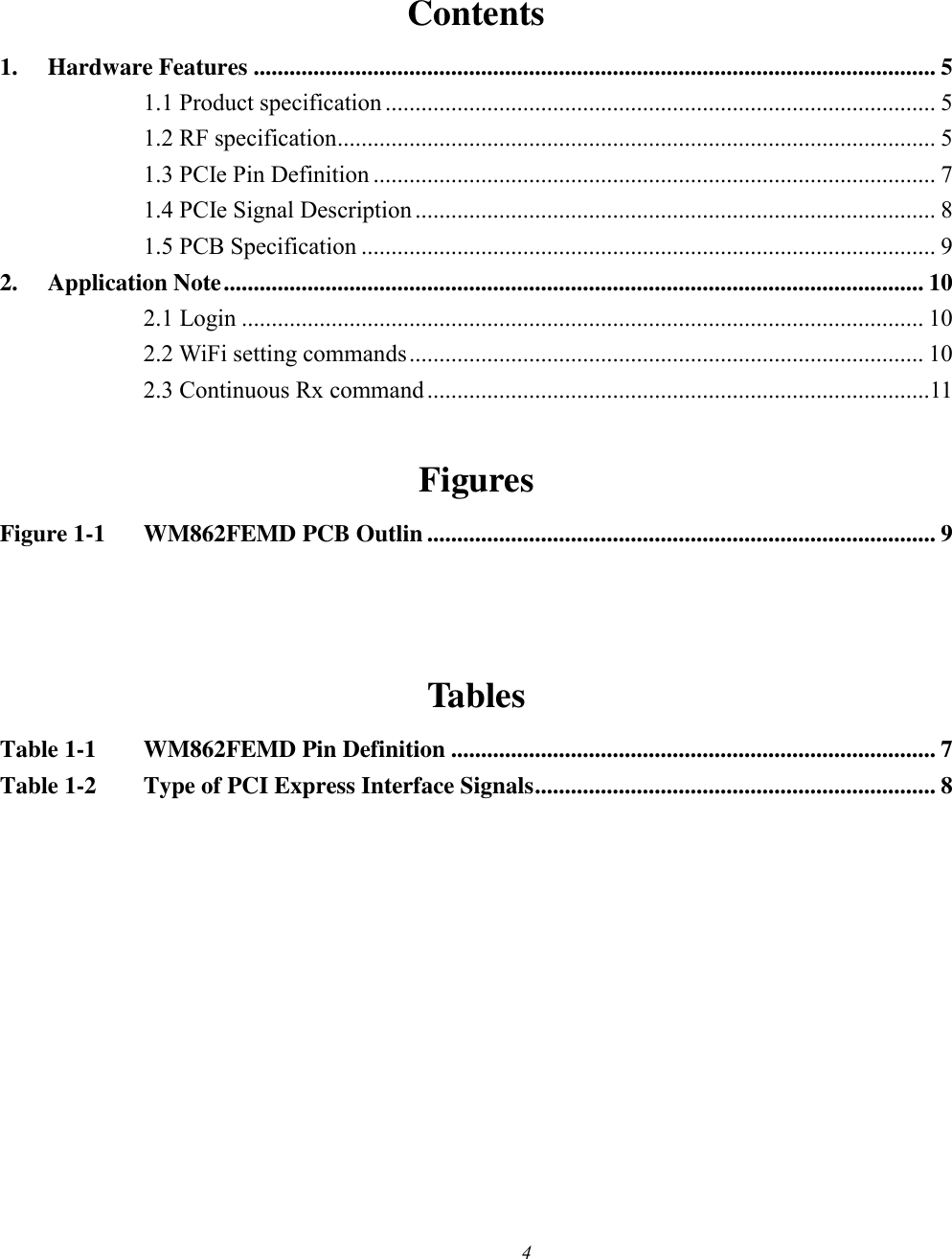
![12 uci commit wireless && wifi Note: available hwmode for Radio 3 2G: 11b, 11g, 11ng, available htmode for Radio 3 2G: HT40+, HT40-, HT20 5G: uci set wireless.wifi2.disabled=0 && uci set wireless.wifi2.hwmode='11ac' && uci set wireless.wifi2.htmode='VHT80' && uci set wireless.wifi2.channel='149' && uci set wireless.@wifi-iface[2].mode='monitor' && uci commit wireless && wifi Note: available hwmode for Radio 3 5G: 11a, 11na, 11ac available htmode for Radio 3 5G: VHT80, HT40+, HT40-, HT20](https://usermanual.wiki/LITE-ON-TECHNOLOGY/WM862FEMD/User-Guide-3441550-Page-11.png)