LITE ON TECHNOLOGY WN4515L 802.11a/b/g/n/ac,2T2R Wireless LAN USB2.0 Module User Manual LiteOn Technology Corp
LITE-ON Technology Corp. 802.11a/b/g/n/ac,2T2R Wireless LAN USB2.0 Module LiteOn Technology Corp
User Manual

Page 1/13
PRODUCT SPECIFICATION
802.11a/b/g/n/ac, 2T2R Wireless LAN USB2.0 Module
WN4515L
Realtek RTL8812AU
Version 1.0
User Manual
* This document contains confidential proprietary information and is property of LTC. The contents of
this document should not be disclosed to unauthorized persons without the written consent of LTC
Page 2/13
CONTENT
FCC WARING STATEMENT .......................................................................................................... 3
IC WARING STATEMENT .............................................................................................................. 4
PRODUCT FEATURES .................................................................................................................... 6
PRODUCT SPECIFICATIONS ........................................................................................................ 7
MAIN CHIPSET ....................................................................................................................................... 7
FUNCTIONAL SPECIFICATIONS ............................................................................................................... 7
RECOMMENDED OPERATION CONDITIONS .......................................................................... 9
DC CHARACTERISTICS ................................................................................................................. 9
PIN ASSIGNMENT .......................................................................................................................... 10
CONNECTOR SPEC ....................................................................................................................... 10
MECHANICAL ................................................................................................................................ 11
METAL ANTENNA SPEC .................................................................................................................... 12
EEPROM INFORMATION ............................................................................................................ 13
ENVIRONMENTAL ........................................................................................................................ 13
OPERATING .......................................................................................................................................... 13
STORAGE .............................................................................................................................................. 13

Page 3/13
FCC WARING STATEMENT
FEDERAL COMMUNICATIONS COMMISSION INTERFERENCE
STATEMENT
This equipment has been tested and found to comply with the limits for a Class B
digital device, pursuant to Part 15 of the FCC Rules. These limits are designed to
provide reasonable protection against harmful interference in a residential installation.
This equipment generates, uses and can radiate radio frequency energy and, if not
installed and used in accordance with the instructions, may cause harmful interference
to radio communications. However, there is no guarantee that interference will not
occur in a particular installation. If this equipment does cause harmful interference to
radio or television reception, which can be determined by turning the equipment off and
on, the user is encouraged to try to correct the interference by one or more of the
following measures:
– Reorient or relocate the receiving antenna.
– Increase the separation between the equipment and receiver.
– Connect the equipment into an outlet on a circuit different from that to which the
receiver is connected.
– Consult the dealer or an experienced radio/TV technician for help.
CAUTION:
Any changes or modifications not expressly approved by the party responsible for
compliance could void the user's authority to operate the equipment.
This device complies with Part 15 of the FCC Rules. Operation is subject to the
following two conditions:
(1) This device may not cause harmful interference and
(2) This device must accept any interference received, including interference that may
cause undesired operation.
RF exposure warning
This equipment complies with FCC RF radiation exposure limits set forth for an
uncontrolled environment. This equipment must be installed and operated in accordance
with provided instructions and must not be co-located or operating in conjunction with
any other antenna or transmitter. End-users and installers must be provided with
antenna installation instructions and transmitter operating conditions for satisfying RF
exposure compliance.

Page 4/13
End Product Labeling
This transmitter module is authorized only for use in device where the antenna may be
installed such that 20cm may be maintained between the antenna and users. The final
end product must be labeled in a visible area with the following: "Contains FCC ID:
PPQ-WN4515L ”
Information for the OEMs and Integrators
The following statement must be included with all versions of this document supplied
to an
OEM or integrator, but should not be distributed to the end user.
1) This device is intended for OEM integrators only.
2) Please see the full Grant of Equipment document for other restrictions.
This device is operation in 5.15 – 5.25GHz frequency range, then restricted in indoor
use only, Outdoor operations in the 5150~5250MHz is prohibit.
This device is slave equipment, the device is not radar detection and not ad-hoc
operation in the DFS band.
IC WARING STATEMENT
Canada, avis d'Industry Canada (IC)
This device complies with Industry Canada’s licence-exempt RSSs. Operation is
subject to the following two conditions:
(1)This device may not cause interference; and
(2)This device must accept any interference, including interference that may cause
undesired operation of the device.
Le présent appareil est conforme aux CNR d'Industrie Canada applicables aux
appareils radio exempts de licence. L'exploitation est autorisée aux deux conditions
suivantes : (1) l'appareil ne doit pas produire de brouillage, et (2) l'utilisateur de
l'appareil doit accepter tout brouillage radioélectrique subi, même si le brouillage est
susceptible d'en compromettre le fonctionnement.
This device is restricted to indoor use.
Page 5/13
OEM integrator is still responsible for testing their end product for any additional
compliance requirements required with this module installed (for example, digital device
emissions, PC peripheral requirements, etc.).
IMPORTANT NOTE: In the event that these conditions cannot be met (for example
certain laptop configurations or co-location with another transmitter), then the IC
authorization is no longer considered valid and the IC No. cannot be used on the final
product. In these circumstances, the OEM integrator will be responsible for re-evaluating
the end product (including the transmitter) and obtaining a separate IC authorization.
End Product Labeling
This transmitter module is authorized only for use in device where the antenna may be
installed such that 20 cm may be maintained between the antenna and users. The final
end product must be labeled in a visible area with the following: “Contains transmitter
module IC: 4491A-WN4515L”.
Contient le module d'émission IC: 4491A-WN4515L
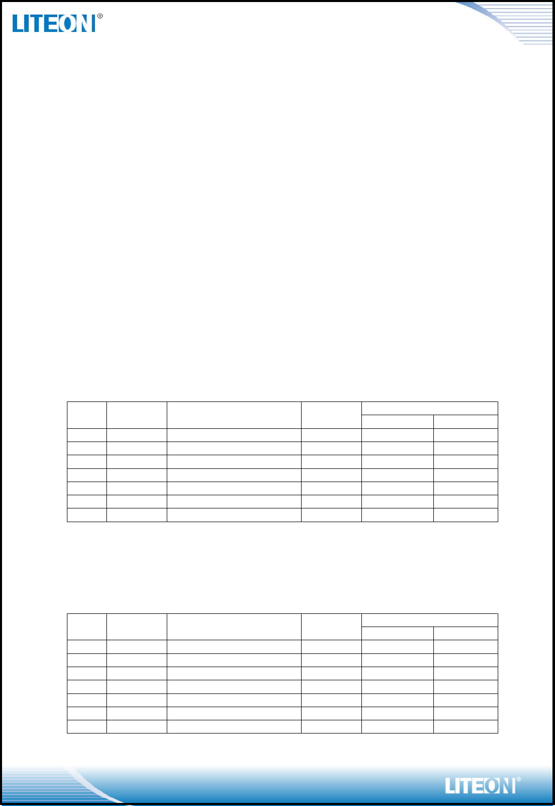
This radio transmitter (4491A-WN4515L) has been approved by Industry Canada to
operate with the antenna types listed below with the maximum permissible gain indicated.
Antenna types not included in this list, having a gain greater than the maximum gain
indicated for that type, are strictly prohibited for use with this device.
Ant. Brand Model Type
Gain(dBi)
2.4G
5G
1
PSA
RFMTA401029IMLB701
PIFA
2.60
3.16
2
PSA
RFMTA401029IMLB701
PIFA
1.89
2.90
3
PSA
RFMTA401029IMLB701
PIFA
1.75
1.99
4
PSA
RFMTA401029IMLB701
PIFA
1.71
1.97
5
PSA
RFMTA401029IMLB701
PIFA
1.72
1.85
6
PSA
RFMTA401029IMLB701
PIFA
1.62
1.72
7
PSA
RFMTA100600NNLB002
PIFA
0.52
2.66
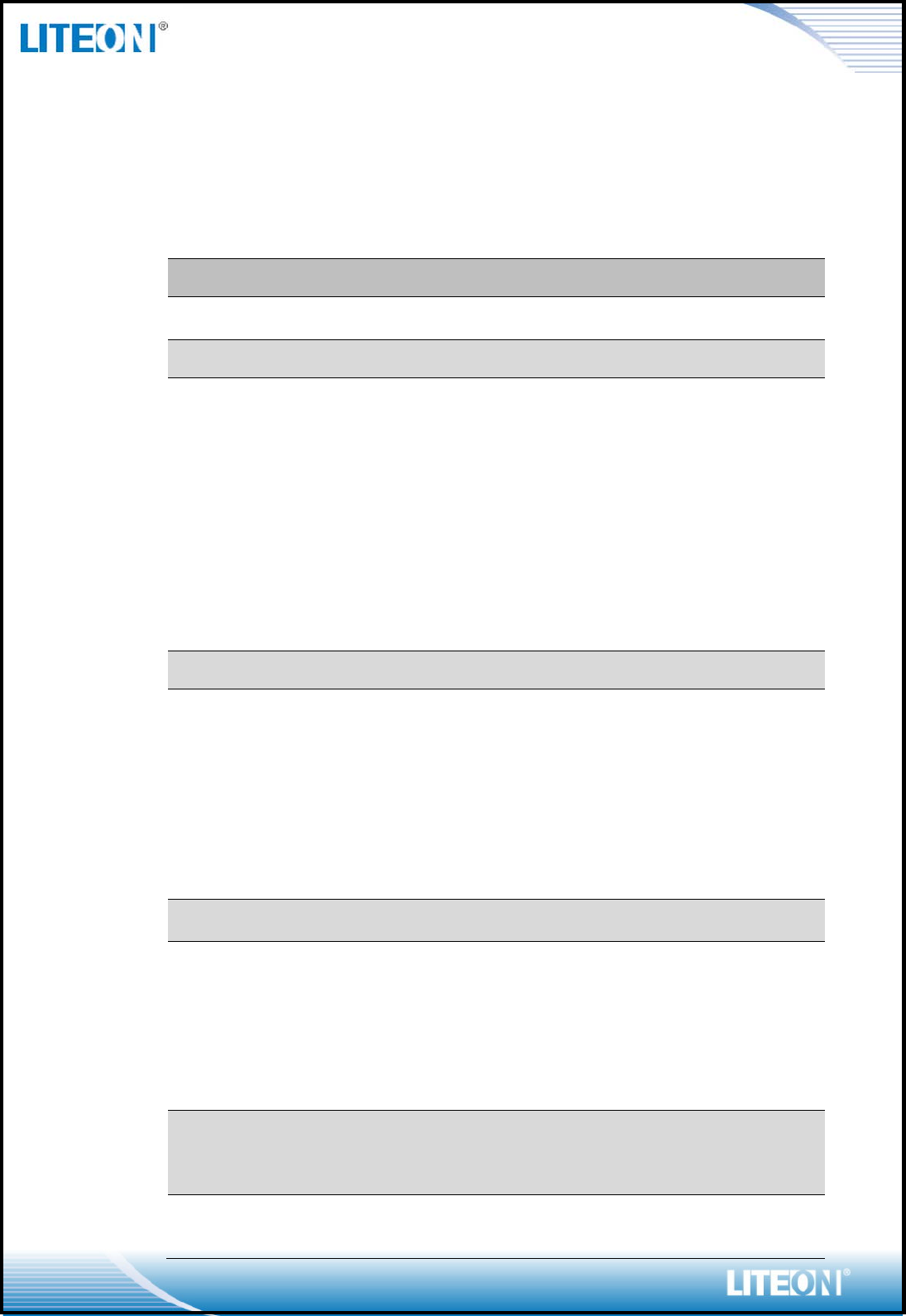
Le présent émetteur radio (4491A-WN4515L) a été approuvé par Industrie Canada pour
fonctionner avec les types d'antenne énumérés ci-dessous et ayant un gain admissible
maximal et l'impédance requise pour chaque type d'antenne. Les types d'antenne non
inclus dans cette liste, ou dont le gain est supérieur au gain maximal indiqué, sont
strictement interdits pour l'exploitation de l'émetteur.
Ant. Brand Model Type
Gain(dBi)
2.4G
5G
1
PSA
RFMTA401029IMLB701
PIFA
2.60
3.16
2
PSA
RFMTA401029IMLB701
PIFA
1.89
2.90
3
PSA
RFMTA401029IMLB701
PIFA
1.75
1.99
4
PSA
RFMTA401029IMLB701
PIFA
1.71
1.97
5
PSA
RFMTA401029IMLB701
PIFA
1.72
1.85
6
PSA
RFMTA401029IMLB701
PIFA
1.62
1.72
7
PSA
RFMTA100600NNLB002
PIFA
0.52
2.66

Page 6/13
The transmitter module may not be co-located with any other transmitter or antenna.
Le module émetteur peut ne pas être coïmplanté avec un autre émetteur ou antenne.
Radio Frequency (RF) Exposure Information
The radiated output power of the Wireless Device is below the Industry Canada (IC)
radio frequency exposure limits. The Wireless Device should be used in such a manner
such that the potential for human contact during normal operation is minimized.
This device has also been evaluated and shown compliant with the IC RF Exposure
limits under mobile exposure conditions. (antennas are greater than 20cm from a
person's body).
Informations concernant l'exposition aux fréquences radio (RF)
La puissance de sortie émise par l’appareil de sans fil est inférieure à la limite
d'exposition aux fréquences radio d'Industry Canada (IC). Utilisez l’appareil de sans fil
de façon à minimiser les contacts humains lors du fonctionnement normal.
Ce périphérique a également été évalué et démontré conforme aux limites d'exposition
aux RF d'IC dans des conditions d'exposition à des appareils mobiles (les antennes se
situent à moins de 20 cm du corps d'une personne).
PRODUCT FEATURES
Operate at ISM frequency Band (2.4/5GHz)
IEEE Standards Support, 802.11a, 802.11b, 802.11g, 802.11n,and 802.11ac
USB 2.0 support for date rates up to 12Mbps full speed and 480Mbps high speed
Enterprise level security supporting: WEP 64/128, WPA, WPA2, WAPI
Support 2 transmission and 2 receiving, transmission rate can up to 300Mbps
(Physical Rate) in 802.11n; and 866.7Mbps in 802.11ac
Wi-Fi Direct supports wireless peer to peer applications
RoHS compliance
Low Halogen compliance
Page 7/13
PRODUCT SPECIFICATIONS
MAIN CHIPSET
MAC/ Baseband/ RF: Realtek 8812AU-VS-CG
FUNCTIONAL SPECIFICATIONS
WiFi Function
Standard
IEEE802.11a; IEEE802.11b; IEEE 802.11g; IEEE
802.11n; IEEE802.11ac
Bus Interface Universal Serial Bus (USB2.0)
Data Rate
802.11a:
54, 48, 36, 24, 18, 12, 9, 6 Mbps
802.11b:
11, 5.5, 2, 1 Mbps
802.11g:
54, 48, 36, 24, 18, 12, 9, 6 Mbps
802.11n:
MCS 0 to 15 for HT20MHz
MCS 0 to 15 for HT40MHz
802.11ac:
MCS 0 to 8 for HT20MHz
MCS 0 to 9 for HT40MHz
MCS 0 to 9 for HT80MHz
Media Access Control CSMA/CA with ACK
Modulation Techniques
802.11a:
54, 48, 36, 24, 18, 12, 9, 6 Mbps
802.11b:
CCK, DQPSK, DBPSK
802.11g:
64QAM, 16QAM, QPSK, BPSK
802.11n:
64QAM, 16QAM, QPSK, BPSK
802.11ac:
256QAM, 64QAM, 16QAM, QPSK, BPSK
Network Architecture
Ad-hoc mode (Peer-to-Peer)
Infrastructure mode
Operation Channel
5GHz
12: – United States
19: – Europe
8: – Japan
2.4GHz
11: (Ch. 1-11) – United States
13: (Ch. 1-13) – Europe
14: (Ch. 1-14) – Japan
Frequency Range
802.11a/ac
5.15~5.85 GHz
802.11bg
2.400 ~ 2.4835 GHz
Transmit Output Power –
2x2
(Tolerance: ±1.5dBm)
02.11a:
13 dBm@6-54Mbps
802.11b:
Page 8/13
15 dBm@1-11Mbps
802.11g:
14 dBm@6-54Mbps
802.11n(2.4GHz):
20MHz:
13dBm@MCS0-7
40MHz:
13dBm@MCS0-7
802.11n(5GHz):
20MHz:
12dBm@MCS0-7
40MHz:
12dBm@MCS0-7
802.11ac:
20MHz:
13dBm@MCS0-8
40MHz:
12dBm@MCS0-9
80MHz:
11dBm@MCS0-9
Receiver Sensitivity
802.11a:
-85 dBm@6Mbps
-70 dBm@54Mbps
802.11b:
-83 dBm@11Mbps
802.11g:
-86 dBm@6Mbps
-70 dBm@54Mbps
802.11n(2.4GHz):
20MHz
-69 dBm@MCS7
40MHz
-66 dBm@MCS7
802.11n(5GHz):
20MHz
-69 dBm@MCS7
40MHz
-66 dBm@MCS7
802.11ac:
20MHz
-63 dBm@MCS8
40MHz
-60 dBm@MCS9
80MHz
-57 dBm@MCS9
Security
WPA, WPA2, WPS, WEP 64/128, IEEE 802.1x, IEEE
802.11i
Operating Voltage 5V ±10% I/O supply voltage
OS Supported Microsoft Windows Win7/Win8/Win8.1/Linux
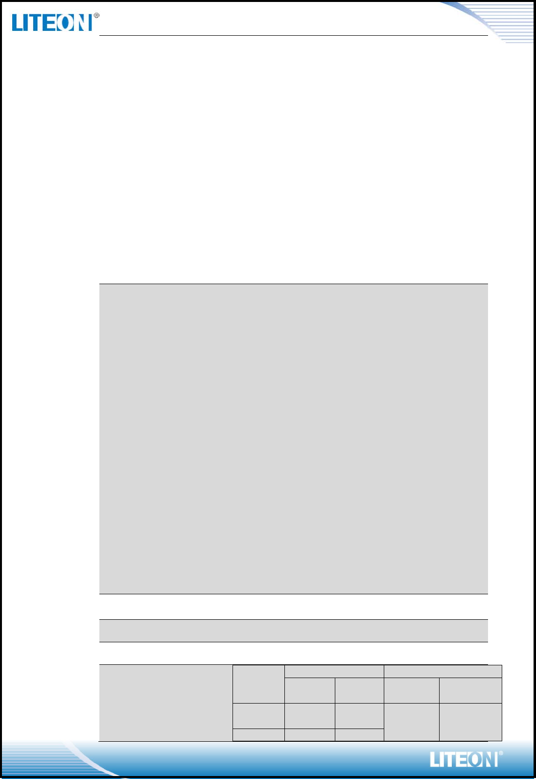
Power Consumption
Test Condition:
- Operate at HT40
- File Transmission
Mode
Average
Peak
2.4G
mA / W
5G
mA / W
2.4G
mA / W
5G
mA / W
TX
420mA /
2.1W
490mA /
2.45W
700mA /
3.5W
930mA /
4.65W
RX
270mA /
332mA /
Page 9/13
1.35W
1.66W
Unassoci
ated Idle
22mA /
0.11W
Standby
@Wake
up mode
20mA /
0.1W
Antenna Type Metal Antenna on Board
RECOMMENDED OPERATION CONDITIONS
For Module
Symbol Rating Min Typ Max Units
VCC 5V Supply Voltage 4.5 5 5.5 V
For IC
Symbol Rating Min Typ Max Units
VDD33 3.3V Supply Voltage 3.0 3.3 3.6 V
VDD12 1.2V Supply Voltage 1.10 1.2 1.23 V
DC CHARACTERISTICS
Symbol Parameter Min Typ Max Units
VIL Input Low Voltage - 0 0.9 V
VIH Input High Voltage 2.0 3.3 3.6 V
VOL Output Low Voltage 0 - 0.33
VOH Output High Voltage 2.97 - 3.3 V
Page 10/13
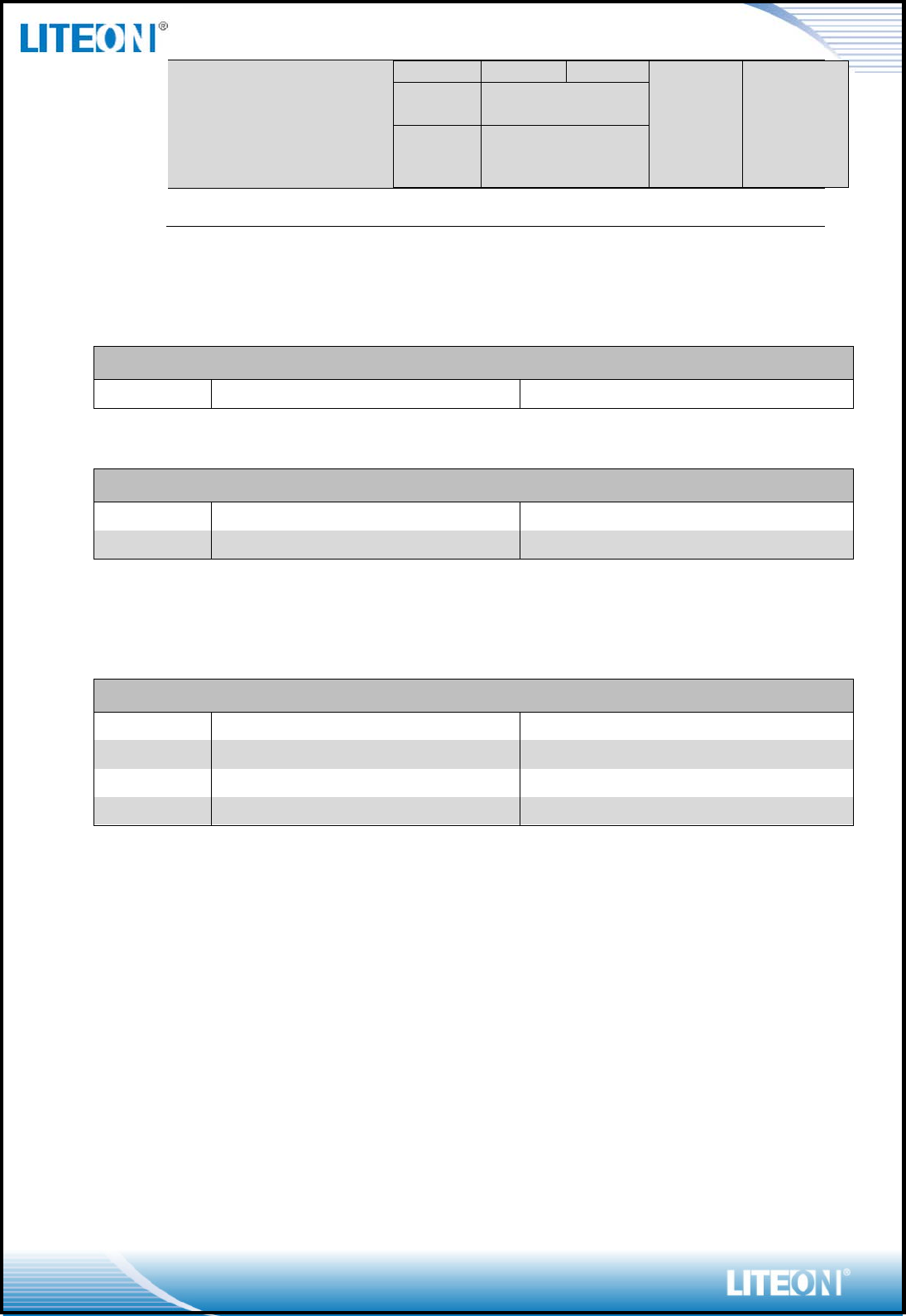
PIN ASSIGNMENT
Pin.
Pin Define
Description
Status
1
+3.3V 3.3V source YES
2
+3.3V
3.3V source
YES
3
USB_D- USB Data- YES
4
USB_D+
USB Data+
YES
5
GND Ground YES
6
WAKE#
Wake up system via wifi, low active
YES
7
RESET# System reset RTL8812AU, low active YES
8
GND
Ground
YES
CONNECTOR SPEC
Page 11/13
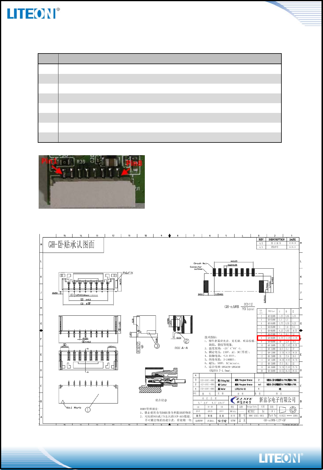
MECHANICAL
Page 12/13
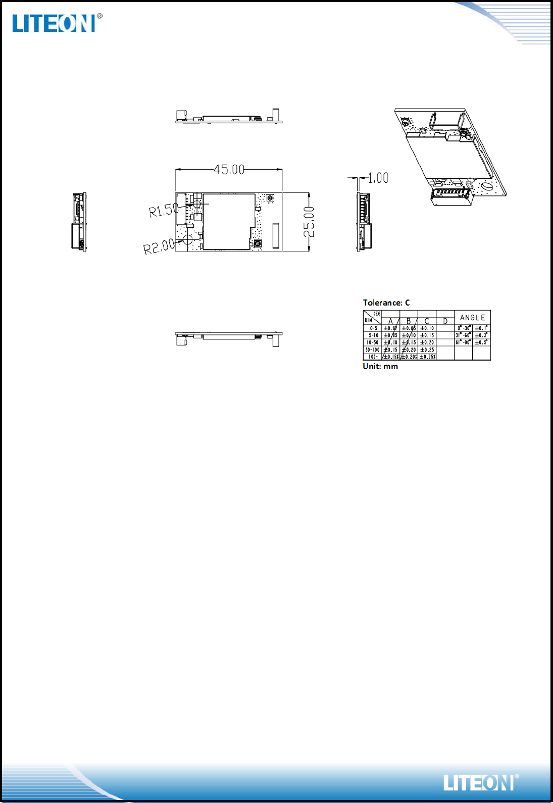
METAL ANTENNA SPEC
On Board Antenna for WiFi (Q’ty:1pcs)
Page 13/13
EEPROM INFORMATION
Reg Domain US
0x25
Vendor ID 0x0BDA
Product ID 0x881A
ENVIRONMENTAL
Operating
Operating Temperature: 0 to 70 °C
Relevant Humidity: 5-90% (non-condensing)
Storage
Temperature: -40 to 85 °C (-40 to 185 °F)
Relevant Humidity: 5-95% (non-condensing)